
Filters
GM1 SPO.OP.205 Airborne collision avoidance system (ACAS)
ED Decision 2019/019/R
GENERAL
(a)The ACAS operational procedures and training programmes established by the operator should take into account this Guidance Material. It incorporates advice contained in:
(1)ICAO Annex 10, Volume IV;
(2)ICAO Doc 8168 (PANS-OPS), Volume III; and
(3)ICAO PANS-ATM.
(b)Additional guidance material on ACAS may be referred to, including information available from such sources as EUROCONTROL.
ACAS FLIGHT CREW TRAINING
(c)During the implementation of ACAS, several operational issues were identified that had been attributed to deficiencies in flight crew training programmes. As a result, the issue of flight crew training has been discussed within the ICAO, which has developed guidelines for operators to use when designing training programmes.
(d)This Guidance Material contains performance-based training objectives for ACAS II flight crew training. Information contained here related to traffic advisories (TAs) is also applicable to ACAS I and ACAS II users. The training objectives cover five areas: theory of operation; pre-flight operations; general in-flight operations; response to TAs; and response to resolution advisories (RAs).
(e)The information provided is valid for version 7 and 7.1 (ACAS II). Where differences arise, these are identified.
(f)The performance-based training objectives are further divided into the areas of: academic training; manoeuvre training; initial evaluation and recurrent qualification. Under each of these four areas, the training material has been separated into those items which are considered essential training items and those which are considered desirable. In each area, objectives and acceptable performance criteria are defined.
(g)ACAS academic training
(1)This training is typically conducted in a classroom environment. The knowledge demonstrations specified in this section may be completed through the successful completion of written tests or through providing correct responses to non-real-time computer-based training (CBT) questions.
(2)Essential items
(i)Theory of operation. The flight crew member should demonstrate an understanding of ACAS II operation and the criteria used for issuing TAs and RAs. This training should address the following topics:
(A)System operation
Objective: to demonstrate knowledge of how ACAS functions.
Criteria: the flight crew member should demonstrate an understanding of the following functions:
(a)Surveillance
(1)ACAS interrogates other transponder-equipped aircraft within a nominal range of 14 NM.
(2)ACAS surveillance range can be reduced in geographic areas with a large number of ground interrogators and/or ACAS II-equipped aircraft.
(3)If the operator's ACAS implementation provides for the use of the Mode S extended squitter, the normal surveillance range may be increased beyond the nominal 14 NM. However, this information is not used for collision avoidance purposes.
(b)Collision avoidance
(1)TAs can be issued against any transponder-equipped aircraft that responds to the ICAO Mode C interrogations, even if the aircraft does not have altitude reporting capability.
(2)RAs can be issued only against aircraft that are reporting altitude and in the vertical plane only.
(3)RAs issued against an ACAS-equipped intruder are co-ordinated to ensure complementary RAs are issued.
(4)Failure to respond to an RA deprives own aircraft of the collision protection provided by own ACAS.
(5)Additionally, in ACAS-ACAS encounters, failure to respond to an RA also restricts the choices available to the other aircraft's ACAS and thus renders the other aircraft's ACAS less effective than if own aircraft were not ACAS equipped.
(B)Advisory thresholds
Objective: to demonstrate knowledge of the criteria for issuing TAs and RAs.
Criteria: the flight crew member should demonstrate an understanding of the methodology used by ACAS to issue TAs and RAs and the general criteria for the issuance of these advisories, including the following:
(a)ACAS advisories are based on time to closest point of approach (CPA) rather than distance. The time should be short and vertical separation should be small, or projected to be small, before an advisory can be issued. The separation standards provided by ATS are different from the miss distances against which ACAS issues alerts.
(b)Thresholds for issuing a TA or an RA vary with altitude. The thresholds are larger at higher altitudes.
(c)A TA occurs from 15 to 48 seconds and an RA from 15 to 35 seconds before the projected CPA.
(d)RAs are chosen to provide the desired vertical miss distance at CPA. As a result, RAs can instruct a climb or descent through the intruder aircraft's altitude.
(C)ACAS limitations
Objective: to verify that the flight crew member is aware of the limitations of ACAS.
Criteria: the flight crew member should demonstrate knowledge and understanding of ACAS limitations, including the following:
(a)ACAS will neither track nor display non-transponder-equipped aircraft, nor aircraft not responding to ACAS Mode C interrogations.
(b)ACAS will automatically fail if the input from the aircraft’s barometric altimeter, radio altimeter or transponder is lost.
(1)In some installations, the loss of information from other on-board systems such as an inertial reference system (IRS) or attitude heading reference system (AHRS) may result in an ACAS failure. Individual operators should ensure that their flight crews are aware of the types of failure which will result in an ACAS failure.
(2)ACAS may react in an improper manner when false altitude information is provided to own ACAS or transmitted by another aircraft. Individual operators should ensure that their flight crew are aware of the types of unsafe conditions which can arise. Flight crew members should ensure that when they are advised, if their own aircraft is transmitting false altitude reports, an alternative altitude reporting source is selected, or altitude reporting is switched off.
(c)Some aeroplanes within 380 ft above ground level (AGL) (nominal value) are deemed to be ‘on ground’ and will not be displayed. If ACAS is able to determine an aircraft below this altitude is airborne, it will be displayed.
(d)ACAS may not display all proximate transponder-equipped aircraft in areas of high density traffic.
(e)The bearing displayed by ACAS is not sufficiently accurate to support the initiation of horizontal manoeuvres based solely on the traffic display.
(f)ACAS will neither track nor display intruders with a vertical speed in excess of 10 000 ft/min. In addition, the design implementation may result in some short-term errors in the tracked vertical speed of an intruder during periods of high vertical acceleration by the intruder.
(g)Ground proximity warning systems/ground collision avoidance systems (GPWSs/GCASs) warnings and wind shear warnings take precedence over ACAS advisories. When either a GPWS/GCAS or wind shear warning is active, ACAS aural annunciations will be inhibited and ACAS will automatically switch to the 'TA only' mode of operation.
(D)ACAS inhibits
Objective: to verify that the flight crew member is aware of the conditions under which certain functions of ACAS are inhibited.
Criteria: the flight crew member should demonstrate knowledge and understanding of the various ACAS inhibits, including the following:
(a)‘Increase Descent’ RAs are inhibited below 1 450 ft AGL.
(b)‘Descend’ RAs are inhibited below 1 100 ft AGL.
(c)All RAs are inhibited below 1 000 ft AGL.
(d)All TA aural annunciations are inhibited below 500 ft AGL.
(e)Altitude and configuration under which ‘Climb’ and ‘Increase Climb’ RAs are inhibited. ACAS can still issue ‘Climb’ and ‘Increase Climb’ RAs when operating at the aeroplane's certified ceiling. (In some aircraft types, ‘Climb’ or ‘Increase Climb’ RAs are never inhibited.)
(ii)Operating procedures
The flight crew member should demonstrate the knowledge required to operate the ACAS avionics and interpret the information presented by ACAS. This training should address the following:
(A)Use of controls
Objective: to verify that the pilot can properly operate all ACAS and display controls.
Criteria: demonstrate the proper use of controls, including the following:
(a)Aircraft configuration required to initiate a self-test.
(b)Steps required to initiate a self-test.
(c)Recognising when the self-test was successful and when it was unsuccessful. When the self-test is unsuccessful, recognising the reason for the failure and, if possible, correcting the problem.
(d)Recommended usage of range selection. Low ranges are used in the terminal area and the higher display ranges are used in the en-route environment and in the transition between the terminal and en-route environment.
(e)Recognising that the configuration of the display does not affect the ACAS surveillance volume.
(f)Selection of lower ranges when an advisory is issued, to increase display resolution.
(g)Proper configuration to display the appropriate ACAS information without eliminating the display of other needed information.
(h)If available, recommended usage of the above/below mode selector. The above mode should be used during climb and the below mode should be used during descent.
(i)If available, proper selection of the display of absolute or relative altitude and the limitations of using this display if a barometric correction is not provided to ACAS.
(B)Display interpretation
Objective: to verify that the flight crew member understands the meaning of all information that can be displayed by ACAS. The wide variety of display implementations require the tailoring of some criteria. When the training programme is developed, these criteria should be expanded to cover details for the operator's specific display implementation.
Criteria: the flight crew member should demonstrate the ability to properly interpret information displayed by ACAS, including the following:
(a)Other traffic, i.e. traffic within the selected display range that is not proximate traffic, or causing a TA or RA to be issued.
(b)Proximate traffic, i.e. traffic that is within 6 NM and ± 1 200 ft.
(c)Non-altitude reporting traffic.
(d)No bearing TAs and RAs.
(e)Off-scale TAs and RAs: the selected range should be changed to ensure that all available information on the intruder is displayed.
(f)TAs: the minimum available display range that allows the traffic to be displayed should be selected, to provide the maximum display resolution.
(g)RAs (traffic display): the minimum available display range of the traffic display that allows the traffic to be displayed should be selected, to provide the maximum display resolution.
(h)RAs (RA display): flight crew members should demonstrate knowledge of the meaning of the red and green areas or the meaning of pitch or flight path angle cues displayed on the RA display. Flight crew members should also demonstrate an understanding of the RA display limitations, i.e. if a vertical speed tape is used and the range of the tape is less than 2 500 ft/min, an increase rate RA cannot be properly displayed.
(i)If appropriate, awareness that navigation displays oriented on ‘Track-Up’ may require a flight crew member to make a mental adjustment for drift angle when assessing the bearing of proximate traffic.
(C)Use of the TA only mode
Objective: to verify that a flight crew member understands the appropriate times to select the TA only mode of operation and the limitations associated with using this mode.
Criteria: the flight crew member should demonstrate the following:
(a)Knowledge of the operator's guidance for the use of TA only.
(b)Reasons for using this mode. If TA only is not selected when an airport is conducting simultaneous operations from parallel runways separated by less than 1 200 ft, and to some intersecting runways, RAs can be expected. If, for any reason, TA only is not selected and an RA is received in these situations, the response should comply with the operator's approved procedures.
(c)All TA aural annunciations are inhibited below 500 ft AGL. As a result, TAs issued below 500 ft AGL may not be noticed unless the TA display is included in the routine instrument scan.
(D)Crew coordination
Objective: to verify that the flight crew member understands how ACAS advisories will be handled.
Criteria: the flight crew member should demonstrate knowledge of the crew procedures that should be used when responding to TAs and RAs, including the following:
(a)task sharing between the pilot flying and the pilot monitoring;
(b)expected call-outs; and
(c)communications with ATC.
(E)Phraseology rules
Objective: to verify that the flight crew member is aware of the rules for reporting RAs to the controller.
Criteria: the flight crew member should demonstrate the following:
(a)the use of the phraseology contained in ICAO PANS-OPS;
(b)an understanding of the procedures contained in ICAO PANS-ATM and ICAO Annex 2; and
(c)the understanding that verbal reports should be made promptly to the appropriate ATC unit:
(1)whenever any manoeuvre has caused the aeroplane to deviate from an air traffic clearance;
(2)when, subsequent to a manoeuvre that has caused the aeroplane to deviate from an air traffic clearance, the aeroplane has returned to a flight path that complies with the clearance; and/or
(3)when air traffic issue instructions that, if followed, would cause the crew to manoeuvre the aircraft contrary to an RA with which they are complying.
(F)Reporting rules
Objective: to verify that the flight crew member is aware of the rules for reporting RAs to the operator.
Criteria: the flight crew member should demonstrate knowledge of where information can be obtained regarding the need for making written reports to various States when an RA is issued. Various States have different reporting rules and the material available to the flight crew member should be tailored to the operator’s operating environment. This responsibility is satisfied by the flight crew member reporting to the operator according to the applicable reporting rules.
(3)Non-essential items: advisory thresholds
Objective: to demonstrate knowledge of the criteria for issuing TAs and RAs.
Criteria: the flight crew member should demonstrate an understanding of the methodology used by ACAS to issue TAs and RAs and the general criteria for the issuance of these advisories, including the following:
(i)The minimum and maximum altitudes below/above which TAs will not be issued.
(ii)When the vertical separation at CPA is projected to be less than the ACAS-desired separation, a corrective RA that requires a change to the existing vertical speed will be issued. This separation varies from 300 ft at low altitude to a maximum of 700 ft at high altitude.
(iii)When the vertical separation at CPA is projected to be just outside the ACAS-desired separation, a preventive RA that does not require a change to the existing vertical speed will be issued. This separation varies from 600 to 800 ft.
(iv)RA fixed range thresholds vary between 0.2 and 1.1 NM.
(h)ACAS manoeuvre training
(1)Demonstration of the flight crew member’s ability to use ACAS displayed information to properly respond to TAs and RAs should be carried out in a full flight simulator equipped with an ACAS display and controls similar in appearance and operation to those in the aircraft. If a full flight simulator is utilised, crew resource management (CRM) should be practised during this training.
(2)Alternatively, the required demonstrations can be carried out by means of an interactive CBT with an ACAS display and controls similar in appearance and operation to those in the aircraft. This interactive CBT should depict scenarios in which real-time responses should be made. The flight crew member should be informed whether or not the responses made were correct. If the response was incorrect or inappropriate, the CBT should show what the correct response should be.
(3)The scenarios included in the manoeuvre training should include: corrective RAs; initial preventive RAs; maintain rate RAs; altitude crossing RAs; increase rate RAs; RA reversals; weakening RAs; and multi-aircraft encounters. The consequences of failure to respond correctly should be demonstrated by reference to actual incidents such as those publicised in EUROCONTROL ACAS II Bulletins (available on the EUROCONTROL website).
(i)TA responses
Objective: to verify that the pilot properly interprets and responds to TAs.
Criteria: the pilot should demonstrate the following:
(A)Proper division of responsibilities between the pilot flying and the pilot monitoring. The pilot flying should fly the aircraft using any type-specific procedures and be prepared to respond to any RA that might follow. For aircraft without an RA pitch display, the pilot flying should consider the likely magnitude of an appropriate pitch change. The pilot monitoring should provide updates on the traffic location shown on the ACAS display, using this information to help visually acquire the intruder.
(B)Proper interpretation of the displayed information. Flight crew members should confirm that the aircraft they have visually acquired is that which has caused the TA to be issued. Use should be made of all information shown on the display, note being taken of the bearing and range of the intruder (amber circle), whether it is above or below (data tag), and its vertical speed direction (trend arrow).
(C)Other available information should be used to assist in visual acquisition, including ATC ‘party-line’ information, traffic flow in use, etc.
(D)Because of the limitations described, the pilot flying should not manoeuvre the aircraft based solely on the information shown on the ACAS display. No attempt should be made to adjust the current flight path in anticipation of what an RA would advise, except that if own aircraft is approaching its cleared level at a high vertical rate with a TA present, vertical rate should be reduced to less than 1 500 ft/min.
(E)When visual acquisition is attained, and as long as no RA is received, normal right of way rules should be used to maintain or attain safe separation. No unnecessary manoeuvres should be initiated. The limitations of making manoeuvres based solely on visual acquisition, especially at high altitude or at night, or without a definite horizon should be demonstrated as being understood.
(ii)RA responses
Objective: to verify that the pilot properly interprets and responds to RAs.
Criteria: the pilot should demonstrate the following:
(A)Proper response to the RA, even if it is in conflict with an ATC instruction and even if the pilot believes that there is no threat present.
(B)Proper task sharing between the pilot flying and the pilot monitoring. The pilot flying should respond to a corrective RA with appropriate control inputs. The pilot monitoring should monitor the response to the RA and should provide updates on the traffic location by checking the traffic display. Proper CRM should be used.
(C)Proper interpretation of the displayed information. The pilot should recognise the intruder causing the RA to be issued (red square on display). The pilot should respond appropriately.
(D)For corrective RAs, the response should be initiated in the proper direction within 5 seconds of the RA being displayed. The change in vertical speed should be accomplished with an acceleration of approximately ¼ g (gravitational acceleration of 9.81 m/sec²).
(E)Recognition of the initially displayed RA being modified. Response to the modified RA should be properly accomplished, as follows:
(a)For increase rate RAs, the vertical speed change should be started within 2½ seconds of the RA being displayed. The change in vertical speed should be accomplished with an acceleration of approximately ⅓ g.
(b)For RA reversals, the vertical speed reversal should be started within 2½ seconds of the RA being displayed. The change in vertical speed should be accomplished with an acceleration of approximately ⅓ g.
(c)For RA weakenings, the vertical speed should be modified to initiate a return towards the original clearance.
(d)An acceleration of approximately ¼ g will be achieved if the change in pitch attitude corresponding to a change in vertical speed of 1 500 ft/min is accomplished in approximately 5 seconds, and of ⅓ g if the change is accomplished in approximately 3 seconds. The change in pitch attitude required to establish a rate of climb or descent of 1 500 ft/min from level flight will be approximately 6° when the true airspeed (TAS) is 150 kt, 4° at 250 kt, and 2° at 500 kt. (These angles are derived from the formula: 1 000 divided by TAS.)
(F)Recognition of altitude crossing encounters and the proper response to these RAs.
(G)For preventive RAs, the vertical speed needle or pitch attitude indication should remain outside the red area on the RA display.
(H)For maintain rate RAs, the vertical speed should not be reduced. Pilots should recognise that a maintain rate RA may result in crossing through the intruder's altitude.
(I)When the RA weakens, or when the green 'fly to' indicator changes position, the pilot should initiate a return towards the original clearance, and when ‘clear of conflict’ is annunciated, the pilot should complete the return to the original clearance.
(J)The controller should be informed of the RA as soon as time and workload permit, using the standard phraseology.
(K)When possible, an ATC clearance should be complied with while responding to an RA. For example, if the aircraft can level at the assigned altitude while responding to RA (an ‘adjust vertical speed’ RA (version 7) or ‘level off’ (version 7.1), it should be done; the horizontal (turn) element of an ATC instruction should be followed.
(L)Knowledge of the ACAS multi-aircraft logic and its limitations, and that ACAS can optimise separations from two aircraft by climbing or descending towards one of them. For example, ACAS only considers intruders that it considers to be a threat when selecting an RA. As such, it is possible for ACAS to issue an RA against one intruder that results in a manoeuvre towards another intruder that is not classified as a threat. If the second intruder becomes a threat, the RA will be modified to provide separation from that intruder.
(i)ACAS initial evaluation
(1)The flight crew member’s understanding of the academic training items should be assessed by means of a written test or interactive CBT that records correct and incorrect responses to phrased questions.
(2)The flight crew member’s understanding of the manoeuvre training items should be assessed in a full flight simulator equipped with an ACAS display and controls similar in appearance and operation to those in the aircraft the flight crew member will fly, and the results assessed by a qualified instructor, inspector, or check airman. The range of scenarios should include: corrective RAs; initial preventive RAs; maintain rate RAs; altitude crossing RAs; increase rate RAs; RA reversals; weakening RAs; and multi-threat encounters. The scenarios should also include demonstrations of the consequences of not responding to RAs, slow or late responses, and manoeuvring opposite to the direction called for by the displayed RA.
(3)Alternatively, exposure to these scenarios can be conducted by means of an interactive CBT with an ACAS display and controls similar in appearance and operation to those in the aircraft the pilot will fly. This interactive CBT should depict scenarios in which real-time responses should be made and a record made of whether or not each response was correct.
(j)ACAS recurrent training
(1)ACAS recurrent training ensures that flight crew members maintain the appropriate ACAS knowledge and skills. ACAS recurrent training should be integrated into and/or conducted in conjunction with other established recurrent training programmes. An essential item of recurrent training is the discussion of any significant issues and operational concerns that have been identified by the operator. Recurrent training should also address changes to ACAS logic, parameters or procedures and to any unique ACAS characteristics which flight crew members should be made aware of.
(2)It is recommended that the operator's recurrent training programmes using full flight simulators include encounters with conflicting traffic when these simulators are equipped with ACAS. The full range of likely scenarios may be spread over a 2 year period. If a full flight simulator, as described above, is not available, use should be made of an interactive CBT that is capable of presenting scenarios to which pilot responses should be made in real-time.
SPO.OP.210 Approach and landing conditions — aeroplanes and helicopters
Regulation (EU) 2021/2237
Before commencing an approach operation, the pilot-in-command shall be satisfied that:
(a)the meteorological conditions at the aerodrome or the operating site and the condition of the runway/FATO intended to be used will not prevent a safe approach, landing or go-around, considering the performance information contained in the operations manual; and
(b)the selected aerodrome operating minima are consistent with all of the following:
(1)the operative ground equipment;
(2)the operative aircraft systems;
(3)the aircraft performance;
(4)flight crew qualifications.
AMC1 SPO.OP.210 Approach and landing conditions — aeroplanes
ED Decision 2021/005/R
LANDING DISTANCE ASSESSMENT— COMPLEX AEROPLANES
(a)The in-flight landing distance assessment should be based on the latest available weather report and runway condition report (RCR) or equivalent information based on the RCR.
(b)The assessment should be initially carried out when the weather report and the RCR are obtained, usually around top of descent. If the planned duration of the flight does not allow the flight crew to carry out the assessment in non-critical phases of flight, the assessment should be carried out before departure.
(c)When meteorological conditions may lead to a degradation of the runway surface condition, the assessment should include consideration of how much deterioration in runway surface friction characteristics may be tolerated, so that a quick decision can be made prior to landing.
(d)The flight crew should monitor the evolution of the actual conditions during the approach, to ensure that they do not degrade below the condition that was previously determined to be the minimum acceptable.
(e)The in-flight determination of the landing distance should be done is such a way that either:
(1)the landing distance available (LDA) on the intended runway is at least 115 % of the landing distance at the estimated time of landing, determined in accordance with the performance information for the assessment of the landing distance at time of arrival (LDTA); or
(2)if performance information for the assessment of the LDTA is not available, the LDA on the intended runway at the estimated time of landing is at least the landing distance determined at the time of dispatch.
(f)If performance information for the assessment of the LDTA is available, it should be based on approved data contained in the AFM, or on other data that is either determined in accordance with the applicable certification standards for aeroplanes or determined by EASA.
(g)Whenever the runway braking action encountered during the landing roll is not as good as reported by the aerodrome operator in the RCR, the pilot-in-command should notify the air traffic services (ATS) by means of a special air-report (AIREP) as soon as practicable.
LANDING DISTANCE ASSESSMENT— OTHER-THAN-COMPLEX AEROPLANES
(a)The in-flight landing distance assessment should be based on the latest available weather report and, if available, RCR.
(b)The assessment should be initially carried out when weather report and RCR are obtained, usually around top of descent. If the planned duration of the flight does not allow the flight crew to carry out the assessment in non-critical phases of flight, the assessment should be carried out before departure.
(c)When meteorological conditions may lead to a degradation of the runway surface condition, the assessment should include consideration of how much deterioration in runway surface friction characteristics may be tolerated, so that a quick decision can be made prior to landing.
(d)Whenever the runway braking action encountered during the landing roll is not as good as reported by the aerodrome operator in the RCR, the pilot-in-command should notify ATS by means of an AIREP as soon as practicable.
GM1 SPO.OP.210 Approach and landing conditions — aeroplanes
ED Decision 2021/005/R
LANDING DISTANCE — COMPLEX AEROPLANES
The assessment of the landing distance begins with the acquisition of the latest available weather information and the RCR. The information provided in the RCR is divided in two sections:
(a)The ‘aircraft performance’ section which contains information that is directly relevant in a performance computation.
(b)The ‘situational awareness’ section which contains information that the flight crew should be aware of for a safe operation, but which does not have a direct impact on the performance assessment.
The ‘aircraft performance’ section of the RCR includes an RWYCC, the contaminant type, depth and coverage for each third of the runway.
The determination of the RWYCC is based on the use of the runway condition assessment matrix (RCAM); however, the presentation of the information in the RCAM is appropriate for use by aerodrome personnel trained and competent in assessing the runway condition in a way that is relevant to aircraft performance. While full implementation of the RCAM standard will eventually no longer require the flight crew to derive from various information available to them the appropriate runway condition to be used for the landing performance assessment at the time of arrival, it is desirable that pilots maintain an understanding of the performance effect of various components considered in the assessment.
It is the task of the aerodrome personnel to report the appropriate RWYCC in order to allow the flight crew to assess the landing performance characteristics of the runway in use. When no RWYCC is available in winter conditions, the RCAM provides the flight crew with a combination of the relevant information (runway surface conditions: state and/or contaminant or AIREP in order to determine the RWYCC.
Table 1 below is an excerpt of the RCAM and permits to carry out the primary assessment based on the reported contaminant type and depth, as well as on the OAT.
Table 1: Association between the runway surface condition and the RWYCC based on the reported contaminant type and depth and on the OAT
Runway surface condition | Surface condition descriptor | Depth | Notes | RWYCC |
Dry | n/a | 6 | ||
Wet | Damp (any visible dampness) | 3 mm or less | Including wet or contaminated runways below 25 % coverage in each runway third | 5 |
Wet | ||||
Slippery wet | 3 | |||
Contaminated | Compacted snow | Any | At or below OAT – 15 °C 3 | 4 |
Above OAT – 15 °C 3 | 3 | |||
Dry snow | 3 mm or less | 5 | ||
More than 3 mm up to 100 mm | Including when any depth occurs on top of compacted snow | 3 | ||
Any | On top of ice | 02 | ||
Frost1 | Any | 5 | ||
Ice | Any | In cold and dry conditions | 1 | |
Slush | 3 mm or less | 5 | ||
More than 3 mm up to 15 mm | 2 | |||
Standing water | 3 mm or less | 5 | ||
More than 3 mm up to 15 mm | 2 | |||
Any | On top of ice | 02 | ||
Wet ice | Any | 02 | ||
Wet snow | 3 mm or less | 5 | ||
More than 3 mm up to 30 mm | Including when any depth occurs on top of compacted snow | 3 | ||
Any | On top of ice | 02 |
Note 1: Under certain conditions, frost may cause the surface to become very slippery.
Note 2: Operations in conditions where less-than-poor braking action prevails are prohibited.
Note 3: The runway surface temperature should preferably be used where available.
A primary assessment may have to be downgraded by the aerodrome operator based on an AIREP of lower braking action than the one typically associated with the type and depth of contaminant on the runway or any other observation.
Upgrading a RWYCC 5, 4, 3 or 2 determined by the aerodrome operator from the observed contaminant type is not allowed.
A RWYCC 1 or 0 maybe be upgraded by the aerodrome operator to a maximum of RWYCC 3. The reason for the upgrade will be specified in the ‘situational awareness’ section of the RCR.
When the aerodrome operator is approved for operations on specially prepared winter runways, in accordance with Annex V (Part-ADR.OPS) to Regulation (EU) No 139/2014, the RWYCC of a runway that is contaminated with compacted snow or ice, may be upgraded to RWYCC 4 depending upon a specific treatment of the runway. In such cases, the reason for the upgrade will be specified in the ‘situational awareness’ section of the RCR.
GM2 SPO.OP.210 Approach and landing conditions — aeroplanes
ED Decision 2021/005/R
RCR, RWYCC and RCAM — COMPLEX AEROPLANES
A detailed description of the RCR format and content, the RWYCC and the RCAM may be found in Annex V (Part-ADR.OPS) to Regulation (EU) No 139/2014. Further guidance may be found in the following documents:
(a)ICAO Doc 9981 ‘PANS Aerodromes’;
(b)ICAO Doc 4444 ‘PANS ATM’;
(c)ICAO Doc 10064 ‘Aeroplane Performance Manual’; and
(d)ICAO Circular 355 ‘Assessment, Measurement and Reporting of Runway Surface Conditions’.
RUNWAY CONDITION REPORT (RCR) — OTHER-THAN-COMPLEX AEROPLANES
When the aerodrome reports the runway conditions by means of an RCR, the information thereby contained, includes a RWYCC. The determination of the RWYCC is based on the use of the RCAM. The RCAM correlates the RWYCC with the contaminant present on the runway and the braking action.
A detailed description of the RCR format and content, the RWYCC and the RCAM may be found in Annex V (Part-ADR.OPS) to Regulation (EU) No 139/2014. Further guidance may be found in the following documents:
(a)ICAO Doc 9981 ‘PANS Aerodromes’;
(b)ICAO Doc 4444 ‘PANS ATM’;
(c)ICAO Doc 10064 ‘Aeroplane Performance Manual’; and
(d)ICAO Circular 355 ‘Assessment, Measurement and Reporting of Runway Surface Conditions’.
GM3 SPO.OP.210 Approach and landing conditions —aeroplanes
ED Decision 2021/005/R
COMPLEX MOTO-POWERED AEROPLANES — PERFORMANCE INFORMATION FOR THE ASSESSMENT OF LDTA
Guidance on performance information for the assessment of the LDTA may be found in:
(a)AMC1 CAT.OP.MPA.303(e) of the AMC & GM to Annex IV (Part CAT) to Regulation (EU) No 965/2012; and
(b)ICAO Doc 10064 ‘Aeroplane Performance Manual’.
GM4 SPO.OP.210 Approach and landing conditions — aeroplanes
ED Decision 2021/005/R
REPORTING ON RUNWAY BRAKING ACTION — COMPLEX AEROPLANES
The role of the flight crew in the runway surface condition reporting process does not end once a safe landing has been achieved. While the aerodrome operator is responsible for generating the RCR, flight crew are responsible for providing accurate braking action reports.
The flight crew braking action reports provide feedback to the aerodrome operator regarding the accuracy of the RCR resulting from the observed runway surface conditions.
ATC passes these braking action reports to the aerodrome operator, which in turn uses them in conjunction with the RCAM to determine if it is necessary to downgrade or upgrade the RWYCC.
During busy times, runway inspections and maintenance may be less frequent and need to be sequenced with arrivals. Therefore, aerodrome operators may depend on braking action reports to confirm that the runway surface condition is not deteriorating below the assigned RCR.
Since both the ATC and the aerodrome operator rely on accurate braking action reports, flight crew should use standardised terminology in accordance with ICAO Doc 4444 — ‘PANS ATM’.
The following Table 1 shows the correlation between the terminology to be used in the AIREP to report the braking action and the RWYCC.
Table 1: Association between AIREP and RWYCC
AIREP (braking action) | Description | RWYCC |
N/A | 6 | |
GOOD | Braking deceleration is normal for the wheel braking effort applied AND directional control is normal. | 5 |
GOOD TO MEDIUM | Braking deceleration OR directional control is between good and medium. | 4 |
MEDIUM | Braking deceleration is noticeably reduced for the wheel braking effort applied OR directional control is noticeably reduced. | 3 |
MEDIUM TO POOR | Braking deceleration OR directional control is between medium and poor. | 2 |
POOR | Braking deceleration is significantly reduced for the wheel braking effort applied OR directional control is significantly reduced. | 1 |
LESS THAN POOR | Braking deceleration is minimal to non-existent for the wheel braking effort applied OR directional control is uncertain. | 0 |
An AIREP should be transmitted to the ATC, in accordance with one of the following specifications, as applicable:
(a)Good braking action is reported as ‘BRAKING ACTION GOOD’.
(b)Good to medium braking action is reported as ‘BRAKING ACTION GOOD TO MEDIUM’.
(c)Medium braking action is reported as ‘BRAKING ACTION MEDIUM’.
(d)Medium to poor braking action is reported as ‘BRAKING ACTION MEDIUM TO POOR’.
(e)Poor braking action is reported as ‘BRAKING ACTION POOR’.
(f)Less than poor braking action is reported as ‘BRAKING ACTION LESS THAN POOR’.
In some cases, the differences between two consecutive levels of the six braking action categories between ‘Good’ and ‘Less than Poor’ may be too subtle for the flight crew to detect. It is therefore acceptable for the flight crew to report on a more coarse scale of ‘Good’, ‘Medium’ and ‘Poor’.
Whenever requested by ATC, or if the braking action encountered during the landing roll is not as previously reported by the aerodrome operator in the RCR, pilots should provide a braking action report. This is especially important and safety relevant where the experienced braking action is worse than the braking action associated with any RWYCC code currently in effect for that portion of the runway concerned.
When the experienced braking action is better than that reported by the aerodrome operator, it is important to report this information, which may trigger further actions for the aerodrome operator in order to upgrade the RCR.
If an aircraft-generated braking action report is available, it should be transmitted, identifying its origin accordingly. If the flight crew have reason to modify the aircraft-generated braking action report based on their judgement, the commander should be able to amend such report.
A braking action AIREP of ‘Less than Poor’ leads to a runway closure until the aerodrome operator can improve the runway condition.
An air safety report should be submitted whenever flight safety has been endangered due to low braking action.
GM5 SPO.OP.210 Approach and landing conditions — aeroplanes
ED Decision 2021/005/R
FLIGHT CREW TRAINING
Flight crew should be trained on the use of the RCR, on the use of performance data for the assessment of the LDTA, if available, and on reporting braking action using the AIREP format.
Guidance to develop the content of the training may be found in:
(a)AMC1 CAT.OP.MPA.303 & CAT.OP.MPA.311 of the AMC & GM to Annex IV (Part CAT) to Regulation (EU) No 965/2012, as applicable to the intended operations;
(b)ICAO Doc 10064 ‘Aeroplane Performance Manual’; and
(c)ICAO Circular 355 ‘Assessment, Measurement and Reporting of Runway Surface Conditions’.
FLIGHT CREW TRAINING — OTHER-THAN-COMPLEX AEROPLANES
When the aerodrome reports the runway conditions by means of a RCR, flight crew should be trained on the use of the RCR for the assessment of the landing distance, and on reporting braking action using the AIREP format. Guidance to develop the content of the training may be found in:
(a)ICAO Doc 10064 ‘Aeroplane Performance Manual’; and
(b)ICAO Circular 355 ‘Assessment, Measurement and Reporting of Runway Surface Conditions’.
SPO.OP.211 Approach and landing conditions – helicopters
Regulation (EU) 2019/1387
Before commencing an approach to land, the pilot-in-command shall be satisfied that, according to the information available, the weather at the aerodrome or the operating site and the condition of the final approach and take-off area (FATO) intended to be used would not prevent a safe approach, landing or missed approach.
AMC1 SPO.OP.211 Approach and landing conditions — helicopters
ED Decision 2021/005/R
FATO SUITABILITY
The in-flight determination of the FATO suitability should be based on the latest available meteorological report.
SPO.OP.215 Commencement and continuation of approach
Regulation (EU) 2021/2237
(a)For aeroplanes, if the reported visibility (VIS) or controlling RVR for the runway to be used for landing is less than the applicable minimum, then an instrument approach operation shall not be continued:
(1)past a point at which the aeroplane is 1 000 ft above the aerodrome elevation; or
(2)into the final approach segment (FAS) if the DH or MDH is higher than 1 000 ft.
(b)For helicopters, if the reported RVR is less than 550 m and the controlling RVR for the runway to be used for landing is less than the applicable minimum, then an instrument approach operation shall not be continued:
(1)past a point at which the helicopter is 1 000 ft above the aerodrome elevation; or
(2)into the FAS if the DH or MDH is higher than 1 000 ft.
(c)If the required visual reference is not established, a missed approach shall be executed at or before the DA/H or the MDA/H.
(d)If the required visual reference is not maintained after DA/H or MDA/H, a go-around shall be executed promptly.
(e)Notwithstanding point (a), in the case where no RVR is reported, and the reported VIS is lower, but the converted meteorological visibility (CMV) is greater than the applicable minimum, then the instrument approach can be continued to the DA/H or MDA/H.
(f)Notwithstanding points (a) and (b), if there is no intention to land, the instrument approach may be continued to the DA/H or the MDA/H. A missed approach shall be executed at or before the DA/H or the MDA/H.
GM1 SPO.OP.215 Commencement and continuation of approach
ED Decision 2022/012/R
APPLICATION OF RVR OR VIS REPORTS — AEROPLANES
(a)There is no prohibition on the commencement of an approach based on the reported RVR or VIS. The restriction in SPO.OP.215 applies only if the RVR or VIS is reported and applies to the continuation of the approach past a point where the aircraft is 1 000 ft above the aerodrome elevation or in the FAS, as applicable.
APPLICATION OF RVR OR VIS REPORTS — HELICOPTERS
(b)There is no prohibition on the commencement of an approach based on the reported RVR. The restriction in SPO.OP.215 applies to the continuation of the approach past a point where the aircraft is 1 000 ft above the aerodrome elevation or into the FAS, as applicable.
The prohibition to continue the approach applies only if the RVR is reported and is below 550 m and is below the operating minima. There is no prohibition based on VIS.
(c)If the reported RVR is 550 m or greater, but it is less than the RVR calculated in accordance with AMC5 CAT.OP.MPA.110, a go-around is likely to be necessary since visual reference may not be established at the DH or MDH. Similarly, in the absence of an RVR report, the reported visibility or a digital image may indicate that a go-around is likely. The pilot-in-command should consider available options, based on a thorough assessment of risk, such as diverting to an alternate, before commencing the approach.
APPLICATION OF RVR OR VIS REPORTS — ALL AIRCRAFT
(d)If a deterioration in the RVR or VIS is reported once the aircraft is below 1 000 ft or in the FAS, as applicable, then there is no requirement for the approach to be discontinued. In this situation, the normal visual reference requirements would apply at the DA/H.
(e)Where additional RVR information is provided (e.g. midpoint and stop end), this is advisory; such information may be useful to the pilot in order to determine whether there will be sufficient visual reference to control the aircraft during roll-out and taxi. For operations where the aircraft will be controlled manually during roll-out, Table 1 in AMC1 SPA.LVO.100(a) provides an indication of the RVR that may be required to allow manual lateral control of the aircraft on the runway.
AMC1 SPO.OP.215(a) Commencement and continuation of approach
ED Decision 2022/012/R
MINIMUM RVR FOR CONTINUATION OF APPROACH — AEROPLANES
(a)The controlling RVR should be the touchdown RVR.
(b)If the touchdown RVR is not reported, then the midpoint RVR should be the controlling RVR.
(c)Where the RVR is not available, CMV should be used, except for the purpose of continuation of an approach in LVO in accordance with AMC8 SPO.OP.110.
AMC1 SPO.OP.215(b) Commencement and continuation of approach
ED Decision 2022/012/R
MINIMUM RVR FOR CONTINUATION OF APPROACH — HELICOPTERS
(a)The controlling RVR should be the touchdown RVR.
(b)If the touchdown RVR is not reported, then the midpoint RVR should be the controlling RVR.
AMC1 SPO.OP.215(c) Commencement and continuation of approach
ED Decision 2022/012/R
VISUAL REFERENCES FOR INSTRUMENT APPROACH OPERATIONS
For instrument approach operations Type A and CAT I instrument approach operations Type B, at least one of the visual references specified below should be distinctly visible and identifiable to the pilot at the MDA/H or the DA/H:
(a)elements of the approach lighting system;
(b)the threshold;
(c)the threshold markings;
(d)the threshold lights;
(e)the threshold identification lights;
(f)the visual glide path indicator;
(g)the TDZ or TDZ markings;
(h)the TDZ lights;
(i)FATO/runway edge lights;
(j)for helicopter PinS approaches, the identification beacon light and visual ground reference;
(k)for helicopter PinS approaches, the identifiable elements of the environment defined on the instrument chart;
(l)for helicopter PinS approaches with instructions to ‘proceed VFR’, sufficient visual cues to determine that VFR criteria are met; or
(m)other visual references specified in the operations manual.
GM1 SPO.OP.215(f) Commencement and continuation of approach
ED Decision 2022/012/R
APPROACHES WITH NO INTENTION TO LAND
The approach may be continued to the DA/H or the MDA/H regardless of the reported RVR or VIS. Such operations should be coordinated with the air traffic services (ATS).
SPO.OP.230 Standard operating procedures
Regulation (EU) No 379/2014
(a)Before commencing a specialised operation, the operator shall conduct a risk assessment, assessing the complexity of the activity to determine the hazards and associated risks inherent in the operation and establish mitigating measures.
(b)Based on the risk assessment, the operator shall establish standard operating procedures (SOP) appropriate to the specialised activity and aircraft used taking account of the requirements of subpart E. The SOP shall be part of the operations manual or a separate document. SOP shall be regularly reviewed and updated, as appropriate.
(c)The operator shall ensure that specialised operations are performed in accordance with SOP.
AMC1 SPO.OP.230 Standard operating procedures
ED Decision 2014/018/R
DEVELOPMENT OF STANDARD OPERATING PROCEDURES
(a)SOPs should be developed to a standard format in accordance with AMC2 SPO.OP.230 (SOP template) and taking into account the results of the risk assessment process.
(b)SOPs should be based on a systematic risk assessment to ensure that the risks associated with the task are acceptable. The risk assessment should describe the activity in detail, identify the relevant hazards, analyse the causes and consequences of accidental events and establish methods to treat the associated risk.
AMC2 SPO.OP.230 Standard operating procedures
ED Decision 2022/012/R
TEMPLATE
(a)Nature and complexity of the activity:
(1)The nature of the activity and exposure. The nature of the flight and the risk exposure (e.g. low height) should be described.
(2)The complexity of the activity. Detail should be provided on how demanding the activity is with regard to the required piloting skills, the crew composition, the necessary level of experience, the ground support, safety and individual protective equipment that should be provided for persons involved.
(3)The operational environment and geographical area. The operational environment and geographical area over which the operation takes place should be described:
(i)congested hostile environment: aircraft performance standard, compliance with rules of the air, mitigation of third party risk;
(ii)mountain areas: altitude, performance, the use/non-use of oxygen with mitigating procedures;
(iii)sea areas: sea state and temperature, risk of ditching, availability of search and rescue, survivability, carriage of safety equipment;
(iv)desert areas: carriage of safety equipment, reporting procedures, search and rescue information; and
(v)other areas.
(4)The application of risk assessment and evaluation. The method of application of (a)(1) to (a)(3) to the particular operation so as to minimise risk should be described. The description should reference the risk assessment and the evaluation on which the procedure is based. The SOPs should:
(i)contain elements relevant to the operational risk management performed during flight;
(ii)contain limitations, where required, such as weather, altitudes, speeds, power margins, masses, landing site size; and
(iii)list functions required to monitor the operation. Special monitoring requirements in addition to the normal functions should be described in the SOPs.
(b)Aircraft and equipment:
(1)The aircraft. The category of aircraft to be used for the activity should be indicated (e.g. helicopter/aeroplane, single/multi-engined, other-than complex motorpowered/complex motor-powered, classic tail rotor/Fenestron/no tail rotor (NOTAR) equipped). In particular, for helicopters, the necessary level of performance certification (Category A/B) should be specified.
(2)Equipment. All equipment required for the activity should be listed. This includes installed equipment certified in accordance with Part-21 as well as equipment approved in accordance with other officially recognised standards. A large number of activities require, in addition to the standard radio communication equipment, additional airtoground communication equipment. This should be listed and the operational procedure should be defined.
(c)Crew members:
(1)The crew composition, including the following, should be specified:
(i)minimum flight crew (according to the appropriate manual); and
(ii)additional flight crew.
(2)In addition, for flight crew members, the following should be specified:
(i)selection criteria (initial qualification, flight experience, experience of the activity);
(ii)initial training (volume and content of the training); and
(iii)recent experience requirement and/or recurrent training (volume and content of the training).
(3)If the operator specifies a crew composition of more than one pilot, the following should apply:
(i)the SOPs should ensure that the pilot flying and pilot monitoring functions are possible from either pilot’s seat throughout the flight; and
(ii)the operator should adapt the SOPs to the specified crew composition.
The criteria listed in (c)(2)(i) to (c)(2)(iii) should take into account the operational environment and the complexity of the activity and should be detailed in the training programmes.
(d)Task specialists:
(1)Whenever a task specialist is required, his/her function on board should be clearly defined. In addition, the following should be specified:
(i)selection criteria (initial background, experience of the activity);
(ii)initial training (volume and content of the training); and
(iii)recent experience requirement and/or recurrent training (volume and content of the training).
The criteria listed in (d)(1) should take into account the specialisation of the task specialist and should be detailed in the training programmes.
(2)There is a large number of activities for which task specialists are required. This chapter should detail the following for such personnel:
(i)specialisation;
(ii)previous experience; and
(iii)training or briefing.
Briefing or specific training for task specialists referred to in (d)(2) should be detailed in the training programmes.
(e)Performance:
This chapter should detail the specific performance requirements to be applied, in order to ensure an adequate power margin.
(f)Normal procedures:
(1)Operating procedures. The operating procedures to be applied by the flight crew, including the coordination with task specialists.
(2)Ground procedures. The procedures to be applied by the task specialists should be described, e.g. loading/unloading, cargo hook operation.
(g)Emergency procedures:
(1)Operating procedures. The emergency procedures to be applied by the flight crew, the coordination with the task specialist and coordination between the flight crew and task specialists should be described.
(2)Ground procedures. The emergency procedures to be applied by the task specialists (e.g. in the case of a forced landing) should be specified.
(h)Ground equipment:
This chapter should detail the nature, number and location of ground equipment required for the activity, such as:
(1)refuelling facilities, dispenser and storage;
(2)firefighting equipment;
(3)size of the operating site (landing surface, loading/unloading area); and
(4)ground markings.
(i)Records:
It should be determined which records specific to the flight(s) are to be kept, such as task details, aircraft registration, pilot-in-command, flight times, weather and any remarks, including a record of occurrences affecting flight safety or the safety of persons or property on the ground.
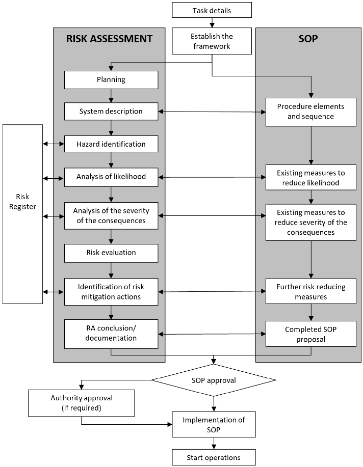
GM1 SPO.OP.230 Standard operating procedures
ED Decision 2014/018/R
TEMPLATE FORMS
Figure 1 — Development of a SOP based on a risk assessment
Template Form A — Risk assessment (RA)
Date:RA of Responsible: |
Purpose: |
Type of operation and brief description: |
Participants, working group: |
Preconditions, assumptions and simplifications: |
Data used: |
Description of the analysis method: |
External context: |
•Regulatory requirements •Approvals •Environmental conditions (visibility, wind, turbulence, contrast, light, elevation, etc. unless evident from the SOPs) •Stakeholders and their potential interest |
Internal context: |
•Type(s) of aircraft •Personnel and qualifications •Combination/similarity with other operations/SOPs •Other RA used/considered/plugged in |
Existing barriers and emergency preparedness: |
Monitoring and follow up: |
Description of the risk: |
Risk evaluation: |
Conclusions: |
Template Form B — Hazard identification (HI)
Date: ………………………………..HI of …………………………… Responsible: ………………………………………………
Phase of operation | Hazard ref | Hazard | Causes | Existing controls | Controls ref | Comments |
Note:
Haz ref:A unique number for hazards, e.g. for use in a database
Controls ref: A unique number for the existing controls
Template Form C — Mitigating measures
Date: ………………..................... RA of ……………………… Responsible: ………………………………………………
Phase of operation | Haz ref | Consequence | Existing mitigation actions | Mitigation ref | L | S | Further mitigation required |
Note:
Haz ref: A unique number for hazards, e.g. for use in a database
Mitigation ref: A unique number for the mitigation actions
L: Likelihood
S:Severity
Template register A — risk register
Ref | Operation/ Procedure | Ref | Hazard | Ref | Consequences | Mitigation actions | L | S | Monitoring |
Note:
L: Likelihood
S: Severity
SPO.OP.235 EFVS 200 operations
Regulation (EU) 2021/2237
(a)An operator that intends to conduct EFVS 200 operations with operational credits and without a specific approval shall ensure that:
(1)the aircraft is certified for the intended operations;
(2)only runways, FATOs and IAPs suitable for EFVS operations are used;
(3)the flight crew are competent to conduct the intended operation and a training and checking programme for the flight crew members and relevant personnel involved in the flight preparation is established;
(4)operating procedures are established;
(5)any relevant information is documented in the minimum equipment list (MEL);
(6)any relevant information is documented in the maintenance programme;
(7)safety assessments are carried out and performance indicators are established to monitor the level of safety of the operation; and
(8)the aerodrome operating minima take into account the capability of the system used.
(b)The operator shall not conduct EFVS 200 operations when conducting LVOs.
(c)Notwithstanding point (a)(1), the operator may use EVSs meeting the minimum criteria to conduct EFVS 200 operations, provided that this is approved by the competent authority.
GM1 SPO.OP.235 EFVS 200 operations
ED Decision 2022/012/R
GENERAL
(a)EFVS operations exploit the improved visibility provided by the EFVS to extend the visual segment of an instrument approach. EFVSs cannot be used to extend the instrument segment of an approach and thus the DH for EFVS 200 operations is always the same as for the same approach conducted without EFVS.
(b)Equipment for EFVS 200 operations
(1)In order to conduct EFVS 200 operations, a certified EFVS is used (EFVS-A or EFVS-L). An EFVS is an enhanced vision system (EVS) that also incorporates a flight guidance system and displays the image on a HUD or equivalent display. The flight guidance system will incorporate aircraft flight information and flight symbology.
(2)In multi-pilot operations, a suitable display of EFVS sensory imagery is provided to the pilot monitoring.
(c)Suitable approach procedures
(1)Types of approach operation are specified in AMC1 SPO.OP.235(a)(2).
EFVS 200 operations are used for 3D approach operations. This may include operations based on NPA procedures, approach procedures with vertical guidance and PA procedures including approach operations requiring specific approvals, provided that the operator holds the necessary approvals.
(2)Offset approaches
Refer to AMC1 SPO.OP.235(a)(2).
(3)Circling approaches
EFVSs incorporate a HUD or an equivalent system so that the EFVS image of the scene ahead of the aircraft is visible in the pilot’s forward external FOV. Circling operations require the pilot to maintain visual references that may not be directly ahead of the aircraft and may not be aligned with the current flight path. EFVSs cannot therefore be used in place of natural visual reference for circling approaches.
(d)Aerodrome operating minima for EFVS 200 operations are determined in accordance with AMC1 SPO.OP.235(a)(8).
The performance of EFVSs depends on the technology used and weather conditions encountered. Table 1 ‘Operations utilising EFVS: RVR reduction’ has been developed after an operational evaluation of two different EVSs, both using infrared sensors, along with data and support provided by the FAA. Approaches were flown in a variety of conditions including fog, rain and snow showers, as well as at night to aerodromes located in mountainous terrain. Table 1 contains conservative figures to cater for the expected performance of infrared sensors in the variety of conditions that might be encountered. Some systems may have better capability than those used for the evaluation, but credit cannot be taken for such performance in EFVS 200 operations.
(e)The conditions for commencement and continuation of the approach are in accordance with SPO.OP.215.
Pilots conducting EFVS 200 operations may commence an approach and continue that approach below 1 000 ft above the aerodrome or into the FAS if the reported RVR or CMV is equal to or greater than the lowest RVR minima determined in accordance with AMC1 SPO.OP.235(a)(8) and if all the conditions for the conduct of EFVS 200 operations are met.
Should any equipment required for EFVS 200 operations be unserviceable or unavailable, the conditions to conduct EFVS 200 operations would not be satisfied, and the approach should not be commenced. In the event of failure of the equipment required for EFVS 200 operations after the aircraft descends below 1 000 ft above the aerodrome or into the FAS, the conditions of SPO.OP.230 would no longer be satisfied unless the RVR reported prior to commencement of the approach was sufficient for the approach to be flown without the use of EFVS in lieu of natural vision.
(f)EFVS image requirements at the DA/H are specified in AMC1 SPO.OP.235(a)(4).
The requirements for features to be identifiable on the EFVS image in order to continue approach below the DH are more stringent than the visual reference requirements for the same approach flown without EFVS. The more stringent standard is needed because the EFVS might not display the colour of lights used to identify specific portions of the runway and might not consistently display the runway markings. Any visual approach path indicator using colourcoded lights may be unusable.
(g)Obstacle clearance in the visual segment
The ‘visual segment’ is the portion of the approach between the DH or the MAPt and the runway threshold. In the case of EFVS 200 operations, this part of the approach may be flown using the EFVS image as the primary reference and obstacles may not always be identifiable on an EFVS image. The operational assessment specified in AMC1 SPO.OP.235(a)(2) is therefore required to ensure obstacle clearance during the visual segment.
(h)Visual reference requirements at 200 ft above the threshold
For EFVS 200 operations, natural visual reference is required by a height of 200 ft above the runway threshold. The objective of this requirement is to ensure that the pilot will have sufficient visual reference to land. The visual reference should be the same as that required for the same approach flown without the use of EFVS.
Some EFVSs may have additional requirements that have to be fulfilled at this height to allow the approach to continue, such as a requirement to check that elements of the EFVS display remain correctly aligned and scaled to the external view. Any such requirements will be detailed in the AFM and included in the operator’s procedures.
(i)Specific approval for EFVS
In order to use EFVS without natural visual reference below 200 ft above the threshold, the operator needs to hold a specific approval in accordance with Part-SPA.
(j)Go-around
A go-around will be promptly executed if the required visual references are not maintained on the EFVS image at any time after the aircraft has descended below the DA/H or if the required visual references are not distinctly visible and identifiable using natural vision after the aircraft is below 200 ft. It is considered more likely that an EFVS 200 operation could result in the initiation of a go-around below the DA/H than the equivalent approach flown without EFVS and thus the operational assessment required by AMC1 SPO.OP.235(a)(2) takes into account the possibility of a balked landing.
An obstacle free zone (OFZ) may also be provided for CAT I PA procedures. Where an OFZ is not provided for a CAT I precision approach, this will be indicated on the approach chart. NPA procedures and approach procedures with vertical guidance provide obstacle clearance for the missed approach based on the assumption that a go-around is executed at the MAPt and not below the MDH.
AMC1 SPO.OP.235(a)(1) EFVS 200 operations
ED Decision 2022/012/R
EQUIPMENT CERTIFICATION
For EFVS 200 operations, the aircraft should be equipped with an approach system using EFVS-A or a landing system using EFVS-L.
AMC1 SPO.OP.235(a)(2) EFVS 200 operations
ED Decision 2022/012/R
AERODROMES AND INSTRUMENT PROCEDURES SUITABLE FOR EFVS 200 OPERATIONS
(a)For EFVS 200 operations, the operator should verify the suitability of a runway before authorising EFVS operations to that runway through an operational assessment taking into account the following elements:
(1)the obstacle situation;
(2)the type of aerodrome lighting;
(3)the available IAPs;
(4)the aerodrome operating minima; and
(5)any non-standard conditions that may affect the operations.
(b)EFVS 200 operations should only be conducted as 3D operations, using an IAP in which the final approach track is offset by a maximum of 3 degrees from the extended centre line of the runway.
(c)The IAP should be designed in accordance with PANS-OPS, Volume I (ICAO Doc 8168) or equivalent criteria.
AMC2 SPO.OP.235(a)(2) EFVS 200 operations
ED Decision 2022/014/R
VERIFICATION OF THE SUITABILITY OF RUNWAYS FOR EFVS 200 OPERATIONS
The operational assessment before authorising the use of a runway for EFVS 200 operations may be conducted as follows:
(a)Check whether the runway has been promulgated as suitable for EFVS 200 operations or is certified as a PA category II or III runway by the State of the aerodrome. If this is so, then check whether and where the approach and runway lights installed (notably incandescent or LED lights) are adequate for the EFVS equipment used by the operator.
(b)If the check in point (a) above comes out negative (the runway is not promulgated as EFVS suitable or is not category II or III), then proceed as follows:
(1)For straight-in IAPs, US Standard for Terminal Instrument Procedures (TERPS) may be considered to be acceptable as an equivalent to PANS-OPS. If other design criteria than PANSOPS or US TERPS are used, the operations should not be conducted.
(2)If an OFZ is established, this will ensure adequate obstacle protection from 960 m before the threshold. If an OFZ is not established or if the DH for the approach is above 250 ft, then check whether there is a visual segment surface (VSS).
(3)VSSs are required for procedures published after 15 March 2007, but the existence of the VSS has to be verified through an aeronautical information publication (AIP), operations manual Part C, or direct contact with the aerodrome. Where the VSS is established, it may not be penetrated by obstacles. If the VSS is not established or is penetrated by obstacles and an OFZ is not established, then the operations should not be conducted. Note: obstacles of a height of less than 50 ft above the threshold may be disregarded when assessing the VSS.
(4)Runways with obstacles that require visual identification and avoidance should not be accepted.
(5)For the obstacle protection of a balked landing where an OFZ is not established, the operator may specify that pilots follow a departure procedure in the event of a balked landing, in which case it is necessary to verify that the aircraft will be able to comply with the climb gradients published for the instrument departure procedures for the expected landing conditions.
(6)Perform an assessment of the suitability of the runway which should include whether the approach and runway lights installed (notably incandescent or LED lights) are adequate for the EFVS equipment used by the operator.
(c)If the AFM stipulates specific requirements for approach procedures, then the operational assessment should verify that these requirements can be met.