
Filters
GM8 CAT.OP.MPA.110 Aerodrome operating minima
ED Decision 2023/007/R
LOW TEMPERATURE CORRECTION
(a)An operator may determine the aerodrome temperature below which a correction should be applied to the DA/H.
(b)Table 20 may be used to determine the correction that should be applied.
(c)The calculations in the table are for a sea-level aerodrome; they are therefore conservative when applied at higher-level aerodromes.
(d)Guidance on accurate corrections for specific conditions (if required) is available in PANS-OPS, Volume III (ICAO Doc 8168) Section 2 Chapter 4 First Edition, 2018.
Table 20
Temperature corrections to be applied to barometric DH/MDH
Aerodrome temperature | Height above the elevation of the altimeter setting source (ft) | |||||||||||||
200 | 300 | 400 | 500 | 600 | 700 | 800 | 900 | 1 000 | 1 500 | 2 000 | 3 000 | 4 000 | 5 000 | |
0 | 20 | 20 | 30 | 30 | 40 | 40 | 50 | 50 | 60 | 90 | 120 | 170 | 230 | 280 |
-10 | 20 | 30 | 40 | 50 | 60 | 70 | 80 | 90 | 100 | 150 | 200 | 290 | 390 | 490 |
-20 | 30 | 50 | 60 | 70 | 90 | 100 | 120 | 130 | 140 | 210 | 280 | 420 | 570 | 710 |
-30 | 40 | 60 | 80 | 100 | 120 | 140 | 150 | 170 | 190 | 280 | 380 | 570 | 760 | 950 |
-40 | 50 | 80 | 100 | 120 | 150 | 170 | 190 | 220 | 240 | 360 | 480 | 720 | 970 | 1 210 |
-50 | 60 | 90 | 120 | 150 | 180 | 210 | 240 | 270 | 300 | 450 | 590 | 890 | 1 190 | 1 500 |
GM9 CAT.OP.MPA.110 Aerodrome operating minima
ED Decision 2022/012/R
AERODROME OPERATING MINIMA — HELICOPTERS
High vertical speeds should be avoided due to unstable aerodynamics and potential transient autorotation state of the main rotor.
Vertical speeds at or below 800 ft/min should be considered to be normal, and vertical speeds above 1 000 ft/min should be considered to be high.
The vertical speed on final approach increases with the descent angle and the ground speed (GS), including tailwinds. Whereas the helicopter should be manoeuvred into the wind during the visual segment of an instrument approach, tailwinds may be encountered during the instrument segments of the approach.
If the vertical speed is above 1 000 ft/min, a go-around should be considered. Greater vertical speeds may be used based on the available data in the rotorcraft flight manual.
Table 21 below gives an indication of the vertical speed based on the descent angles and ground speed.
Table 21
Examples of vertical speeds
Ground speed | Descent angle | Vertical speed |
80 kt | 5.7° (10 %) | 800 ft/min |
100 kt | 5.7° (10 %) | 1 000 ft/min |
80 kt | 7.5° (13.2 %) | 1 050 ft/min |
100 kt | 7.5° (13.2 %) | 1 300 ft/min |
Note: A GS of 80 kt may be the result of an indicated airspeed (IAS) of 60 kt and a tailwind component of 20 kt.
GM1 CAT.OP.MPA.110(b)(6) Aerodrome operating minima
ED Decision 2022/012/R
VISUAL AND NON-VISUAL AIDS AND INFRASTRUCTURE
‘Visual and non-visual aids and infrastructure’ refers to all equipment and facilities required for the procedure to be used for the intended instrument approach operation. This includes but is not limited to lights, markings, ground- or space-based radio aids, etc.
CAT.OP.MPA.115 Approach flight technique — aeroplanes
Regulation (EU) 2021/2237
(a)All approach operations shall be flown as stabilised approach operations unless otherwise approved by the competent authority for a particular approach to a particular runway.
(b)The continuous descent final approach (CDFA) technique shall be used for approach operations using non-precision approach (NPA) procedures except for such particular runways for which the competent authority has approved another flight technique.
AMC1 CAT.OP.MPA.115 Approach flight technique — aeroplanes
ED Decision 2022/012/R
CONTINUOUS DESCENT FINAL APPROACH (CDFA)
The following criteria apply to CDFA:
(a)For each NPA procedure to be used, the operator should provide information allowing the flight crew to determine the appropriate descent path. This information is either:
(1)a descent path depicted on the approach chart including check altitude/heights against range;
(2)a descent path coded into the aircraft flight management system; or
(3)a recommended descent rate based on estimated ground speed.
(b)The information provided to the crew should observe human factors principles.
(c)The descent path should be calculated to pass at or above the minimum altitude specified at any step-down fix.
(d)The optimum angle for the descent path is 3° and should not exceed 4,5° except for steep approach operations approved in accordance with this Part.
(e)For multi-pilot operations, the operator should establish procedures that require:
(1)the pilot monitoring to verbalise deviations from the required descent path;
(2)the pilot flying to make prompt corrections to deviation from the required descent path; and
(3)a call-out to be made when the aircraft is approaching the DA/H.
(f)A missed approach should be executed promptly at the DA/H or the MAPt, whichever is first, if the required visual references have not been established.
(g)For approaches other than circling approaches, the lateral part of the missed approach should be flown via the MAPt unless otherwise stated on the approach chart.
AMC2 CAT.OP.MPA.115 Approach flight technique — aeroplanes
ED Decision 2022/012/R
APPROACH OPERATIONS USING NPA PROCEDURES FLOWN WITH A FLIGHT TECHNIQUE OTHER THAN THE CDFA
(a)In case the CDFA technique is not used, the approach should be flown to an altitude/height at or above the MDA/H where a level flight segment at or above MDA/H may be flown to the MAPt.
(b)Even when the approach procedure is flown without the CDFA technique, the relevant procedures for ensuring a controlled and stable path to MDA/H should be followed.
(c)In case the CDFA technique is not used when flying an approach, the operator should implement procedures to ensure that early descent to the MDA/H will not result in a subsequent flight below MDA/H without adequate visual reference. These procedures could include:
(1)awareness of radio altimeter information with reference to the approach profile;
(2)terrain awareness warning system (TAWS);
(3)limitation of rate of descent;
(4)limitation of the number of repeated approaches;
(5)safeguards against too early descents with prolonged flight at MDA/H; and
(6)specification of visual requirements for the descent from the MDA/H.
(d)In case the CDFA technique is not used and when the MDA/H is high, it may be appropriate to make an early descent to MDA/H with appropriate safeguards such as the application of a significantly higher RVR or VIS.
(e)The procedures that are flown with level flight at or above the MDA/H should be listed in the OM.
(f)Operators should categorise aerodromes where there are approaches that require level flight at or above MDA/H as B or C. Such aerodrome categorisation will depend upon the operator’s experience, operational exposure, training programme(s) and flight crew qualification(s).
AMC3 CAT.OP.MPA.115 Approach flight technique — aeroplanes
ED Decision 2022/012/R
OPERATIONAL PROCEDURES AND INSTRUCTIONS AND TRAINING
(a)The operator should establish procedures and instructions for flying approaches using the CDFA technique and not using it. These procedures should be included in the operations manual and should include the duties of the flight crew during the conduct of such operations. The operator should ensure that the initial and recurrent flight crew training required by ORO.FC includes the use of the CDFA technique.
(b)Operators holding an approval to use another technique for NPAs on certain runways should establish procedures for the application of such techniques.
AMC1 CAT.OP.MPA.115(a) Approach flight technique — aeroplanes
ED Decision 2022/014/R
STABILISED APPROACH OPERATIONS — AEROPLANES
The following criteria should be satisfied for all stabilised approach operations with aeroplanes:
(a)The flight management systems and approach aids should be correctly set, and any required radio aids identified before reaching a predetermined point or altitude/height on the approach.
(b)The aeroplane should be flown according to the following criteria from a predetermined point or altitude/height on the approach:
(1)the angle of bank should be less than 30 degrees; and
(2)the target rate of descent should be that required to maintain the correct vertical path at the planned approach speed.
(c)Variations in the rate of descent should normally not exceed 50 % of the target rate of descent.
(d)An aeroplane should be considered stabilised for landing when the following conditions are met:
(1)the aeroplane is tracking within an acceptable tolerance of the required lateral path;
(2)the aeroplane is tracking within an acceptable tolerance of the required vertical path;
(3)the vertical speed of the aeroplane is within an acceptable tolerance of the required rate of descent;
(4)the airspeed of the aeroplane is within an acceptable tolerance of the intended landing speed;
(5)the aeroplane is in the correct configuration for landing, unless operating procedures require a final configuration change for performance reasons after visual reference is acquired; and
(6)the thrust/power and trim settings are appropriate.
(e)The aeroplane should be stabilised for landing before reaching 500 ft above the landing runway threshold elevation.
(f)For approach operations where the pilot does not have visual reference with the ground, the aeroplane should additionally be stabilised for landing before reaching 1 000 ft above the landing runway threshold elevation except that a later stabilisation in airspeed may be acceptable if higher than normal approach speeds are required for operational reasons specified in the operations manual.
(g)The operator should specify the following in the operations manual:
(1)the acceptable tolerances referred to in (d);
(2)the means to identify the predetermined points referred to in (a) and (b). This should normally be the FAF.
(h)When the operator requests approval for an alternative to the stabilised approach criteria for a particular approach to a particular runway, the operator should demonstrate that the proposed alternative will ensure that an acceptable level of safety is achieved.
GM1 CAT.OP.MPA.115(a) Approach flight techniques — aeroplanes
ED Decision 2022/012/R
ACCEPTABLE TOLERANCES FOR STABILISED APPROACH OPERATIONS
(a)The requirement for the aircraft to be tracking within an acceptable tolerance of the required lateral path does not imply that the aircraft has to be aligned with the runway centre line by any particular height.
(b)The target rate of descent for the final approach segment (FAS) of a stabilised approach normally does not exceed 1 000 fpm. Where a rate of descent of more than 1 000 fpm will be required (e.g. due to high ground speed or a steeper-than-normal approach path), this should be briefed in advance.
(c)Operational reasons for specifying a higher-than-normal approach speed below 1 000 ft may include compliance with air traffic control (ATC) speed restrictions.
(d)For operations where a level flight segment is required during the approach (e.g. circling approaches or approaches flown as non-CDFA), the criteria in point (b) of AMC1 CAT.OP.MPA.115(a) should apply from the predetermined point until the start of the level flight segment and again from the point at which the aircraft begins descent from the level flight segment down to a point of 50 ft above the threshold or the point where the flare manoeuvre is initiated, if higher.
GM1 CAT.OP.MPA.115(b) Approach flight technique — aeroplanes
ED Decision 2022/012/R
CONTINUOUS DESCENT FINAL APPROACH (CDFA)
(a)Introduction
(1)Controlled flight into terrain (CFIT) is a major hazard in aviation. Most CFIT accidents occur in the FAS of approach operations flown using the NPA procedures. The use of stabilised-approach criteria on a continuous descent with a constant, predetermined vertical path is seen as a major improvement in safety during the conduct of such approaches.
(2)The elimination of level flight segments at MDA close to the ground during approaches, and the avoidance of major changes in attitude and power/thrust close to the runway that can destabilise approaches, are seen as ways to reduce operational risks significantly.
(3)The term CDFA has been selected to cover a flight technique for instrument approach operations using NPA procedures.
(4)The advantages of CDFA are as follows:
(i)the technique enhances safe approach operations by the utilisation of standard operating practices;
(ii)the technique is similar to that used when flying an ILS approach, including when executing the missed approach and the associated missed approach procedure manoeuvre;
(iii)the aeroplane attitude may enable better acquisition of visual cues;
(iv)the technique may reduce pilot workload;
(v)the approach profile is fuel-efficient;
(vi)the approach profile affords reduced noise levels;
(vii)the technique affords procedural integration with 3D approach operations; and
(viii)when used and the approach is flown in a stabilised manner, CDFA is the safest approach technique for all instrument approach operations using NPA procedures.
(b)Stabilised approach (SAp)
(1)The control of the descent path is not the only consideration when using the CDFA technique. Control of the aeroplane’s configuration and energy is also vital to the safe conduct of an approach.
(2)The control of the flight path, described above as one of the specifications for conducting an SAp, should not be confused with the path specifications for using the CDFA technique. The predetermined path specification for conducting an SAp are established by the operator and published in the operations manual.
(3)The appropriate descent path for applying the CDFA technique is established by the following:
(A)the published ‘nominal’ slope information when the approach has a nominal vertical profile; and
(B)the designated final-approach segment minimum of 3 NM, and maximum, when using timing techniques, of 8 NM.
(4)Straight-in approach operations using CDFA do not have a level segment of flight at MDA/H. This enhances safety by mandating a prompt missed approach procedure manoeuvre at DA/H.
(5)An approach using the CDFA technique is always flown as an SAp, since this is a specification for applying CDFA. However, an SAp does not have to be flown using the CDFA technique, for example, a visual approach.
(c)Circling approach operations using the CDFA technique
Circling approach operations using the CDFA technique require a continuous descent from an altitude/height at or above the FAF altitude/height until MDA/H or visual flight manoeuvre altitude/height. This does not preclude level flight at or above the MDA/H. This level flight may be at MDA/H while following the IAP or after visual reference has been established as the aircraft is aligned with the final approach track. The conditions for descent from level flight are described in AMC7 CAT.OP.MPA.110.
CAT.OP.MPA.125 Instrument departure and approach procedures
Regulation (EU) No 965/2012
(a)The operator shall ensure that instrument departure and approach procedures established by the State of the aerodrome are used.
(b)Notwithstanding (a), the commander may accept an ATC clearance to deviate from a published departure or arrival route, provided obstacle clearance criteria are observed and full account is taken of the operating conditions. In any case, the final approach shall be flown visually or in accordance with the established instrument approach procedures.
(c)Notwithstanding (a), the operator may use procedures other than those referred to in (a) provided they have been approved by the State in which the aerodrome is located and are specified in the operations manual.
CAT.OP.MPA.126 Performance-based navigation
Regulation (EU) 2016/1199
The operator shall ensure that, when performance-based navigation (PBN) is required for the route or procedure to be flown:
(a)the relevant PBN navigation specification is stated in the AFM or other document that has been approved by the certifying authority as part of an airworthiness assessment or is based on such approval; and
(b)the aircraft is operated in conformance with the relevant navigation specification and limitations in the AFM or other document referred above.
AMC1 CAT.OP.MPA.126 Performance-based navigation
ED Decision 2016/015/R
PBN OPERATIONS
For operations where a navigation specification for performance-based navigation (PBN) has been prescribed and no specific approval is required in accordance with SPA.PBN.100, the operator should:
(a)establish operating procedures specifying:
(1)normal, abnormal and contingency procedures;
(2)electronic navigation database management; and
(3)relevant entries in the minimum equipment list (MEL);
(b)specify the flight crew qualification and proficiency constraints and ensure that the training programme for relevant personnel is consistent with the intended operation; and
(c)ensure continued airworthiness of the area navigation system.
AMC2 CAT.OP.MPA.126 Performance-based navigation
ED Decision 2022/012/R
MONITORING AND VERIFICATION
(a)Preflight and general considerations
(1)At navigation system initialisation, the flight crew should confirm that the navigation database is current and verify that the aircraft position has been entered correctly, if required.
(2)The active flight plan, if applicable, should be checked by comparing the charts or other applicable documents with navigation equipment and displays. This includes confirmation of the departing runway and the waypoint sequence, reasonableness of track angles and distances, any altitude or speed constraints, and, where possible, which waypoints are fly-by and which are fly-over. Where relevant, the RF leg arc radii should be confirmed.
(3)The flight crew should check that the navigation aids critical to the operation of the intended PBN procedure are available.
(4)The flight crew should confirm the navigation aids that should be excluded from the operation, if any.
(5)An arrival, approach or departure procedure should not be used if the validity of the procedure in the navigation database has expired.
(6)The flight crew should verify that the navigation systems required for the intended operation are operational.
(b)Departure
(1)Prior to commencing a take-off on a PBN procedure, the flight crew should check that the indicated aircraft position is consistent with the actual aircraft position at the start of the take-off roll (aeroplanes) or lift-off (helicopters).
(2)Where GNSS is used, the signal should be acquired before the take-off roll (aeroplanes) or lift-off (helicopters) commences.
(3)Unless automatic updating of the actual departure point is provided, the flight crew should ensure initialisation on the runway or FATO by means of a manual runway threshold or intersection update, as applicable. This is to preclude any inappropriate or inadvertent position shift after take-off.
(c)Arrival and approach
(1)The flight crew should verify that the navigation system is operating correctly and the correct arrival procedure and runway (including any applicable transition) are entered and properly depicted.
(2)Any published altitude and speed constraints should be observed.
(3)The flight crew should check approach procedures (including alternate aerodromes if needed) as extracted by the system (e.g. CDU flight plan page) or presented graphically on the moving map, in order to confirm the correct loading and the reasonableness of the procedure content.
(4)Prior to commencing the approach operation (before the IAF), the flight crew should verify the correctness of the loaded procedure by comparison with the appropriate approach charts. This check should include:
(i)the waypoint sequence;
(ii)reasonableness of the tracks and distances of the approach legs and the accuracy of the inbound course; and
(iii)the vertical path angle, if applicable.
(d)Altimetry settings for RNP APCH operations using Baro VNAV
(1)Barometric settings
(i)The flight crew should set and confirm the correct altimeter setting and check that the two altimeters provide altitude values that do not differ more than 100 ft at the most at or before the final approach fix (FAF).
(ii)The flight crew should fly the procedure with:
(A)a current local altimeter setting source available — a remote or regional altimeter setting source should not be used; and
(B)the QNH/QFE, as appropriate, set on the aircraft’s altimeters.
(2)Temperature compensation
(i)For RNP APCH operations to LNAV/VNAV minima using Baro VNAV:
(A)the flight crew should not commence the approach when the aerodrome temperature is outside the promulgated aerodrome temperature limits for the procedure unless the area navigation system is equipped with approved temperature compensation for the final approach;
(B)when the temperature is within promulgated limits, the flight crew should not make compensation to the altitude at the FAF;
(C)since only the final approach segment is protected by the promulgated aerodrome temperature limits, the flight crew should consider the effect of temperature on terrain and obstacle clearance in other phases of flight.
(ii)For RNP APCH operations to LNAV minima, the flight crew should consider the effect of temperature on terrain and obstacle clearance in all phases of flight, in particular on any step-down fix.
(e)Sensor and lateral navigation accuracy selection
(1)For multi-sensor systems, the flight crew should verify, prior to approach, that the GNSS sensor is used for position computation.
(2)Flight crew of aircraft with RNP input selection capability should confirm that the indicated RNP value is appropriate for the PBN operation.
AMC3 CAT.OP.MPA.126 Performance-based navigation
ED Decision 2016/015/R
MANAGEMENT OF THE NAVIGATION DATABASE
(a)For RNAV 1, RNAV 2, RNP 1, RNP 2, and RNP APCH, the flight crew should neither insert nor modify waypoints by manual entry into a procedure (departure, arrival or approach) that has been retrieved from the database. User-defined data may be entered and used for waypoint altitude/speed constraints on a procedure where said constraints are not included in the navigation database coding.
(b)For RNP 4 operations, the flight crew should not modify waypoints that have been retrieved from the database. User-defined data (e.g. for flex-track routes) may be entered and used.
(c)The lateral and vertical definition of the flight path between the FAF and the missed approach point (MAPt) retrieved from the database should not be revised by the flight crew.
AMC4 CAT.OP.MPA.126 Performance-based navigation
ED Decision 2016/015/R
DISPLAYS AND AUTOMATION
(a)For RNAV 1, RNP 1, and RNP APCH operations, the flight crew should use a lateral deviation indicator, and where available, flight director and/or autopilot in lateral navigation mode.
(b)The appropriate displays should be selected so that the following information can be monitored:
(1)the computed desired path;
(2)aircraft position relative to the lateral path (cross-track deviation) for FTE monitoring;
(3)aircraft position relative to the vertical path (for a 3D operation).
(c)The flight crew of an aircraft with a lateral deviation indicator (e.g. CDI) should ensure that lateral deviation indicator scaling (full-scale deflection) is suitable for the navigation accuracy associated with the various segments of the procedure.
(d)The flight crew should maintain procedure centrelines unless authorised to deviate by air traffic control (ATC) or demanded by emergency conditions.
(e)Cross-track error/deviation (the difference between the area-navigation-system-computed path and the aircraft-computed position) should normally be limited to ± ½ time the RNAV/RNP value associated with the procedure. Brief deviations from this standard (e.g. overshoots or undershoots during and immediately after turns) up to a maximum of 1 time the RNAV/RNP value should be allowable.
(f)For a 3D approach operation, the flight crew should use a vertical deviation indicator and, where required by AFM limitations, a flight director or autopilot in vertical navigation mode.
(g)Deviations below the vertical path should not exceed 75 ft at any time, or half-scale deflection where angular deviation is indicated, and not more than 75 ft above the vertical profile, or half-scale deflection where angular deviation is indicated, at or below 1 000 ft above aerodrome level. The flight crew should execute a missed approach if the vertical deviation exceeds this criterion, unless the flight crew has in sight the visual references required to continue the approach.
AMC5 CAT.OP.MPA.126 Performance-based navigation
ED Decision 2016/015/R
VECTORING AND POSITIONING
(a)ATC tactical interventions in the terminal area may include radar headings, ‘direct to’ clearances which bypass the initial legs of an approach procedure, interceptions of an initial or intermediate segments of an approach procedure or the insertion of additional waypoints loaded from the database.
(b)In complying with ATC instructions, the flight crew should be aware of the implications for the navigation system.
(c)‘Direct to’ clearances may be accepted to the IF provided that it is clear to the flight crew that the aircraft will be established on the final approach track at least 2 NM before the FAF.
(d)‘Direct to’ clearance to the FAF should not be acceptable. Modifying the procedure to intercept the final approach track prior to the FAF should be acceptable for radar-vectored arrivals or otherwise only with ATC approval.
(e)The final approach trajectory should be intercepted no later than the FAF in order for the aircraft to be correctly established on the final approach track before starting the descent (to ensure terrain and obstacle clearance).
(f)‘Direct to’ clearances to a fix that immediately precede an RF leg should not be permitted.
(g)For parallel offset operations en route in RNP 4 and A-RNP, transitions to and from the offset track should maintain an intercept angle of no more than 45° unless specified otherwise by ATC.
AMC6 CAT.OP.MPA.126 Performance-based navigation
ED Decision 2016/015/R
ALERTING AND ABORT
(a)Unless the flight crew has sufficient visual reference to continue the approach operation to a safe landing, an RNP APCH operation should be discontinued if:
(1)navigation system failure is annunciated (e.g. warning flag);
(2)lateral or vertical deviations exceed the tolerances;
(3)loss of the on-board monitoring and alerting system.
(b)Discontinuing the approach operation may not be necessary for a multi-sensor navigation system that includes demonstrated RNP capability without GNSS in accordance with the AFM.
(c)Where vertical guidance is lost while the aircraft is still above 1 000 ft AGL, the flight crew may decide to continue the approach to LNAV minima, when supported by the navigation system.
AMC7 CAT.OP.MPA.126 Performance-based navigation
ED Decision 2016/015/R
CONTINGENCY PROCEDURES
(a)The flight crew should make the necessary preparation to revert to a conventional arrival procedure where appropriate. The following conditions should be considered:
(1)failure of the navigation system components including navigation sensors, and a failure effecting flight technical error (e.g. failures of the flight director or autopilot);
(2)multiple system failures affecting aircraft performance;
(3)coasting on inertial sensors beyond a specified time limit; and
(4)RAIM (or equivalent) alert or loss of integrity function.
(b)In the event of loss of PBN capability, the flight crew should invoke contingency procedures and navigate using an alternative means of navigation.
(c)The flight crew should notify ATC of any problem with PBN capability.
(d)In the event of communication failure, the flight crew should continue with the operation in accordance with published lost communication procedures.
GM1 CAT.OP.MPA.126 Performance-based navigation
ED Decision 2016/015/R
DESCRIPTION
(a)For both, RNP X and RNAV X designations, the ‘X’ (where stated) refers to the lateral navigation accuracy (total system error) in NM, which is expected to be achieved at least 95 % of the flight time by the population of aircraft operating within the airspace, route or procedure. For RNP APCH and A-RNP, the lateral navigation accuracy depends on the segment.
(b)PBN may be required on notified routes, for notified procedures and in notified airspace.
RNAV 10
(c)For purposes of consistency with the PBN concept, this Regulation is using the designation ‘RNAV 10’ because this specification does not include on-board performance monitoring and alerting.
(d)However, it should be noted that many routes still use the designation ‘RNP 10’ instead of ‘RNAV 10’. ‘RNP 10’ was used as designation before the publication of the fourth edition of ICAO Doc 9613 in 2013. The terms ‘RNP 10’ and ‘RNAV 10’ should be considered equivalent.
CAT.OP.MPA.130 Noise abatement procedures — aeroplanes
Regulation (EU) 2015/140
(a)Except for VFR operations of other-than complex motor-powered aeroplanes, the operator shall establish appropriate operating departure and arrival/approach procedures for each aeroplane type taking into account the need to minimise the effect of aircraft noise.
(b)The procedures shall:
(1)ensure that safety has priority over noise abatement; and
(2)be simple and safe to operate with no significant increase in crew workload during critical phases of flight.
AMC1 CAT.OP.MPA.130 Noise abatement procedures — aeroplanes
ED Decision 2014/015/R
NADP DESIGN
(a)For each aeroplane type, two departure procedures should be defined, in accordance with ICAO Doc 8168 (Procedures for Air Navigation Services, ‘PANS-OPS’), Volume I:
(1)noise abatement departure procedure one (NADP 1), designed to meet the close-in noise abatement objective; and
(2)noise abatement departure procedure two (NADP 2), designed to meet the distant noise abatement objective.
(b)For each type of NADP (1 and 2), a single climb profile should be specified for use at all aerodromes, which is associated with a single sequence of actions. The NADP 1 and NADP 2 profiles may be identical.
GM1 CAT.OP.MPA.130 Noise abatement procedures — aeroplanes
ED Decision 2014/015/R
TERMINOLOGY
(a)‘Climb profile’ means in this context the vertical path of the NADP as it results from the pilot’s actions (engine power reduction, acceleration, slats/flaps retraction).
(b)‘Sequence of actions’ means the order in which these pilot’s actions are done and their timing.
GENERAL
(c)The rule addresses only the vertical profile of the departure procedure. Lateral track has to comply with the standard instrument departure (SID).
EXAMPLE
(d)For a given aeroplane type, when establishing the distant NADP, the operator should choose either to reduce power first and then accelerate, or to accelerate first and then wait until slats/flaps are retracted before reducing power. The two methods constitute two different sequences of actions.
(e)For an aeroplane type, each of the two departure climb profiles may be defined by one sequence of actions (one for close-in, one for distant) and two above aerodrome level (AAL) altitudes/heights. These are:
(1)the altitude of the first pilot’s action (generally power reduction with or without acceleration). This altitude should not be less than 800 ft AAL; or
(2)the altitude of the end of the noise abatement procedure. This altitude should usually not be more than 3 000 ft AAL.
These two altitudes may be runway specific when the aeroplane flight management system (FMS) has the relevant function which permits the crew to change thrust reduction and/or acceleration altitude/height. If the aeroplane is not FMS-equipped or the FMS is not fitted with the relevant function, two fixed heights should be defined and used for each of the two NADPs.
CAT.OP.MPA.131 Noise abatement procedures — helicopters
Regulation (EU) No 965/2012
(a)The operator shall ensure that take-off and landing procedures take into account the need to minimise the effect of helicopter noise.
(b)The procedures shall:
(1)ensure that safety has priority over noise abatement; and
(2)be simple and safe to operate with no significant increase in crew workload during critical phases of flight.
CAT.OP.MPA.135 Routes and areas of operation — general
Regulation (EU) 2016/1199
(a)The operator shall ensure that operations are only conducted along routes, or within areas, for which:
(1)space-based facilities, ground facilities and services, including meteorological services, adequate for the planned operation are provided;
(2)the performance of the aircraft is adequate to comply with minimum flight altitude requirements;
(3)the equipment of the aircraft meets the minimum requirements for the planned operation; and
(4)appropriate maps and charts are available.
(b)The operator shall ensure that operations are conducted in accordance with any restriction on the routes or the areas of operation specified by the competent authority.
(c)point (a)(1) shall not apply to operations under VFR by day of other-than complex motor-powered aircraft on flights that depart from and arrive at the same aerodrome or operating site.
AMC1 CAT.OP.MPA.135 Routes and areas of operation — general
ED Decision 2016/015/R
RNAV 10
(a)Operating procedures and routes should take account of the RNAV 10 time limit declared for the inertial system, if applicable, considering also the effect of weather conditions that could affect flight duration in RNAV 10 airspace.
(b)The operator may extend RNAV 10 inertial navigation time by position updating. The operator should calculate, using statistically-based typical wind scenarios for each planned route, points at which updates can be made, and the points at which further updates will not be possible.
CAT.OP.MPA.136 Routes and areas of operation — single-engined aeroplanes
Regulation (EU) 2017/363
Unless approved by the competent authority in accordance with Annex V (Part-SPA), Subpart L — SINGLE-ENGINED TURBINE AEROPLANE OPERATIONS AT NIGHT OR IN IMC (SET-IMC), the operator shall ensure that operations of single-engined aeroplanes are only conducted along routes, or within areas, where surfaces are available that permit a safe forced landing to be executed.
CAT.OP.MPA.137 Routes and areas of operation — helicopters
Regulation (EU) No 965/2012
The operator shall ensure that:
(a)for helicopters operated in performance class 3, surfaces are available that permit a safe forced landing to be executed, except when the helicopter has an approval to operate in accordance with CAT.POL.H.420;
(b)for helicopters operated in performance class 3 and conducting ‘coastal transit’ operations, the operations manual contains procedures to ensure that the width of the coastal corridor, and the equipment carried, is consistent with the conditions prevailing at the time.
GM1 CAT.OP.MPA.137(b) Routes and areas of operation — helicopters
ED Decision 2014/015/R
COASTAL TRANSIT
(a)General
(1)Helicopters operating overwater in performance class 3 have to have certain equipment fitted. This equipment varies with the distance from land that the helicopter is expected to operate. The aim of this GM is to discuss that distance, bring into focus what fit is required and to clarify the operator's responsibility, when a decision is made to conduct coastal transit operations.
(2)In the case of operations north of 45N or south of 45S, the coastal corridor facility may or may not be available in a particular state, as it is related to the State definition of open sea area as described in the definition of hostile environment.
(3)Where the term ‘coastal transit’ is used, it means the conduct of operations overwater within the coastal corridor in conditions where there is reasonable expectation that:
(i)the flight can be conducted safely in the conditions prevailing;
(ii)following an engine failure, a safe forced landing and successful evacuation can be achieved; and
(iii)survival of the crew and passengers can be assured until rescue is effected.
(4)Coastal corridor is a variable distance from the coastline to a maximum distance corresponding to three minutes’ flying at normal cruising speed.
(b)Establishing the width of the coastal corridor
(1)The maximum distance from land of coastal transit, is defined as the boundary of a corridor that extends from the land, to a maximum distance of up to 3 minutes at normal cruising speed (approximately 5 - 6 NM). Land in this context includes sustainable ice (see (i) to (iii) below) and, where the coastal region includes islands, the surrounding waters may be included in the corridor and aggregated with the coast and each other. Coastal transit need not be applied to inland waterways, estuary crossing or river transit.
(i)In some areas, the formation of ice is such that it can be possible to land, or force land, without hazard to the helicopter or occupants. Unless the competent authority considers that operating to, or over, such ice fields is unacceptable, the operator may regard that the definition of the ‘land’ extends to these areas.
(ii)The interpretation of the following rules may be conditional on (i) above:
—CAT.IDE.H.300; and
(iii)In view of the fact that such featureless and flat white surfaces could present a hazard and could lead to white-out conditions, the definition of land does not extend to flights over ice fields in the following rules:
—CAT.IDE.H.125(d); and
(2)The width of the corridor is variable from not safe to conduct operations in the conditions prevailing, to the maximum of 3 minutes wide. A number of factors will, on the day, indicate if it can be used — and how wide it can be. These factors will include, but not be restricted to, the following:
(i)meteorological conditions prevailing in the corridor;
(ii)instrument fit of the aircraft;
(iii)certification of the aircraft — particularly with regard to floats;
(iv)sea state;
(v)temperature of the water;
(vi)time to rescue; and
(vii)survival equipment carried.
(3)These can be broadly divided into three functional groups:
(i)those that meet the provisions for safe flying;
(ii)those that meet the provisions for a safe forced landing and evacuation; and
(iii)those that meet the provisions for survival following a forced landing and successful evacuation.
(c)Provision for safe flying
(1)It is generally recognised that when flying out of sight of land in certain meteorological conditions, such as those occurring in high pressure weather patterns (goldfish bowl — no horizon, light winds and low visibility), the absence of a basic panel (and training) can lead to disorientation. In addition, lack of depth perception in these conditions demands the use of a radio altimeter with an audio voice warning as an added safety benefit — particularly when autorotation to the surface of the water may be required.
(2)In these conditions, the helicopter, without the required instruments and radio altimeter, should be confined to a corridor in which the pilot can maintain reference using the visual cues on the land.
(d)Provision for a safe forced landing and evacuation
(1)Weather and sea state both affect the outcome of an autorotation following an engine failure. It is recognised that the measurement of sea state is problematical and when assessing such conditions, good judgement has to be exercised by the operator and the commander.
(2)Where floats have been certificated only for emergency use (and not for ditching), operations should be limited to those sea states that meet the provisions for such use — where a safe evacuation is possible.
Ditching certification requires compliance with a comprehensive number of requirements relating to rotorcraft water entry, flotation and trim, occupant egress and occupant survival. Emergency flotation systems, generally fitted to smaller CS-27 rotorcraft, are approved against a broad specification that the equipment should perform its intended function and not hazard the rotorcraft or its occupants. In practice, the most significant difference between ditching and emergency flotation systems is substantiation of the water entry phase. Ditching rules call for water entry procedures and techniques to be established and promulgated in the AFM. The fuselage/flotation equipment should thereafter be shown to be able to withstand loads under defined water entry conditions which relate to these procedures. For emergency flotation equipment, there is no specification to define the water entry technique and no specific conditions defined for the structural substantiation.
(e)Provisions for survival
(1)Survival of crew members and passengers, following a successful autorotation and evacuation, is dependent on the clothing worn, the equipment carried and worn, the temperature of the sea and the sea state. Search and rescue (SAR) response/capability consistent with the anticipated exposure should be available before the conditions in the corridor can be considered non-hostile.
(2)Coastal transit can be conducted (including north of 45N and south of 45S — when the definition of open sea areas allows) providing the provisions of (c) and (d) are met, and the conditions for a non-hostile coastal corridor are satisfied.
CAT.OP.MPA.140 Maximum distance from an adequate aerodrome for two-engined aeroplanes without an ETOPS approval
Regulation (EU) 2019/1387
(a)Unless approved by the competent authority in accordance with Subpart F of Annex V (Part-SPA), the operator shall not operate a two-engined aeroplane over a route that contains a point further from an adequate aerodrome, under standard conditions in still air, than the appropriate distance for the given type of aeroplane among the following:
(1)for performance class A aeroplanes with a maximum operational passenger seating configuration (MOPSC) of 20 or more, the distance flown in 60 minutes at the one-engine-inoperative (OEI) cruising speed determined in accordance with point (b);
(2)for performance class A aeroplanes with an MOPSC of 19 or less, the distance flown in 120 minutes or, subject to approval by the competent authority, up to 180 minutes for turbojet aeroplanes, at the OEI cruising speed determined in accordance with point (b);
(3)for performance class B or C aeroplanes, whichever is less:
(i)the distance flown in 120 minutes at the OEI cruising speed determined in accordance with point (b);
(ii)300 NM.
(b)The operator shall determine a speed for the calculation of the maximum distance to an adequate aerodrome for each two-engined aeroplane type or variant operated, not exceeding VMO (maximum operating speed) based upon the true airspeed that the aeroplane can maintain with one engine inoperative.
(c)The operator shall include the following data, specific to each type or variant, in the operations manual:
(1)the determined OEI cruising speed; and
(2)the determined maximum distance from an adequate aerodrome.
(d)To obtain the approval referred to in point (a)(2), the operator shall provide evidence that:
(1)procedures have been established for flight planning and dispatch;
(2)specific maintenance instructions and procedures to ensure the intended levels of continued airworthiness and reliability of the aeroplane including its engines have been established and included in the operator's aircraft maintenance programme in accordance with Annex I (Part-M) to Regulation (EU) No 1321/2014, including:
(i)an engine oil consumption programme;
(ii)an engine condition monitoring programme.
AMC1 CAT.OP.MPA.140(d) Maximum distance from an adequate aerodrome for two-engined aeroplanes without an ETOPS approval
ED Decision 2022/014/R
OPERATION OF NON-ETOPS-COMPLIANT TWIN TURBO-JET AEROPLANES WITH MOPSC OF 19 OR LESS BETWEEN 120 AND 180 MINUTES FROM AN ADEQUATE AERODROME
(a)For operations between 120 and 180 minutes, the operator should include the relevant information in its operations manual (OM) and its maintenance procedures.
(b)The aeroplane should be certified to CS-25 or equivalent (e.g. FAR-25)
(c)Engine events and corrective action
(1)All engine events and operating hours should be reported by the operator to the airframe and engine type certificate (TC) holders, as well as to the competent authority.
(2)These events should be evaluated by the operator in consultation with the competent authority and with the engine and airframe TC holders. The competent authority may consult EASA to ensure that worldwide data is evaluated.
(3)Where statistical assessment alone is not applicable, e.g. where the fleet size or accumulated flight hours are small, individual engine events should be reviewed on a case-by-case basis.
(4)The evaluation or statistical assessment, when available, may result in corrective action or the application of operational restrictions.
(5)Engine events could include engine shutdowns, both on-ground and in-flight, excluding normal training events, including flameout, occurrences where the intended thrust level was not achieved or where crew action was taken to reduce thrust below the normal level for whatever reason, and unscheduled removals.
(6)The operator should ensure that all corrective actions required by the competent authority are implemented.
(d)Maintenance
(1)The operator’s oil-consumption-monitoring programme should be based on engine manufacturer’s recommendations, if available, and track oil consumption trends. The monitoring should be continuous and take account of the oil added.
(2)The engine monitoring programme should also provide for engine condition monitoring describing the parameters to be monitored, the method of data collection and a corrective action process, and should be based on the engine manufacturer’s instructions. This monitoring will be used to detect propulsion system deterioration at an early stage allowing corrective action to be taken before safe operation is affected.
(e)Flight crew training
The operator should establish a flight crew training programme for this type of operation that includes, in addition to the requirements of Subpart FC (Flight Crew) of Annex III
(Part-ORO), particular emphasis on the following:
(1)Fuel management: verifying required fuel on board prior to departure and monitoring fuel on board en-route, including calculation of fuel remaining. Procedures should provide for an independent cross-check of fuel quantity indicators, e.g. fuel flow may be used to calculate the fuel burned, which may be compared with the indicated fuel remaining. It should be confirmed that the fuel remaining is sufficient to satisfy the critical fuel reserves.
(2)Procedures for single and multiple failures in flight that may give rise to go/no-go and diversion decisions — policy and guidelines to aid the flight crew in the diversion decision-making process and emphasising the need for constant awareness of the closest weather-permissible alternate aerodrome in terms of time.
(3)OEI performance data: drift-down procedures and OEI service ceiling data.
(4)Meteorological reports and flight requirements: meteorological aerodrome reports (METARs) and terminal aerodrome forecast (TAF) reports and obtaining in-flight weather updates on the en-route alternate (ERA), destination and destination alternate aerodromes. Consideration should also be given to forecast winds, including the accuracy of the forecast compared to actual wind experienced during flight and meteorological conditions along the expected flight path at the OEI cruising altitude and throughout the approach and landing.
(f)Pre-departure check
A pre-departure check, additional to the pre-flight inspection required by Part-M and designed to verify the status of the aeroplane’s significant systems, should be conducted. Adequate status monitoring information on all significant systems should be available to the flight crew to conduct the pre-departure check. The content of the pre-departure check should be described in the OM. The operator should ensure that flight crew members are fully trained and competent to conduct a pre-departure check of the aeroplane. The operator’s required training programme should cover all relevant tasks, with particular emphasis on checking required fluid levels.
(g)MEL
The operator should establish in its MEL the minimum equipment that has to be serviceable for non-ETOPS operations between 120 and 180 minutes. The operator should ensure that the MEL takes into account all items specified by the manufacturer relevant to this type of operations.
(h)Dispatch/flight planning rules
The operator should establish dispatch procedures that address the following:
(1)Fuel and oil supply: for releasing an aeroplane on an extended range flight, the operator should ensure that it carries sufficient fuel and oil to meet the applicable operational requirements and any additional fuel that may be determined in accordance with the following:
(i)Critical fuel scenario: in establishing the critical fuel reserves, the applicant is to determine the fuel necessary to fly to the most critical point of the route and execute a diversion to an alternate aerodrome assuming a simultaneous failure of an engine and the cabin air pressurisation system. The operator should carry additional fuel for the worst-case fuel burn condition (one engine versus two engines operating) if this is greater than the additional fuel calculated in accordance with the fuel requirements in CAT.OP.MPA, in order to:
(A)fly from the critical point to an alternate aerodrome:
(a)at 10 000 ft; or
(b)at 25 000 ft or the single-engine ceiling, whichever is lower, provided that all occupants can be supplied with and use oxygen for the time required to fly from the critical point to an alternate aerodrome;
(B)descend and hold at 1 500 ft for 15 minutes in standard conditions;
(C)descend to the applicable MDA/DH followed by a missed approach (taking into account the complete missed approach procedure); followed by
(D)a normal approach and landing.
(ii)Ice protection: additional fuel used when operating in icing conditions (e.g. operation of ice protection systems (engine/airframe as applicable)) and, when manufacturer’s data is available, take account of ice accumulation on unprotected surfaces if icing conditions are likely to be encountered during a diversion.
(iii)APU operation: if an APU has to be used to provide additional electrical power, consideration should be given to the additional fuel required.
(2)Communication facilities: the operator should ensure the availability of communications facilities in order to allow reliable two-way voice communications between the aeroplane and the appropriate ATC unit at OEI cruise altitudes.
(3)Aircraft technical log review to ensure that proper MEL procedures, deferred items, and required maintenance checks have been completed.
(4)ERA aerodrome(s): the operator should ensure that ERA aerodromes are available for the intended route, within the distance flown in 180 minutes based upon the OEI cruising speed, which is a speed within the certified limits of the aeroplane, selected by the operator and approved by the competent authority, confirming that, based on the available meteorological information, the weather conditions at ERA aerodromes are at or above the applicable minima for the applicable period of time , in accordance with CAT.OP.MPA.182.
GM1 CAT.OP.MPA.140(c) Maximum distance from an adequate aerodrome for two-engined aeroplanes without an ETOPS approval
ED Decision 2014/015/R
ONE-ENGINE-INOPERATIVE (OEI) CRUISING SPEED
The OEI cruising speed is intended to be used solely for establishing the maximum distance from an adequate aerodrome.
GM1 CAT.OP.MPA.140(d) Maximum distance from an adequate aerodrome for two-engined aeroplanes without an ETOPS approval
ED Decision 2021/005/R
SIGNIFICANT SYSTEMS
(a)Definition:
Significant systems to be checked are the aeroplane propulsion system and any other aeroplane systems whose failure could adversely affect the safety of a non-ETOPS diversion flight, or whose functioning is important to continued safe flight and landing during an aeroplane diversion.
(b)When defining the pre-departure check, the operator should give consideration, at least, to the following systems:
(1)electrical;
(2)hydraulic;
(3)pneumatic;
(4)flight instrumentation, including warning and caution systems;
(5)fuel, including potential leakage, fuel drains, fuel boost and fuel transfer;
(6)flight control;
(7)ice protection;
(8)engine start and ignition;
(9)propulsion system instruments;
(10)engine thrust reversers;
(11)navigation and communications, including any route specific long-range navigation and communication equipment;
(12)back-up power systems (i.e. emergency generator and auxiliary power unit);
(13)air conditioning and pressurisation;
(14)cargo fire detection and suppression;
(15)propulsion system fire detection and suppression;
(16)emergency equipment (e.g. ELT, hand fire extinguisher, etc.).
CAT.OP.MPA.145 Establishment of minimum flight altitudes
Regulation (EU) No 965/2012
(a)The operator shall establish for all route segments to be flown:
(1)minimum flight altitudes that provide the required terrain clearance, taking into account the requirements of Subpart C; and
(2)a method for the flight crew to determine those altitudes.
(b)The method for establishing minimum flight altitudes shall be approved by the competent authority.
(c)Where the minimum flight altitudes established by the operator and a State overflown differ, the higher values shall apply.
AMC1 CAT.OP.MPA.145(a) Establishment of minimum flight altitudes
ED Decision 2014/015/R
CONSIDERATIONS FOR ESTABLISHING MINIMUM FLIGHT ALTITUDES
(a)The operator should take into account the following factors when establishing minimum flight altitudes:
(1)the accuracy with which the position of the aircraft can be determined;
(2)the probable inaccuracies in the indications of the altimeters used;
(3)the characteristics of the terrain, such as sudden changes in the elevation, along the routes or in the areas where operations are to be conducted;
(4)the probability of encountering unfavourable meteorological conditions, such as severe turbulence and descending air currents; and
(5)possible inaccuracies in aeronautical charts.
(b)The operator should also consider:
(1)corrections for temperature and pressure variations from standard values;
(2)ATC requirements; and
(3)any foreseeable contingencies along the planned route.
AMC1.1 CAT.OP.MPA.145(a) Establishment of minimum flight altitudes
ED Decision 2014/015/R
CONSIDERATIONS FOR ESTABLISHING MINIMUM FLIGHT ALTITUDES
This AMC provides another means of complying with the rule for VFR operations of other-than-complex motor-powered aircraft by day, compared to that presented in AMC1 CAT.OP.MPA.145(a). The safety objective should be satisfied if the operator ensures that operations are only conducted along such routes or within such areas for which a safe terrain clearance can be maintained and take account of such factors as temperature, terrain and unfavourable meteorological conditions.
GM1 CAT.OP.MPA.145(a) Establishment of minimum flight altitudes
ED Decision 2014/015/R
MINIMUM FLIGHT ALTITUDES
(a)The following are examples of some of the methods available for calculating minimum flight altitudes.
(b)KSS formula:
(1)Minimum obstacle clearance altitude (MOCA)
(i)MOCA is the sum of:
(A)the maximum terrain or obstacle elevation, whichever is higher; plus
(B)1 000 ft for elevation up to and including 6 000 ft; or
(C)2 000 ft for elevation exceeding 6 000 ft rounded up to the next 100 ft.
(ii)The lowest MOCA to be indicated is 2 000 ft.
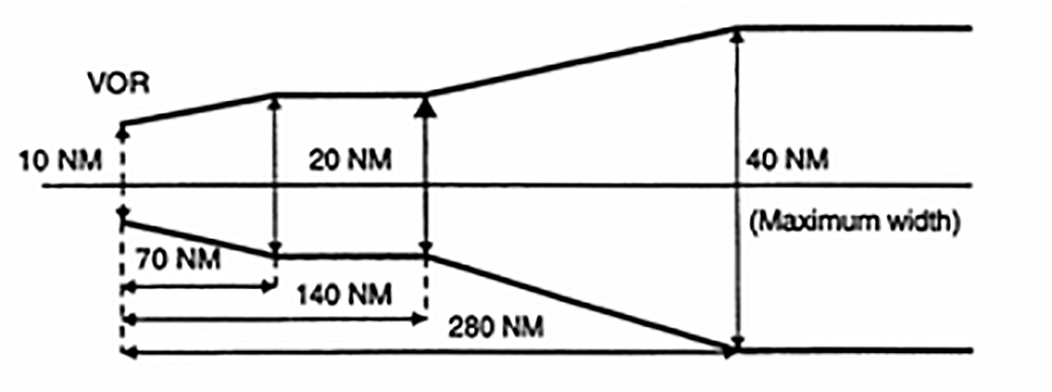
(iii)From a VOR station, the corridor width is defined as a borderline starting 5 NM either side of the VOR, diverging 4° from centreline until a width of 20 NM is reached at 70 NM out, thence paralleling the centreline until 140 NM out, thence again diverging 4° until a maximum width of 40 NM is reached at 280 NM out. Thereafter, the width remains constant (see Figure 1).
Figure 1
Corridor width from a VOR station
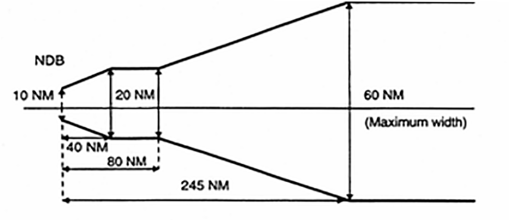
(iv)From a non-directional beacon (NDB), similarly, the corridor width is defined as a borderline starting 5 NM either side of the NDB diverging 7° until a width of 20 NM is reached 40 NM out, thence paralleling the centreline until 80 NM out, thence again diverging 7° until a maximum width of 60 NM is reached 245 NM out. Thereafter, the width remains constant (see Figure 2).
Figure 2
Corridor width from an NDB
(v)MOCA does not cover any overlapping of the corridor.
(2)Minimum off-route altitude (MORA). MORA is calculated for an area bounded by each or every second LAT/LONG square on the route facility chart (RFC)/terminal approach chart (TAC) and is based on a terrain clearance as follows:
(i)terrain with elevation up to 6 000 ft (2 000 m) – 1 000 ft above the highest terrain and obstructions;
(ii)terrain with elevation above 6 000 ft (2 000 m) – 2 000 ft above the highest terrain and obstructions.
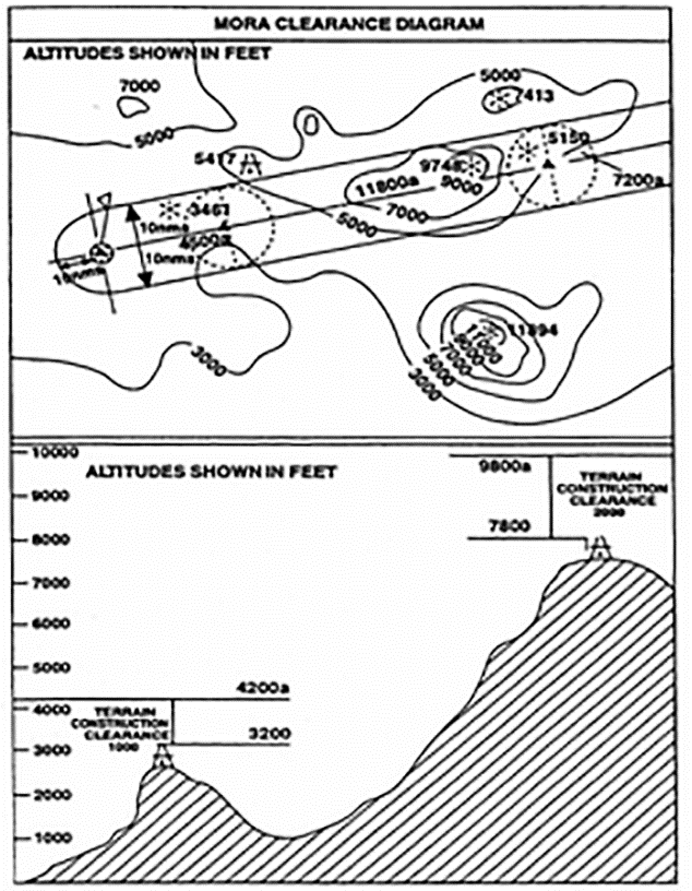
(c)Jeppesen formula (see Figure 3)
(1)MORA is a minimum flight altitude computed by Jeppesen from current operational navigation charts (ONCs) or world aeronautical charts (WACs). Two types of MORAs are charted which are:
(i)route MORAs e.g. 9800a; and
(ii)grid MORAs e.g. 98.
(2)Route MORA values are computed on the basis of an area extending 10 NM to either side of route centreline and including a 10 NM radius beyond the radio fix/reporting point or mileage break defining the route segment.
(3)MORA values clear all terrain and man-made obstacles by 1 000 ft in areas where the highest terrain elevation or obstacles are up to 5 000 ft. A clearance of 2 000 ft is provided above all terrain or obstacles that are 5 001 ft and above.
(4)A grid MORA is an altitude computed by Jeppesen and the values are shown within each grid formed by charted lines of latitude and longitude. Figures are shown in thousands and hundreds of feet (omitting the last two digits so as to avoid chart congestion). Values followed by ± are believed not to exceed the altitudes shown. The same clearance criteria as explained in (c)(3) apply.
Figure 3
Jeppesen formula
(d)ATLAS formula
(1)Minimum en-route altitude (MEA). Calculation of the MEA is based on the elevation of the highest point along the route segment concerned (extending from navigational aid to navigational aid) within a distance on either side of track as specified in Table 1 below:
Table 1
Minimum safe en-route altitude
Segment length | Distance either side of track |
Up to 100 NM | 10 NM * |
More than 100 NM | 10 % of segment length up to a maximum of 60 NM ** |
*: This distance may be reduced to 5 NM within terminal control areas (TMAs) where, due to the number and type of available navigational aids, a high degree of navigational accuracy is warranted.
**: In exceptional cases, where this calculation results in an operationally impracticable value, an additional special MEA may be calculated based on a distance of not less than 10 NM either side of track. Such special MEA will be shown together with an indication of the actual width of protected airspace.
(2)The MEA is calculated by adding an increment to the elevation specified above as appropriate, following Table 2 below. The resulting value is adjusted to the nearest 100 ft.
Table 2:
Increment added to the elevation *
Elevation of highest point | Increment |
Not above 5 000 ft | 1 500 ft |
Above 5 000 ft but not above 10 000 ft | 2 000 ft |
Above 10 000 ft | 10 % of elevation plus 1 000 ft |
*: For the last route segment ending over the initial approach fix, a reduction to 1 000 ft is permissible within TMAs where, due to the number and type of available navigation aids, a high degree of navigational accuracy is warranted.
(3)Minimum safe grid altitude (MGA). Calculation of the MGA is based on the elevation of the highest point within the respective grid area.
The MGA is calculated by adding an increment to the elevation specified above as appropriate, following Table 3 below. The resulting value is adjusted to the nearest 100 ft.
Table 3
Minimum safe grid altitude
Elevation of highest point | Increment |
Not above 5 000 ft | 1 500 ft |
Above 5 000 ft but not above 10 000 ft | 2 000 ft |
Above 10 000 ft | 10 % of elevation plus 1 000 ft |
(e)Lido formula
(1)Minimum terrain clearance altitude (MTCA)
The MTCA represents an altitude providing terrain and obstacle clearance for all airways/ATS routes, all standard terminal arrival route (STAR) segments up to IAF or equivalent end point and for selected standard instrument departures (SIDs).
The MTCA is calculated by Lido and covers terrain and obstacle clearance relevant for air navigation with the following buffers:
(i)Horizontal:
(A)for SID and STAR procedures 5 NM either side of centre line; and
(B)for airways/ATS routes 10 NM either side of centre line.
(ii)Vertical:
(A)1 000 ft up to 6 000 ft; and
(B)2 000 ft above 6 000 ft.
MTCAs are always shown in feet. The lowest indicated MTCA is 3 100 ft.
(2)Minimum grid altitude (MGA)
MGA represents the lowest safe altitude which can be flown off-track. The MGA is calculated by rounding up the elevation of the highest obstruction within the respective grid area to the next 100 ft and adding an increment of
(i)1 000 ft for terrain or obstructions up to 6 000 ft; and
(ii)2 000 ft for terrain or obstructions above 6 000 ft.
MGA is shown in hundreds of feet. The lowest indicated MGA is 2 000 ft. This value is also provided for terrain and obstacles that would result in an MGA below 2 000 ft. An exception is over water areas where the MGA can be omitted.
CAT.OP.MPA.150
Regulation (EU) 2021/1296
INTENTIONALLY LEFT BLANK
CAT.OP.MPA.155 Carriage of special categories of passengers (SCPs)
Regulation (EU) No 965/2012
(a)Persons requiring special conditions, assistance and/or devices when carried on a flight shall be considered as SCPs including at least:
(1)persons with reduced mobility (PRMs) who, without prejudice to Regulation (EC) No 1107/2006, are understood to be any person whose mobility is reduced due to any physical disability, sensory or locomotory, permanent or temporary, intellectual disability or impairment, any other cause of disability, or age;
(2)infants and unaccompanied children; and
(3)deportees, inadmissible passengers or prisoners in custody.
(b)SCPs shall be carried under conditions that ensure the safety of the aircraft and its occupants according to procedures established by the operator.
(c)SCPs shall not be allocated, nor occupy, seats that permit direct access to emergency exits or where their presence could:
(1)impede crew members in their duties;
(2)obstruct access to emergency equipment; or
(3)impede the emergency evacuation of the aircraft.
(d)The commander shall be notified in advance when SCPs are to be carried on board.
AMC1 CAT.OP.MPA.155(b) Carriage of special categories of passengers (SCPs)
ED Decision 2016/004/R
PROCEDURES
When establishing the procedures for the carriage of SCPs, the operator should take into account the following factors:
(a)the aircraft type and cabin configuration;
(b)the total number of passengers carried on board;
(c)the number and categories of SCPs, which should not exceed the number of passengers capable of assisting them in case of an emergency; and
(d)any other factor(s) or circumstances possibly impacting on the application of emergency procedures by the operating crew members.
AMC2 CAT.OP.MPA.155(b) Carriage of Special Categories of Passengers (SCPs)
ED Decision 2016/004/R
PROCEDURES TO PROVIDE INFORMATION TO SCP
The operator procedures on information provided to the SCP should specify the timing and methods on how and when the information can be provided.
AMC3 CAT.OP.MPA.155(b) Carriage of Special Categories of Passengers (SCPs)
ED Decision 2016/004/R
CONDITIONS OF SAFE CARRIAGE FOR UNACCOMPANIED CHILDREN
(a)When carrying an unaccompanied child that is not self-reliant, the operator should assess the safety risks to ensure that the child is assisted in case of an emergency situation.
(b)A child under the age of 12 years, separated from the accompanying adult, who is travelling in another cabin class, should be considered as an unaccompanied child in order to ensure that the child is assisted in case of an emergency situation.
GM1 CAT.OP.MPA.155(b) Carriage of Special Categories of Passengers (SCPs)
ED Decision 2016/004/R
PROCEDURES TO PROVIDE INFORMATION TO SCP
Providing information only at the time of booking might not be sufficient to ensure that the SCP is aware of the information at the time of the flight.
GM2 CAT.OP.MPA.155(b) Carriage of special categories of passengers (SCPs)
ED Decision 2019/019/R
INFORMATION PROVIDED TO SCPs
When establishing procedures on the information to be provided to an SCP, the operator should consider informing the SCP that cabin crew can only assist the SCP once the cabin has been evacuated. The following table contains additional information by SCP category:
SCP category | Type of information |
Unaccompanied child | Inform the unaccompanied child on the following: (a)which adult will assist with the operation of the seat belt and the fitting of the oxygen mask if the situation requires it; (b)the content of the passenger safety briefing card; and (c)in case of evacuation, to seek the assistance of adult passenger(s) in contacting a crew member. Inform the passenger sitting next to the unaccompanied child to assist with: (a)providing the child with an oxygen mask in case of decompression after fitting one’s own mask; (b)securing/releasing the child’s seat belt, if necessary; and (c)calling a cabin crew member in all other in-flight situations. When a child and the accompanying adult travel in a different class of cabin, information should be provided to the child and adult that, in the event of an emergency, they should follow the instructions of the cabin crew and not try to reunite inside the cabin as this would slow down the overall evacuation. |
Adult travelling with an infant | Information on brace position for adult with lap-held infant. Information on the use of the loop belt, in case of a lap-held infant. Information to fit own oxygen mask before fitting the infant’s oxygen mask. Information on how to evacuate when carrying an infant: (a)On land, see EASA SIB 2013-06 on evacuation of infants on aircraft equipped with inflatable slides or hatch-type overwing exits; and (b)In case of ditching, how to fit and when to inflate infant flotation aid (e.g. life jacket, flotation device). |
Physically disabled passenger (aided walking) | Inform the SCP to leave mobility aid behind in an emergency evacuation. |
Passenger with disability of upper limbs | Inform the accompanying passenger to: (a)fit the life jacket on the SCP, in case of a ditching evacuation; (b)first put on their own oxygen mask before fitting the SCP’s oxygen mask, in case of decompression; and (c)secure/release the SCP’s seat belt, if necessary. |
Passenger with disability of lower limbs | Inform the SCP: (a)on the location of the nearest suitable exit; and (b)that mobility aids might not be accessible in an emergency evacuation. |
Passenger with disability of both upper and lower limbs | Inform accompanying passenger to secure/release the SCP’s seat belt. Inform the SCP: (a)in case of an evacuation, on the location of the nearest suitable exit; (b)in case of a ditching evacuation, that the accompanying passenger should fit the life jacket on the SCP; and (c)in case of a decompression, that the accompanying passenger should first put on his/her own oxygen mask before fitting the SCP’s oxygen mask. |
Visually impaired passenger | Depending on the level of impairment, inform the visually impaired passenger on the following: (a)seat and seat belt operation; (b)location of the nearest exit (e.g. number of seat rows to the nearest exit); (c)oxygen mask deployment; (d)location of life jacket; (e)brace position; and (f)location of cabin crew call button. If available, take the aircraft demonstration equipment to the passenger for tactile assistance. |
Passenger travelling with a recognised assistance dog in the cabin | Advise how to evacuate guide dog by holding the dog and sliding. |
Stretcher occupant | Inform the stretcher occupant and the accompanying passenger that in case of an evacuation: (a)the stretcher occupant should be evacuated when the cabin area surrounding the stretcher is clear; (b)to evacuate the stretcher occupant without the stretcher, if possible; (c)to be seated when sliding, holding the stretcher occupant in front; and (d)in the event of a ditching evacuation, to fit the life jacket on the stretcher occupant. |
GM3 CAT.OP.MPA.155(b) Carriage of Special Categories of Passengers (SCPs)
ED Decision 2016/004/R
PROCEDURES
A passenger capable of assisting in case of an emergency means a passenger who is not an SCP and has no other role or private responsibility that would prevent him/her from assisting the SCP. For example, an adult travelling alone has no other role or private responsibility, unlike a family travelling together with younger children.
GM4 CAT.OP.MPA.155(b) Carriage of Special Categories of Passengers (SCPs)
ED Decision 2016/004/R
BRIEFING PROCEDURE IN A PLANNED EMERGENCY
In a planned emergency, if time permits, passengers identified by the cabin crew as capable of assisting an SCP should be briefed on the assistance they can provide.
AMC1 CAT.OP.MPA.155(c) Carriage of Special Categories of Passengers (SCPs)
ED Decision 2016/004/R
SEATING PROCEDURES
When establishing SCP seating procedures, the operator should take into account the following factors:
(a)If the SCP travels with an accompanying passenger, the accompanying passenger should be seated next to the SCP.
(b)If the SCP is unable to negotiate stairs within the cabin unaided, he/she should not be seated on the upper deck of a multi-deck aircraft if the exits are not certified for emergency evacuation on both land and water.
AMC2 CAT.OP.MPA.155(c) Carriage of Special Categories of Passengers (SCPs)
ED Decision 2016/004/R
SEATING ALLOCATION OF SCP WITH A DISABILITY AND/OR RESTRAINT AID
(a)A disability and/or restraint aid that requires to be secured around the back of the seat should not be used if there is a person seated behind unless the seating configuration is approved for the use of such devices. This is to avoid the changed dynamic seat reactions with the disability and/or restraint aid, which may lead to head injury of the passenger seated behind.
(b)If the seat design or installation would prevent head contact of the person seated behind, then no further consideration is necessary.
GM1 CAT.OP.MPA.155(c) Carriage of Special categories of Passengers (SCPs)
ED Decision 2016/004/R
GROUP SEATING
(a)Taking into account access to exits, groups of non-ambulatory SCPs should be seated throughout the cabin to ensure that each SCP is surrounded by the maximum number of passengers capable of assisting in case of an emergency.
(b)If non-ambulatory SCPs cannot be evenly distributed throughout the cabin, the operator should establish procedures to mitigate the increased safety risk such as seating of passengers capable of assisting in case of an emergency in the vicinity, additional information or training of cabin crew.
(c)A group of passengers whose physical size would possibly prevent them from moving quickly or reaching and passing through an emergency exit, should not occupy the same seat row segment to avoid overloading the structure of the seat.
GM2 CAT.OP.MPA.155(c) Carriage of Special Categories of Passengers (SCPs)
ED Decision 2016/004/R
SEATING ALLOCATION
When establishing the procedure on seating of an SCP, seats should be allocated taking into account the following:
SCP category | Seating allocation procedure |
Unaccompanied child | The seating allocation of an unaccompanied child should allow for visual or audible communication during all phases of the flight with cabin crew. Groups of unaccompanied children should be seated in mix of ages, with the tallest child seated to allow assistance with fitting drop-down oxygen mask to smaller children in case of a decompression. Where possible, one adult should occupy the seat across the aisle next to each row of unaccompanied children. |
Passenger travelling with a child of less than 12 years of age | If a child travels with an accompanying adult in the same class of cabin, the child should be seated in the same seat row segment as the accompanying adult. Where this is not possible, the child should be seated no more than one seat row or aisle away. |
Passenger whose physical size would possibly prevent him/her from passing through an emergency exit | A passenger whose physical size would possibly prevent him/her from passing through an emergency exit (e.g. Type III or Type IV exit), should be seated in the vicinity of a suitable exit, taking into account the size of the exit. Seating of more than one of such passengers in the same seat row segment should be avoided. |
Passenger with physical disability of the upper limbs | A passenger with a physical disability of the upper limbs travelling without an accompanying passenger should be allocated seats during all phases of the flight so that visual and audible communication can be established with the cabin crew. |
Passenger with disability of lower limbs | A passenger with a disability of the lower limbs should be seated in a location providing easy access to floor level exits. |
Passenger with disability of both upper and lower limbs | A passenger with a disability of both upper and lower limbs should be seated in a location providing easy access to floor level exits. |
Mentally impaired passenger | A mentally impaired passenger, who travels without an accompanying passenger, should be allocated seats during all phases of the flight so that visual and audible communication can be established with the cabin crew. |
Passenger travelling with recognised assistance dog in the cabin | Suitable arrangements should be made between the passenger and the operator in advance of a flight where a recognised assistance dog is to be accommodated. A suitable restraint harness should be provided by the owner to secure and restrain the dog during taxi, take-off, landing and turbulence. In cruise, it is acceptable for the dog to be subject to less restraint. |
Stretcher occupant | Where possible, the stretcher should be installed behind a cabin monument. Alternatively, the stretcher could be installed where it can demonstrate compliance with the appropriate certification basis (CS.25.561 and CS.25.562(b), (c)(7), (8)). Stretcher installation should be as close to the floor level non-overwing exits as practical; preferably close to a required cabin crew station with an adjacent seat for the designated accompanying passenger. |
CAT.OP.MPA.160 Stowage of baggage and cargo
Regulation (EU) No 965/2012
The operator shall establish procedures to ensure that:
(a)only hand baggage that can be adequately and securely stowed is taken into the passenger compartment; and
(b)all baggage and cargo on board that might cause injury or damage, or obstruct aisles and exits if displaced, is stowed so as to prevent movement.
AMC1 CAT.OP.MPA.160 Stowage of baggage and cargo
ED Decision 2014/015/R
STOWAGE PROCEDURES
Procedures established by the operator to ensure that hand baggage and cargo are adequately and securely stowed should take account of the following:
(a)each item carried in a cabin should be stowed only in a location that is capable of restraining it;
(b)weight limitations placarded on or adjacent to stowages should not be exceeded;
(c)under seat stowages should not be used unless the seat is equipped with a restraint bar and the baggage is of such size that it may adequately be restrained by this equipment;
(d)items should not be stowed in lavatories or against bulkheads that are incapable of restraining articles against movement forwards, sideways or upwards and unless the bulkheads carry a placard specifying the greatest mass that may be placed there;
(e)baggage and cargo placed in lockers should not be of such size that they prevent latched doors from being closed securely;
(f)baggage and cargo should not be placed where it can impede access to emergency equipment; and
(g)checks should be made before take-off, before landing and whenever the ‘fasten seat belts’ signs are illuminated or it is otherwise so ordered to ensure that baggage is stowed where it cannot impede evacuation from the aircraft or cause injury by falling (or other movement), as may be appropriate to the phase of flight.
AMC2 CAT.OP.MPA.160 Stowage of baggage and cargo
ED Decision 2014/015/R
CARRIAGE OF CARGO IN THE PASSENGER COMPARTMENT
The following should be observed before carrying cargo in the passenger compartment:
(a)for aeroplanes:
(1)dangerous goods should not be allowed; and
(2)a mix of passengers and live animals should only be allowed for pets weighing not more than 8 kg and guide dogs;
(b)for aeroplanes and helicopters:
(1)the mass of cargo should not exceed the structural loading limits of the floor or seats;
(2)the number/type of restraint devices and their attachment points should be capable of restraining the cargo in accordance with applicable Certification Specifications; and
(3)the location of the cargo should be such that, in the event of an emergency evacuation, it will not hinder egress nor impair the crew’s view.
CAT.OP.MPA.165 Passenger seating
Regulation (EU) No 965/2012
The operator shall establish procedures to ensure that passengers are seated where, in the event that an emergency evacuation is required, they are able to assist and not hinder evacuation of the aircraft.
AMC1 CAT.OP.MPA.165 Passenger seating
ED Decision 2017/008/R
EMERGENCY EXIT SEATING
The operator should make provisions so that:
(a)a passenger occupies a seat at least on each side in a seat row with direct access to an emergency exit (not staffed by a cabin crew member) during taxiing, take-off and landing unless this would be impracticable due to a low number of passengers or might negatively impact the mass and balance limitations.
(b)those passengers who are allocated seats that permit direct access to emergency exits appear to be reasonably fit, strong, and be able and willing to assist the rapid evacuation of the aircraft in an emergency after an appropriate briefing by the crew;
(c)in all cases, passengers who, because of their condition, might hinder other passengers during an evacuation or who might impede the crew in carrying out their duties, should not be allocated seats that permit direct access to emergency exits. If procedures cannot be reasonably implemented at the time of passenger ‘check-in’, the operator should establish an alternative procedure which ensures that the correct seat allocations will, in due course, be made.
AMC2 CAT.OP.MPA.165 Passenger seating
ED Decision 2014/015/R
ACCESS TO EMERGENCY EXITS
The following categories of passengers are among those who should not be allocated to, or directed to, seats that permit direct access to emergency exits:
(a)passengers suffering from obvious physical or mental disability to the extent that they would have difficulty in moving quickly if asked to do so;
(b)passengers who are either substantially blind or substantially deaf to the extent that they might not readily assimilate printed or verbal instructions given;
(c)passengers who because of age or sickness are so frail that they have difficulty in moving quickly;
(d)passengers who are so obese that they would have difficulty in moving quickly or reaching and passing through the adjacent emergency exit;
(e)children (whether accompanied or not) and infants;
(f)deportees, inadmissible passengers or persons in custody; and
(g)passengers with animals.
GM1 CAT.OP.MPA.165 Passenger seating
ED Decision 2014/015/R
DIRECT ACCESS
‘Direct access’ means a seat from which a passenger can proceed directly to the exit without entering an aisle or passing around an obstruction.
GM2 CAT.OP.MPA.165 Passenger seating
ED Decision 2017/008/R
EMERGENCY EXIT SEATING
When allocating a seat in a seat row with direct access to an emergency exit, the operator should consider at least the following:
(a)providing the passenger with the applicable emergency exit seating restrictions prior to boarding, or upon assigning a passenger to a seat, e.g. at the stage of booking, or check-in, or at the airport;
(b)utilising, as far as practicable, cabin crew members that are additional to the minimum required cabin crew complement, or positioning crew members, if available on board.
CAT.OP.MPA.170 Passenger briefing
Regulation (EU) 2019/1384
The operator shall ensure that passengers are:
(a)given briefings and demonstrations relating to safety in a form that facilitates the application of the procedures applicable in the event of an emergency; and
(b)provided with a safety briefing card on which picture-type instructions indicate the operation of safety and emergency equipment and emergency exits likely to be used by passengers.
AMC1 CAT.OP.MPA.170 Passenger briefing
ED Decision 2019/019/R
PASSENGER BRIEFING
Passenger briefings should contain the following:
(a)Before take-off
(1)Passengers should be briefed on the following items, if applicable:
(i)any cabin secured aspects, e.g. required position of seatbacks, tray tables, footrests, window blinds, etc. as applicable;
(ii)emergency lighting (floor proximity escape path markings, exit signs);
(iii)correct stowage of hand baggage and the importance of leaving hand baggage behind in case of evacuation;
(iv)the use and stowage of portable electronic devices, including in-flight entertainment (IFE) systems;
(v)the location and presentation of the safety briefing card, the importance of its contents and the need for passengers to review it prior to take-off; and
(vi)compliance with ordinance signs, pictograms or placards, and crew member instructions; and
(2)Passengers should receive a demonstration of the following:
(i)the use of safety belts or restraint systems, including how to fasten and unfasten the safety belts or restraint systems;
(ii)the location of emergency exits;
(iii)the location and use of oxygen equipment, if required. Passengers should also be briefed to extinguish all smoking materials when oxygen is being used; and
(iv)the location and use of life-jackets if required.
(3)Passengers occupying seats with direct access to emergency exits not staffed by cabin crew members should receive an additional briefing on the operation and use of the exit.
(b)After take-off
(1)Passengers should be reminded of the following, if applicable:
(i)use of safety belts or restraint systems including the safety benefits of having safety belts fastened when seated irrespective of seat belt sign illumination; and
(ii)caution when opening overhead compartments.
(c)Before landing
(1)Passengers should be reminded of the following, if applicable:
(i)use of safety belts or restraint systems;
(ii)any cabin secured aspects, e.g. required position of seatbacks, tray tables, footrests, window blinds, etc. as applicable;
(iii)correct stowage of hand baggage and the importance of leaving hand baggage behind in case of evacuation;
(iv)the use and stowage of portable electronic devices; and
(v)the location of the safety briefing card, the importance of its contents and its review.
(d)After landing
(1)Passengers should be reminded of the following:
(i)use of safety belts or restraint systems;
(ii)the use and stowage of portable electronic devices; and
(iii)caution when opening overhead compartments.
(e)Emergency during flight:
(1)Passengers should be instructed as appropriate to the circumstances.
(f)Smoking regulations
(1)The operator should determine the frequency of briefings or reminding passengers about the smoking regulations.
AMC1.1 CAT.OP.MPA.170 Passenger briefing
ED Decision 2014/015/R
PASSENGER BRIEFING
(a)The operator may replace the briefing/demonstration as set out in AMC1 CAT.OP.MPA.170 with a passenger training programme covering all safety and emergency procedures for a given type of aircraft.
(b)Only passengers who have been trained according to this programme and have flown on the aircraft type within the last 90 days may be carried on board without receiving a briefing/demonstration.
AMC2 CAT.OP.MPA.170 Passenger briefing
ED Decision 2014/015/R
SINGLE-PILOT OPERATIONS WITHOUT CABIN CREW
For single-pilot operations without cabin crew, the commander should provide safety briefings to passengers except during critical phases of flight and taxiing.
AMC3 CAT.OP.MPA.170 Passenger briefing
ED Decision 2019/019/R
IN-FLIGHT ENTERTAINMENT (IFE) SYSTEMS
When IFE systems are available by means of equipment that can be handled by passengers, including portable electronic devices (PEDs), provided by the operator for the purpose of IFE, appropriate information containing at least the following should be made available to passengers:
(a)instructions on how to safely operate the IFE system for personal use in normal conditions;
(b)restrictions, including stowage of retractable or loose items of equipment (e.g. screens or remote controls) during taxiing, take-off and landing, and in abnormal or emergency conditions; and
(c)the instruction to alert cabin crew members in case of IFE system malfunction in accordance with point (f)(9) of GM2 CAT.OP.MPA.170.
GM1 CAT.OP.MPA.170(a) Passenger briefing
ED Decision 2017/008/R
BRIEFING OF PASSENGERS OCCUPYING SEATS WITH DIRECT ACCESS TO EMERGENCY EXITS NOT STAFFED BY CABIN CREW MEMBERS
(a)The emergency exit briefing should contain instructions on the operation of the exit, assessment of surrounding conditions for the safe use of the exit, and recognition of emergency commands given by the crew.
(b)Cabin crew should verify that the passenger(s) is (are) able and willing to assist the crew in case of an emergency and that the passenger(s) has (have) understood the instructions.