
Filters
GM1 CAT.POL.A.430 & CAT.POL.A.435 Landing — dry runways & Landing — wet and contaminated runways
ED Decision 2021/005/R
LANDING DISTANCES AND CORRECTIVE FACTORS
The AFM provides performance data for landing distance under conditions defined in the applicable certification standards. This distance, commonly referred to as the ALD, is the distance from the position on the runway of the screen height to the point where the aeroplane comes to a full stop on a dry runway.
The determination of the ALD is based on the assumption that the landing is performed in accordance with the conditions and the procedures set out in the AFM on the basis of the applicable certification standards.
As a matter of fact, any particular landing may be different from the landing technique that is assumed in the AFM for certification purposes. The aircraft may approach the runway faster and/or higher than assumed; the aircraft may touch down further along the runway than the optimum point; the actual winds and other weather factors may be different from those assumed in the calculation of the ALD; and maximum braking may not be always achievable. For this reason, the LDA is required by CAT.POL.A.430 and CAT.POL.A.435 to be longer than the ALD.
The margins by which the LDA shall exceed the ALD on dry runways, in accordance with CAT.POL.A.430, are shown in the following Table 1.
Table 1: — Corrective factors for dry runways
Aeroplane category | Required Margin (dry runway) | Resulting factor (dry runway) |
All aeroplanes | ALD < 70 % of the LDA | LDA = at least 1.43 x ALD |
If the runway is wet and the AFM does not provide specific performance data for dispatch on wet runways, a further increase of 15 % of the landing distance on dry runways has to be applied, in accordance with CAT.POL.A.435, as shown in the following Table 2.
Table 2: Corrective factors for wet runways
Aeroplane category | Resulting factor (dry runway) |
All aeroplanes | LDA = at least 1.15 x 1.43 x ALD = 1.64 x ALD |
SECTION 2 – Helicopters
CHAPTER 1 – General requirements
CAT.POL.H.100 Applicability
Regulation (EU) No 965/2012
(a)Helicopters shall be operated in accordance with the applicable performance class requirements.
(b)Helicopters shall be operated in performance class 1:
(1)when operated to/from aerodromes or operating sites located in a congested hostile environment, except when operated to/from a public interest site (PIS) in accordance with CAT.POL.H.225; or
(2)when having an MOPSC of more than 19, except when operated to/from a helideck in performance class 2 under an approval in accordance with CAT.POL.H.305.
(c)Unless otherwise prescribed by (b), helicopters that have an MOPSC of 19 or less but more than nine shall be operated in performance class 1 or 2.
(d)Unless otherwise prescribed by (b), helicopters that have an MOPSC of nine or less shall be operated in performance class 1, 2 or 3.
CAT.POL.H.105 General
Regulation (EU) No 965/2012
(a)The mass of the helicopter:
(1)at the start of the take-off; or
(2)in the event of in-flight replanning, at the point from which the revised operational flight plan applies,
shall not be greater than the mass at which the applicable requirements of this Section can be complied with for the flight to be undertaken, taking into account expected reductions in mass as the flight proceeds and such fuel jettisoning as is provided for in the relevant requirement.
(b)The approved performance data contained in the AFM shall be used to determine compliance with the requirements of this Section, supplemented as necessary with other data as prescribed in the relevant requirement. The operator shall specify such other data in the operations manual. When applying the factors prescribed in this Section, account may be taken of any operational factors already incorporated in the AFM performance data to avoid double application of factors.
(c)When showing compliance with the requirements of this Section, account shall be taken of the following parameters:
(1)mass of the helicopter;
(2)the helicopter configuration;
(3)the environmental conditions, in particular:
(i)pressure altitude and temperature;
(ii)wind:
(A)except as provided in (C), for take-off, take-off flight path and landing requirements, accountability for wind shall be no more than 50 % of any reported steady headwind component of 5 kt or more;
(B)where take-off and landing with a tailwind component is permitted in the AFM, and in all cases for the take-off flight path, not less than 150 % of any reported tailwind component shall be taken into account; and
(C)where precise wind measuring equipment enables accurate measurement of wind velocity over the point of take-off and landing, wind components in excess of 50 % may be established by the operator, provided that the operator demonstrates to the competent authority that the proximity to the FATO and accuracy enhancements of the wind measuring equipment provide an equivalent level of safety;
(4)the operating techniques; and
(5)the operation of any systems that have an adverse effect on performance.
GM1 CAT.POL.H.105(c)(3)(ii)(A) General
ED Decision 2014/015/R
REPORTED HEADWIND COMPONENT
The reported headwind component should be interpreted as being that reported at the time of flight planning and may be used, provided there is no significant change of unfactored wind prior to take-off.
CAT.POL.H.110 Obstacle accountability
Regulation (EU) No 965/2012
(a)For the purpose of obstacle clearance requirements, an obstacle located beyond the FATO, in the take-off flight path, or the missed approach flight path shall be considered if its lateral distance from the nearest point on the surface below the intended flight path is not further than the following:
(1)For operations under VFR:
(i)half of the minimum width defined in the AFM — or, when no width is defined, ‘0,75 × D’, where D is the largest dimension of the helicopter when the rotors are turning;
(ii)plus, the greater of ‘0,25 × D’ or ‘3 m’;
(iii)plus:
(A)0,10 × distance DR for operations under VFR by day; or
(B)0,15 × distance DR for operations under VFR at night.
(2)For operations under IFR:
(i)‘1,5 D’ or 30 m, whichever is greater, plus:
(A)0,10 × distance DR, for operations under IFR with accurate course guidance;
(B)0,15 × distance DR, for operations under IFR with standard course guidance; or
(C)0,30 × distance DR for operations under IFR without course guidance.
(ii)When considering the missed approach flight path, the divergence of the obstacle accountability area only applies after the end of the take-off distance available.
(3)For operations with initial take-off conducted visually and converted to IFR/IMC at a transition point, the criteria required in (1) apply up to the transition point, and the criteria required in (2) apply after the transition point. The transition point cannot be located before the end of the take-off distance required for helicopters (TODRH) operating in performance class 1 or before the defined point after take-off (DPATO) for helicopters operating in performance class 2.
(b)For take-off using a back-up or a lateral transition procedure, for the purpose of obstacle clearance requirements, an obstacle located in the back-up or lateral transition area shall be considered if its lateral distance from the nearest point on the surface below the intended flight path is not further than:
(1)half of the minimum width defined in the AFM or, when no width is defined, ‘0,75 × D’;
(2)plus the greater of ‘0,25 × D’ or ‘3 m’;
(3)plus:
(i)for operations under VFR by day 0,10 × the distance travelled from the back of the FATO, or
(ii)for operations under VFR at night 0,15 × the distance travelled from the back of the FATO.
(c)Obstacles may be disregarded if they are situated beyond:
(1)7 × rotor radius (R) for day operations, if it is assured that navigational accuracy can be achieved by reference to suitable visual cues during the climb;
(2)10 × R for night operations, if it is assured that navigational accuracy can be achieved by reference to suitable visual cues during the climb;
(3)300 m if navigational accuracy can be achieved by appropriate navigation aids; or
(4)900 m in all other cases.
GM1 CAT.POL.H.110(a)(2)(i) Obstacle accountability
ED Decision 2014/015/R
COURSE GUIDANCE
Standard course guidance includes automatic direction finder (ADF) and VHF omnidirectional radio range (VOR) guidance.
Accurate course guidance includes ILS, MLS or other course guidance providing an equivalent navigational accuracy.
CHAPTER 2 – Performance class 1
CAT.POL.H.200 General
Regulation (EU) No 965/2012
Helicopters operated in performance class 1 shall be certified in category A or equivalent as determined by the Agency.
GM1 CAT.POL.H.200 & CAT.POL.H.300 & CAT.POL.H.400 General
ED Decision 2014/015/R
CATEGORY A AND CATEGORY B
(a)Helicopters that have been certified according to any of the following standards are considered to satisfy the Category A criteria. Provided that they have the necessary performance information scheduled in the AFM, such helicopters are, therefore, eligible for performance class 1 or 2 operations:
(1)certification as Category A under CS-27 or CS-29;
(2)certification as Category A under JAR-27 or JAR-29;
(3)certification as Category A under FAR Part 29;
(4)certification as group A under BCAR Section G; and
(5)certification as group A under BCAR-29.
(b)In addition to the above, certain helicopters have been certified under FAR Part 27 and with compliance with FAR Part 29 engine isolation requirements as specified in FAA Advisory Circular AC 27-1. Provided that compliance is established with the following additional requirements of CS-29:
(1)CS 29.1027(a) Independence of engine and rotor drive system lubrication;
(2)CS 29.1187(e);
(3)CS 29.1195(a) & (b) Provision of a one-shot fire extinguishing system for each engine;
(i)The requirement to fit a fire extinguishing system may be waived if the helicopter manufacturer can demonstrate equivalent safety, based on service experience for the entire fleet showing that the actual incidence of fires in the engine fire zones has been negligible.
(4)CS 29.1197;
(5)CS 29.1199;
(6)CS 29.1201; and
(7)CS 29.1323(c)(1) Ability of the airspeed indicator to consistently identify the take-off decision point,
these helicopters are considered to satisfy the requirement to be certified as equivalent to Category A.
(c)The performance operating rules of JAR-OPS 3, which were transposed into this Part, were drafted in conjunction with the performance requirements of JAR-29 Issue 1 and FAR Part 29 at amendment 29-39. For helicopters certificated under FAR Part 29 at an earlier amendment, or under BCAR section G or BCAR-29, performance data will have been scheduled in the AFM according to these earlier requirements. This earlier scheduled data may not be fully compatible with this Part.
(d)Before any AOC is issued under which performance class 1 or 2 operations are conducted, it should be established that scheduled performance data are available that are compatible with the requirements of performance class 1 and 2 respectively.
(e)Any properly certified helicopter is considered to satisfy the Category B criteria. If appropriately equipped (in accordance with CAT.IDE.H), such helicopters are, therefore, eligible for performance class 3 operations.
CAT.POL.H.205 Take-off
Regulation (EU) No 965/2012
(a)The take-off mass shall not exceed the maximum take-off mass specified in the AFM for the procedure to be used.
(b)The take-off mass shall be such that:
(1)it is possible to reject the take-off and land on the FATO in case of the critical engine failure being recognised at or before the take-off decision point (TDP);
(2)the rejected take-off distance required (RTODRH) does not exceed the rejected take-off distance available (RTODAH); and
(3)the TODRH does not exceed the take-off distance available (TODAH).
(4)Notwithstanding (b)(3), the TODRH may exceed the TODAH if the helicopter, with the critical engine failure recognised at TDP can, when continuing the take-off, clear all obstacles to the end of the TODRH by a vertical margin of not less than 10,7 m (35 ft).
(c)When showing compliance with (a) and (b), account shall be taken of the appropriate parameters of CAT.POL.H.105(c) at the aerodrome or operating site of departure.
(d)That part of the take-off up to and including TDP shall be conducted in sight of the surface such that a rejected take-off can be carried out.
(e)For take-off using a backup or lateral transition procedure, with the critical engine failure recognition at or before the TDP, all obstacles in the back-up or lateral transition area shall be cleared by an adequate margin.
AMC1 CAT.POL.H.205(b)(4) Take-off
ED Decision 2014/015/R
THE APPLICATION OF TODRH
The selected height should be determined with the use of AFM data, and be at least 10.7 m (35 ft) above:
(a)the take-off surface; or
(b)as an alternative, a level height defined by the highest obstacle in the take-off distance required.
GM1 CAT.POL.H.205(b)(4) Take-off
ED Decision 2014/015/R
THE APPLICATION OF TODRH
(a)Introduction
Original definitions for helicopter performance were derived from aeroplanes; hence, the definition of take-off distance owes much to operations from runways. Helicopters on the other hand can operate from runways, confined and restricted areas and rooftop FATOs — all bounded by obstacles. As an analogy, this is equivalent to a take-off from a runway with obstacles on and surrounding it.
It can, therefore, be said that unless the original definitions from aeroplanes are tailored for helicopters, the flexibility of the helicopter might be constrained by the language of operational performance.
This GM concentrates on the critical term ‘take-off distance required (TODRH)’ and describes the methods to achieve compliance with it and, in particular, the alternative procedure described in ICAO Annex 6 Attachment A 4.1.1.3:
(1)the take-off distance required does not exceed the take-off distance available; or
(2)as an alternative, the take-off distance required may be disregarded provided that the helicopter with the critical engine failure recognised at TDP can, when continuing the take-off, clear all obstacles between the end of the take-off distance available and the point at which it becomes established in a climb at VTOSS by a vertical margin of 10.7 m (35 ft) or more. An obstacle is considered to be in the path of the helicopter if its distance from the nearest point on the surface below the intended line of flight does not exceed 30 m or 1.5 times the maximum dimension of the helicopter, whichever is greater.
(b)Definition of TODRH
The definition of TODRH from Annex I is as follows:
‘Take-off distance required (TODRH)’ in the case of helicopters means the horizontal distance required from the start of the take-off to the point at which take-off safety speed (VTOSS), a selected height and a positive climb gradient are achieved, following failure of the critical engine being recognised at the TDP, the remaining engines operating within approved operating limits.
AMC1 CAT.POL.H.205(b)(4) states how the specified height should be determined.
The original definition of TODRH was based only on the first part of this definition.
(c)The clear area procedure (runway)
In the past, helicopters certified in Category A would have had, at the least, a ‘clear area’ procedure. This procedure is analogous to an aeroplane Category A procedure and assumes a runway (either metalled or grass) with a smooth surface suitable for an aeroplane take-off (see Figure 1).
The helicopter is assumed to accelerate down the FATO (runway) outside of the height velocity (HV) diagram. If the helicopter has an engine failure before TDP, it must be able to land back on the FATO (runway) without damage to helicopter or passengers; if there is a failure at or after TDP the aircraft is permitted to lose height — providing it does not descend below a specified height above the surface (usually 15 ft if the TDP is above 15 ft). Errors by the pilot are taken into consideration, but the smooth surface of the FATO limits serious damage if the error margin is eroded (e.g. by a change of wind conditions).
Figure 1
Clear Area take – off
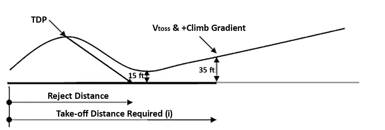
The operator only has to establish that the distances required are within the distance available (take-off distance and reject distance). The original definition of TODRH meets this case exactly.
From the end of the TODRH obstacle clearance is given by the climb gradient of the first or second climb segment meeting the requirement of CAT.POL.H.210 (or for performance class 2 (PC2): CAT.POL.H.315). The clearance margin from obstacles in the take-off flight path takes account of the distance travelled from the end of the take-off distance required and operational conditions (IMC or VMC).
(d)Category A procedures other-than-clear area
Procedures other-than-the-clear area are treated somewhat differently. However, the short field procedure is somewhat of a hybrid as either (a) or (b) of AMC1 CAT.POL.H.205(b)(4) can be utilised (the term ‘helipad’ is used in the following section to illustrate the principle only, it is not intended as a replacement for ‘aerodrome’ or ‘FATO’).
(1)Limited area, restricted area and helipad procedures (other than elevated)
The exact names of the procedure used for other-than-clear area are as many as there are manufacturers. However, principles for obstacle clearance are generic and the name is unimportant.
These procedures (see Figure 2 and Figure 3) are usually associated with an obstacle in the continued take-off area — usually shown as a line of trees or some other natural obstacle. As clearance above such obstacles is not readily associated with an accelerative procedure, as described in (c), a procedure using a vertical climb (or a steep climb in the forward, sideways or rearward direction) is utilised.
Figure 2
Short Field take-off
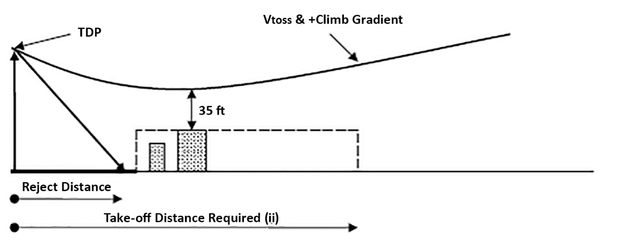
With the added complication of a TDP principally defined by height together with obstacles in the continued take off area, a drop down to within 15 ft of the take-off surface is not deemed appropriate and the required obstacle clearance is set to 35 ft (usually called ‘min-dip’). The distance to the obstacle does not need to be calculated (provided it is outside the rejected distance required), as clearance above all obstacles is provided by ensuring that helicopter does not descend below the min-dip associated with a level defined by the highest obstacle in the continued take-off area.
Figure 3
Helipad take-off
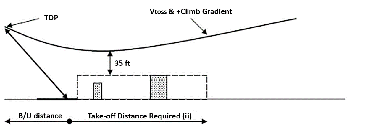
These procedures depend upon (b) of AMC1 CAT.POL.H.205(b)(4).
As shown in Figure 3, the point at which VTOSS and a positive rate of climb are met defines the TODRH. Obstacle clearance from that point is assured by meeting the requirement of CAT.POL.H.210 (or for PC2, CAT.POL.H.315). Also shown in Figure 3 is the distance behind the helipad which is the backup distance (B/U distance).
(2)Elevated helipad procedures
The elevated helipad procedure (see Figure 4) is a special case of the ground level helipad procedure discussed above.
Figure 4
Elevate Helipad take-off
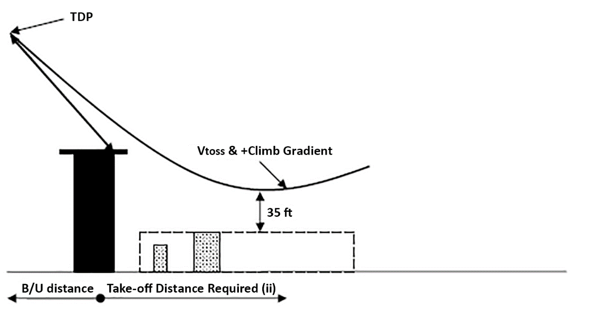
The main difference is that drop down below the level of the take-off surface is permitted. In the drop down phase, the Category A procedure ensures deck-edge clearance but, once clear of the deck-edge, the 35 ft clearance from obstacles relies upon the calculation of drop down. Subparagraph (b) of AMC1 CAT.POL.H.205(b)(4) is applied.
Although 35 ft is used throughout the requirements, it may be inadequate at particular elevated FATOs that are subject to adverse airflow effects, turbulence, etc.
AMC1 CAT.POL.H.205(e) Take-off
ED Decision 2014/015/R
OBSTACLE CLEARANCE IN THE BACKUP AREA
(a)The requirement in CAT.POL.H.205(e) has been established in order to take into account the following factors:
(1)in the backup: the pilot has few visual cues and has to rely upon the altimeter and sight picture through the front window (if flight path guidance is not provided) to achieve an accurate rearward flight path;
(2)in the rejected take-off: the pilot has to be able to manage the descent against a varying forward speed whilst still ensuring an adequate clearance from obstacles until the helicopter gets in close proximity for landing on the FATO; and
(3)in the continued take-off; the pilot has to be able to accelerate to VTOSS (take-off safety speed for Category A helicopters) whilst ensuring an adequate clearance from obstacles.
(b)The requirements of CAT.POL.H.205(e) may be achieved by establishing that:
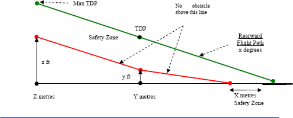
(1)in the backup area no obstacles are located within the safety zone below the rearward flight path when described in the AFM (see Figure 1, in the absence of such data in the AFM, the operator should contact the manufacturer in order to define a safety zone);or
(2)during the backup, the rejected take-off and the continued take-off manoeuvres, obstacle clearance is demonstrated to the competent authority.
Figure 1
Rearward flight path
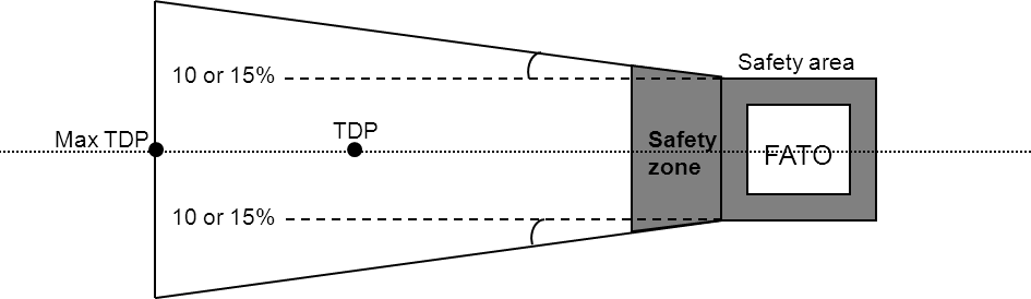
(c)An obstacle, in the backup area, is considered if its lateral distance from the nearest point on the surface below the intended flight path is not further than:
(1)half of the minimum FATO (or the equivalent term used in the AFM) width defined in the AFM (or, when no width is defined 0.75 D, where D is the largest dimension of the helicopter when the rotors are turning); plus
(2)0.25 times D (or 3 m, whichever is greater); plus
(3)0.10 for VFR day, or 0.15 for VFR night, of the distance travelled from the back of the FATO (see Figure 2).
Figure 2
Obstacle accountability
AMC1 CAT.POL.H.205 & CAT.POL.H.220 Take-off and landing
ED Decision 2014/015/R
APPLICATION FOR ALTERNATIVE TAKE-OFF AND LANDING PROCEDURES
(a)A reduction in the size of the take-off surface may be applied when the operator has demonstrated to the competent authority that compliance with the requirements of CAT.POL.H.205, 210 and 220 can be assured with:
(1)a procedure based upon an appropriate Category A take-off and landing profile scheduled in the AFM;
(2)a take-off or landing mass not exceeding the mass scheduled in the AFM for a hover-out-of-ground-effect one-engine-inoperative (HOGE OEI) ensuring that:
(i)following an engine failure at or before TDP, there are adequate external references to ensure that the helicopter can be landed in a controlled manner; and
(ii)following an engine failure at or after the landing decision point (LDP), there are adequate external references to ensure that the helicopter can be landed in a controlled manner.
(b)An upwards shift of the TDP and LDP may be applied when the operator has demonstrated to the competent authority that compliance with the requirements of CAT.POL.H.205, 210 and 220 can be assured with:
(1)a procedure based upon an appropriate Category A take-off and landing profile scheduled in the AFM;
(2)a take-off or landing mass not exceeding the mass scheduled in the AFM for a HOGE OEI ensuring that:
(i)following an engine failure at or after TDP compliance with the obstacle clearance requirements of CAT.POL.H.205 (b)(4) and CAT.POL.H.210 can be met; and
(ii)following an engine failure at or before the LDP the balked landing obstacle clearance requirements of CAT.POL.H.220 (b) and CAT.POL.H.210 can be met.
(c)The Category A ground level surface area requirement may be applied at a specific elevated FATO when the operator can demonstrate to the competent authority that the usable cue environment at that aerodrome/operating site would permit such a reduction in size.
GM1 CAT.POL.H.205&CAT.POL.H.220 Take-off and landing
ED Decision 2014/015/R
APPLICATION FOR ALTERNATIVE TAKE-OFF AND LANDING PROCEDURES
The manufacturer’s Category A procedure defines profiles and scheduled data for take-off, climb, performance at minimum operating speed and landing, under specific environmental conditions and masses.
Associated with these profiles and conditions are minimum operating surfaces, take-off distances, climb performance and landing distances; these are provided (usually in graphic form) with the take-off and landing masses and the take-off decision point (TDP) and landing decision point (LDP).
The landing surface and the height of the TDP are directly related to the ability of the helicopter — following an engine failure before or at TDP — to reject onto the surface under forced landing conditions. The main considerations in establishing the minimum size of the landing surface are the scatter during flight testing of the reject manoeuvre, with the remaining engine operating within approved limits, and the required usable cue environment.
Hence, an elevated site with few visual cues — apart from the surface itself — would require a greater surface area in order that the helicopter can be accurately positioned during the reject manoeuvre within the specified area. This usually results in the stipulation of a larger surface for an elevated site than for a ground level site (where lateral cues may be present).
This could have the unfortunate side effect that a FATO that is built 3 m above the surface (and, therefore, elevated by definition) might be out of operational scope for some helicopters — even though there might be a rich visual cue environment where rejects are not problematical. The presence of elevated sites where ground level surface requirements might be more appropriate could be brought to the attention of the competent authority.
It can be seen that the size of the surface is directly related to the requirement of the helicopter to complete a rejected take-off following an engine failure. If the helicopter has sufficient power such that a failure before or at TDP will not lead to a requirement for rejected take-off, the need for large surfaces is removed; sufficient power for the purpose of this GM is considered to be the power required for hover-out-of-ground-effect one-engine-inoperative (HOGE OEI).
Following an engine failure at or after the TDP, the continued take-off path provides OEI clearance from the take-off surface and the distance to reach a point from where climb performance in the first, and subsequent segments, is assured.
If HOGE OEI performance exists at the height of the TDP, it follows that the continued take-off profile, which has been defined for a helicopter with a mass such that a rejected take-off would be required following an engine failure at or before TDP, would provide the same, or better, obstacle clearance and the same, or less, distance to reach a point where climb performance in the first, and subsequent segments, is assured.
If the TDP is shifted upwards, provided that the HOGE OEI performance is established at the revised TDP, it will not affect the shape of the continued take-off profile but should shift the min-dip upwards by the same amount that the revised TDP has been increased — with respect to the basic TDP.
Such assertions are concerned only with the vertical or the backup procedures and can be regarded as achievable under the following circumstances:
(a)when the procedure is flown, it is based upon a profile contained in the AFM — with the exception of the necessity to perform a rejected take-off;
(b)the TDP, if shifted upwards (or upwards and backward in the backup procedure) will be the height at which the HOGE OEI performance is established; and
(c)if obstacles are permitted in the backup area, they should continue to be permitted with a revised TDP.
CAT.POL.H.210 Take-off flight path
Regulation (EU) No 965/2012
(a)From the end of the TODRH with the critical engine failure recognised at the TDP:
(1)The take-off mass shall be such that the take-off flight path provides a vertical clearance, above all obstacles located in the climb path, of not less than 10,7 m (35 ft) for operations under VFR and 10,7 m (35 ft) + 0,01 × distance DR for operations under IFR. Only obstacles as specified in CAT.POL.H.110 have to be considered.
(2)Where a change of direction of more than 15° is made, adequate allowance shall be made for the effect of bank angle on the ability to comply with the obstacle clearance requirements. This turn is not to be initiated before reaching a height of 61 m (200 ft) above the take-off surface unless it is part of an approved procedure in the AFM.
(b)When showing compliance with (a), account shall be taken of the appropriate parameters of CAT.POL.H.105(c) at the aerodrome or operating site of departure.
CAT.POL.H.215 En-route – critical engine inoperative
Regulation (EU) 2023/1020
(a)The mass of the helicopter and the flight path at all points along the route, with the critical engine inoperative and the meteorological conditions expected for the flight, shall permit compliance with any of the following points:
(1)when it is intended that the flight will be conducted at any time out of sight of the surface, the mass of the helicopter permits a rate of climb of at least 50 ft/minute with the critical engine inoperative at an altitude of at least 300 m (1 000 ft), or 600 m (2 000 ft) in areas of mountainous terrain, above all relevant terrain and obstacles along the route;
(2)when it is intended that the flight will be conducted without the surface in sight, the flight path permits the helicopter to continue flight from the cruising altitude to a height of 300 m (1 000 ft) above a landing site where a landing can be made in accordance with point CAT.POL.H.220; the flight path clears vertically, by at least 300 m (1 000 ft) or 600 m (2 000 ft) in areas of mountainous terrain, all relevant terrain and obstacles along the route; Drift-down techniques may be used;
(3)when it is intended that the flight will be conducted in VMC with the surface in sight, the flight path permits the helicopter to continue flight from the cruising altitude to a height of 300 m (1 000 ft) above a landing site where a landing can be made in accordance with point CAT.POL.H.220, without flying at any time below the appropriate minimum flight altitude; Obstacles shall be considered within a distance on either side of the route as specified for the purpose of determination of the minimum flight altitude in VFR.
(b)When showing compliance with (a)(2) or (a)(3):
(1)the critical engine is assumed to fail at the most critical point along the route;
(2)account is taken of the effects of winds on the flight path;
(3)fuel jettisoning is planned to take place only to an extent consistent with reaching the aerodrome or operating site with the required fuel reserves and using a safe procedure; and
(4)fuel jettisoning is not planned below 1 000 ft above terrain.
AMC1 CAT.POL.H.215(a)(1);(a)(2) En-route – critical engine inoperative
ED Decision 2023/007/R
RELEVANT TERRAIN AND OBSTACLES IN IFR
All terrain and obstacles along the route within the following distance on either side of the intended track should be considered:
(a)9.3 km (5 NM) to be increased to 18.5 km (10 NM) if the navigational accuracy cannot be met for 95 % of the total flight time; or
(b)when flying in accordance with PBN procedures, a distance equal to or greater than the required navigation performance.
GM1 CAT.POL.H.215(a)(3) En-route – critical engine inoperative
ED Decision 2023/007/R
RELEVANT TERRAIN AND OBSTACLES IN VFR
The terrain and obstacles to be considered are within the distance on either side of the intended track that is specified in the applicable airspace requirements:
(a)for day VFR, the distances are specified in SERA.5005(f);
(b)for night VFR, the distances are specified in SERA.5005(c), or as authorised by the competent authority.
GM1 CAT.POL.H.215(b)(3) En-route — critical engine inoperative
ED Decision 2022/005/R
FUEL JETTISON
The presence of obstacles along the en route flight path may preclude compliance with point CAT.POL.H.215(a)(1) with the planned mass at the critical point along the route. In this case, fuel jettison at the most critical point may be planned, provided that the procedures of point (d) of AMC1 CAT.OP.MPA.191(b)&(c) are complied with.
CAT.POL.H.220 Landing
Regulation (EU) No 965/2012
(a)The landing mass of the helicopter at the estimated time of landing shall not exceed the maximum mass specified in the AFM for the procedure to be used.
(b)In the event of the critical engine failure being recognised at any point at or before the landing decision point (LDP), it is possible either to land and stop within the FATO, or to perform a balked landing and clear all obstacles in the flight path by a vertical margin of 10,7 m (35 ft). Only obstacles as specified in CAT.POL.H.110 have to be considered.
(c)In the event of the critical engine failure being recognised at any point at or after the LDP, it is possible to:
(1)clear all obstacles in the approach path; and
(2)land and stop within the FATO.
(d)When showing compliance with (a) to (c), account shall be taken of the appropriate parameters of CAT.POL.H.105(c) for the estimated time of landing at the destination aerodrome or operating site, or any alternate if required.
(e)That part of the landing from the LDP to touchdown shall be conducted in sight of the surface.
GM1 CAT.POL.H.205&CAT.POL.H.220 Take-off and landing
ED Decision 2014/015/R
APPLICATION FOR ALTERNATIVE TAKE-OFF AND LANDING PROCEDURES
The manufacturer’s Category A procedure defines profiles and scheduled data for take-off, climb, performance at minimum operating speed and landing, under specific environmental conditions and masses.
Associated with these profiles and conditions are minimum operating surfaces, take-off distances, climb performance and landing distances; these are provided (usually in graphic form) with the take-off and landing masses and the take-off decision point (TDP) and landing decision point (LDP).
The landing surface and the height of the TDP are directly related to the ability of the helicopter — following an engine failure before or at TDP — to reject onto the surface under forced landing conditions. The main considerations in establishing the minimum size of the landing surface are the scatter during flight testing of the reject manoeuvre, with the remaining engine operating within approved limits, and the required usable cue environment.
Hence, an elevated site with few visual cues — apart from the surface itself — would require a greater surface area in order that the helicopter can be accurately positioned during the reject manoeuvre within the specified area. This usually results in the stipulation of a larger surface for an elevated site than for a ground level site (where lateral cues may be present).
This could have the unfortunate side effect that a FATO that is built 3 m above the surface (and, therefore, elevated by definition) might be out of operational scope for some helicopters — even though there might be a rich visual cue environment where rejects are not problematical. The presence of elevated sites where ground level surface requirements might be more appropriate could be brought to the attention of the competent authority.
It can be seen that the size of the surface is directly related to the requirement of the helicopter to complete a rejected take-off following an engine failure. If the helicopter has sufficient power such that a failure before or at TDP will not lead to a requirement for rejected take-off, the need for large surfaces is removed; sufficient power for the purpose of this GM is considered to be the power required for hover-out-of-ground-effect one-engine-inoperative (HOGE OEI).
Following an engine failure at or after the TDP, the continued take-off path provides OEI clearance from the take-off surface and the distance to reach a point from where climb performance in the first, and subsequent segments, is assured.
If HOGE OEI performance exists at the height of the TDP, it follows that the continued take-off profile, which has been defined for a helicopter with a mass such that a rejected take-off would be required following an engine failure at or before TDP, would provide the same, or better, obstacle clearance and the same, or less, distance to reach a point where climb performance in the first, and subsequent segments, is assured.
If the TDP is shifted upwards, provided that the HOGE OEI performance is established at the revised TDP, it will not affect the shape of the continued take-off profile but should shift the min-dip upwards by the same amount that the revised TDP has been increased — with respect to the basic TDP.
Such assertions are concerned only with the vertical or the backup procedures and can be regarded as achievable under the following circumstances:
(a)when the procedure is flown, it is based upon a profile contained in the AFM — with the exception of the necessity to perform a rejected take-off;
(b)the TDP, if shifted upwards (or upwards and backward in the backup procedure) will be the height at which the HOGE OEI performance is established; and
(c)if obstacles are permitted in the backup area, they should continue to be permitted with a revised TDP.
CAT.POL.H.225 Helicopter operations to/from a public interest site
Regulation (EU) 2023/1020
(a)Operations to/from a public interest site (PIS) may be conducted in performance class 2, without complying with CAT.POL.H.310(b) or CAT.POL.H.325(b), provided that all of the following are complied with:
(1)the site was established as a public interest site before 1 July 2002, or the site was established as a public interest site before 28 October 2014 and a derogation from this point granted under Article 6(6) has been notified to the Commission and the Agency before 14 June 2023;
(2)the size of the PIS or obstacle environment does not permit compliance with the requirements for operation in performance class 1;
(3)the operation is conducted with a helicopter with an MOPSC of six or less;
(4)the operator complies with CAT.POL.H.305(b)(2) and (b)(3);
(5)the helicopter mass does not exceed the maximum mass specified in the AFM for a climb gradient of 8 % in still air at the appropriate take-off safety speed (VTOSS) with the critical engine inoperative and the remaining engines operating at an appropriate power rating; and
(6)the operator has obtained prior approval for the operation from the competent authority. Before such operations take place in another Member State, the operator shall obtain an endorsement from the competent authority of that State.
(b)Site-specific procedures shall be established in the operations manual to minimise the period during which there would be danger to helicopter occupants and persons on the surface in the event of an engine failure during take-off and landing.
(c)The operations manual shall contain all the following for each PIS: a diagram or annotated photograph that shows the main aspects, the dimensions, the non-conformance with the performance class 1 requirements, the main hazards and the contingency plan should an incident occur.
(d)The operator shall keep the information provided in point (c) up to date and shall notify any changes to it to the competent authority. When operations take place in another Member State, the operator shall also notify the authority of that State.
AMC1 CAT.POL.H.225 Helicopter operations to/from a public interest site
ED Decision 2023/007/R
CHANGES TO THE OBSTACLE ENVIRONMENT
If the operator becomes aware of a change to the obstacle environment at an approved public interest site, the operator should:
(a)assess the safety impact of such new obstacles on their operations;
(b)review their site-specific procedures and modify them as necessary;
(c)discontinue operations at the site if necessary;
(d)inform the competent authority of all of the above.
GM1 CAT.POL.H.225 Helicopter operations to/from a public interest site
ED Decision 2023/007/R
UNDERLYING PRINCIPLES
(a)General
The original Joint Aviation Authorities (JAA) Appendix 1 to JAR-OPS 3.005(i) was introduced in January 2002 to address problems that had been encountered by Member States at hospital sites due to the applicable performance requirements of JAR-OPS 3 Subparts G and H. These problems were enumerated in ACJ to Appendix 1 to JAR-OPS 3.005(d) paragraph 8, part of which is reproduced below.
‘8Problems with hospital sites
During implementation of JAR-OPS 3, it was established that a number of States had encountered problems with the impact of performance rules where helicopters were operated for HEMS. Although States accept that progress should be made towards operations where risks associated with a critical power unit failure are eliminated, or limited by the exposure time concept, a number of landing sites exist which do not (or never can) allow operations to performance class 1 or 2 requirements.
These sites are generally found in a congested hostile environment:
—in the grounds of hospitals; or
—on hospital buildings;
The problem of hospital sites is mainly historical and, whilst the Authority could insist that such sites not be used - or used at such a low weight that critical power unit failure performance is assured, it would seriously curtail a number of existing operations.
Even though the rule for the use of such sites in hospital grounds for HEMS operations (Appendix 1 to JAR-OPS 3.005(d) sub-paragraph (c)(2)(i)(A)) attracts alleviation until 2005, it is only partial and will still impact upon present operations.
Because such operations are performed in the public interest, it was felt that the Authority should be able to exercise its discretion so as to allow continued use of such sites provided that it is satisfied that an adequate level of safety can be maintained - notwithstanding that the site does not allow operations to performance class 1 or 2 standards. However, it is in the interest of continuing improvements in safety that the alleviation of such operations be constrained to existing sites, and for a limited period.’
As stated in this ACJ and embodied in the text of the appendix, the solution was short-term (until 31 December 2004). During the commenting period of JAA NPA 18, representations were made to the JAA that the alleviation should be extended to 2009. The review committee, in not accepting this request, had in mind that this was a short-term solution to address an immediate problem, and a permanent solution should be sought.
(b)After 1 January 2005
Although elimination of such sites would remove the problem, it is recognised that phasing out, or rebuilding existing hospital sites, is a long-term goal which may not be cost-effective, or even possible, in some Member States.
It should be noted, however, that CAT.POL.H.225(a) limits the problem by confining approvals to hospital sites established before 1 July 2002 (established in this context means either: built before that date, or brought into service before that date — this precise wording was used to avoid problems associated with a ground level aerodrome/operating site where no building would be required). Thus the problem of these sites is contained and reducing in severity. This date was set approximately 6 months after the intended implementation of the original JAR-OPS 3 appendix.
EASA adopted the JAA philosophy that, from 1st January 2005, approval would be confined to those sites where a CAT A procedure alone cannot solve the problem. The determination of whether the helicopter can or cannot be operated in accordance with performance class 1 should be established with the helicopter at a realistic payload and fuel to complete the mission. However, in order to reduce the risk at those sites, the application of the requirements contained in CAT.POL.H.225(a) should be applied.
Additionally and in order to promote understanding of the problem, the text contained in CAT.POL.H.225(c) refers to the performance class and not to ICAO Annex 14. Thus, Part C of the operations manual should reflect the non-conformance with performance class 1, as well as the site-specific procedures (approach and departure paths) to minimise the danger to third parties in the event of an incident.
The following paragraphs explain the problem and solutions.
(c)The problem associated with such sites
There is a number of problems: some of which can be solved with the use of appropriate helicopters and procedures; and others which, because of the size of the site or the obstacle environment, cannot. They consist of:
(1)the size of the surface of the site (smaller than that required by the manufacturer’s procedure);
(2)an obstacle environment that prevents the use of the manufacturer’s procedure (obstacles in the backup area); and
(3)an obstacle environment that does not allow recovery following an engine failure in the critical phase of take-off (a line of buildings requiring a demanding gradient of climb) at a realistic payload and fuel to complete the mission.
—Problems associated with (c)(1): the inability to climb and conduct a rejected landing back to the site following an engine failure before the Decision Point (DP).
—Problems associated with (c)(2): as in (c)(1)).
—Problems associated with (c)(3): climb into an obstacle following an engine failure after DP.
Problems cannot be solved in the immediate future, but can, when mitigated with the use of the latest generation of helicopters (operated at a weight that can allow useful payloads and endurance), minimise exposure to risk.
(d)Long-term solution
(1)The derogation provided for by Article 6(6) of Regulation (EU) No 965/2012, which allows Member States to approve public interest sites under their own conditions, was meant to be a temporary transitional arrangement. This transitional arrangement was only intended to allow the continuation of existing sites. For this reason, any newly approved public interest sites that have been established since 28 October 2014 will have to be phased out by 25 May 2028.
(2)No mandatory phase-out is foreseen for sites approved under a derogation from CAT.POL.H.225 that were established as public interest sites before 28 October 2014.
(3)No mandatory phase-out is foreseen for sites approved under CAT.POL.H.225 that were established as public interest sites before 1 July 2002.
(4)A public interest site should be considered to be established at the time when it was operated in the public interest for the first time.
(5)As of 25 May 2024 there should be no more approvals of public interest sites that were established after 28 October 2014, in accordance with point ARO.OPS.220(c).
(6)As of 25 May 2024 the obstacle environment at approved public interest sites should be kept under continued review in order to avoid new obstacles causing a significant safety impact, in accordance with point ARO.OPS.220(d).
Table 1
Duration of public interest site approvals
Date on which the approved PIS was established | Maximum duration of the PIS approval |
Before 28 October 2014 | Unlimited duration, provided that there is no permanent worsening of the obstacle environment. |
After 28 October 2014 | PIS approval to expire on 25 May 2028. |
(7)Since a number of hospital sites may remain approved public interest sites in the foreseeable future, it was considered important to keep minimum performance margins when operating these sites.
(i)The performance level of 8 % climb gradient in the first segment required by point CAT.POL.H.225(a)(5) reflects ICAO Annex 14 Volume II in ‘Table 4-1 ‘Dimensions and slopes of obstacle limitations surfaces’.
This was established as a means of mitigating performance issues. It defines a proportionate mass penalty at such sites, thereby applying an additional performance margin to such operations in the interest of safety.
(ii)The performance delta is achieved without the provision of further manufacturer’s data by using existing graphs to provide the reduced take-off mass (RTOM).
(iii)If the solution in relation to the original problem is examined, the effects can be seen.
(A)Solution with relation to (c)(1): although the problem still exists, the safest procedure is a dynamic take-off reducing the time taken to achieve Vstayup and thus allowing VFR recovery — if the failure occurs at or after Vy and 200 ft, an IFR recovery is possible.
(B)Solution with relation to (c)(2): as in (c)(1) above.
(C)Solution with relation to (c)(3): once again, this does not give a complete solution; however, the performance delta minimises the time during which a climb over the obstacle cannot be achieved.
AMC1 CAT.POL.H.225(a)(5) Helicopter operations to/from a public interest site
ED Decision 2014/015/R
HELICOPTER MASS LIMITATION
(a)The helicopter mass limitation at take-off or landing specified in CAT.POL.H.225(a)(5) should be determined using the climb performance data from 35 ft to 200 ft at VTOSS (first segment of the take-off flight path) contained in the Category A supplement of the AFM (or equivalent manufacturer data acceptable in accordance with GM1-CAT.POL.H.200 & CAT.POL.H.300 & CAT.POL.H.400).
(b)The first segment climb data to be considered is established for a climb at the take-off safety speed VTOSS, with the landing gear extended (when the landing gear is retractable), with the critical engine inoperative and the remaining engines operating at an appropriate power rating (the 2 min 30 sec or 2 min OEI power rating, depending on the helicopter type certification). The appropriate VTOSS, is the value specified in the Category A performance section of the AFM for vertical take-off and landing procedures (VTOL, helipad or equivalent manufacturer terminology).
(c)The ambient conditions at the site (pressure-altitude and temperature) should be taken into account.
(d)The data are usually provided in charts in one of the following ways:
(1)Height gain in ft over a horizontal distance of 100 ft in the first segment configuration (35 ft to 200 ft, VTOSS, 2 min 30 sec/2 min OEI power rating). This chart should be entered with a height gain of 8 ft per 100 ft horizontally travelled, resulting in a mass value for every pressure-altitude/temperature combination considered.
(2)Horizontal distance to climb from 35 ft to 200 ft in the first segment configuration (VTOSS, 2 min 30 sec/2 min OEI power rating). This chart should be entered with a horizontally distance of 628 m (2 062 ft), resulting in a mass value for every pressure-altitude/temperature combination considered.
(3)Rate of climb in the first segment configuration (35 ft to 200 ft, VTOSS, 2 min 30 sec/2 min OEI power rating). This chart can be entered with a rate of climb equal to the climb speed (VTOSS) value in knots (converted to true airspeed) multiplied by 8.1, resulting in a mass value for every pressure-altitude/temperature combination considered.
GM1 CAT.POL.H.225(a)(6) Helicopter operations to/from a public interest site
ED Decision 2014/015/R
ENDORSEMENT FROM ANOTHER STATE
(a)Application to another State
To obtain an endorsement from another State, the operator should submit to that State:
(1)the reasons that preclude compliance with the requirements for operations in performance class 1;
(2)the site-specific procedures to minimise the period during which there would be danger to helicopter occupants and person on the surface in the event of an engine failure during take-off and landing; and
(3)the extract from the operations manual to comply with CAT.POL.H.225(c).
(b)Endorsement from another State
Upon receiving the endorsement from another State, the operator should submit it together with the site-specific procedures and the reasons and justification that preclude the use of performance class 1 criteria to the competent authority issuing the AOC to obtain the approval or extend the approval to a new public interest site.
CHAPTER 3 – Performance class 2
CAT.POL.H.300 General
Regulation (EU) No 965/2012
Helicopters operated in performance class 2 shall be certified in category A or equivalent as determined by the Agency.
GM to Section 2, Chapter 3 performance class 2
ED Decision 2014/015/R
OPERATIONS IN PERFORMANCE CLASS 2
(a)Introduction
This GM describes performance class 2 as established in Part-CAT. It has been produced for the purpose of:
(1)explaining the underlying philosophy of operations in performance class 2;
(2)showing simple means of compliance; and
(3)explaining how to determine — with examples and diagrams:
(i)the take-off and landing masses;
(ii)the length of the safe forced landing area;
(iii)distances to establish obstacle clearance; and
(iv)entry point(s) into performance class 1.
It explains the derivation of performance class 2 from ICAO Annex 6 Part III and describes an alleviation that may be approved in accordance with CAT.POL.H.305 following a risk assessment.
It examines the basic requirements, discusses the limits of operation, and considers the benefits of the use of performance class 2.
It contains examples of performance class 2 in specific circumstances, and explains how these examples may be generalised to provide operators with methods of calculating landing distances and obstacle clearance.
(b)Definitions used in this GM
The definitions for the following terms, used in this GM, are contained in Annex I and its AMC:
(1)distance DR;
(2)defined point after take-off (DPATO);
(3)defined point before landing (DPBL);
(4)landing distance available (LDAH);
(5)landing distance required (LDRH);
(6)performance class 2;
(7)safe forced landing (SFL); and
(8)take-off distance available (TODAH).
The following terms, which are not defined Annex I, are used in this GM:
—VT : a target speed at which to aim at the point of minimum ground clearance (min-dip) during acceleration from TDP to VTOSS;
—V50. : a target speed and height utilised to establish an AFM distance (in compliance with the requirement of CS/JAR 29.63) from which climb out is possible; and
—Vstayup : a colloquial term used to indicate a speed at which a descent would not result following an engine failure. This speed is several knots lower than VTOSS at the equivalent take-off mass.
(c)What defines performance class 2
Performance class 2 can be considered as performance class 3 take-off or landing, and performance class 1 climb, cruise and descent. It comprises an all-engines-operating (AEO) obstacle clearance regime for the take-off or landing phases, and a OEI obstacle clearance regime for the climb, cruise, descent, approach and missed approach phases.
For the purpose of performance calculations in Part-CAT, the CS/JAR 29.67 Category A climb performance criteria is used:
—150 ft/min at 1 000 ft (at Vy);
and depending on the choice of DPATO:
—100 ft/min up to 200 ft (at VTOSS)
at the appropriate power settings.
(1)Comparison of obstacle clearance in all performance classes
Figure 1 shows the profiles of the three performance classes — superimposed on one diagram.
—Performance class 1 (PC1): from TDP, requires OEI obstacle clearance in all phases of flight; the construction of Category A procedures, provides for a flight path to the first climb segment, a level acceleration segment to Vy (which may be shown concurrent with the first segment), followed by the second climb segment from Vy at 200 ft (see Figure 1).
Figure 1
All Performance Classes (a comparison)
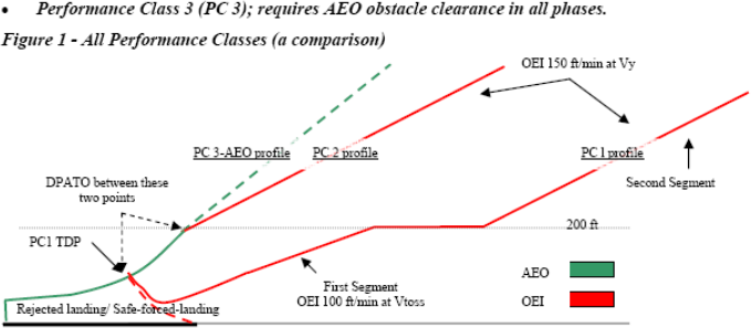
—Performance class 2 (PC2): requires AEO obstacle clearance to DPATO and OEI from then on. The take-off mass has the PC1 second segment climb performance at its basis therefore, at the point where Vy at 200 ft is reached, Performance Class 1 is achieved (see also Figure 3).
—Performance class 3 (PC3): requires AEO obstacle clearance in all phases.
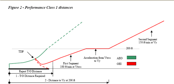
Figure 2
Performance Class 1 distances
(2)Comparison of the discontinued take-off in all performance classes
(i)PC1 — requires a prepared surface on which a rejected landing can be undertaken (no damage); and
(ii)PC2 and 3 — require a safe forced landing surface (some damage can be tolerated, but there must be a reasonable expectancy of no injuries to persons in the aircraft or third parties on the surface).
(d)The derivation of performance class 2
PC2 is primarily based on the text of ICAO Annex 6 Part III Section II and its attachments which provide for the following:
(1)obstacle clearance before DPATO: the helicopter shall be able, with all engines operating, to clear all obstacles by an adequate margin until it is in a position to comply with (2);
(2)obstacle clearance after DPATO: the helicopter shall be able, in the event of the critical engine becoming inoperative at any time after reaching DPATO, to continue the take-off clearing all obstacles along the flight path by an adequate margin until it is able to comply with en-route clearances; and
(3)engine failure before DPATO: before the DPATO, failure of the critical engine may cause the helicopter to force land; therefore, a safe forced landing should be possible (this is analogous to the requirement for a reject in performance class 1, but where some damage to the helicopter can be tolerated.)
(e)Benefits of performance class 2
Operations in performance class 2 permit advantage to be taken of an AEO procedure for a short period during take-off and landing — whilst retaining engine failure accountability in the climb, descent and cruise. The benefits include the ability to:
(1)use (the reduced) distances scheduled for the AEO — thus permitting operations to take place at smaller aerodromes and allowing airspace requirements to be reduced;
(2)operate when the safe forced landing distance available is located outside the boundary of the aerodrome;
(3)operate when the take-off distance required is located outside the boundary of the aerodrome; and
(4)use existing Category A profiles and distances when the surface conditions are not adequate for a reject, but are suitable for a safe forced landing (for example, when the ground is waterlogged).
Additionally, following a risk assessment when the use of exposure is approved by the competent authority the ability to:
(i)operate when a safe forced landing is not assured in the take-off phase; and
(ii)penetrate the HV curve for short periods during take-off or landing.
(f)Implementation of performance class 2 in Part-CAT
The following sections explain the principles of the implementation of performance class 2.
(1)Does ICAO spell it all out?
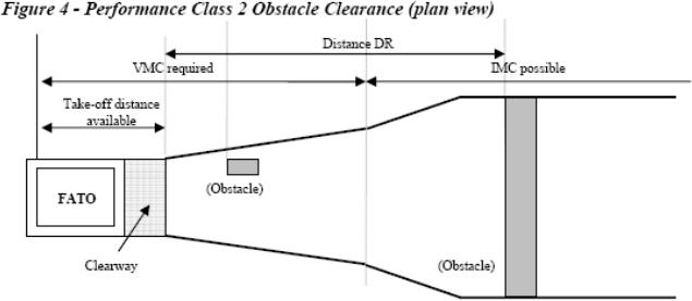
ICAO Annex 6 does not give guidance on how DPATO should be calculated nor does it require that distances be established for the take-off. However, it does require that, up to DPATO AEO, and from DPATO OEI, obstacle clearance is established (see Figure 3 and Figure 4 which are simplified versions of the diagrams contained in Annex 6 Part III, Attachment A).
(ICAO Annex 8 – Airworthiness of Aircraft (IVA 2.2.3.1.4’ and ‘IVB 2.2.7 d) requires that an AEO distance be scheduled for all helicopters operating in performance classes 2 & 3. ICAO Annex 6 is dependent upon the scheduling of the AEO distances, required in Annex 8, to provide data for the location of DPATO.)
When showing obstacle clearance, the divergent obstacle clearance height required for IFR is — as in performance class 1 — achieved by the application of the additional obstacle clearance of 0.01 distance DR (the distance from the end of ‘take-off-distance-available’ — see the pictorial representation in Figure 4 and the definition in Annex I).
As can also be seen from Figure 4, flight must be conducted in VFR until DPATO has been achieved (and deduced that if an engine failure occurs before DPATO, entry into IFR is not permitted (as the OEI climb gradient will not have been established)).
Figure 3
Performance Class 2 Obstacle Clearance
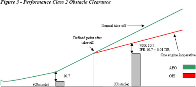
Figure 4
Performance Class 2 Obstacle Clearance (plan view)
(2)Function of DPATO
From the preceding paragraphs, it can be seen that DPATO is germane to PC2. It can also be seen that, in view of the many aspects of DPATO, it has, potentially, to satisfy a number of requirements that are not necessarily synchronised (nor need to be).
It is clear that it is only possible to establish a single point for DPATO, satisfying the requirement of (d)(2) & (d)(3), when:
—accepting the TDP of a Category A procedure; or
—extending the safe forced landing requirement beyond required distances (if data are available to permit the calculation of the distance for a safe forced landing from the DPATO).
It could be argued that the essential requirement for DPATO is contained in section (d)(2) — OEI obstacle clearance. From careful examination of the flight path reproduced in Figure 3 above, it may be reasonably deduced that DPATO is the point at which adequate climb performance is established (examination of Category A procedures would indicate that this could be (in terms of mass, speed and height above the take-off surface) the conditions at the start of the first or second segments — or any point between.)
(The diagrams in Attachment A of ICAO Annex 6 do not appear to take account of drop down — permitted under Category A procedures; similarly with helideck departures, the potential for acceleration in drop down below deck level (once the deck edge has been cleared) is also not shown. These omissions could be regarded as a simplification of the diagram, as drop down is discussed and accepted in the accompanying ICAO text.)
It may reasonably be argued that, during the take-off and before reaching an appropriate climb speed (VTOSS or Vy), Vstayup will already have been achieved (where Vstayup is the ability to continue the flight and accelerate without descent — shown in some Category A procedures as VT or target speed) and where, in the event of an engine failure, no landing would be required.
It is postulated that, to practically satisfy all the requirements of (d)(1), (2) and (3), DPATO does not need to be defined at one synchronised point; provisions can be met separately, i.e. defining the distance for a safe forced landing, and then establishing the OEI obstacle clearance flight path.
As the point at which the helicopter’s ability to continue the flight safely, with the critical engine inoperative is the critical element, it is that for which DPATO is used in this text.
Figure 5
The three elements in a PC 2 take-off
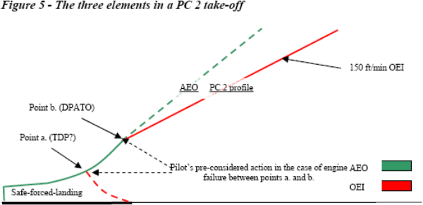
(i)The three elements from the pilot’s perspective
When seen from the pilot’s perspective (see Figure 5), there are three elements of the PC 2 take-off — each with associated related actions which need to be considered in the case of an engine failure:
(A)action in the event of an engine failure — up to the point where a forced-landing will be required;
(B)action in the event of an engine failure — from the point where OEI obstacle clearance is established (DPATO); and
(C)pre-considered action in the event of an engine failure — in the period between (A) and (B)
The action of the pilot in (A) and (B) is deterministic, i.e. it remains the same for every occasion. For pre-consideration of the action at point (C), as is likely that the planned flight path will have to be abandoned (the point at which obstacle clearance using the OEI climb gradients not yet being reached), the pilot must (before take-off) have considered his/her options and the associated risks, and have in mind the course of action that will be pursued in the event of an engine failure during that short period. (As it is likely that any action will involve turning manoeuvres, the effect of turns on performance must be considered.)
(3)Take-off mass for performance class 2
As previously stated, performance class 2 is an AEO take-off that, from DPATO, has to meet the requirement for OEI obstacle clearance in the climb and en-route phases. Take-off mass is, therefore, the mass that gives at least the minimum climb performance of 150 ft/min at Vy, at 1 000 ft above the take-off point, and obstacle clearance.
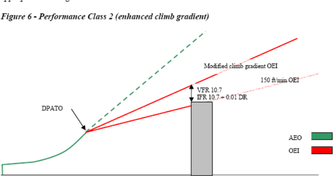
As can be seen in Figure 6 below, the take-off mass may have to be modified when it does not provide the required OEI clearance from obstacles in the take-off-flight path (exactly as in performance class 1). This could occur when taking off from an aerodrome/operating site where the flight path has to clear an obstacle such a ridge line (or line of buildings) that can neither be:
(i)flown around using VFR and see and avoid; nor
(ii)cleared using the minimum climb gradient given by the take-off mass (150 ft/min at 1 000 ft).
In this case, the take-off mass has to be modified (using data contained in the AFM) to give an appropriate climb gradient.
Figure 6
Performance Class 2 (enhanced climb gradient)
(4)Do distances have to be calculated?
Distances do not have to be calculated if, by using pilot judgement or standard practice, it can be established that:
(i)a safe forced landing is possible following an engine failure (notwithstanding that there might be obstacles in the take-off path); and
(ii)obstacles can be cleared (or avoided) — AEO in the take-off phase and OEI in the climb.
If early entry (in the sense of cloud base) into IMC is expected, an IFR departure should be planned. However, standard masses and departures can be used when described in the operations manual.
(5)The use of Category A data
In Category A procedures, TDP is the point at which either a rejected landing or a safe continuation of the flight, with OEI obstacle clearance, can be performed.
For PC2 (when using Category A data), only the safe forced landing (reject) distance depends on the equivalent of the TDP; if an engine fails between TDP and DPATO, the pilot has to decide what action is required. It is not necessary for a safe forced landing distance to be established from beyond the equivalent of TDP (see Figure 5 and discussion in (f)(2)(ii)(A)).
Category A procedures based on a fixed VTOSS are usually optimised either for the reduction of the rejected take-off distance, or the take-off distance. Category A procedures based on a variable VTOSS allow either a reduction in required distances (low VTOSS) or an improvement in OEI climb capability (high VTOSS). These optimisations may be beneficial in PC2 to satisfy the dimensions of the take-off site.
In view of the different requirements for PC2 (from PC1), it is perfectly acceptable for the two calculations (one to establish the safe forced landing distance and the other to establish DPATO) to be based upon different Category A procedures. However, if this method is used, the mass resulting from the calculation cannot be more than the mass from the more limiting of the procedures.
(6)DPATO and obstacle clearance
If it is necessary for OEI obstacle clearance to be established in the climb, the starting point (DPATO) for the (obstacle clearance) gradient has to be established. Once DPATO is defined, the OEI obstacle clearance is relatively easy to calculate with data from the AFM.
(i)DPATO based on AEO distance
In the simplest case; if provided, the scheduled AEO to 200 ft at Vy can be used (see Figure 7).
Figure 7
Suggested AEO locations for DPATO
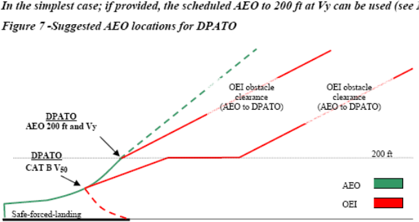
Otherwise, and if scheduled in the AFM, the AEO distance to 50 ft (V50) — determined in accordance with CS/JAR 29.63 — can be used (see Figure 7). Where this distance is used, it will be necessary to ensure that the V50 climb out speed is associated with a speed and mass for which OEI climb data are available so that, from V50, the OEI flight path can be constructed.
(ii)DPATO based on Category A distances
It is not necessary for specific AEO distances to be used (although for obvious reasons it is preferable); if they are not available, a flight path (with OEI obstacle clearance) can be established using Category A distances (see Figure 8 and Figure 9) — which will then be conservative.
Figure 8
Using Cat A data; actual and apparent position of DPATO (Vtoss and start of first segment)
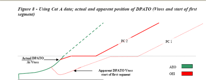
The apparent DPATO is for planning purposes only in the case where AEO data are not available to construct the take-off flight path. The actual OEI flight path will provide better obstacle clearance than the apparent one (used to demonstrate the minimum requirement) — as seen from the firm and dashed lines in the above figure.
Figure 9
Using Cat A data; actual and apparent position of DPATO (Vy and start of second segment)
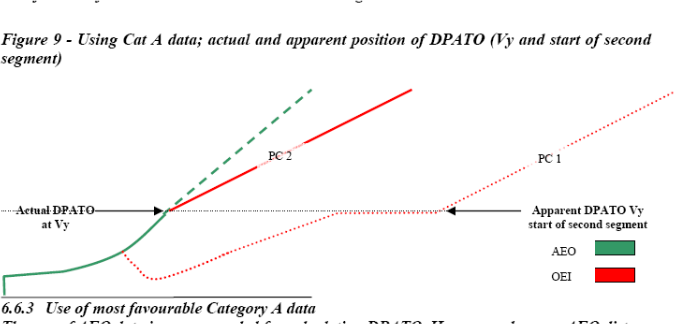
(iii)Use of most favourable Category A data
The use of AEO data are recommended for calculating DPATO. However, where an AEO distance is not provided in the flight manual, distance to Vy at 200 ft, from the most favourable of the Category A procedures, can be used to construct a flight path (provided it can be demonstrated that AEO distance to 200 ft at Vy is always closer to the take-off point than the CAT A OEI flight path).
In order to satisfy the requirement of CAT.POL.H.315, the last point from where the start of OEI obstacle clearance can be shown is at 200 ft.
(7)The calculation of DPATO — a summary
DPATO should be defined in terms of speed and height above the take-off surface and should be selected such that AFM data (or equivalent data) are available to establish the distance from the start of the take-off up to the DPATO (conservatively if necessary).
(i)First method
DPATO is selected as the AFM Category B take-off distance (V50 speed or any other take-off distance scheduled in accordance with CS/JAR 29.63) provided that within the distance the helicopter can achieve:
(A)one of the VTOSS values (or the unique VTOSS value if it is not variable) provided in the AFM, selected so as to assure a climb capability according to Category A criteria; or
(B)Vy.
Compliance with CAT.POL.H.315 would be shown from V50 (or the scheduled Category B take-off distance).
(ii)Second method
DPATO is selected as equivalent to the TDP of a Category A ‘clear area’ take-off procedure conducted in the same conditions.
Compliance with CAT.POL.H.315 would be shown from the point at which VTOSS, a height of at least 35 ft above the take-off surface and a positive climb gradient are achieved (which is the Category A ‘clear area’ take-off distance).
Safe forced landing areas should be available from the start of the take-off, to a distance equal to the Category A ‘clear area’ rejected take-off distance.
(iii)Third method
As an alternative, DPATO could be selected such that AFM OEI data are available to establish a flight path initiated with a climb at that speed. This speed should then be:
(A)one of the VTOSS values (or the unique VTOSS value if it is not variable) provided in the AFM, selected so as to assure a climb capability according to Category A criteria; or
(B)Vy
The height of the DPATO should be at least 35 ft and can be selected up to 200 ft. Compliance with CAT.POL.H.315 would be shown from the selected height.
(8)Safe forced landing distance
Except as provided in (f)(7)(ii), the establishment of the safe forced landing distance could be problematical as it is not likely that PC2 specific data will be available in the AFM.
By definition, the Category A reject distance may be used when the surface is not suitable for a reject, but may be satisfactory for a safe forced landing (for example, where the surface is flooded or is covered with vegetation).
Any Category A (or other accepted) data may be used to establish the distance. However, once established, it remains valid only if the Category A mass (or the mass from the accepted data) is used and the Category A (or accepted) AEO profile to the TDP is flown. In view of these constraints, the likeliest Category A procedures are the clear area or the short field (restricted area/site) procedures.
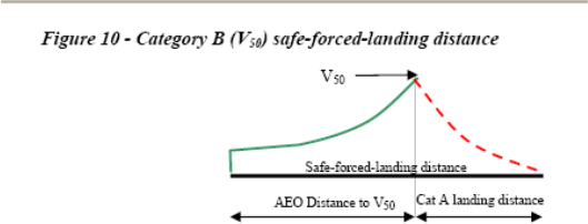
From Figure 10, it can be seen that if the Category B V50 procedure is used to establish DPATO, the combination of the distance to 50 ft and the Category A ‘clear area’ landing distance, required by CS/JAR 29.81 (the horizontal distance required to land and come to a complete stop from a point 50 ft above the landing surface), will give a good indication of the maximum safe-forced-landing distance required (see also the explanation on Vstayup above).
Figure 10
Category B (V50) safe–forced–landing distance
(9)Performance class 2 landing
For other than PC2 operations to elevated FATOs or helidecks (see section (g)(4)(i)), the principles for the landing case are much simpler. As the performance requirements for PC1 and PC2 landings are virtually identical, the condition of the landing surface is the main issue.
If the engine fails at any time during the approach, the helicopter must be able either: to perform a go-around meeting the requirements of CAT.POL.H.315; or perform a safe forced landing on the surface. In view of this, and if using PC1 data, the LDP should not be lower that the corresponding TDP (particularly in the case of a variable TDP).
The landing mass will be identical to the take-off mass for the same site (with consideration for any reduction due to obstacle clearance — as shown in Figure 6 above).
In the case of a balked landing (i.e. the landing site becomes blocked or unavailable during the approach), the full requirement for take-off obstacle clearance must be met.
(g)Operations in performance class 2 with exposure
The Implementing Rules offer an opportunity to discount the requirement for an assured safe forced landing area in the take-off or landing phase — subject to an approval from the competent authority. The following sections deals with this option:
(1)Limit of exposure
As stated above, performance class 2 has to ensure AEO obstacle clearance to DPATO and OEI obstacle clearance from that point. This does not change with the application of exposure.
It can, therefore, be stated that operations with exposure are concerned only with alleviation from the requirement for the provision of a safe forced landing.
The absolute limit of exposure is 200 ft — from which point OEI obstacle clearance must be shown.
(2)The principle of risk assessment
ICAO Annex 6 Part III Chapter 3.1.2 states that:
‘3.1.2 In conditions where the safe continuation of flight is not ensured in the event of a critical engine failure, helicopter operations shall be conducted in a manner that gives appropriate consideration for achieving a safe forced landing.’
Although a safe forced landing may no longer be the (absolute) Standard, it is considered that risk assessment is obligatory to satisfy the amended requirement for ‘appropriate consideration’.
Risk assessment used for fulfilment of this proposed Standard is consistent with principles described in ‘AS/NZS 4360:1999’. Terms used in this text and defined in the AS/NZS Standard are shown in Sentence Case e.g. risk assessment or risk reduction.
(3)The application of risk assessment to performance class 2
Under circumstances where no risk attributable to engine failure (beyond that inherent in the safe forced landing) is present, operations in performance class 2 may be conducted in accordance with the non-alleviated requirements contained above — and a safe forced landing will be possible.
Under circumstances where such risk would be present, i.e. operations to an elevated FATO (deck edge strike); or, when permitted, operations from a site where a safe forced landing cannot be accomplished because the surface is inadequate; or where there is penetration into the HV curve for a short period during take-off or landing (a limitation in CS/JAR 29 AFMs), operations have to be conducted under a specific approval.
Provided such operations are risk assessed and can be conducted to an established safety target, they may be approved in accordance with CAT.POL.H.305.
(i)The elements of the risk management
The approval process consists of an operational risk assessment and the application of four principles:
(A)a safety target;
(B)a helicopter reliability assessment;
(C)continuing airworthiness; and
(D)mitigating procedures.
(ii)The safety target
The main element of the risk assessment when exposure was initially introduced by the JAA into JAR-OPS 3 (NPA OPS-8), was the assumption that turbine engines in helicopters would have failure rates of about 1:100 000 per flying hour, which would permit (against the agreed safety target of 5 x 10⁻⁸ per event) an exposure of about 9 seconds for twins during the take-off or landing event. (When choosing this target it was assumed that the majority of current well-maintained turbine powered helicopters would be capable of meeting the event target — it, therefore, represents the residual risk).
(Residual risk is considered to be the risk that remains when all mitigating procedures — airworthiness and operational — are applied (see sections (g)(3)(iv) and (g)(3)(v))).
(iii)The reliability assessment
The reliability assessment was initiated to test the hypothesis (stated in (g)(3)(ii) ) that the majority of turbine powered types would be able to meet the safety target. This hypothesis could only be confirmed by an examination of the manufacturers’ power-loss data.
(iv)Mitigating procedures (airworthiness)
Mitigating procedures consist of a number of elements:
(A)the fulfilment of all manufacturers’ safety modifications;
(B)a comprehensive reporting system (both failures and usage data); and
(C)the implementation of a usage monitoring system (UMS).
Each of these elements is to ensure that engines, once shown to be sufficiently reliable to meet the safety target, will sustain such reliability (or improve upon it).
The monitoring system is felt to be particularly important as it had already been demonstrated that when such systems are in place it inculcates a more considered approach to operations. In addition, the elimination of ‘hot starts’, prevented by the UMS, itself minimises the incidents of turbine burst failures.
(v)Mitigating procedures (operations)
Operational and training procedures, to mitigate the risk — or minimise the consequences — are required of the operator. Such procedures are intended to minimise risk by ensuring that:
(A)the helicopter is operated within the exposed region for the minimum time; and
(B)simple but effective procedures are followed to minimise the consequence should an engine failure occur.
(4)Operation with exposure
When operating with exposure, there is alleviation from the requirement to establish a safe forced landing area (which extends to landing as well as take-off). However, the requirement for obstacle clearance — AEO in the take-off and from DPATO OEI in the climb and en-route phases — remains (both for take-off and landing).
The take-off mass is obtained from the more limiting of the following:
—the climb performance of 150 ft/min at 1 000 ft above the take-off point; or
—obstacle clearance (in accordance with (f)(3) above); or
—AEO hover out of ground effect (HOGE) performance at the appropriate power setting. (AEO HOGE is required to ensure acceleration when (near) vertical dynamic take-off techniques are being used. Additionally, for elevated FATO or helidecks, it ensures a power reserve to offset ground cushion dissipation; and ensures that, during the landing manoeuvre, a stabilised HOGE is available — should it be required.)
(i)Operations to elevated FATOs or helidecks
PC2 operations to elevated FATOs and helidecks are a specific case of operations with exposure. In these operations, the alleviation covers the possibility of:
(A)a deck-edge strike if the engine fails early in the take-off or late in the landing;
(B)penetration into the HV Curve during take-off and landing; and
(C)forced landing with obstacles on the surface (hostile water conditions) below the elevated FATO (helideck). The take-of mass is as stated above and relevant techniques are as described in GM1 CAT.POL.H.310(c) & CAT.POL.H.325(c).
It is unlikely that the DPATO will have to be calculated with operations to helidecks (due to the absence of obstacles in the take-off path).
(ii)Additional requirements for operations to helidecks in a hostile environment
For a number of reasons (e.g. the deck size, and the helideck environment — including obstacles and wind vectors), it was not anticipated that operations in PC1 would be technically feasible or economically justifiable by the projected JAA deadline of 2010 (OEI HOGE could have provided a method of compliance, but this would have resulted in a severe and unwarranted restriction on payload/range).
However, due to the severe consequences of an engine failure to helicopters involved in take-off and landings to helidecks located in hostile sea areas (such as the North Sea or the North Atlantic), a policy of risk reduction is called for. As a result, enhanced class 2 take-off and landing masses together with techniques that provide a high confidence of safety due to:
(A)deck-edge avoidance; and
(B)drop-down that provides continued flight clear of the sea,
are seen as practical measures.
For helicopters which have a Category A elevated helideck procedure, certification is satisfied by demonstrating a procedure and adjusted masses (adjusted for wind as well as temperature and pressure) that assure a 15-ft deck edge clearance on take-off and landing. It is, therefore, recommended that manufacturers, when providing enhanced PC2 procedures, use the provision of this deck-edge clearance as their benchmark.
As the height of the helideck above the sea is a variable, drop down has to be calculated; once clear of the helideck, a helicopter operating in PC1 would be expected to meet the 35-ft obstacle clearance. Under circumstances other than open sea areas and with less complex environmental conditions, this would not present difficulties. As the provision of drop down takes no account of operational circumstances, standard drop down graphs for enhanced PC2 — similar to those in existence for Category A procedures — are anticipated.
Under conditions of offshore operations, calculation of drop down is not a trivial matter — the following examples indicate some of the problems which might be encountered in hostile environments:
(A)Occasions when tide is not taken into account and the sea is running irregularly — the level of the obstacle (i.e. the sea) is indefinable making a true calculation of drop down impossible.
(B)Occasions when it would not be possible — for operational reasons — for the approach and departure paths to be clear of obstacles — the ‘standard’ calculation of drop-down could not be applied.
Under these circumstances, practicality indicates that drop down should be based upon the height of the deck AMSL and the 35-ft clearance should be applied.
There are, however, other and more complex issues which will also affect the deck-edge clearance and drop down calculations.
(C)When operating to moving decks on vessels, a recommended landing or take-off profile might not be possible because the helicopter might have to hover alongside in order that the rise and fall of the ship is mentally mapped; or, on take-off re-landing in the case of an engine failure might not be an option.
Under these circumstances, the commander might adjust the profiles to address a hazard more serious or more likely than that presented by an engine failure.
It is because of these and other (unforeseen) circumstances that a prescriptive requirement is not used. However, the target remains a 15-ft deck-edge clearance and a 35-ft obstacle clearance and data should be provided such that, where practically possible, these clearances can be planned.
As accident/incident history indicates that the main hazard is collision with obstacles on the helideck due to human error, simple and reproducible take-off and landing procedures are recommended.
In view of the reasons stated above, the future requirement for PC1 was replaced by the new requirement that the take-off mass takes into account:
—the procedure;
—deck-edge miss; and
—drop down appropriate to the height of the helideck.
This will require calculation of take-off mass from information produced by manufacturers reflecting these elements. It is expected that such information will be produced by performance modelling/simulation using a model validated through limited flight testing.
(iii)Operations to helidecks for helicopters with a maximum operational passenger seating configuration (MOPSC) of more than 19
The original requirement for operations of helicopters with an MOPSC of more than 19 was PC1 (as set out in CAT.POL.H.100(b)(2)).
However, when operating to helidecks, the problems enumerated in (g)(4)(ii) above are equally applicable to these helicopters. In view of this, but taking into account that increased numbers are (potentially) being carried, such operations are permitted in PC2 (CAT.POL.H.100(b)(2)) but, in all helideck environments (both hostile and non-hostile), have to satisfy, the additional requirements, set out in (g)(4)(ii) above.
CAT.POL.H.305 Operations without an assured safe forced landing capability
Regulation (EU) No 965/2012
(a)Operations without an assured safe forced landing capability during the take-off and landing phases shall only be conducted if the operator has been granted an approval by the competent authority.
(b)To obtain and maintain such approval the operator shall:
(1)conduct a risk assessment, specifying:
(i)the type of helicopter; and
(ii)the type of operations;
(2)implement the following set of conditions:
(i)attain and maintain the helicopter/engine modification standard defined by the manufacturer;
(ii)conduct the preventive maintenance actions recommended by the helicopter or engine manufacturer;
(iii)include take-off and landing procedures in the operations manual, where they do not already exist in the AFM;
(iv)specify training for flight crew; and
(v)provide a system for reporting to the manufacturer loss of power, engine shutdown or engine failure events;
and
(3)implement a usage monitoring system (UMS).
AMC1 CAT.POL.H.305(a) Operations without an assured safe forced landing capability
ED Decision 2016/022/R
VALIDITY OF THE RISK ASSESSMENT
The operator should periodically review and update the procedures and associated risk assessments, pertaining to the granting of the CAT.POL.H.305(a) approval, to ensure that they are adequate and remain relevant for the operation.
AMC1 CAT.POL.H.305(b) Helicopter operations without an assured safe forced landing capability
ED Decision 2014/015/R
ENGINE RELIABILITY STATISTICS
(a)As part of the risk assessment prior to granting an approval under CAT.POL.H.305, the operator should provide appropriate engine reliability statistics available for the helicopter type and the engine type.
(b)Except in the case of new engines, such data should show sudden power loss from the set of in-flight shutdown (IFSD) events not exceeding 1 per 100 000 engine hours in a 5 year moving window. However, a rate in excess of this value, but not exceeding 3 per 100 000 engine hours, may be accepted by the competent authority after an assessment showing an improving trend.
(c)New engines should be assessed on a case-by-case basis.
(d)After the initial assessment, updated statistics should be periodically reassessed; any adverse sustained trend will require an immediate evaluation to be accomplished by the operator in consultation with the competent authority and the manufacturers concerned. The evaluation may result in corrective action or operational restrictions being applied.
(e)The purpose of this paragraph is to provide guidance on how the in-service power plant sudden power loss rate is determined.
(1)Share of roles between the helicopter and engine type certificate holders (TCH)
(i)The provision of documents establishing the in-service sudden power loss rate for the helicopter/engine installation; the interface with the operational authority of the State of the operator should be the engine TCH or the helicopter TCH depending on the way they share the corresponding analysis work.
(ii)The engine TCH should provide the helicopter TCH with a document including: the list of in-service power loss events, the applicability factor for each event (if used), and the assumptions made on the efficiency of any corrective actions implemented (if used).
(iii)The engine or helicopter TCH should provide the operational authority of the State of the operator, with a document that details the calculation results taking into account the following:
(A)events caused by the engine and the events caused by the engine installation;
(B)applicability factor for each event (if used), the assumptions made on the efficiency of any corrective actions implemented on the engine and on the helicopter (if used); and
(C)calculation of the power plant power loss rate.
(2)Documentation
The following documentation should be updated every year:
(i)the document with detailed methodology and calculation as distributed to the authority of the State of design;
(ii)a summary document with results of computation as made available on request to any operational authority; and
(iii)a service letter establishing the eligibility for such operation and defining the corresponding required configuration as provided to the operators.
(3)Definition of ‘sudden in-service power loss’
Sudden in-service power loss is an engine power loss:
(i)larger than 30 % of the take-off power;
(ii)occurring during operation; and
(iii)without the occurrence of an early intelligible warning to inform and give sufficient time for the pilot to take any appropriate action.
(4)Database documentation
Each power loss event should be documented, by the engine and/or helicopter TCHs, as follows:
(i)incident report number;
(ii)engine type;
(iii)engine serial number;
(iv)helicopter serial number;
(v)date;
(vi)event type (demanded IFSD, un-demanded IFSD);
(vii)presumed cause;
(viii)applicability factor when used; and
(ix)reference and assumed efficiency of the corrective actions that will have to be applied (if any).
(5)Counting methodology
Various methodologies for counting engine power loss rate have been accepted by authorities. The following is an example of one of these methodologies.
(i)The events resulting from:
(A)unknown causes (wreckage not found or totally destroyed, undocumented or unproven statements);
(B)where the engine or the elements of the engine installation have not been investigated (for example, when the engine has not been returned by the customer); or
(C)an unsuitable or non-representative use (operation or maintenance) of the helicopter or the engine,
are not counted as engine in-service sudden power loss and the applicability factor is 0 %.
(ii)The events caused by:
(A)the engine or the engine installation; or
(B)the engine or helicopter maintenance, when the applied maintenance was compliant with the maintenance manuals,
are counted as engine in-service sudden power loss and the applicability factor is 100 %.
(iii)For the events where the engine or an element of the engine installation has been submitted for investigation, but where this investigation subsequently failed to define a presumed cause, the applicability factor is 50 %.
(6)Efficiency of corrective actions
The corrective actions made by the engine and helicopter manufacturers on the definition or maintenance of the engine or its installation may be defined as mandatory for specific operations. In this case, the associated reliability improvement may be considered as a mitigating factor for the event.
A factor defining the efficiency of the corrective action may be applied to the applicability factor of the concerned event.
(7)Method of calculation of the power plant power loss rate
The detailed method of calculation of the power plant power loss rate should be documented by engine or helicopter TCH and accepted by the relevant authority.
AMC2 CAT.POL.H.305(b) Helicopter operations without an assured safe forced landing capability
ED Decision 2014/015/R
IMPLEMENTATION OF THE SET OF CONDITIONS
To obtain an approval under CAT.POL.H.305(a), the operator conducting operations without an assured safe forced landing capability should implement the following:
(a)Attain and then maintain the helicopter/engine modification standard defined by the manufacturer that has been designated to enhance reliability during the take-off and landing phases.
(b)Conduct the preventive maintenance actions recommended by the helicopter or engine manufacturer as follows:
(1)engine oil spectrometric and debris analysis — as appropriate;
(2)engine trend monitoring, based on available power assurance checks;
(3)engine vibration analysis (plus any other vibration monitoring systems where fitted); and
(4)oil consumption monitoring.
(c)The usage monitoring system should fulfil at least the following:
(1)Recording of the following data:
(i)date and time of recording, or a reliable means of establishing these parameters;
(ii)amount of flight hours recorded during the day plus total flight time;
(iii)N1 (gas producer RPM) cycle count;
(iv)N2 (power turbine RPM) cycle count (if the engine features a free turbine);
(v)turbine temperature exceedance: value, duration;
(vi)power-shaft torque exceedance: value, duration (if a torque sensor is fitted);
(vii)engine shafts speed exceedance: value, duration.
(2)Data storage of the above parameters, if applicable, covering the maximum flight time in a day, and not less than 5 flight hours, with an appropriate sampling interval for each parameter.
(3)The system should include a comprehensive self-test function with a malfunction indicator and a detection of power-off or sensor input disconnection.
(4)A means should be available for downloading and analysis of the recorded parameters. Frequency of downloading should be sufficient to ensure data are not lost through overwriting.
(5)The analysis of parameters gathered by the usage monitoring system, the frequency of such analysis and subsequent maintenance actions should be described in the maintenance documentation.
(6)The data should be stored in an acceptable form and accessible to the competent authority for at least 24 months.
(d)The training for flight crew should include the discussion, demonstration, use and practice of the techniques necessary to minimise the risks.
(e)Report to the manufacturer any loss of power control, engine shutdown (precautionary or otherwise) or engine failure for any cause (excluding simulation of engine failure during training). The content of each report should provide:
(1)date and time;
(2)operator (and maintenance organisations where relevant);
(3)type of helicopter and description of operations;
(4)registration and serial number of airframe;
(5)engine type and serial number;
(6)power unit modification standard where relevant to failure;
(7)engine position;
(8)symptoms leading up to the event;
(9)circumstances of engine failure including phase of flight or ground operation;
(10)consequences of the event;
(11)weather/environmental conditions;
(12)reason for engine failure — if known;
(13)in case of an in-flight shutdown (IFSD), nature of the IFSD (demanded/un-demanded);
(14)procedure applied and any comment regarding engine restart potential;
(15)engine hours and cycles (from new and last overhaul);
(16)airframe flight hours;
(17)rectification actions applied including, if any, component changes with part number and serial number of the removed equipment; and
(18)any other relevant information.
GM1 CAT.POL.H.305(b) Helicopter operations without an assured safe forced landing capability
ED Decision 2014/015/R
USE OF FULL AUTHORITY DIGITAL ENGINE CONTROL (FADEC)
Current technology increasingly allows for the recording function required in (c)(1) of AMC2 CAT.POL.H.305(b) to be incorporated in the full authority digital engine control (FADEC).
Where a FADEC is capable of recording some of the parameters required by (c)(1) of AMC2 CAT.POL.H.305(b), it is not intended that the recording of the parameters is to be duplicated.
Providing that the functions as set out in (c) of AMC2 CAT.POL.H.305(b) are satisfied, the FADEC may partially, or in whole, fulfil the requirement for recording and storing parameters in a usage monitoring system.
CAT.POL.H.310 Take-off
Regulation (EU) No 965/2012
(a)The take-off mass shall not exceed the maximum mass specified for a rate of climb of 150 ft/min at 300 m (1 000 ft) above the level of the aerodrome or operating site with the critical engine inoperative and the remaining engine(s) operating at an appropriate power rating.
(b)For operations other than those specified in CAT.POL.H.305, the take-off shall be conducted such that a safe forced landing can be executed until the point where safe continuation of the flight is possible.
(c)For operations in accordance with CAT.POL.H.305, in addition to the requirements of (a):
(1)the take-off mass shall not exceed the maximum mass specified in the AFM for an all engines operative out of ground effect (AEO OGE) hover in still air with all engines operating at an appropriate power rating; or
(2)for operations from a helideck:
(i)with a helicopter that has an MOPSC of more than 19; or
(ii)any helicopter operated from a helideck located in a hostile environment,
the take-off mass shall take into account: the procedure; deck-edge miss and drop down appropriate to the height of the helideck with the critical engine(s) inoperative and the remaining engines operating at an appropriate power rating.
(d)When showing compliance with (a) to (c), account shall be taken of the appropriate parameters of CAT.POL.H.105(c) at the point of departure.
(e)That part of the take-off before the requirement of CAT.POL.H.315 is met shall be conducted in sight of the surface.
GM1 CAT.POL.H.310(c) & CAT.POL.H.325(c) Take-off and landing
ED Decision 2014/015/R
PROCEDURE FOR CONTINUED OPERATIONS TO HELIDECKS
(a)Factors to be considered when taking off from or landing on a helideck
(1)In order to take account of the considerable number of variables associated with the helideck environment, each take-off and landing may require a slightly different profile. Factors such as helicopter mass and centre of gravity, wind velocity, turbulence, deck size, deck elevation and orientation, obstructions, power margins, platform gas turbine exhaust plumes etc., will influence both the take-off and landing. In particular, for the landing, additional considerations such as the need for a clear go-around flight path, visibility and cloud base, etc. will affect the commander’s decision on the choice of landing profile. Profiles may be modified, taking account of the relevant factors noted above and the characteristics of individual helicopter types.
(b)Performance
(1)To perform the following take-off and landing profiles, adequate all engines operating (AEO) hover performance at the helideck is required. In order to provide a minimum level of performance, data (derived from the AFM AEO out of ground effect (OGE)) should be used to provide the maximum take-off or landing mass. Where a helideck is affected by downdrafts or turbulence or hot gases, or where the take-off or landing profile is obstructed, or the approach or take-off cannot be made into wind, it may be necessary to decrease this take-off or landing mass by using a suitable calculation method. The helicopter mass should not exceed that required by CAT.POL.H.310(a) or CAT.POL.H.325(a).
(For helicopter types no longer supported by the manufacturer, data may be established by the operator, provided it is acceptable to the competent authority.)
(c)Take-off profile
(1)The take-off should be performed in a dynamic manner ensuring that the helicopter continuously moves vertically from the hover to the rotation point (RP) and thence into forward flight. If the manoeuvre is too dynamic, then there is an increased risk of losing spatial awareness (through loss of visual cues) in the event of a rejected take-off, particularly at night.
(2)If the transition to forward flight is too slow, the helicopter is exposed to an increased risk of contacting the deck edge in the event of an engine failure at or just after the point of cyclic input (RP).
(3)It has been found that the climb to RP is best made between 110 % and 120 % of the power required in the hover. This power offers a rate of climb that assists with deck-edge clearance following engine failure at RP, whilst minimising ballooning following a failure before RP. Individual types will require selection of different values within this range.
Figure 1
Take-off profile
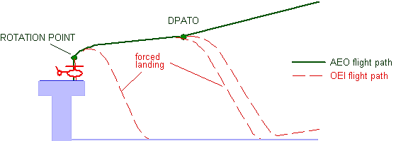
(d)Selection of a lateral visual cue
(1)In order to obtain the maximum performance in the event of an engine failure being recognised at or just after RP, the RP should be at its optimum value, consistent with maintaining the necessary visual cues. If an engine failure is recognised just before RP, the helicopter, if operating at a low mass, may ‘balloon’ a significant height before the reject action has any effect. It is, therefore, important that the pilot flying selects a lateral visual marker and maintains it until the RP is achieved, particularly on decks with few visual cues. In the event of a rejected take-off, the lateral marker will be a vital visual cue in assisting the pilot to carry out a successful landing.
(e)Selection of the rotation point
(1)The optimum RP should be selected to ensure that the take-off path will continue upwards and away from the deck with AEO, but minimising the possibility of hitting the deck edge due to the height loss in the event of an engine failure at or just after RP.
(2)The optimum RP may vary from type to type. Lowering the RP will result in a reduced deck edge clearance in the event of an engine failure being recognised at or just after RP. Raising the RP will result in possible loss of visual cues, or a hard landing in the event of an engine failure just prior to RP.
(f)Pilot reaction times
(1)Pilot reaction time is an important factor affecting deck edge clearance in the event of an engine failure prior to or at RP. Simulation has shown that a delay of 1 second can result in a loss of up to 15 ft in deck edge clearance.
(g)Variation of wind speed
(1)Relative wind is an important parameter in the achieved take-off path following an engine failure; wherever practicable, take-off should be made into wind. Simulation has shown that a 10-kt wind can give an extra 5-ft deck edge clearance compared to a zero wind condition.
(h)Position of the helicopter relative to the deck edge
(1)It is important to position the helicopter as close to the deck edge (including safety nets) as possible whilst maintaining sufficient visual cues, particularly a lateral marker.
(2)The ideal position is normally achieved when the rotor tips are positioned at the forward deck edge. This position minimises the risk of striking the deck edge following recognition of an engine failure at or just after RP. Any take-off heading which causes the helicopter to fly over obstructions below and beyond the deck edge should be avoided if possible. Therefore, the final take-off heading and position will be a compromise between the take-off path for least obstructions, relative wind, turbulence and lateral marker cue considerations.
(i)Actions in the event of an engine failure at or just after RP
(1)Once committed to the continued take-off, it is important, in the event of an engine failure, to rotate the aircraft to the optimum attitude in order to give the best chance of missing the deck edge. The optimum pitch rates and absolute pitch attitudes should be detailed in the profile for the specific type.
(j)Take-off from helidecks that have significant movement
(1)This technique should be used when the helideck movement and any other factors, e.g. insufficient visual cues, makes a successful rejected take-off unlikely. Weight should be reduced to permit an improved one-engine-inoperative capability, as necessary.
(2)The optimum take-off moment is when the helideck is level and at its highest point, e.g. horizontal on top of the swell. Collective pitch should be applied positively and sufficiently to make an immediate transition to climbing forward flight. Because of the lack of a hover, the take-off profile should be planned and briefed prior to lift off from the deck.
(k)Standard landing profile
(1)The approach should be commenced into wind to a point outboard of the helideck. Rotor tip clearance from the helideck edge should be maintained until the aircraft approaches this position at the requisite height (type dependent) with approximately 10 kt of ground-speed and a minimal rate of descent. The aircraft is then flown on a flight path to pass over the deck edge and into a hover over the safe landing area.
Figure 2
Standard landing profile
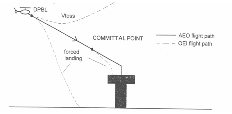
(l)Offset landing profile
(1)If the normal landing profile is impracticable due to obstructions and the prevailing wind velocity, the offset procedure may be used. This should involve flying to a hover position, approximately 90° offset from the landing point, at the appropriate height and maintaining rotor tip clearance from the deck edge. The helicopter should then be flown slowly but positively sideways and down to position in a low hover over the landing point. Normally, the committal point (CP) will be the point at which helicopter begins to transition over the helideck edge.
(m)Training
(1)These techniques should be covered in the training required by Annex III (Part-ORO).
GM1 CAT.POL.H.310 & CAT.POL.H.325 Take-off and landing
ED Decision 2014/015/R
TAKE-OFF AND LANDING TECHNIQUES
(a)This GM describes three types of operation to/from helidecks and elevated FATOs by helicopters operating in performance class 2.
(b)In two cases of take-off and landing, exposure time is used. During the exposure time (which is only approved for use when complying with CAT.POL.H.305), the probability of an engine failure is regarded as extremely remote. If an engine failure occurs during the exposure time, a safe forced landing may not be possible.
(c)Take-off — non-hostile environment (without an approval to operate with an exposure time) CAT.POL.H.310(b).
(1)Figure 1 shows a typical take-off profile for performance class 2 operations from a helideck or an elevated FATO in a non-hostile environment.
(2)If an engine failure occurs during the climb to the rotation point, compliance with CAT.POL.H.310(b) will enable a safe landing or a safe forced landing on the deck.
(3)If an engine failure occurs between the rotation point and the DPATO, compliance with CAT.POL.H.310(b) will enable a safe forced landing on the surface, clearing the deck edge.
(4)At or after the DPATO, the OEI flight path should clear all obstacles by the margins specified in CAT.POL.H.315.
Figure 1
Typical take-off profile PC2 from a helideck/elevated FATO, non-hostile environment
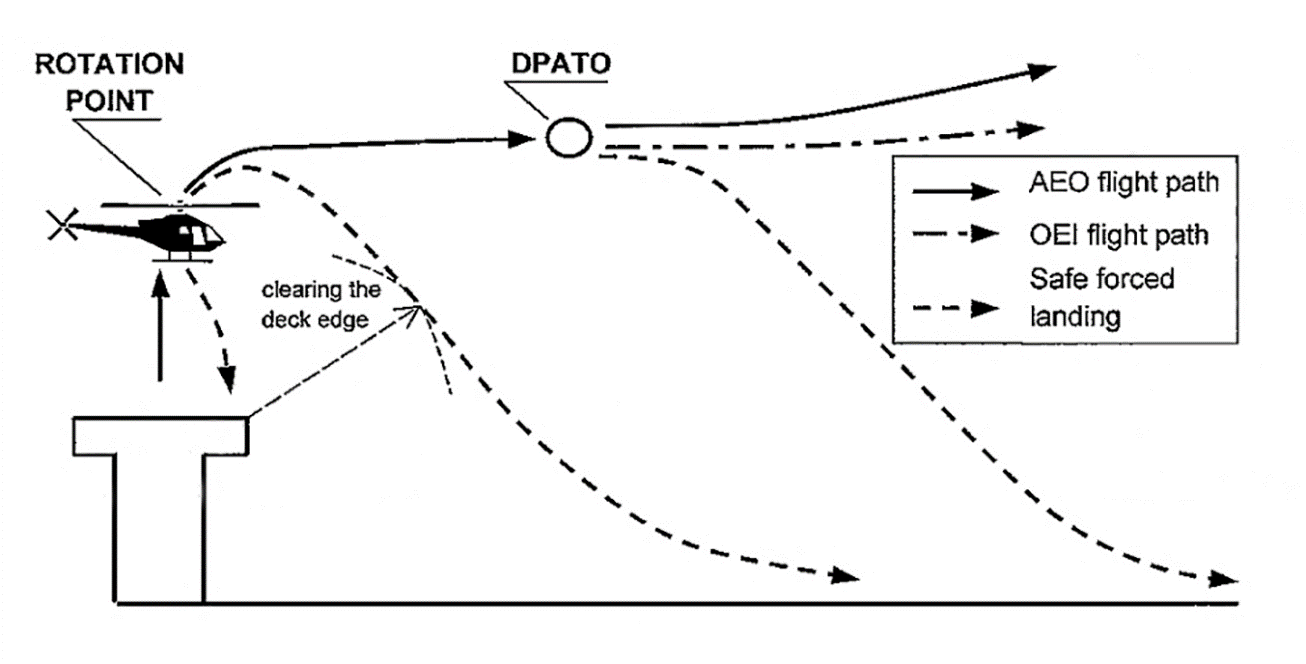
(d)Take-off — non-hostile environment (with exposure time) CAT.POL.H.310(c)
(1)Figure 2 shows a typical take-off profile for performance class 2 operations from a helideck or an elevated FATO in a non-hostile environment (with exposure time).
(2)If an engine failure occurs after the exposure time and before DPATO, compliance with CAT.POL.H.310(c) will enable a safe forced landing on the surface.
(3)At or after the DPATO, the OEI flight path should clear all obstacles by the margins specified in CAT.POL.H.315.
Figure 2
Typical take-off profile PC2 from a helideck/elevated FATO with exposure time, non-hostile environment
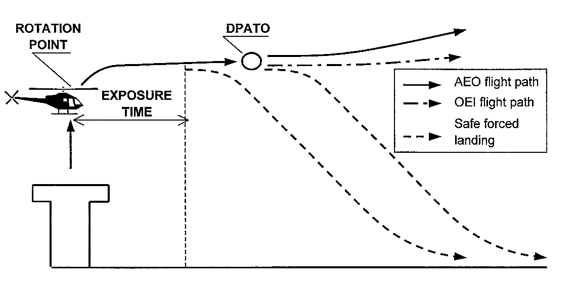
(e)Take-off — non-congested hostile environment (with exposure time) CAT.POL.H.310(c)
(1)Figure 3 shows a typical take off profile for performance class 2 operations from a helideck or an elevated FATO in a non-congested hostile environment (with exposure time).
(2)If an engine failure occurs after the exposure time, the helicopter is capable of a safe forced landing or safe continuation of the flight.
(3)At or after the DPATO, the OEI flight path should clear all obstacles by the margins specified in CAT.POL.H.315.
Figure 3
Typical take-off profile PC2 from a helideck/elevated FATO, non-congested hostile environment
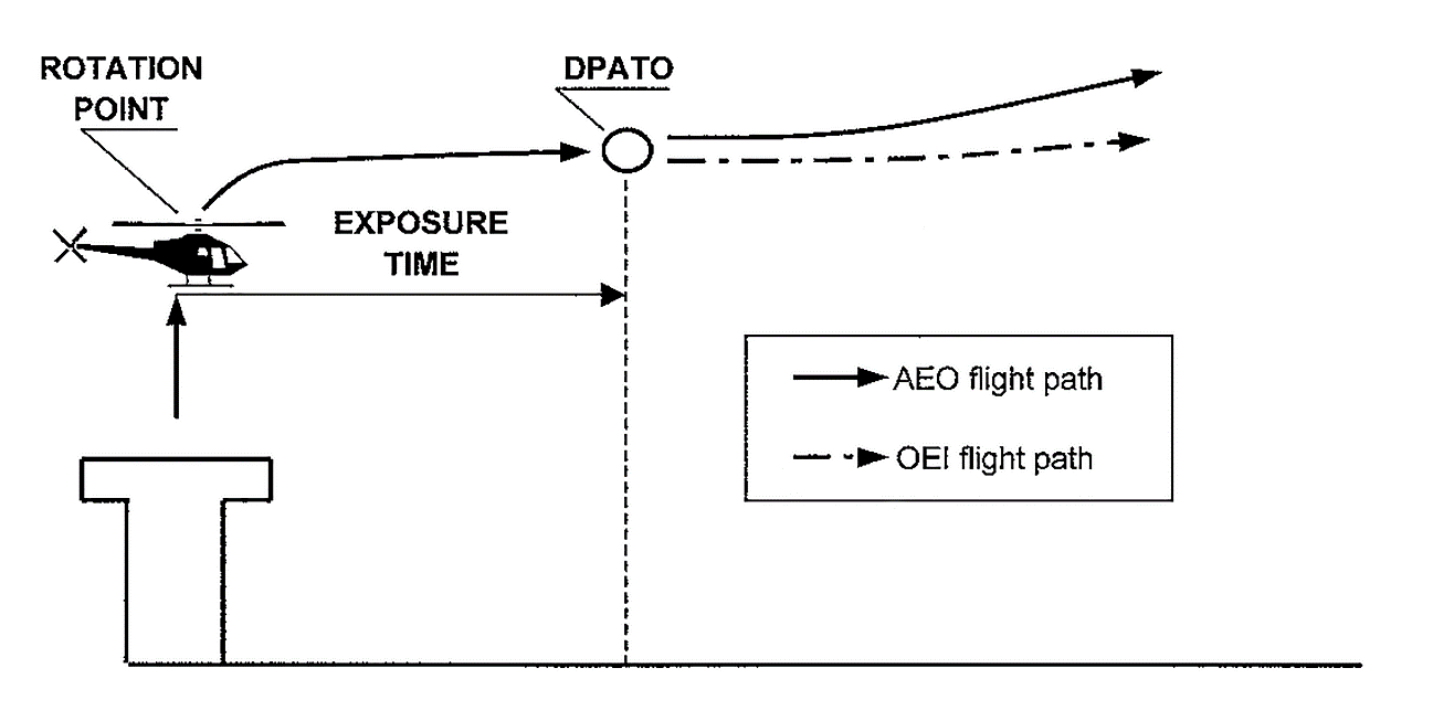
(f)Landing — non-hostile environment (without an approval to operate with an exposure time) CAT.POL.H.325(b)
(1)Figure 4 shows a typical landing profile for performance class 2 operations to a helideck or an elevated FATO in a non-hostile environment.
(2)The DPBL is defined as a ‘window’ in terms of airspeed, rate of descent, and height above the landing surface. If an engine failure occurs before the DPBL, the pilot may elect to land or to execute a balked landing.
(3)In the event of an engine failure being recognised after the DPBL and before the committal point, compliance with CAT.POL.H.325(b) will enable a safe forced landing on the surface.
(4)In the event of an engine failure at or after the committal point, compliance with CAT.POL.H.325(b) will enable a safe forced landing on the deck.
Figure 4
Typical landing profile PC2 to a helideck/elevated FATO, non-hostile environment
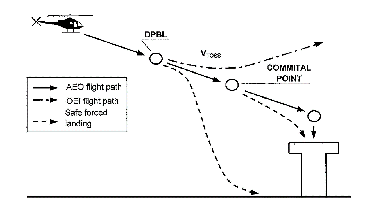
(g)Landing — non-hostile environment (with exposure time) CAT.POL.H.325(c)
(1)Figure 5 shows a typical landing profile for performance class 2 operations to a helideck or an elevated FATO in a non-hostile environment (with exposure time).
(2)The DPBL is defined as a ‘window’ in terms of airspeed, rate of descent, and height above the landing surface. If an engine failure occurs before the DPBL, the pilot may elect to land or to execute a balked landing.
(3)In the event of an engine failure being recognised before the exposure time, compliance with CAT.POL.H.325(c) will enable a safe forced landing on the surface.
(4)In the event of an engine failure after the exposure time, compliance with CAT.POL.H.325(c) will enable a safe forced landing on the deck.
Figure 5
Typical landing profile PC2 to a helideck/elevated FATO with exposure time, non-hostile environment
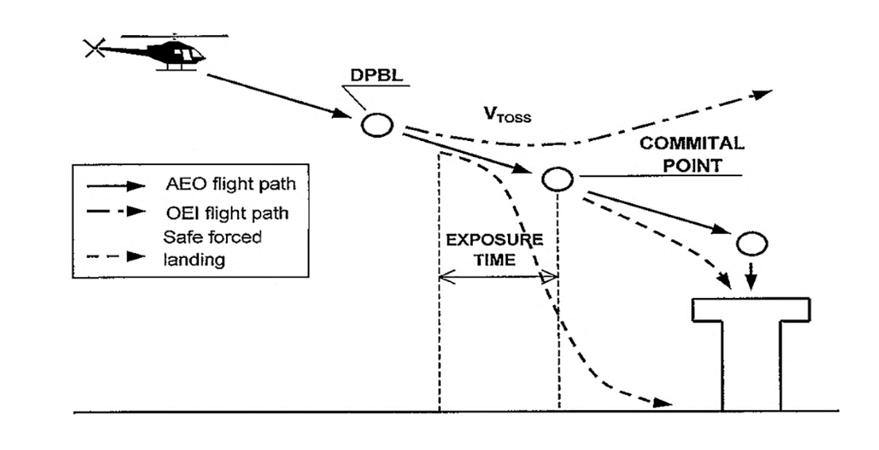
(h)Landing — non-congested hostile environment (with exposure time) CAT.POL.H.325(c)
(1)Figure 6 shows a typical landing profile for performance class 2 operations to a helideck or an elevated FATO in a non-congested hostile environment (with exposure time).
(2)In the event of an engine failure at any point during the approach and landing phase up to the start of exposure time, compliance with CAT.POL.H.325(b) will enable the helicopter, after clearing all obstacles under the flight path, to continue the flight.
(3)In the event of an engine failure after the exposure time (i.e. at or after the committal point), a safe forced landing should be possible on the deck.
Figure 6
Typical landing profile PC2 to a helideck/elevated FATO with exposure time, non-congested hostile environment
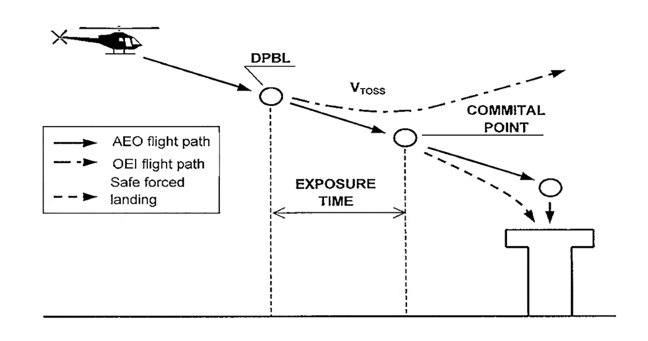
AMC1 CAT.POL.H.310(c)(2) and CAT.POL.H.325(c)(2) Take-off and landing
ED Decision 2016/022/R
FACTORS
(a)To ensure that the necessary factors are taken into account, the operator should:
(1)use take-off and landing procedures that are appropriate to the circumstances, and that minimise the risks of collision with obstacles at the individual offshore location under the prevailing conditions; and
(2)use the aircraft flight manual (AFM) performance data or, where such data is not available, alternative data approved by the competent authority, which show take-off and landing masses that take into account drop-down and take-off deck-edge miss, under varying conditions of pressure altitude, temperature, and wind.
(b)Replanning of offshore location take-off or landing masses during the flight should only be performed in accordance with procedures established in the operations manual (OM). These procedures should be simple and safe to carry out, with no significant increase in the crew workload during critical phases of the flight.
CAT.POL.H.315 Take-off flight path
Regulation (EU) No 965/2012
From the defined point after take-off (DPATO) or, as an alternative, no later than 200 ft above the take-off surface, with the critical engine inoperative, the requirements of CAT.POL.H.210(a)(1), (a)(2) and (b) shall be complied with.
CAT.POL.H.320 En-route – critical engine inoperative
Regulation (EU) No 965/2012
The requirement of CAT.POL.H.215 shall be complied with.
CAT.POL.H.325 Landing
Regulation (EU) No 965/2012
(a)The landing mass at the estimated time of landing shall not exceed the maximum mass specified for a rate of climb of 150 ft/min at 300 m (1 000 ft) above the level of the aerodrome or operating site with the critical engine inoperative and the remaining engine(s) operating at an appropriate power rating.
(b)If the critical engine fails at any point in the approach path:
(1)a balked landing can be carried out meeting the requirement of CAT.POL.H.315; or
(2)for operations other than those specified in CAT.POL.H.305, the helicopter can perform a safe forced landing.
(c)For operations in accordance with CAT.POL.H.305, in addition to the requirements of (a):
(1)the landing mass shall not exceed the maximum mass specified in the AFM for an AEO OGE hover in still air with all engines operating at an appropriate power rating; or
(2)for operations to a helideck:
(i)with a helicopter that has an MOPSC of more than 19; or
(ii)any helicopter operated to a helideck located in a hostile environment,
the landing mass shall take into account the procedure and drop down appropriate to the height of the helideck with the critical engine inoperative and the remaining engine(s) operating at an appropriate power rating.
(d)When showing compliance with (a) to (c), account shall be taken of the appropriate parameters of CAT.POL.H.105(c) at the destination aerodrome or any alternate, if required.
(e)That part of the landing after which the requirement of (b)(1) cannot be met shall be conducted in sight of the surface.
GM1 CAT.POL.H.310 & CAT.POL.H.325 Take-off and landing
ED Decision 2014/015/R
TAKE-OFF AND LANDING TECHNIQUES
(a)This GM describes three types of operation to/from helidecks and elevated FATOs by helicopters operating in performance class 2.
(b)In two cases of take-off and landing, exposure time is used. During the exposure time (which is only approved for use when complying with CAT.POL.H.305), the probability of an engine failure is regarded as extremely remote. If an engine failure occurs during the exposure time, a safe forced landing may not be possible.
(c)Take-off — non-hostile environment (without an approval to operate with an exposure time) CAT.POL.H.310(b).
(1)Figure 1 shows a typical take-off profile for performance class 2 operations from a helideck or an elevated FATO in a non-hostile environment.
(2)If an engine failure occurs during the climb to the rotation point, compliance with CAT.POL.H.310(b) will enable a safe landing or a safe forced landing on the deck.
(3)If an engine failure occurs between the rotation point and the DPATO, compliance with CAT.POL.H.310(b) will enable a safe forced landing on the surface, clearing the deck edge.
(4)At or after the DPATO, the OEI flight path should clear all obstacles by the margins specified in CAT.POL.H.315.
Figure 1
Typical take-off profile PC2 from a helideck/elevated FATO, non-hostile environment
(d)Take-off — non-hostile environment (with exposure time) CAT.POL.H.310(c)
(1)Figure 2 shows a typical take-off profile for performance class 2 operations from a helideck or an elevated FATO in a non-hostile environment (with exposure time).
(2)If an engine failure occurs after the exposure time and before DPATO, compliance with CAT.POL.H.310(c) will enable a safe forced landing on the surface.
(3)At or after the DPATO, the OEI flight path should clear all obstacles by the margins specified in CAT.POL.H.315.
Figure 2
Typical take-off profile PC2 from a helideck/elevated FATO with exposure time, non-hostile environment
(e)Take-off — non-congested hostile environment (with exposure time) CAT.POL.H.310(c)
(1)Figure 3 shows a typical take off profile for performance class 2 operations from a helideck or an elevated FATO in a non-congested hostile environment (with exposure time).
(2)If an engine failure occurs after the exposure time, the helicopter is capable of a safe forced landing or safe continuation of the flight.
(3)At or after the DPATO, the OEI flight path should clear all obstacles by the margins specified in CAT.POL.H.315.
Figure 3
Typical take-off profile PC2 from a helideck/elevated FATO, non-congested hostile environment
(f)Landing — non-hostile environment (without an approval to operate with an exposure time) CAT.POL.H.325(b)
(1)Figure 4 shows a typical landing profile for performance class 2 operations to a helideck or an elevated FATO in a non-hostile environment.
(2)The DPBL is defined as a ‘window’ in terms of airspeed, rate of descent, and height above the landing surface. If an engine failure occurs before the DPBL, the pilot may elect to land or to execute a balked landing.
(3)In the event of an engine failure being recognised after the DPBL and before the committal point, compliance with CAT.POL.H.325(b) will enable a safe forced landing on the surface.
(4)In the event of an engine failure at or after the committal point, compliance with CAT.POL.H.325(b) will enable a safe forced landing on the deck.
Figure 4
Typical landing profile PC2 to a helideck/elevated FATO, non-hostile environment
(g)Landing — non-hostile environment (with exposure time) CAT.POL.H.325(c)
(1)Figure 5 shows a typical landing profile for performance class 2 operations to a helideck or an elevated FATO in a non-hostile environment (with exposure time).
(2)The DPBL is defined as a ‘window’ in terms of airspeed, rate of descent, and height above the landing surface. If an engine failure occurs before the DPBL, the pilot may elect to land or to execute a balked landing.
(3)In the event of an engine failure being recognised before the exposure time, compliance with CAT.POL.H.325(c) will enable a safe forced landing on the surface.
(4)In the event of an engine failure after the exposure time, compliance with CAT.POL.H.325(c) will enable a safe forced landing on the deck.
Figure 5
Typical landing profile PC2 to a helideck/elevated FATO with exposure time, non-hostile environment
(h)Landing — non-congested hostile environment (with exposure time) CAT.POL.H.325(c)
(1)Figure 6 shows a typical landing profile for performance class 2 operations to a helideck or an elevated FATO in a non-congested hostile environment (with exposure time).
(2)In the event of an engine failure at any point during the approach and landing phase up to the start of exposure time, compliance with CAT.POL.H.325(b) will enable the helicopter, after clearing all obstacles under the flight path, to continue the flight.
(3)In the event of an engine failure after the exposure time (i.e. at or after the committal point), a safe forced landing should be possible on the deck.
Figure 6
Typical landing profile PC2 to a helideck/elevated FATO with exposure time, non-congested hostile environment
CHAPTER 4 – Performance class 3
CAT.POL.H.400 General
Regulation (EU) No 965/2012
(a)Helicopters operated in performance class 3 shall be certified in category A or equivalent as determined by the Agency, or category B.
(b)Operations shall only be conducted in a non-hostile environment, except:
(1)when operating in accordance with ; or
(2)for the take-off and landing phase, when operating in accordance with (c).
(c)Provided the operator is approved in accordance with CAT.POL.H.305, operations may be conducted to/from an aerodrome or operating site located outside a congested hostile environment without an assured safe forced landing capability:
(1)during take-off, before reaching Vy (speed for best rate of climb) or 200 ft above the take-off surface; or
(2)during landing, below 200 ft above the landing surface.
(d)Operations shall not be conducted:
(1)out of sight of the surface;
(2)at night;
(3)when the ceiling is less than 600 ft; or
(4)when the visibility is less than 800 m.
GM1 CAT.POL.H.400(c) General
ED Decision 2022/012/R
THE TAKE-OFF AND LANDING PHASES (PERFORMANCE CLASS 3)
(a)To understand the use of ground level exposure in performance class 3, it is important first to be aware of the logic behind the use of ‘take-off and landing phases’. Once this is clear, it is easier to appreciate the aspects and limits of the use of ground level exposure. This GM shows the derivation of the term from the ICAO definition of the ‘en-route phase’ and then gives practical examples of the use, and limitations on the use, of ground level exposure in CAT.POL.400(c).
(b)The take-off phase in performance class 1 and performance class 2 may be considered to be bounded by ‘the specified point in the take-off’ from which the take-off flight path begins.
(1)In performance class 1, this specified point is defined as ‘the end of the take-off distance required’.
(2)In performance class 2, this specified point is defined as DPATO or, as an alternative, no later than 200 ft above the take-off surface.
(3)There is no simple equivalent point for bounding of the landing in performance classes 1 & 2.
(c)Take-off flight path is not used in performance class 3 and, consequently, the term ‘take-off and landing phases’ is used to bound the limit of exposure. For the purpose of performance class 3, the take-off and landing phases are as set out in CAT.POL.H.400(c) and are considered to be bounded by:
(1)during take-off before reaching Vy (speed for best rate of climb) or 200 ft above the take-off surface; and
(2)during landing, below 200 ft above the landing surface.
(ICAO Annex 6 Part III, defines en-route phase as being ‘That part of the flight from the end of the take-off and initial climb phase to the commencement of the approach and landing phase.’ The use of take-off and landing phase in this text is used to distinguish the take-off from the initial climb, and the landing from the approach: they are considered to be complementary and not contradictory.)
(d)Ground level exposure — and exposure for elevated FATOs or helidecks in a non-hostile environment — is permitted for operations under an approval in accordance with CAT.POL.H.305. Exposure in this case is limited to the ‘take-off and landing phases’.
The practical effect of bounding of exposure can be illustrated with the following examples:
(1)A clearing: the operator may consider a take-off/landing in a clearing when there is sufficient power, with all engines operating, to clear all obstacles in the take-off path by an adequate margin (this, in ICAO, is meant to indicate 35 ft). Thus, the clearing may be bounded by bushes, fences, wires and, in the extreme, by power lines, high trees, etc. Once the obstacle has been cleared, by using a steep or a vertical climb (which itself may infringe the height velocity (HV) diagram), the helicopter reaches Vy or 200 ft, and from that point a safe forced landing must be possible. The effect is that whilst operation to a clearing is possible, operation to a clearing in the middle of a forest is not (except when operated in accordance with CAT.POL.H.420).
(2)An aerodrome/operating site surrounded by rocks: the same applies when operating to a landing site that is surrounded by rocky ground. Once Vy or 200 ft has been reached, a safe forced landing must be possible.
(3)An elevated FATO or helideck: when operating to an elevated FATO or helideck in performance class 3, exposure is considered to be twofold: firstly, to a deck-edge strike if the engine fails after the decision to transition has been taken; and secondly, to operations in the HV diagram due to the height of the FATO or helideck. Once the takeoff surface has been cleared and the helicopter has reached the knee of the HV diagram, the helicopter should be capable of making a safe forced landing.
(e)Operation in accordance with CAT.POL.400(b) does not permit excursions into a hostile environment as such and is specifically concerned with the absence of space to abort the takeoff or landing when the take-off and landing space are limited; or when operating in the HV diagram.
(f)Specifically, the use of this exception to the requirement for a safe forced landing (during takeoff or landing) does not permit semi-continuous operations over a hostile environment such as a forest or hostile sea area.
CAT.POL.H.405 Take-off
Regulation (EU) No 965/2012
(a)The take-off mass shall be the lower of:
(1)the MCTOM; or
(2)the maximum take-off mass specified for a hover in ground effect with all engines operating at take-off power, or if conditions are such that a hover in ground effect is not likely to be established, the take-off mass specified for a hover out of ground effect with all engines operating at take-off power.
(b)Except as provided in CAT.POL.H.400(b), in the event of an engine failure the helicopter shall be able to perform a safe forced landing.
CAT.POL.H.410 En-route
Regulation (EU) No 965/2012
(a)The helicopter shall be able, with all engines operating within the maximum continuous power conditions, to continue along its intended route or to a planned diversion without flying at any point below the appropriate minimum flight altitude.
(b)Except as provided in CAT.POL.H.420, in the event of an engine failure the helicopter shall be able to perform a safe forced landing.
CAT.POL.H.415 Landing
Regulation (EU) No 965/2012
(a)The landing mass of the helicopter at the estimated time of landing shall be the lower of:
(1)the maximum certified landing mass; or
(2)the maximum landing mass specified for a hover in ground effect, with all engines operating at take-off power, or if conditions are such that a hover in ground effect is not likely to be established, the landing mass for a hover out of ground effect with all engines operating at take-off power.
(b)Except as provided in CAT.POL.H.400(b), in the event of an engine failure, the helicopter shall be able to perform a safe forced landing.
CAT.POL.H.420 Helicopter operations over a hostile environment located outside a congested area
Regulation (EU) 2023/1020
(a)Operations over a non-congested hostile environment without a safe forced landing capability with turbine-powered helicopters with an MOPSC of six or less shall only be conducted if the operator has been granted an approval by the competent authority, following a safety risk assessment performed by the operator. Before such operations take place in another Member State, the operator shall obtain an endorsement from the competent authority of that State.
(b)To obtain and maintain such approval, the operator shall:
(1)only conduct the operations referred to in point (a) in the areas and under the conditions specified in the approval;
(2)INTENTIONALLY LEFT BLANK
(3)substantiate that helicopter limitations, or other justifiable considerations, preclude the use of the appropriate performance criteria;
(4)be approved in accordance with point CAT.POL.H.305(b).
(c)Notwithstanding CAT.IDE.H.240, such operations may be conducted without supplemental oxygen equipment, provided the cabin altitude does not exceed 10 000 ft for a period in excess of 30 minutes and never exceeds 13 000 ft pressure altitude.
AMC1 CAT.POL.H.420 Helicopter operations over a hostile environment located outside a congested area
ED Decision 2014/015/R
SAFETY RISK ASSESSMENT
(a)Introduction
Two cases that are deemed to be acceptable for the alleviation under the conditions of CAT.POL.H.420 for the en-route phase of the flight (operations without an assured safe forced landing capability during take-off and landing phases are subject to a separate approval under CAT.POL.H.400(c)) are flights over mountainous areas and remote areas, both already having been considered by the JAA in comparison to ground transport in the case of remote areas and respectively to multi-engined helicopters in the case of mountain areas.
(1)Remote areas
Remote area operation is acceptable when alternative surface transportation does not provide the same level of safety as helicopter transportation. In this case, the operator should demonstrate why the economic circumstances do not justify replacement of single-engined helicopters by multi-engined helicopters.
(2)Mountainous areas
Current generation twin-engined helicopters may not be able to meet the performance class 1 or 2 requirements at the operational altitude; consequently, the outcome of an engine failure is the same as a single-engined helicopter. In this case, the operator should justify the use of exposure in the en-route phase.
(b)Other areas of operation
For other areas of operations to be considered for the operational approval, a risk assessment should be conducted by the operator that should, at least, consider the following factors:
(1)type of operations and the circumstances of the flight;
(2)area/terrain over which the flight is being conducted;
(3)probability of an engine failure and the consequence of such an event;
(4)safety target;
(5)procedures to maintain the reliability of the engine(s);
(6)installation and utilisation of a usage monitoring system; and
(7)when considered relevant, any available publications on (analysis of) accident or other safety data.
GM1 CAT.POL.H.420 Helicopter operations over a hostile environment located outside a congested area
ED Decision 2014/015/R
EXAMPLE OF A SAFETY RISK ASSESSMENT
(a)Introduction
Where it can be substantiated that helicopter limitations, or other justifiable considerations, preclude the use of appropriate performance, the approval effectively alleviates from compliance with the requirement in CAT.OP.MPA.137, that requires the availability of surfaces that permit a safe forced landing to be executed.
Circumstances where an engine failure will result in a catastrophic event are those defined for a hostile environment:
(1)a lack of adequate surfaces to perform a safe landing;
(2)the inability to protect the occupants of the helicopter from the elements; or
(3)a lack of search and rescue services to provide rescue consistent with the expected survival time in such environment.
(b)The elements of the risk assessment
The risk assessment process consists of the application of three principles:
—a safety target;
—a helicopter reliability assessment; and
—continuing airworthiness.
(1)The safety target
The main element of the risk assessment when exposure was initially introduced by the JAA into JAR-OPS 3 (NPA OPS-8), was the assumption that turbine engines in helicopters would have failure rates of about 1:100 000 per flying hour — which would permit (against the agreed safety target of 5 x 10⁻⁸ per event) an exposure of about 9 seconds for twin-engined helicopters and 18 seconds for single-engined helicopters during the take-off or landing event.
An engine failure in the en-route phase over a hostile environment will inevitably result in a higher risk (in the order of magnitude of 1 x 10⁻⁵ per flying hour) to a catastrophic event.
The approval to operate with this high risk of endangering the helicopter occupants should, therefore, only be granted against a comparative risk assessment (i.e. compared to other means of transport, the risk is demonstrated to be lower), or where there is no economic justification to replace single-engined helicopters by multi-engined helicopters.
(2)The reliability assessment
The purpose of the reliability assessment is to ensure that the engine reliability remains at or better than 1 x 10⁻⁵.
(3)Continuing airworthiness
Mitigating procedures consist of a number of elements:
(i)the fulfilment of all manufacturers’ safety modifications;
(ii)a comprehensive reporting system (both failures and usage data); and
(iii)the implementation of a usage monitoring system (UMS).
Each of these elements is to ensure that engines, once shown to be sufficiently reliable to meet the safety target, will sustain such reliability (or improve upon it).
The monitoring system is felt to be particularly important as it had already been demonstrated that when such systems are in place, it inculcates a more considered approach to operations. In addition, the elimination of ‘hot starts’, prevented by the UMS, itself minimises the incidents of turbine burst failures.
GM2 CAT.POL.H.420(a) Helicopter operations over a hostile environment located outside a congested area
ED Decision 2014/015/R
ENDORSEMENT FROM ANOTHER STATE
(a)Application to another State
To obtain an endorsement from another State, the operator should submit to that State the safety risk assessment and the reasons and justification that preclude the use of appropriate performance criteria, over those hostile areas outside a congested area over which the operator is planning to conduct operations.
(b)Endorsement from another State
Upon receiving the endorsement from another State, the operator should submit it together with the safety risk assessment and the reasons and justification that preclude the use of appropriate performance criteria, to the competent authority issuing the AOC to obtain the approval or extend the existing approval to a new area.
SECTION 3 – Mass and balance
CHAPTER 1 – Motor-powered aircraft
CAT.POL.MAB.100 Mass and balance, loading
Regulation (EU) No 965/2012
(a)During any phase of operation, the loading, mass and centre of gravity (CG) of the aircraft shall comply with the limitations specified in the AFM, or the operations manual if more restrictive.
(b)The operator shall establish the mass and the CG of any aircraft by actual weighing prior to initial entry into service and thereafter at intervals of four years if individual aircraft masses are used, or nine years if fleet masses are used. The accumulated effects of modifications and repairs on the mass and balance shall be accounted for and properly documented. Aircraft shall be reweighed if the effect of modifications on the mass and balance is not accurately known.
(c)The weighing shall be accomplished by the manufacturer of the aircraft or by an approved maintenance organisation.
(d)The operator shall determine the mass of all operating items and crew members included in the aircraft dry operating mass by weighing or by using standard masses. The influence of their position on the aircraft’s CG shall be determined.
(e)The operator shall establish the mass of the traffic load, including any ballast, by actual weighing or by determining the mass of the traffic load in accordance with standard passenger and baggage masses.
(f)In addition to standard masses for passengers and checked baggage, the operator can use standard masses for other load items, if it demonstrates to the competent authority that these items have the same mass or that their masses are within specified tolerances.
(g)The operator shall determine the mass of the fuel load by using the actual density or, if not known, the density calculated in accordance with a method specified in the operations manual.
(h)The operator shall ensure that the loading of:
(1)its aircraft is performed under the supervision of qualified personnel; and
(2)traffic load is consistent with the data used for the calculation of the aircraft mass and balance.
(i)The operator shall comply with additional structural limits such as the floor strength limitations, the maximum load per running metre, the maximum mass per cargo compartment and the maximum seating limit. For helicopters, in addition, the operator shall take account of in-flight changes in loading.
(j)The operator shall specify, in the operations manual, the principles and methods involved in the loading and in the mass and balance system that meet the requirements contained in (a) to (i). This system shall cover all types of intended operations.
AMC1 CAT.POL.MAB.100(a) Mass and balance, loading
ED Decision 2014/015/R
CENTRE OF GRAVITY LIMITS — OPERATIONAL CG ENVELOPE AND IN-FLIGHT CG
In the Certificate Limitations section of the AFM, forward and aft CG limits are specified. These limits ensure that the certification stability and control criteria are met throughout the whole flight and allow the proper trim setting for take-off. The operator should ensure that these limits are respected by:
(a)Defining and applying operational margins to the certified CG envelope in order to compensate for the following deviations and errors:
(1)Deviations of actual CG at empty or operating mass from published values due, for example, to weighing errors, unaccounted modifications and/or equipment variations.
(2)Deviations in fuel distribution in tanks from the applicable schedule.
(3)Deviations in the distribution of baggage and cargo in the various compartments as compared with the assumed load distribution as well as inaccuracies in the actual mass of baggage and cargo.
(4)Deviations in actual passenger seating from the seating distribution assumed when preparing the mass and balance documentation. Large CG errors may occur when ‘free seating’, i.e. freedom of passengers to select any seat when entering the aircraft, is permitted. Although in most cases reasonably even longitudinal passenger seating can be expected, there is a risk of an extreme forward or aft seat selection causing very large and unacceptable CG errors, assuming that the balance calculation is done on the basis of an assumed even distribution. The largest errors may occur at a load factor of approximately 50% if all passengers are seated in either the forward or aft half of the cabin. Statistical analysis indicates that the risk of such extreme seating adversely affecting the CG is greatest on small aircraft.
(5)Deviations of the actual CG of cargo and passenger load within individual cargo compartments or cabin sections from the normally assumed mid position.
(6)Deviations of the CG caused by gear and flap positions and by application of the prescribed fuel usage procedure, unless already covered by the certified limits.
(7)Deviations caused by in-flight movement of cabin crew, galley equipment and passengers.
(8)On small aeroplanes, deviations caused by the difference between actual passenger masses and standard passenger masses when such masses are used.
(b)Defining and applying operational procedures in order to:
(1)ensure an even distribution of passengers in the cabin;
(2)take into account any significant CG travel during flight caused by passenger/crew movement; and
(3)take into account any significant CG travel during flight caused by fuel consumption/transfer.
AMC1 CAT.POL.MAB.100(b) Mass and balance, loading
ED Decision 2014/015/R
WEIGHING OF AN AIRCRAFT
(a)New aircraft that have been weighed at the factory may be placed into operation without reweighing if the mass and balance records have been adjusted for alterations or modifications to the aircraft. Aircraft transferred from one EU operator to another EU operator do not have to be weighed prior to use by the receiving operator unless more than 4 years have elapsed since the last weighing.
(b)The mass and centre of gravity (CG) position of an aircraft should be revised whenever the cumulative changes to the dry operating mass exceed ±0.5 % of the maximum landing mass or, for aeroplanes, the cumulative change in CG position exceeds 0.5 % of the mean aerodynamic chord. This may be done by weighing the aircraft or by calculation. If the AFM requires to record changes to mass and CG position below these thresholds, or to record changes in any case, and make them known to the commander, mass and CG position should be revised accordingly and made known to the commander.
(c)When weighing an aircraft, normal precautions should be taken consistent with good practices such as:
(1)checking for completeness of the aircraft and equipment;
(2)determining that fluids are properly accounted for;
(3)ensuring that the aircraft is clean; and
(4)ensuring that weighing is accomplished in an enclosed building.
(d)Any equipment used for weighing should be properly calibrated, zeroed, and used in accordance with the manufacturer's instructions. Each scale should be calibrated either by the manufacturer, by a civil department of weights and measures or by an appropriately authorised organisation within two years or within a time period defined by the manufacturer of the weighing equipment, whichever is less. The equipment should enable the mass of the aircraft to be established accurately. One single accuracy criterion for weighing equipment cannot be given. However, the weighing accuracy is considered satisfactory if the accuracy criteria in Table1 are met by the individual scales/cells of the weighing equipment used:
Table 1
Accuracy criteria for weighing equipment
For a scale/cell load | An accuracy of |
below 2 000 kg | ±1 % |
from 2 000 kg to 20 000 kg | ±20 kg |
above 20 000 kg | ±0.1 % |