
Filters
AMC1 NCC.POL.105(c) Mass and balance, loading
ED Decision 2013/021/R
DRY OPERATING MASS
(a)The dry operating mass should include:
(1)crew and crew baggage;
(2)catering and removable passenger service equipment; and
(3)tank water and lavatory chemicals.
(b)The operator should correct the dry operating mass to account for any additional crew baggage. The position of this additional baggage should be accounted for when establishing the centre of gravity of the aircraft.
(c)The operator should establish a procedure in the operations manual to determine when to select actual or standard masses for crew members.
(d)When determining the actual mass by weighing, crew members’ personal belongings and hand baggage should be included. Such weighing should be conducted immediately prior to boarding the aircraft.
AMC1 NCC.POL.105(d) Mass and balance, loading
ED Decision 2013/021/R
MASS VALUES FOR PASSENGERS AND BAGGAGE
(a)The predetermined mass for hand baggage and clothing should be established by the operator on the basis of studies relevant to its particular operation. In any case, it should not be less than:
(1)4 kg for clothing; and
(2)6 kg for hand baggage.
The passengers’ stated mass and the mass of passengers’ clothing and hand baggage should be checked prior to boarding and adjusted, if necessary. The operator should establish a procedure in the operations manual when to select actual or standard masses and the procedure to be followed when using verbal statements.
(b)When determining the actual mass by weighing, passengers’ personal belongings and hand baggage should be included. Such weighing should be conducted immediately prior to boarding the aircraft.
(c)When determining the mass of passengers by using standard mass values, provided in Tables 1 and 2 of NCC.POL.105(e), infants occupying separate passenger seats should be considered as children for the purpose of this AMC. When the total number of passenger seats available on an aircraft is 20 or more, the standard masses for males and females in Table 1 of NCC.POL.105(e) should be used. As an alternative, in cases where the total number of passenger seats available is 30 or more, the ‘All Adult’ mass values in Table 1 of NCC.POL.105(e) may be used.
On aeroplane flights with 19 passenger seats or less and all helicopter flights where no hand baggage is carried in the cabin or where hand baggage is accounted for separately, 6 kg may be deducted from male and female masses in Table 2 of NCC.POL.105(e). Articles such as an overcoat, an umbrella, a small handbag or purse, reading material or a small camera are not considered as hand baggage.
For helicopter operations in which a survival suit is provided to passengers, 3 kg should be added to the passenger mass value.
(d)Mass values for baggage.
The mass of checked baggage should be checked prior to loading and increased, if necessary.
(e)On any flight identified as carrying a significant number of passengers whose masses, including hand baggage, are expected to significantly deviate from the standard passenger mass, the operator should determine the actual mass of such passengers by weighing or by adding an adequate mass increment.
(f)If standard mass values for checked baggage are used and a significant number of passengers’ checked baggage is expected to significantly deviate from the standard baggage mass, the operator should determine the actual mass of such baggage by weighing or by adding an adequate mass increment.
GM1 NCC.POL.105(d) Mass and balance, loading
ED Decision 2013/021/R
ADJUSTMENT OF STANDARD MASSES
When standard mass values are used, item (e) of AMC1 NCC.POL.105(d) states that the operator should identify and adjust the passenger and checked baggage masses in cases where significant numbers of passengers or quantities of baggage are suspected of significantly deviating from the standard values. Therefore, the operations manual should contain instructions to ensure that:
(a)check-in, operations and loading personnel as well as cabin and flight crew report or take appropriate action when a flight is identified as carrying a significant number of passengers whose masses, including hand baggage, are expected to significantly deviate from the standard passenger mass, and/or groups of passengers carrying exceptionally heavy baggage; and
(b)on small aircraft, where the risks of overload and/or CG errors are the greatest, pilots pay special attention to the load and its distribution and make proper adjustments.
GM1 NCC.POL.105(e) Mass and balance, loading
ED Decision 2021/005/R
TYPE OF FLIGHTS
(a)For the purpose of Table 3 of NCC.POL.105(e):
(1)domestic flight means a flight with origin and destination within the borders of one State.
(2)flights within the European region means flights, other than domestic flights, whose origin and destination are within the area specified in item (b).
(3)Intercontinental flight means flights beyond the European region with origin and destination in different continents.
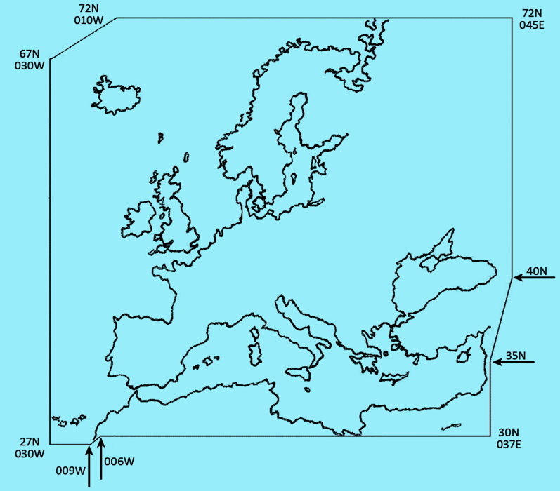
(b)Flights within the European region are flights conducted within the following area:
—N7200E04500
—N4000E04500
—N3500E03700
—N3000E03700
—N3000W00600
—N2700W00900
—N2700W03000
—N6700W03000
—N7200W01000
—N7200E04500
as depicted in Figure 1: European region.
Figure 1:
The European region
GM1 NCC.POL.105(g) Mass and balance, loading
ED Decision 2013/021/R
FUEL DENSITY
(a)If the actual fuel density is not known, the operator may use standard fuel density values for determining the mass of the fuel load. Such standard values should be based on current fuel density measurements for the airports or areas concerned.
(b)Typical fuel density values are:
(1)Gasoline (reciprocating engine fuel) –0.71
(2)JET A1 (Jet fuel JP 1) –0.79
(3)JET B (Jet fuel JP 4) –0.76
(4)Oil –0.88
NCC.POL.110 Mass and balance data and documentation
Regulation (EU) 2021/1296
(a)The operator shall establish mass and balance data and produce mass and balance documentation prior to each flight specifying the load and its distribution in such a way that the mass and balance limits of the aircraft are not exceeded. The mass and balance documentation shall contain the following information:
(1)aircraft registration and type;
(2)flight identification, number and date, as applicable;
(3)name of the pilot-in-command;
(4)name of the person who prepared the document;
(5)dry operating mass and the corresponding CG of the aircraft;
(6)mass of the fuel/energy at take-off and mass of trip fuel/energy;
(7)mass of consumables other than fuel/energy, if applicable;
(8)load components including passengers, baggage, freight, and ballast;
(9)take-off mass, landing mass, and zero fuel/energy mass;
(10)applicable aircraft CG positions; and
(11)the limiting mass and CG values.
(b)Where mass and balance data and documentation are generated by a computerised mass and balance system, the operator shall verify the integrity of the output data.
(c)When the loading of the aircraft is not supervised by the pilot-in-command, the person supervising the loading of the aircraft shall confirm by hand signature or equivalent that the load and its distribution are in accordance with the mass and balance documentation established by the pilot-in-command. The pilot-in-command shall indicate his/her acceptance by hand signature or equivalent.
(d)The operator shall specify procedures for last minute changes to the load to ensure that:
(1)any last minute change after the completion of the mass and balance documentation is entered in the flight planning documents containing the mass and balance documentation;
(2)the maximum last minute change allowed in passenger numbers or hold load is specified; and
(3)new mass and balance documentation is prepared if this maximum number is exceeded.
AMC1 NCC.POL.110(a) Mass and balance data and documentation
ED Decision 2013/021/R
CONTENTS
The mass and balance documentation should include advice to the pilot-in-command whenever a non-standard method has been used for determining the mass of the load.
AMC2 NCC.POL.110(b) Mass and balance data and documentation
ED Decision 2013/021/R
INTEGRITY
The operator should verify the integrity of mass and balance data and documentation generated by a computerised mass and balance system, at intervals not exceeding 6 months. The operator should establish a system to check that amendments of its input data are incorporated properly in the system and that the system is operating correctly on a continuous basis.
AMC1 NCC.POL.110(c) Mass and balance data and documentation
ED Decision 2013/021/R
SIGNATURE OR EQUIVALENT
Where a signature by hand is impracticable or it is desirable to arrange the equivalent verification by electronic means, the following conditions should be applied in order to make an electronic signature the equivalent of a conventional hand-written signature:
(a)electronic ‘signing’ by entering a personal identification number (PIN) code with appropriate security, etc.;
(b)entering the PIN code generates a print-out of the individual’s name and professional capacity on the relevant document(s) in such a way that it is evident, to anyone having a need for that information, who has signed the document;
(c)the computer system logs information to indicate when and where each PIN code has been entered;
(d)the use of the PIN code is, from a legal and responsibility point of view, considered to be fully equivalent to signature by hand;
(e)the requirements for record keeping remain unchanged; and
(f)all personnel concerned are made aware of the conditions associated with electronic signature and this is documented.
AMC2 NCC.POL.110(c) Mass and balance data and documentation
ED Decision 2013/021/R
MASS AND BALANCE DOCUMENTATION SENT VIA DATA LINK
Whenever the mass and balance documentation is sent to the aircraft via data link, a copy of the final mass and balance documentation as accepted by the pilot-in-command should be available on the ground.
GM1 NCC.POL.110(b) Mass and balance data and documentation
ED Decision 2013/021/R
ON-BOARD INTEGRATED MASS AND BALANCE COMPUTER SYSTEM
An on-board integrated mass and balance computer system may be an aircraft installed system capable of receiving input data either from other aircraft systems or from a mass and balance system on the ground, in order to generate mass and balance data as an output.
GM2 NCC.POL.110(b) Mass and balance data and documentation
ED Decision 2013/021/R
STAND-ALONE COMPUTERISED MASS AND BALANCE SYSTEM
A stand-alone computerised mass and balance system may be a computer, either as part of an electronic flight bag (EFB) system or solely dedicated to mass and balance purposes, requiring input from the user, in order to generate mass and balance data as an output.
NCC.POL.111 Mass and balance data and documentation – alleviations
Regulation (EU) No 800/2013
Notwithstanding NCC.POL.110(a)(5), the CG position may not need to be on the mass and balance documentation, if the load distribution is in accordance with a pre-calculated balance table or if it can be shown that for the planned operations a correct balance can be ensured, whatever the real load is.
NCC.POL.115 Performance – general
Regulation (EU) No 800/2013
The pilot-in-command shall only operate the aircraft if the performance is adequate to comply with the applicable rules of the air and any other restrictions applicable to the flight, the airspace or the aerodromes or operating sites used, taking into account the charting accuracy of any charts and maps used.
NCC.POL.120 Take-off mass limitations – aeroplanes
Regulation (EU) No 800/2013
The operator shall ensure that:
(a)the mass of the aeroplane at the start of take-off shall not exceed the mass limitations:
(1)at take-off as required in NCC.POL.125;
(2)en-route with one engine inoperative (OEI) as required in NCC.POL.130; and
(3)at landing as required in NCC.POL.135;
allowing for expected reductions in mass as the flight proceeds and for fuel jettisoning;
(b)the mass at the start of take-off shall never exceed the maximum take-off mass specified in the AFM for the pressure altitude appropriate to the elevation of the aerodrome or operating site, and if used as a parameter to determine the maximum take-off mass, any other local atmospheric condition; and
(c)the estimated mass for the expected time of landing at the aerodrome or operating site of intended landing and at any destination alternate aerodrome shall never exceed the maximum landing mass specified in the AFM for the pressure altitude appropriate to the elevation of those aerodromes or operating sites, and if used as a parameter to determine the maximum landing mass, any other local atmospheric condition.
NCC.POL.125 Take-off – aeroplanes
Regulation (EU) No 379/2014
(a)When determining the maximum take-off mass, the pilot-in-command shall take the following into account:
(1)the calculated take-off distance shall not exceed the take-off distance available with a clearway distance not exceeding half of the take-off run available;
(2)the calculated take-off run shall not exceed the take-off run available;
(3)a single value of V1 shall be used for the rejected and continued take-off, where a V1 is specified in the AFM; and
(4)on a wet or contaminated runway, the take-off mass shall not exceed that permitted for a take-off on a dry runway under the same conditions.
(b)Except for an aeroplane equipped with turboprop engines and a maximum take-off mass at or below 5 700 kg, in the event of an engine failure during take-off, the pilot-in-command shall ensure that the aeroplane is able:
(1)to discontinue the take-off and stop within the accelerate-stop distance available or the runway available; or
(2)to continue the take-off and clear all obstacles along the flight path by an adequate margin until the aeroplane is in a position to comply with NCC.POL.130.
AMC1 NCC.POL.125 Take-off — aeroplanes
ED Decision 2013/021/R
TAKE-OFF MASS
The following should be considered for determining the maximum take-off mass:
(a)the pressure altitude at the aerodrome;
(b)the ambient temperature at the aerodrome;
(c)the runway surface condition and the type of runway surface;
(d)the runway slope in the direction of take-off;
(e)not more than 50 % of the reported head-wind component or not less than 150 % of the reported tailwind component; and
(f)the loss, if any, of runway length due to alignment of the aeroplane prior to take-off.
AMC2 NCC.POL.125 Take-off – aeroplanes
ED Decision 2013/021/R
CONTAMINATED RUNWAY PERFORMANCE DATA
Wet and contaminated runway performance data, if made available by the manufacturer, should be taken into account. If such data is not made available, the operator should account for wet and contaminated runway conditions by using the best information available.
AMC3 NCC.POL.125 Take-off – aeroplanes
ED Decision 2013/021/R
ADEQUATE MARGIN
The adequate margin should be defined in the operations manual.
GM1 NCC.POL.125 Take-off – aeroplanes
ED Decision 2021/005/R
RUNWAY SURFACE CONDITION
Operation on runways contaminated with water, slush, snow or ice implies uncertainties with regard to runway friction and contaminant drag and therefore to the achievable performance and control of the aeroplane during take-off or landing, since the actual conditions may not completely match the assumptions on which the performance information is based. In the case of a contaminated runway, the first option for the pilot-in-command is to wait until the runway is cleared. If this is impracticable, he or she may consider a take-off or landing, provided that he or she has applied the applicable performance adjustments, and any further safety measures he or she considers justified under the prevailing conditions. The excess runway length available including the criticality of the overrun area should also be considered.
The determination of take-off performance data for wet and contaminated runways should be based on the reported runway surface condition in terms of contaminant and depth.
GM2 NCC.POL.125 Take-off – aeroplanes
ED Decision 2013/021/R
ADEQUATE MARGIN
‘An adequate margin’ is illustrated by the appropriate examples included in Attachment C to ICAO Annex 6, Part I.
NCC.POL.130 En-route – one engine inoperative – aeroplanes
Regulation (EU) No 800/2013
The pilot-in-command shall ensure that in the event of an engine becoming inoperative at any point along the route, a multi-engined aeroplane shall be able to continue the flight to an adequate aerodrome or operating site without flying below the minimum obstacle clearance altitude at any point.
NCC.POL.135 Landing – aeroplanes
Regulation (EU) No 800/2013
The pilot-in-command shall ensure that at any aerodrome or operating site, after clearing all obstacles in the approach path by a safe margin, the aeroplane shall be able to land and stop, or a seaplane to come to a satisfactorily low speed, within the landing distance available. Allowance shall be made for expected variations in the approach and landing techniques, if such allowance has not been made in the scheduling of performance data.
AMC1 NCC.POL.135 Landing – aeroplanes
ED Decision 2013/021/R
GENERAL
The following should be considered to ensure that an aeroplane is able to land and stop, or a seaplane to come to a satisfactorily low speed, within the landing distance available:
(a)the pressure altitude at the aerodrome;
(b)the runway surface condition and the type of runway surface;
(C)the runway slope in the direction of landing;
(d)not more than 50 % of the reported head-wind component or not less than 150 % of the reported tailwind component; and
(e)use of the most favourable runway, in still air;
(f)use of the runway most likely to be assigned considering the probable wind speed and direction and the ground handling characteristics of the aeroplane, and considering other conditions such as landing aids and terrain.
AMC2 NCC.POL.135 Landing – aeroplanes
ED Decision 2013/021/R
ALLOWANCES
The allowances should be stated in the operations manual.
GM1 NCC.POL.135 Landing — aeroplanes
ED Decision 2021/005/R
WET AND CONTAMINATED RUNWAY DATA
The determination of landing performance data should be based on information provided in the operations manual (OM) on the reported RWYCC. The RWYCC is determined by the aerodrome operator using the RCAM and associated procedures defined in ICAO Doc 9981 ‘PANS Aerodromes’. The RWYCC is reported through an RCR in the SNOWTAM format in accordance with ICAO Annex 15.
SUBPART D: INSTRUMENTS, DATA AND EQUIPMENT
SECTION 1 – Aeroplanes
NCC.IDE.A.100 Instruments and equipment – general
Regulation (EU) 2019/1384
(a)Instruments and equipment required by this Subpart shall be approved in accordance with the applicable airworthiness requirements if they are:
(1)used by the flight crew to control the flight path;
(2)used to comply with NCC.IDE.A.245;
(3)used to comply with NCC.IDE.A.250; or
(4)installed in the aeroplane.
(b)The following items, when required by this Subpart, do not need an equipment approval:
(1)spare fuses;
(2)independent portable lights;
(3)an accurate time piece;
(4)chart holder;
(5)first-aid kits;
(6)survival and signalling equipment;
(7)sea anchor and equipment for mooring; and
(8)child restraint device.
(c)Instruments and equipment or accessories not required under this Annex as well as any other equipment which is not required under this Regulation, but carried on a flight, shall comply with the following requirements:
(1)the information provided by those instruments, equipment or accessories shall not be used by the flight crew members to comply with Annex II to Regulation (EU) 2018/1139 or points NCC.IDE.A.245 and NCC.IDE.A.250 of this Annex;
(2)the instruments and equipment shall not affect the airworthiness of the aeroplane, even in the case of failures or malfunction.
(d)Instruments and equipment shall be readily operable or accessible from the station where the flight crew member that needs to use it is seated.
(e)Those instruments that are used by a flight crew member shall be so arranged as to permit the flight crew member to see the indications readily from his/her station, with the minimum practicable deviation from the position and line of vision which he/she normally assumes when looking forward along the flight path.
(f)All required emergency equipment shall be easily accessible for immediate use.
GM1 NCC.IDE.A.100(a) Instruments and equipment – general
ED Decision 2013/021/R
APPLICABLE AIRWORTHINESS REQUIREMENTS
The applicable airworthiness requirements for approval of instruments and equipment required by this Part are the following:
(a)Regulation (EC) 748/201294 for:
(1)aeroplanes registered in the EU; and
(2)aeroplanes registered outside the EU but manufactured or designed by an EU organisation.
(b)Airworthiness requirements of the state of registry for aeroplanes registered, designed and manufactured outside the EU.
GM1 NCC.IDE.A.100(b) Instruments and equipment – general
ED Decision 2017/010/R
REQUIRED INSTRUMENTS AND EQUIPMENT THAT DO NOT NEED TO BE APPROVED IN ACCORDANCE WITH THE APPLICABLE AIRWORTHINESS REQUIREMENTS
The functionality of non-installed instruments and equipment required by this Subpart and that do not need an equipment approval, as listed in NCC.IDE.A.100(b), should be checked against recognised industry standards appropriate to the intended purpose. The operator is responsible for ensuring the maintenance of these instruments and equipment.
GM1 NCC.IDE.A.100(c) Instruments and equipment – general
ED Decision 2017/010/R
NON-REQUIRED INSTRUMENTS AND EQUIPMENT THAT DO NOT NEED TO BE APPROVED IN ACCORDANCE WITH THE APPLICABLE AIRWORTHINESS REQUIREMENTS, BUT ARE CARRIED ON A FLIGHT
(a)This Guidance Material does not exempt the item of equipment from complying with the applicable airworthiness requirements if the instrument or equipment is installed in the aeroplane. In this case, the installation should be approved as required in the applicable airworthiness requirements and should comply with the applicable Certification Specifications.
(b)The failure of additional non-installed instruments or equipment not required by this Part or by the applicable airworthiness requirements or any applicable airspace requirements should not adversely affect the airworthiness and/or the safe operation of the aircraft. Examples are the following:
(1)instruments supplying additional flight information (e.g. stand-alone global positioning system (GPS));
(2)mission dedicated equipment (e.g. radios); and
(3)non-installed passenger entertainment equipment.
GM1 NCC.IDE.A.100(d) Instruments and equipment – general
ED Decision 2013/021/R
POSITIONING OF INSTRUMENTS
This requirement implies that whenever a single instrument is required in an aeroplane operated in a multi-crew environment, the instrument needs to be visible from each flight crew station.
NCC.IDE.A.105 Minimum equipment for flight
Regulation (EU) 2019/1384
A flight shall not be commenced when any of the aeroplane’s instruments, items of equipment, or functions, required for the intended flight are inoperative or missing, unless:
(a)the aeroplane is operated in accordance with the operator’s minimum equipment list (MEL);
(b)the operator is approved by the competent authority to operate the aeroplane within the constraints of the master minimum equipment list (MMEL) in accordance with point ORO.MLR.105(j) of Annex III; or
(c)the aeroplane is subject to a permit to fly issued in accordance with the applicable airworthiness requirements.
AMC1 NCC.IDE.A.105 Minimum equipment for flight
ED Decision 2021/005/R
MANAGEMENT OF THE STATUS OF CERTAIN INSTRUMENTS, EQUIPMENT OR FUNCTIONS
The operator should control and retain the status of the instruments, equipment or functions required for the intended operation, that are not controlled for the purpose of continuing airworthiness management.
GM1 NCC.IDE.A.105 Minimum equipment for flight
ED Decision 2021/005/R
MANAGEMENT OF THE STATUS OF CERTAIN INSTRUMENTS, EQUIPMENT OR FUNCTIONS
(a)The operator should define responsibilities and procedures to retain and control the status of instruments, equipment or functions required for the intended operation, that are not controlled for the purpose of continuing airworthiness management.
(b)Examples of such instruments, equipment or functions may be, but are not limited to, equipment related to navigation approvals as FM immunity or certain software versions.
NCC.IDE.A.110 Spare electrical fuses
Regulation (EU) No 800/2013
Aeroplanes shall be equipped with spare electrical fuses, of the ratings required for complete circuit protection, for replacement of those fuses that are allowed to be replaced in flight.
GM1 NCC.IDE.A.110 Spare electrical fuses
ED Decision 2013/021/R
FUSES
A spare electrical fuse means a replaceable fuse in the flight crew compartment, not an automatic circuit breaker or circuit breakers in the electric compartments.
NCC.IDE.A.115 Operating lights
Regulation (EU) No 800/2013
Aeroplanes operated at night shall be equipped with:
(a)an anti-collision light system;
(b)navigation/position lights;
(c)a landing light;
(d)lighting supplied from the aeroplane’s electrical system to provide adequate illumination for all instruments and equipment essential to the safe operation of the aeroplane;
(e)lighting supplied from the aeroplane’s electrical system to provide illumination in all passenger compartments;
(f)an independent portable light for each crew member station; and
(g)lights to conform with the International Regulations for Preventing Collisions at Sea if the aeroplane is operated as a seaplane.
NCC.IDE.A.120 Operations under VFR – flight and navigational instruments and associated equipment
Regulation (EU) 2019/1384
(a)Aeroplanes operated under VFR by day shall be equipped with a means of measuring and displaying the following:
(1)magnetic-heading;
(2)time in hours, minutes and seconds;
(3)barometric altitude;
(4)indicated airspeed;
(5)slip; and
(6)Mach number whenever speed limitations are expressed in terms of Mach number.
(b)Aeroplanes operated under visual meteorological conditions (VMC) over water and out of sight of the land, or under VMC at night, or in conditions where the aeroplane cannot be maintained in a desired flight path without reference to one or more additional instruments, shall be, in addition to (a), equipped with:
(1)a means of measuring and displaying the following:
(i)turn and slip;
(ii)attitude;
(iii)vertical speed; and
(iv)stabilised heading;
(2)a means of indicating when the supply of power to the gyroscopic instruments is not adequate; and
(3)a means of preventing malfunction of the airspeed indicating system required in (a)(4) due to condensation or icing.
(c)Whenever two pilots are required for the operation, aeroplanes shall be equipped with an additional separate means of displaying the following:
(1)barometric altitude;
(2)indicated airspeed;
(3)slip, or turn and slip, as applicable;
(4)attitude, if applicable;
(5)vertical speed, if applicable;
(6)stabilised heading, if applicable; and
(7)Mach number whenever speed limitations are expressed in terms of Mach number, if applicable.
AMC1 NCC.IDE.A.120&NCC.IDE.A.125 Operations under VFR & operations under IFR – flight and navigational instruments and associated equipment
ED Decision 2013/021/R
INTEGRATED INSTRUMENTS
(a)Individual equipment requirements may be met by combinations of instruments, by integrated flight systems or by a combination of parameters on electronic displays. The information so available to each required pilot should not be less than that required in the applicable operational requirements, and the equivalent safety of the installation should be approved during type certification of the aeroplane for the intended type of operation.
(b)The means of measuring and indicating turn and slip, aeroplane attitude and stabilised aeroplane heading may be met by combinations of instruments or by integrated flight director systems, provided that the safeguards against total failure, inherent in the three separate instruments, are retained.
AMC2 NCC.IDE.A.120 Operations under VFR – flight and navigational instruments and associated equipment
ED Decision 2013/021/R
LOCAL FLIGHTS
For flights that do not exceed 60 minutes’ duration, that take off and land at the same aerodrome and that remain within 50 NM of that aerodrome, an equivalent means of complying with NCC.IDE.A.120(a)(5) & (b)(1)(i) may be:
(a)a turn and slip indicator;
(b)a turn coordinator; or
(c)both an attitude indicator and a slip indicator.
AMC1 NCC.IDE.A.120(a)(1)&NCC.IDE.A.125(a)(1) Operations under VFR & operations under IFR – flight and navigational instruments and associated equipment
ED Decision 2013/021/R
MEANS OF MEASURING AND DISPLAYING MAGNETIC HEADING
The means of measuring and displaying magnetic heading should be a magnetic compass or equivalent.
AMC1 NCC.IDE.A.120(a)(2)&NCC.IDE.A.125(a)(2) Operations under VFR & operations under IFR – flight and navigational instruments and associated equipment
ED Decision 2013/021/R
MEANS OF MEASURING AND DISPLAYING THE TIME
An acceptable means of compliance is a clock displaying hours, minutes and seconds, with a sweep-second pointer or digital presentation.
AMC1 NCC.IDE.A.120(a)(3)&NCC.IDE.A.125(a)(3) Operations under VFR & operations under IFR – flight and navigational instruments and associated equipment
ED Decision 2019/019/R
CALIBRATION OF THE MEANS FOR MEASURING AND DISPLAYING PRESSURE ALTITUDE
The instrument measuring and displaying barometric altitude should be of a sensitive type calibrated in feet (ft), with a sub-scale setting, calibrated in hectopascals/millibars, adjustable for any barometric pressure likely to be set during flight.
NCC.IDE.A.125 Operations under IFR – flight and navigational instruments and associated equipment
Regulation (EU) 2019/1384
Aeroplanes operated under IFR shall be equipped with:
(a)a means of measuring and displaying the following:
(1)magnetic heading;
(2)time in hours, minutes and seconds;
(3)barometric altitude;
(4)indicated airspeed;
(5)vertical speed;
(6)turn and slip;
(7)attitude;
(8)stabilised heading;
(9)outside air temperature; and
(10)Mach number whenever speed limitations are expressed in terms of Mach number;
(b)a means of indicating when the supply of power to the gyroscopic instruments is not adequate;
(c)whenever two pilots are required for the operation, an additional separate means of displaying for the second pilot:
(1)barometric altitude;
(2)indicated airspeed;
(3)vertical speed;
(4)turn and slip;
(5)attitude;
(6)stabilised heading; and
(7)Mach number whenever speed limitations are expressed in terms of Mach number, if applicable;
(d)a means of preventing malfunction of the airspeed indicating systems required in (a)(4) and (c)(2) due to condensation or icing;
(e)an alternate source of static pressure;
(f)a chart holder in an easily readable position that can be illuminated for night operations;
(g)a second independent means of measuring and displaying altitude; and
(h)an emergency power supply, independent of the main electrical generating system, for the purpose of operating and illuminating an attitude indicating system for a minimum period of 30 minutes. The emergency power supply shall be automatically operative after the total failure of the main electrical generating system and clear indication shall be given on the instrument or on the instrument panel that the attitude indicator is being operated by emergency power.
AMC1 NCC.IDE.A.120(a)(4)&NCC.IDE.A.125(a)(4) Operations under VFR & operations under IFR – flight and navigational instruments and associated equipment
ED Decision 2013/021/R
CALIBRATION OF THE INSTRUMENT INDICATING AIRSPEED
The instrument indicating airspeed should be calibrated in knots (kt).
AMC1 NCC.IDE.A.120(c)&NCC.IDE.A.125(c) Operations under VFR & operations under IFR — flight and navigational instruments and associated equipment
ED Decision 2013/021/R
MULTI-PILOT OPERATIONS – DUPLICATE INSTRUMENTS
Duplicate instruments include separate displays for each pilot and separate selectors or other associated equipment where appropriate.
AMC1 NCC.IDE.A.125(a)(9) Operations under IFR – flight and navigational instruments and associated equipment
ED Decision 2013/021/R
MEANS OF DISPLAYING OUTSIDE AIR TEMPERATURE
(a)The means of displaying outside air temperature should be calibrated in degrees Celsius.
(b)The means of displaying outside air temperature may be an air temperature indicator that provides indications that are convertible to outside air temperature.
AMC1 NCC.IDE.A.125(d) Operations under IFR – flight and navigational instruments and associated equipment
ED Decision 2013/021/R
MEANS OF PREVENTING MALFUNCTION DUE TO CONDENSATION OR ICING
The means of preventing malfunction due to either condensation or icing of the airspeed indicating system should be a heated pitot tube or equivalent.
AMC1 NCC.IDE.A.125(f) Operations under IFR – flight and navigational instruments and associated equipment
ED Decision 2013/021/R
CHART HOLDER
An acceptable means of compliance with the chart holder requirement is to display a pre-composed chart on an electronic flight bag (EFB).
AMC2 NCC.IDE.A.125(a)(3) Operations under IFR – flight and navigational instruments and associated equipment
ED Decision 2013/021/R
ALTIMETERS — IFR OR NIGHT OPERATIONS
Except for unpressurised aeroplanes operating below 10 000 ft, the altimeters of aeroplanes operating under IFR or at night should have counter drum-pointer or equivalent presentation.
NCC.IDE.A.130 Additional equipment for single-pilot operations under IFR
Regulation (EU) No 800/2013
Aeroplanes operated under IFR with a single pilot shall be equipped with an autopilot with at least altitude hold and heading mode.
NCC.IDE.A.135 Terrain awareness warning system (TAWS)
Regulation (EU) No 800/2013
Turbine-powered aeroplanes with a maximum certified take-off mass (MCTOM) of more than 5 700 kg or a maximum operational passenger seating configuration (MOPSC) of more than nine shall be equipped with a TAWS that meets the requirements for:
(a)class A equipment, as specified in an acceptable standard, in the case of aeroplanes for which the individual certificate of airworthiness (CofA) was first issued after 1 January 2011; or
(b)class B equipment, as specified in an acceptable standard, in the case of aeroplanes for which the individual CofA was first issued on or before 1 January 2011.
AMC1 NCC.IDE.A.135 Terrain awareness warning system (TAWS)
ED Decision 2013/021/R
EXCESSIVE DOWNWARDS GLIDESLOPE DEVIATION WARNING FOR CLASS A TAWS
The requirement for a Class A TAWS to provide a warning to the flight crew for excessive downwards glideslope deviation should apply to all final approach glideslopes with angular vertical navigation (VNAV) guidance, whether provided by the instrument landing system (ILS), microwave landing system (MLS), satellite-based augmentation system approach procedure with vertical guidance (SBAS APV (localiser performance with vertical guidance approach LPV)), ground-based augmentation system (GBAS (GPS landing system, GLS)) or any other systems providing similar guidance. The same requirement should not apply to systems providing vertical guidance based on barometric VNAV.
GM1 NCC.IDE.A.135 Terrain awareness warning system (TAWS)
ED Decision 2013/021/R
ACCEPTABLE STANDARD FOR TAWS
An acceptable standard for Class A and Class B TAWS may be the applicable European technical standards order (ETSO) issued by the Agency or equivalent.
NCC.IDE.A.140 Airborne collision avoidance system (ACAS)
Regulation (EU) No 800/2013
Unless otherwise provided for by Regulation (EU) No 1332/2011, turbine-powered aeroplanes with an MCTOM of more than 5700 kg or an MOPSC of more than 19 shall be equipped with ACAS II.
NCC.IDE.A.145 Airborne weather detecting equipment
Regulation (EU) No 800/2013
The following aeroplanes shall be equipped with airborne weather detecting equipment when operated at night or in IMC in areas where thunderstorms or other potentially hazardous weather conditions, regarded as detectable with airborne weather detecting equipment, may be expected to exist along the route:
(a)pressurised aeroplanes;
(b)non-pressurised aeroplanes with an MCTOM of more than 5 700 kg; and
(c)non-pressurised aeroplanes with an MOPSC of more than nine.
AMC1 NCC.IDE.A.145 Airborne weather detecting equipment
ED Decision 2013/021/R
GENERAL
The airborne weather detecting equipment should be an airborne weather radar, except for propeller-driven pressurised aeroplanes with an MCTOM not more than 5 700 kg and an MOPSC of not more than nine, for which other equipment capable of detecting thunderstorms and other potentially hazardous weather conditions, regarded as detectable with airborne weather radar equipment, are also acceptable.
NCC.IDE.A.150 Additional equipment for operations in icing conditions at night
Regulation (EU) No 800/2013
(a)Aeroplanes operated in expected or actual icing conditions at night shall be equipped with a means to illuminate or detect the formation of ice.
(b)The means to illuminate the formation of ice shall not cause glare or reflection that would handicap flight crew members in the performance of their duties.
NCC.IDE.A.155 Flight crew interphone system
Regulation (EU) No 800/2013
Aeroplanes operated by more than one flight crew member shall be equipped with a flight crew interphone system, including headsets and microphones for use by all flight crew members.
AMC1 NCC.IDE.A.155 Flight crew interphone system
ED Decision 2013/021/R
TYPE OF FLIGHT CREW INTERPHONE
The flight crew interphone system should not be of a handheld type.
NCC.IDE.A.160 Cockpit voice recorder
Regulation (EU) 2020/2036
(a)The following aeroplanes shall be equipped with a CVR:
(1)aeroplanes with an MCTOM of more than 27 000 kg and first issued with an individual CofA on or after 1 January 2016; and
(2)aeroplanes with an MCTOM of more than 2 250 kg:
(i)certified for operation with a minimum crew of at least two pilots;
(ii)equipped with turbojet engine(s) or more than one turboprop engine; and
(iii)for which a type certificate is first issued on or after 1 January 2016.
(b)The CVR shall be capable of retaining data recorded during at least:
(1)the preceding 25 hours for aeroplanes with an MCTOM of more than 27 000 kg and first issued with an individual CofA on or after 1 January 2022; or
(2)the preceding 2 hours in all other cases.
(c)The CVR shall record with reference to a timescale:
(1)voice communications transmitted from or received in the flight crew compartment by radio;
(2)flight crew members’ voice communications using the interphone system and the public address system, if installed;
(3)the aural environment of the flight crew compartment, including, without interruption, the audio signals received from each boom and mask microphone in use; and
(4)voice or audio signals identifying navigation or approach aids introduced into a headset or speaker.
(d)The CVR shall start automatically to record prior to the aeroplane moving under its own power and shall continue to record until the termination of the flight when the aeroplane is no longer capable of moving under its own power.
(e)In addition to (d), depending on the availability of electrical power, the CVR shall start to record as early as possible during the cockpit checks prior to engine start at the beginning of the flight until the cockpit checks immediately following engine shutdown at the end of the flight.
(f)If the CVR is not deployable, it shall have a device to assist in locating it under water. By 1 January 2020 at the latest, this device shall have a minimum underwater transmission time of 90 days. If the CVR is deployable, it shall have an automatic emergency locator transmitter.
AMC1 NCC.IDE.A.160 Cockpit voice recorder
ED Decision 2015/021/R
GENERAL
(a)The operational performance requirements for cockpit voice recorders (CVRs) should be those laid down in the European Organisation for Civil Aviation Equipment (EUROCAE) Document ED-112 (Minimum Operational Performance Specification for Crash Protected Airborne Recorder Systems), dated March 2003, including Amendments n°1 and 2, or any later equivalent standard produced by EUROCAE.
(b)The operational performance requirements for equipment dedicated to the CVR should be those laid down in the European Organisation for Civil Aviation Equipment (EUROCAE) Document ED-56A (Minimum Operational Performance Requirements For Cockpit Voice Recorder Systems) dated December 1993, or EUROCAE Document ED-112 (Minimum Operational Performance Specification for Crash Protected Airborne Recorder Systems) dated March 2003, including Amendments No°1 and No°2, or any later equivalent standard produced by EUROCAE.
NCC.IDE.A.165 Flight data recorder
Regulation (EU) 2015/2338
(a)Aeroplanes with an MCTOM of more than 5 700 kg and first issued with an individual CofA on or after 1 January 2016 shall be equipped with an FDR that uses a digital method of recording and storing data and for which a method of readily retrieving that data from the storage medium is available.
(b)The FDR shall record the parameters required to determine accurately the aeroplane flight path, speed, attitude, engine power, configuration and operation and be capable of retaining data recorded during at least the preceding 25 hours.
(c)Data shall be obtained from aeroplane sources that enable accurate correlation with information displayed to the flight crew.
(d)The FDR shall start automatically to record the data prior to the aeroplane being capable of moving under its own power and shall stop automatically after the aeroplane is incapable of moving under its own power.
(e)If the FDR is not deployable, it shall have a device to assist in locating it under water. By 1 January 2020 at the latest, this device shall have a minimum underwater transmission time of 90 days. If the FDR is deployable, it shall have an automatic emergency locator transmitter.
AMC1 NCC.IDE.A.165 Flight data recorder
ED Decision 2016/012/R
OPERATIONAL PERFORMANCE REQUIREMENTS FOR AEROPLANES FIRST ISSUED WITH AN INDIVIDUAL CofA ON OR AFTER 1 JANUARY 2016 AND BEFORE 1 JANUARY 2023
(a)The operational performance requirements for flight data recorders (FDRs) should be those laid down in EUROCAE Document ED-112 (Minimum Operational Performance Specification for Crash Protected Airborne Recorder Systems) dated March 2003, including amendments n°1 and n°2, or any later equivalent standard produced by EUROCAE.
(b)The flight data recorder should record, with reference to a timescale, the list of parameters in Table 1 and Table 2, as applicable.
(c)The parameters to be recorded should meet the performance specifications (designated ranges, sampling intervals, accuracy limits and minimum resolution in read-out) as defined in the relevant tables of EUROCAE Document ED-112, dated March 2003, including amendments n°1 and 2, or any later equivalent standard produced by EUROCAE.
Table 1: All Aeroplanes
No* | Parameter |
1a 1b 1c | Time; or Relative time count Global navigation satellite system (GNSS) time synchronisation |
2 | Pressure altitude |
3 | Indicated airspeed; or calibrated airspeed |
4 | Heading (primary flight crew reference) - when true or magnetic heading can be selected, the primary heading reference, a discrete indicating selection, should be recorded |
5 | Normal acceleration |
6 | Pitch attitude |
7 | Roll attitude |
8 | Manual radio transmission keying and CVR/FDR synchronisation reference. |
9 9a 9b | Engine thrust/power: Parameters required to determine propulsive thrust/power on each engine Flight crew compartment thrust/power lever position (for aeroplanes with non-mechanically linked flight crew compartment — engine controls) |
14 | Total or outside air temperature |
16 | Longitudinal acceleration (body axis) |
17 | Lateral acceleration |
18 18a 18b 18c | Primary flight control surface and/or primary flight control pilot input (for aeroplanes with control systems in which movement of a control surface will back drive the pilot’s control, ‘or’ applies. For aeroplanes with control systems in which movement of a control surface will not back drive the pilot’s control, ‘and’ applies. For multiple or split surfaces, a suitable combination of inputs is acceptable instead of recording each surface separately. For aeroplanes that have a flight control break-away capability that allows either pilot to operate the controls independently, record both inputs): Pitch axis Roll axis Yaw axis |
19 | Pitch trim surface position |
23 | Marker beacon passage |
24 | Warnings — in addition to the master warning each ‘red’ warning (including smoke warnings from other compartments) should be recorded when the warning condition cannot be determined from other parameters or from the CVR |
25 | Each navigation receiver frequency selection |
27 | Air—ground status. Air—ground status (and a sensor of each landing gear if installed) |
* The number in the left hand column reflects the serial number depicted in EUROCAE ED-112.
Table 2: Aeroplanes for which the data source for the parameter is either used by aeroplane systems or is available on the instrument panel for use by the flight crew to operate the aeroplane
No* | Parameter |
10 10a 10b | Flaps Trailing edge flap position Flight crew compartment control selection |
11 11a 11b | Slats Leading edge flap (slat) position Flight crew compartment control selection |
12 | Thrust reverse status |
13 13a 13b 13c 13d | Ground spoiler and speed brake: Ground spoiler position Ground spoiler selection Speed brake position Speed brake selection |
15 | Autopilot, autothrottle, automatic flight control system (AFCS) mode and engagement status |
20 | Radio altitude. For auto-land/Category III operations, each radio altimeter should be recorded. |
21 21a 21b 21c | Vertical deviation — (the approach aid in use should be recorded. For auto-land/CAT III operations, each system should be recorded.): ILS/GPS/GLS glide path MLS elevation Integrated approach navigation (IAN)/integrated area navigation (IRNAV), vertical deviation |
22 22a 22b 22c | Horizontal deviation — (the approach aid in use should be recorded. For auto-land/CAT III operations, each system should be recorded. It is acceptable to arrange them so that at least one is recorded every second): ILS/GPS/GLS localiser MLS azimuth GNSS approach path/IRNAV lateral deviation |
26 26a 26b | Distance measuring equipment (DME) 1 and 2 distances: Distance to runway threshold (GLS) Distance to missed approach - Point (IRNAV/IAN) |
28 28a 28b 28c | Ground proximity warning system (GPWS)/TAWS/ground collision avoidance system (GCAS) status: Selection of terrain display mode, including pop-up display status Terrain alerts, including cautions and warnings and advisories On/off switch position |
29 | Angle of attack |
30 30a 30b | Low pressure warning (each system): Hydraulic pressure Pneumatic pressure |
31 | Ground speed |
32 32a 32b | Landing gear: Landing gear position Gear selector position |
33 33a 33b 33c 33d 33e 33f | Navigation data: Drift angle Wind speed Wind direction Latitude Longitude GNSS augmentation in use |
34 34a 34b | Brakes: Left and right brake pressure Left and right brake pedal position |
35 35a 35b 35c 35d 35e 35f 35g 35h | Additional engine parameters (if not already recorded in parameter 9 of Table 1 of AMC1 NCC.IDE.A.165 and if the aeroplane is equipped with a suitable data source): N1 Indicated vibration level N2 Exhaust gas temperature (EGT) Fuel flow Fuel cut-off lever position N3 |
36 36a 36b 36c 36d 36e | Traffic alert and collision avoidance system (TCAS)/ACAS — a suitable combination of discretes should be recorded to determine the status of the system: Vertical control Up advisory Down advisory Sensitivity level |
37 | Wind shear warning |
38 38a 38b | Selected barometric setting: Pilot Co-pilot |
39 | Selected altitude (all pilot selectable modes of operation) — to be recorded for the aeroplane where the parameter is displayed electronically |
40 | Selected speed (all pilot selectable modes of operation) — to be recorded for the aeroplane where the parameter is displayed electronically |
41 | Selected Mach (all pilot selectable modes of operation) — to be recorded for the aeroplane where the parameter is displayed electronically |
42 | Selected vertical speed (all pilot selectable modes of operation) — to be recorded for the aeroplane where the parameter is displayed electronically |
43 | Selected heading (all pilot selectable modes of operation) — to be recorded for the aeroplane where the parameter is displayed electronically |
44 44a 44b 44c | Selected flight path (All pilot selectable modes of operation) - to be recorded for the aeroplane where the parameter is displayed electronically: Course/desired track (DSTRK) Path angle Coordinates of final approach path (IRNAV/IAN) |
45 | Selected decision height - to be recorded for the aeroplane where the parameter is displayed electronically |
46 46a 46b | Electronic flight instrument system (EFIS) display format: Pilot Co-pilot |
47 | Multi-function/engine/alerts display format |
48 | AC electrical bus status — each bus |
49 | DC electrical bus status — each bus |
50 | Engine bleed valve position |
51 | Auxiliary power unit (APU) bleed valve position |
52 | Computer failure (all critical flight and engine control systems) |
53 | Engine thrust command |
54 | Engine thrust target |
55 | Computed centre of gravity (CG) |
56 | Fuel quantity in CG trim tank |
57 | Head-up display in use |
58 | Para visual display on |
59 | Operational stall protection, stick shaker and pusher activation |
60 60a 60b 60c 60d 60e 60f | Primary navigation system reference: GNSS Inertial navigational system (INS) VHF omnidirectional radio range (VOR)/DME MLS Loran C ILS |
61 | Ice detection |
62 | Engine warning — each engine vibration |
63 | Engine warning — each engine over temperature |
64 | Engine warning — each engine oil pressure low |
65 | Engine warning — each engine over speed |
66 | Yaw trim surface position |
67 | Roll trim surface position |
68 | Yaw or sideslip angle |
69 | De-icing and/or anti-icing systems selection |
70 | Hydraulic pressure — each system |
71 | Loss of cabin pressure |
72 | Trim control input position in the flight crew compartment, pitch — when mechanical means for control inputs are not available, displayed trim position or trim command should be recorded |
73 | Trim control input position in the flight crew compartment, roll — when mechanical means for control inputs are not available, displayed trim position or trim command should be recorded |
74 | Trim control input position in the flight crew compartment, yaw — when mechanical means for control inputs are not available, displayed trim position or trim command should be recorded |
75 75a 75b 75c | All flight control input forces (for fly-by-wire flight control systems, where control surface position is a function of the displacement of the control input device only, it is not necessary to record this parameter): Control wheel Control column Rudder pedal |
76 | Event marker |
77 | Date |
78 | Actual navigation performance (ANP) or estimate of position error (EPE) or estimate of position uncertainty (EPU) |
* The number in the left hand column reflects the serial number depicted in EUROCAE ED-112.