
Filters
AMC2 SPA.HOFO.125 Offshore standard approach procedures (OSAPs)
ED Decision 2022/012/R
OSAP — ORIGINAL EQUIPMENT MANUFACTURER (OEM) — CERTIFIED APPROACH SYSTEM
Where an OSAP is conducted to a non-moving offshore location (i.e. fixed installation or moored vessel), and an original equipment manufacturer (OEM)-certified approach system is available, the use of automation to reach a reliable GNSS position for that location should be used to enhance the safety of the OSAP.
The OSAP should meet the following requirements:
(a)The OEM-certified approach system should be approved in accordance with the applicable airworthiness requirements for operations at night and in IMC.
(b)The aircraft should be equipped with a radar altimeter and a suitable airborne radar.
(c)The GNSS position of the installation should be retrieved from the area navigation system database or by manual entry if the aircraft flight management system will allow for that.
(d)The approach system vertical path should be a Baro VNAV or a GNSS SBAS vertical source type. The radar height should be cross-checked (either automatically or by the crew) to avoid erroneous QNH selection.
(e)The descent angle should be of a maximum of 4°. Up to 6° could be acceptable only if the GS is reduced to 60 kt.
(f)The minimum descent height (MDH) should not be less than 50 ft above the elevation of the helideck:
(1)the MDH for an approach should not be lower than:
(i)200 ft by day; or
(ii)300 ft by night; and
(2)the MDH for an approach leading to a circling manoeuvre should not be lower than:
(i)300 ft by day; or
(ii)500 ft by night.
(g)The minimum descent altitude (MDA) may only be used if the radio altimeter is unserviceable. The MDA should be a minimum of the MDH + 200 ft and should be based on a calibrated barometer at destination or on the lowest forecast barometric pressure adjusted to sea level (QNH) for the region.
(h)The MDA/H for a single-pilot ARA should be 100 ft higher than that calculated in accordance with (f) and (g) above. The decision range should not be less than 1 NM.
(i)The approach system lateral path guidance should be capable of at least performance monitoring and alerting function of RNP 0.3 NM up to the missed approach point (MAPt, then RNP 1.0 NM to missed approach holding point.)
(j)The horizontal flight path should be defined in accordance with the RNP capability of the approach system (e.g. offset no lower than the RNP capability).
(k)The maximum acceptable offset angle between the final inbound course and the installation should be 30°.
(l)Before commencing the final approach, the pilot-in-command/commander should ensure that a clear path exists on the radar screen for the final and missed approach segments. If lateral clearance from any obstacle is less than the navigation performance, the pilot-in-command/commander should:
(1)approach to a nearby target structure and thereafter proceed visually to the destination structure; or
(2)make the approach from another direction leading to a circling manoeuvre.
(m)The minimum decision range (MDR) should not be less than 0.75 NM. The maximum acceptable GS at the MAPt for a 0.75-NM MDR should be 80 kt.
(n)The segment from the MAPt to destination should not be flown in tailwind conditions. The approach course should be selectable accordingly.
(o)The aircraft should have the capability to compare the airborne radar picture and GNSS range and bearing data to cross-check the position of the offshore location.
GM1 SPA.HOFO.125 Offshore standard approach procedures (OSAPs)
ED Decision 2022/012/R
AIRBORNE RADAR APPROACH (ARA)
(a)General
(1)The helicopter ARA procedure may have as many as five separate segments: the arrival, initial, intermediate, final approach, and missed approach segment. In addition, the specifications of the circling manoeuvre to a landing under visual conditions should be considered. The individual approach segments can begin and end at designated fixes. However, the segments of an ARA may often begin at specified points where no fixes are available.
(2)The fixes, or points, are named to coincide with the beginning of the associated segment. For example, the intermediate segment begins at the intermediate fix (IF) and ends at the final approach fix (FAF). Where no fix is available or appropriate, the segments begin and end at specified points; for example, at the intermediate point (IP) and final approach point (FAP). The order in which the segments are discussed in this GM is the order in which the pilot would fly them in a complete procedure: that is, from the arrival through the initial and intermediate to the final approach and, if necessary, to the missed approach.
(3)Only those segments that are required by local conditions applying at the time of the approach need to be included in a procedure. In constructing the procedure, the final approach track, which should be orientated so as to be substantially into the wind, should be identified first as it is the least flexible and most critical of all the segments. When the origin and the orientation of the final approach have been determined, the other necessary segments should be integrated with it to produce an orderly manoeuvring pattern that does not generate an unacceptably high workload for the flight crew.
(4)Where an ARA is conducted to a non-moving offshore location (i.e. fixed installation or moored vessel), and a reliable global navigation satellite system (GNSS) position for the location is available, the GNSS/area navigation system should be used to enhance the safety of the ARA. This is achieved by using the GNSS/area navigation system to navigate the helicopter onto, and maintain, the final approach track, and by using the GNSS range and bearing information to cross-check the position of the offshore location on the weather radar display.
(5)Examples of ARA procedures, as well as vertical profile and missed approach procedures, are contained in Figures 1 and 2 below.
(b)Obstacle environment
(1)Each segment of the ARA is located in an overwater area that has a flat surface at sea level. However, due to the passage of large vessels which are not required to notify their presence, the exact obstacle environment cannot be determined. As the largest vessels and structures are known to reach elevations exceeding 500 ft above mean sea level (AMSL), the uncontrolled offshore obstacle environment applying to the arrival, initial and intermediate approach segments can reasonably be assumed to be capable of reaching to at least 500 ft AMSL. Nevertheless, in the case of the final approach and missed approach segments, specific areas are involved within which no radar returns are allowed. In these areas, the height of wave crests, and the possibility that small obstacles may be present that are not visible on radar, results in an uncontrolled surface environment that extends to an elevation of 50 ft AMSL.
(2)Information about movable obstacles should be requested from the arrival destination or adjacent installations.
(3)Under normal circumstances, the relationship between the approach procedure and the obstacle environment is governed by the concept that vertical separation is very easy to apply during the arrival, initial and intermediate segments, while horizontal separation, which is much more difficult to guarantee in an uncontrolled environment, is applied only in the final and missed approach segments.
(c)Arrival segment
The arrival segment commences at the last en-route navigation fix, where the aircraft leaves the helicopter route, and it ends either at the initial approach fix (IAF) or, if no course reversal or similar manoeuvre is required, it ends at the IF. Standard en-route obstacle clearance criteria should be applied to the arrival segment.
(d)Initial approach segment
The initial approach segment is only required if the intermediate approach track cannot be joined directly. Most approaches will be flown direct to a point close to the IF, and then on to the final approach track, using GNSS/area navigation guidance. The segment commences at the IAF, and on completion of the manoeuvre, it ends at the IP. The minimum obstacle clearance (MOC) assigned to the initial approach segment is 1 000 ft.
(e)Intermediate approach segment
The intermediate approach segment commences at the IP, or in the case of straight-in approaches, where there is no initial approach segment, it commences at the IF. The segment ends at the FAP and should not be less than 2 nm in length. The purpose of the intermediate segment is to align the helicopter with the final approach track and prepare it for the final approach. During the intermediate segment, the helicopter should be lined up with the final approach track, the speed should be stabilised, the destination should be identified on the radar, and the final approach and missed approach areas should be identified and verified to be clear of radar returns. The MOC assigned to the intermediate segment is 500 ft.
(f)Final approach segment
(1)The final approach segment commences at the FAP and ends at the missed approach point (MAPt). The final approach area, which should be identified on radar, takes the form of a corridor between the FAP and the radar return of the destination. This corridor should not be less than 2 nm wide so that the projected track of the helicopter does not pass closer than 1 nm to the obstacles lying outside the area.
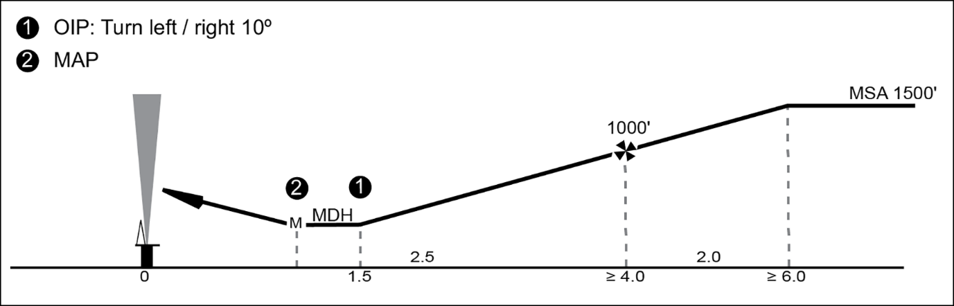
(2)On passing the FAP, the helicopter will descend below the intermediate approach altitude and follow a descent gradient which should not be steeper than 6.5 %. At this stage, vertical separation from the offshore obstacle environment will be lost. However, within the final approach area, the MDA/MDH will provide separation from the surface environment. Descent from 1 000 ft AMSL to 200 ft AMSL at a constant 6.5 % gradient will involve a horizontal distance of 2 nm. In order to follow the guideline that the procedure should not generate an unacceptably high workload for the flight crew, the required actions of levelling off at MDH, changing heading at the offset initiation point (OIP), and turning away at the MAPt, should not be planned to occur at the same time from the destination.
(3)During the final approach, compensation for drift should be applied, and the heading which, if maintained, would take the helicopter directly to the destination should be identified. It follows that at an OIP located at a range of 1.5 nm, a heading change of 10° is likely to result in a track offset of 15° at 1 nm, and the extended centre line of the new track can be expected to have a mean position approximately 300–400 m to one side of the destination structure. The safety margin built into the 0.75-nm decision range (DR) is dependent upon the rate of closure with the destination. Although the airspeed should be in the range of 60–90 KIAS during the final approach, the ground speed, after due allowance for wind velocity, should not be greater than 70 kt.
(g)Missed approach segment
(1)The missed approach segment commences at the MAPt and ends when the helicopter reaches the minimum en route altitude. The missed approach manoeuvre is a ‘turning missed approach’ which should be of not less than 30° and should not, normally, be greater than 45°. A turn away of more than 45° does not reduce the collision risk factor any further nor does it permit a closer DR. However, turns of more than 45° may increase the risk of pilot disorientation, and by inhibiting the rate of climb (especially in the case of an OEI missed approach procedure), may keep the helicopter at an extremely low level for longer than it is desirable.
(2)The missed approach area to be used should be identified and verified as a clear area on the radar screen during the intermediate approach segment. The base of the missed approach area is a sloping surface at 2.5 % gradient starting from MDH at the MAPt. The concept is that a helicopter executing a turning missed approach will be protected by the horizontal boundaries of the missed approach area until vertical separation of more than 130 ft is achieved between the base of the area and the offshore obstacle environment of 500 ft AMSL that prevails outside the area.
(3)A missed approach area, taking the form of a 45° sector orientated left or right of the final approach track, originating from a point 5 nm short of the destination, and terminating on an arc 3 nm beyond the destination, should normally satisfy the specifications of a 30° turning missed approach.
(h)Required visual reference
The visual reference required is that the destination should be in view in order to be able to carry out a safe landing.
(i)Radar equipment
During the ARA procedure, colour mapping radar equipment with a 120° sector scan and a 2.5-nm range scale selected may result in dynamic errors of the following order:
(1)bearing/tracking error of ± 4.5° with 95 % accuracy;
(2)mean ranging error of 250 m; or
(3)random ranging error of ± 250 m with 95 % accuracy.
Figure 1 — Horizontal profile
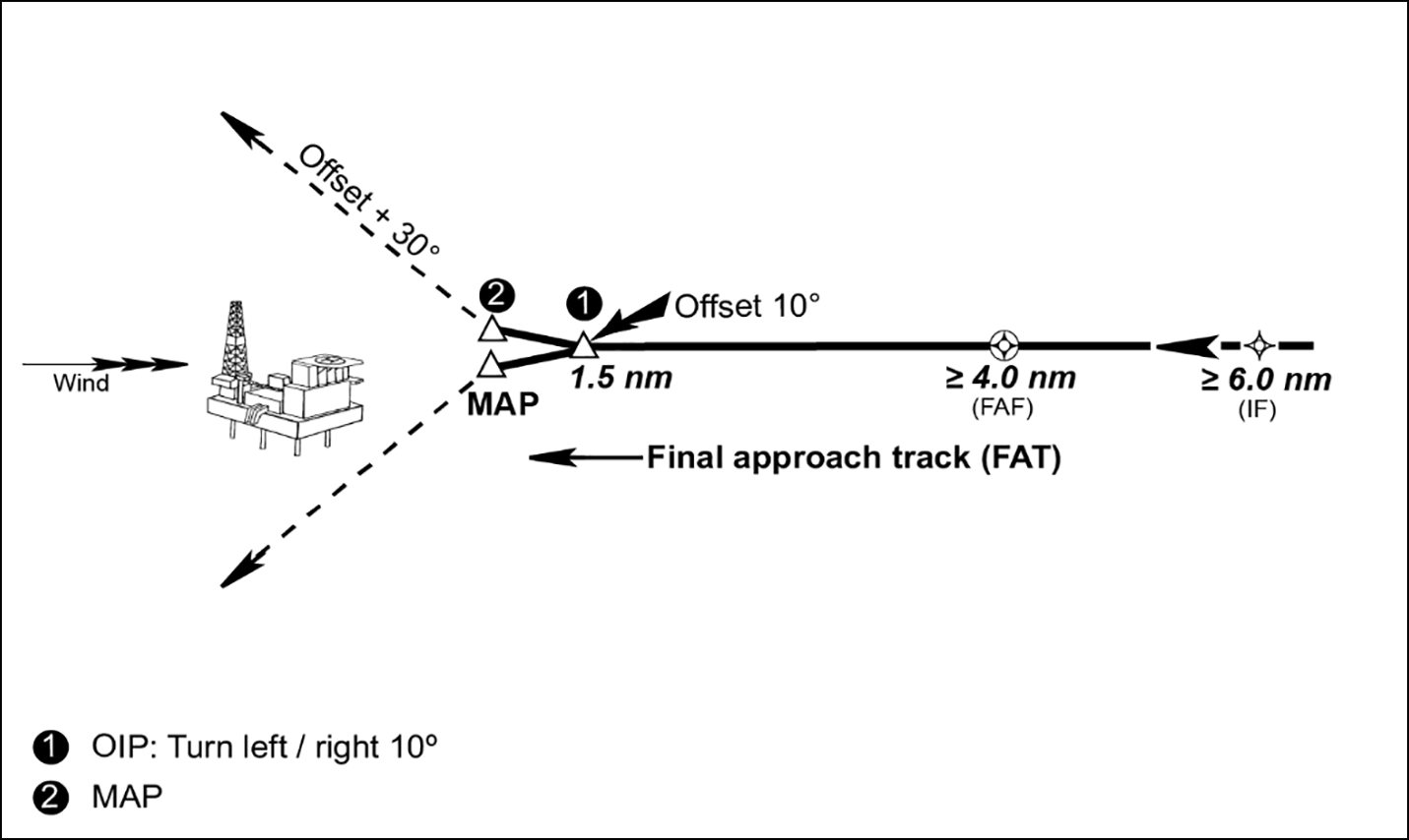
Figure 2 — Vertical profile
GM2 SPA.HOFO.125 Offshore standard approach procedures (OSAPs)
ED Decision 2022/012/R
GLOBAL NAVIGATION SATELLITE SYSTEM (GNSS)/AREA NAVIGATION SYSTEM — AIRBORNE RADAR APPROACH (ARA)
Where an ARA is conducted to a non-moving offshore location (i.e. fixed installation or moored vessel), and the GNSS/area navigation system is used to enhance the safety of the ARA, the following procedure or equivalent should be applied:
(a)selection from the area navigation system database or manual entry of the offshore location;
(b)manual entry of the final approach fix (FAF) or intermediate fix (IF), as a range of and bearing from the offshore location;
(c)the full-scale deviation of the GNSS/area navigation system display should be in accordance with the expected navigation performance, and be no greater than 1 NM;
(d)comparison of weather radar and GNSS range and bearing data to cross-check the position of the offshore location;
(e)use of GNSS guidance to guide the aircraft onto the final approach track during the initial or intermediate approach segments;
(f)use of GNSS guidance from the FAF towards the offset initiation point (OIP) during the final approach segment to establish the helicopter on the correct approach track and, hence, heading;
(g)transition from GNSS guidance to navigation based on headings once the track is stabilised and before reaching OIP;
(h)use of GNSS range of and bearing to the offshore location during the intermediate and final approach segments to cross-check weather radar information (for correct ‘painting’ of the destination and, hence, of other obstacles);
(i)use of GNSS range of the offshore location to enhance confidence in the weather radar determination of arrival at the OIP and MAPt; and
(j)use of GNSS range of and bearing to the destination to monitor separation from the offshore location.
AMC1 SPA.HOFO.125(g) Offshore standard approach procedures (OSAPs)
ED Decision 2022/012/R
TRAINING AND CHECKING FOR OSAPs
(a)Initial training and checking for OSAPs should be conducted either as part of the operator’s conversion course or as a separate equipment and procedure training, and should include all of the following:
(1)ground training, including knowledge of:
(i)the structure of the OSAP;
(ii)the airborne radar specifications, limitations, modes, and usage;
(iii)the area navigation system, as necessary for the envisaged OSAP;
(2)aircraft/FSTD training, including all of the following:
(i)OSAPs to various offshore sites with and without obstacles or obstructions;
(ii)OSAPs in different wind conditions, followed by landings and go-arounds;
(iii)OSAPs in the pilot-monitoring, pilot-flying and single-pilot functions, by day and by night, as relevant to the kind of operations;
(3)LIFUS;
(4)line check.
(b)The recurrent training and checking programme should include at least one OSAP per year in the pilot-monitoring, pilot-flying and single-pilot functions as relevant to the kind of operations. OSAPs should be part of the annual aircraft/FSTD training, the line check or the operator’s proficiency check. Checking is not necessary if training to proficiency is employed.
SPA.HOFO.130 Meteorological conditions
Regulation (EU) 2016/1199
Notwithstanding CAT.OP.MPA.247, NCC.OP.180 and SPO.OP.170, when flying between offshore locations located in class G airspace where the overwater sector is less than 10 NM, VFR flights may be conducted when the limits are at, or better than, the following:
Minima for flying between offshore locations located in class G airspace | ||||
Day | Night | |||
Height* | Visibility | Height* | Visibility | |
Single pilot | 300 feet | 3 km | 500 feet | 5 km |
Two pilots | 300 feet | 2 km** | 500 feet | 5 km*** |
* The cloud base shall allow flight at the specified height to be below and clear of cloud.
** Helicopters may be operated in flight visibility down to 800 m, provided the destination or an intermediate structure is continuously visible.
*** Helicopters may be operated in flight visibility down to 1 500 m, provided the destination or an intermediate structure is continuously visible.
SPA.HOFO.135 Wind limitations for operations to offshore locations
Regulation (EU) 2016/1199
Operation to an offshore location shall only be performed when the wind speed at the helideck is reported to be not more than 60 knots including gusts.
SPA.HOFO.140 Performance requirements at offshore locations
Regulation (EU) 2016/1199
Helicopters taking off from and landing at offshore locations shall be operated in accordance with the performance requirements of the appropriate Annex according to their type of operation.
AMC1 SPA.HOFO.140 Performance requirements – take-off and landing at offshore locations
ED Decision 2016/022/R
FACTORS
To ensure that the necessary factors are taken into account, operators not conducting CAT operations should use take-off and landing procedures that are appropriate to the circumstances and have been developed in accordance with ORO.MLR.100 in order to minimise the risks of collision with obstacles at the individual offshore location under the prevailing conditions.
SPA.HOFO.145 Flight data monitoring (FDM) programme
Regulation (EU) 2016/1199
(a)When conducting CAT operations with a helicopter equipped with a flight data recorder, the operator shall establish and maintain a FDM programme, as part of its integrated management system, by 1 January 2019.
(b)The FDM programme shall be non-punitive and contain adequate safeguards to protect the source(s) of the data.
AMC1 SPA.HOFO.145 Flight data monitoring (FDM) programme
ED Decision 2025/020/R
FDM PROGRAMME
Refer to AMC1 ORO.AOC.130.
[applicable until 31 December 2027 — ED Decision 2021/005/R]
ORGANISATION OF THE FDM PROGRAMME
(a)Safety manager’s responsibilities: refer to point (a) of AMC1 ORO.AOC.130.
(b)Contribution to the management system: refer to point (b) of AMC1 ORO.AOC.130.
(c)FDM analysis techniques: refer to point (c) of AMC1 ORO.AOC.130.
(d)FDM analysis, assessment and process control tools: refer to point (d) of AMC1 ORO.AOC.130.
(e)Safety information and promotion: refer to point (e) of AMC1 ORO.AOC.130.
(f)Accident and incident data requirements: refer to point (f) of AMC1 ORO.AOC.130.
(g)Incident reporting: refer to point (g) of AMC1 ORO.AOC.130.
(h)Data recovery and validation: the data recovery and validation strategy should ensure a sufficiently representative capture of flight information to maintain an overview of operations and that data is recovered from all helicopters that are within the scope of point SPA.HOFO.145. In addition, the validation of FDM events and measurements should be performed sufficiently frequently to enable action to be taken on significant safety issues. Data recovery and validation should incorporate all the points below.
(1)To ensure that a sufficiently representative subset of flights is monitored by the FDM programme, the number of flights available for processing by the FDM programme and that contain valid data should amount to:
(i)at least 60 % of the total number of flights performed in the past 12 months by helicopters that are in the scope of SPA.HOFO.145, if the operator operates fewer than 20 such aircraft; or
(ii)at least 80 % of the total number of flights performed in the past 12 months by helicopters that are in the scope of SPA.HOFO.145, if the operator operates 20 or more such aircraft.
This condition is not applicable to helicopters that performed fewer than 50 flights in the previous 12 months.
(2)To limit the maximum duration during which no flight data may be received from an individual helicopter, the operator should:
(i)have means and procedures to identify a failure of the means to collect data from any individual helicopter that is within the scope of point SPA.HOFO.145 either within 22 calendar days after the failure occurs or before 10 more flights are performed after the failure occurs; and
(ii)correct any failure of the means to collect data from any individual helicopter that is within the scope of point SPA.HOFO.145 within 120 days of being made aware of the failure.
(3)To ensure that significant FDM events (events that correspond to the most significant deviations from the standard operating procedures (SOPs) and circumstances potentially affecting the airworthiness of the aircraft) can be identified without unnecessary delays, the flights for which flight data is collected within the FDM programme (hereafter called ‘collected flights’) should be processed in a timely manner. At least 80 % of the collected flights that were performed in the previous 12 months should have been processed by the FDM software either within 22 calendar days after completion of the collected flight or before 10 flights following the collected flight were performed by the same aircraft.
(4)For each helicopter that is within the scope of point SPA.HOFO.145 and first issued with an individual certificate of airworthiness (CofA) on or after 1 January 2029:
(i)the operator should ensure that, within 90 calendar days after it starts operating the helicopter, the data collected for processing by the FDM software include all the flight parameters required to be recorded by a flight data recorder in accordance with AMC1.2 CAT.IDE.H.190; and
(ii)the operator should verify, within 90 calendar days after it starts operating the helicopter, that the recorded flight parameters specified in point (i) meet the performance specifications (range, sampling intervals, accuracy limits and resolution in read-out) as defined in EUROCAE Document 112A or any later equivalent standard produced by EUROCAE — this verification may be based on the documentation provided by the aircraft manufacturer or the installer of the airborne systems used to collect the flight data.
(5)The operator should explain, upon request by its competent authority, the principles it uses for validating an FDM event, that is, how it determines whether an FDM event genuinely reflects a deviation that is considered abnormal for the flight in which the FDM event occurred.
(6)The operator should validate significant FDM events as a matter of priority. At least 80 % of significant FDM events should be validated within 15 calendar days after their first detection by the FDM software.
(i)Data retention strategy: refer to point (i) of AMC1 ORO.AOC.130.
(j)Data access and security policy: refer to point (j) of AMC1 ORO.AOC.130.
(k)Procedure to prevent disclosure of crew identity: refer to point (k) of AMC1 ORO.AOC.130.
(l)Access to information on flight parameters and FDM algorithms: refer to point (l) of AMC1 ORO.AOC.130.
(m)Airborne systems and equipment: refer to point (m) of AMC1 ORO.AOC.130.
[applicable from 1 January 2028 — ED Decision 2025/020/R]
AMC2 SPA.HOFO.145 Flight data monitoring (FDM) programme
ED Decision 2025/020/R
SCOPE OF THE FLIGHT DATA MONITORING (FDM) PROGRAMME
(a)A set of core FDM events or FDM measurements should be selected to cover, as far as possible, the most significant risks identified by the operator. The definitions of FDM events and FDM measurements in this core set should be designed to help identify deviations from the standard operating procedures (SOPs) that are beyond what is considered normal practice and not only occurrences that require reporting to the competent authority or unscheduled continued airworthiness activity. The definitions of FDM events and measurements in this core set should be continuously reviewed to reflect the operator’s current operating procedures and any newly identified safety risks.
(b)For all helicopters that are within the scope of point SPA.HOFO.145 and first issued with an individual certificate of airworthiness (CofA) on or after 1 January 2016, the FDM programme should monitor, to the extent possible with the available flight data and without requiring overly complex algorithms, precursors of the following key risk areas:
(1)risk of aircraft upset,
(2)risk of collision with terrain,
(3)risk of obstacle collision in flight, during take-off or landing, and
(4)risk of excursion from the touchdown and lift-off area, during take-off or landing.
(c)If the necessary flight parameters are collected by the airborne system used to obtain flight data, the FDM programme should monitor:
(1)exceedances indicating that the airworthiness of the aircraft may be affected and that are related to any of the following parameters:
(i)speed,
(ii)altitude,
(iii)accelerations,
(iv)attitude angles,
(v)aircraft weight,
(vi)engine torque; and
(2)caution and warning alerts to the flight crew, indicating that the airworthiness of the aircraft may be affected.
(d)Upon request by its competent authority, the operator should provide documentation identifying which types of occurrences are monitored with the FDM programme. This documentation should cover at least occurrences subject to mandatory reporting and listed in Commission Implementing Regulation (EU) 2015/1018, Annex I, Section 1 (excluding paragraph 1.5, point (3)) and Section 5. This documentation should include a short description of the applicable FDM event(s) or FDM measurement(s) for each type of occurrence monitored by the FDM programme.
[applicable from 1 January 2028 — ED Decision 2025/020/R]
GM1 SPA.HOFO.145 Flight data monitoring (FDM) programme
ED Decision 2025/020/R
DEFINITION OF AN FDM PROGRAMME
Refer to GM1 ORO.AOC.130, except for the examples that are specific to aeroplane operation.
[applicable until 31 December 2027 — ED Decision 2016/022/R]
IMPLEMENTATION OF AN FDM PROGRAMME
‘Flight data monitoring’ (FDM) is defined in Annex I to this Regulation. It should be noted that the requirement to establish an FDM programme is applicable to all individual aircraft that are within the scope of point SPA.HOFO.145, and not to a subset selected by the operator.
(a)FDM analysis techniques
(1)Exceedance detection / FDM event
(i)FDM programmes are used for detecting what are known as ‘FDM events’, such as deviations from rotorcraft flight manual limits, standard operating procedures (SOPs) or good airmanship. It is advisable to monitor deviations from the SOPs in all phases of flight, including when the aircraft is on the ground.
Examples of FDM events for helicopters: low or high pitch rotation rate on take-off, high pitch attitude on landing, excessive roll attitude, low ground speed on approach.
(ii)Trigger conditions of FDM event algorithms may be as simple as detecting that a ‘redline value’ was exceeded. The majority, however, are composites that define a certain flight phase or configuration. In addition, it might be valuable to define several levels of FDM event severity (such as low, medium and high severity). While such severity levels can help identify significant FDM events and relevant trends, they should not be considered safety risk levels; assessing the safety risk level associated with an occurrence or trend requires a more thorough assessment and consideration of all the relevant data available to the operator.
Example of composite trigger conditions for helicopters: conditions dependent on location or time of day, such as being able to differentiate between day and night operations and/or whether take-off / approach was conducted towards an airfield or an offshore installation.
Examples of significant (high-severity) FDM events for helicopters: high rate of descent below 500 ft, high torque on take-off, terrain awareness warning system ‘PULL UP’ warning, low airspeed on departure.
(iii)FDM events provide useful information, which can complement that provided in crew reports.
Examples for helicopters: engine failure(s), engine / gearbox overtorque, high/low rotor speed, airborne collision avoidance system, stabilisation augmentation system status, system malfunctions.
(iv)The operator may also modify the standard set of core FDM events to account for unique situations it regularly experiences or the SOPs it uses.
Example for helicopters: arrival profiles for helicopter-specific landing areas.
(v)The operator may also define new FDM events to address specific problem areas.
Example for helicopters: to monitor compliance with temporary operating restrictions mandated by an airworthiness directive.
(vi)Being able to easily adjust the variables of FDM event algorithms can be advantageous, as it allows an FDM event definition to be adapted to new operational conditions.
(vii)The choice of appropriate trigger conditions and severity level threshold values for all FDM events is very important for an effective FDM programme. In particular, it is important that the trigger conditions of an FDM event algorithm are set so that it detects not only the most severe deviations (which are subject to mandatory occurrence reporting or require unscheduled inspection or maintenance) but also deviations that are beyond normal piloting practice. This is important for the effective and timely detection of outliers and unsafe trends. It is advisable to document how trigger conditions and severity level threshold values are determined.
(2)All-flight measurements / FDM measurements
FDM data is retained from all flights, not just the ones producing FDM events. A selection of parameters is retained that is sufficient to characterise each flight and enable a comparative analysis of a wide range of operational variability. The distribution of flight parameter values, which can typically be produced with FDM measurements, may contain a wealth of information on common piloting practices and outliers. By analysing such distributions, emerging trends and tendencies may be identified and monitored before the trigger conditions associated with an FDM event are reached.
Examples of parameters monitored for helicopters: maximum torque during take-off, pitch attitude and rotation rates during take-off, gear retraction and extension heights, maximum speed with gear extended.
Examples of comparative analyses for helicopters: pitch attitude, rotation rates achieved during night departures versus day departures.
(3)Statistics
Series of data are collected to support the analysis process: these usually include the number of flights flown per aircraft and details sufficient to generate rate and trend information.
(4)Investigation of incident flight data by the operator
Recorded flight data provides valuable information for follow-up to incident reports and other technical reports. They are useful in adding to the impressions and information recalled by the flight crew. They also provide an accurate indication of system status and performance, which may help in determining cause-and-effect relationships.
Examples of incidents where recorded data could be useful:
—unstable approaches (excessive ground speed, excessive rate of descent, downwind approach, etc.),
—loss of control in flight (incorrect autopilot mode engaged, vortex ring state, etc.),
—exceeding prescribed operating limitations (e.g. related to engine / main gearbox torque, engine temperature, main rotor rpm),
—turbulence encounters or other events causing significant vertical accelerations.
It should be noted that recorded flight data have limitations. For example, not all the information displayed to the flight crew is recorded, the source of recorded data may be different from the source used by a flight instrument, and the sampling rate or the recording resolution of a parameter may be insufficient to capture accurate information.
(5)Continuing airworthiness
Data of FDM measurements and FDM events can be utilised to assist the continuing airworthiness function. For example, engine-monitoring programmes look at measures of engine performance to determine operating efficiency and predict impending failures.
Examples of continuing airworthiness use for helicopters: avionics and other system performance monitoring, gearbox overtorque, engine temperature exceedance.
(b)FDM equipment, FDM software and FDM service
(1)General
FDM programmes generally involve systems that capture flight data, transform the data into an appropriate format for analysis and generate reports and visualisation to assist in assessing the data. Typically, the following are needed for effective FDM programmes:
(i)an on-board device to capture and record data on a wide range of in-flight parameters,
(ii)means to transfer the data recorded on board the aircraft to a secure repository where it can be processed and analysed, and
(iii)software or a service to process and analyse the data, identify deviations from expected performance, generate reports to assist in interpreting the read-outs, etc.
(2)Airborne equipment
Several technical solutions are available, including the following.
(i)Some systems are installed in the aircraft and record flight data onto a removable medium.
(ii)Some systems automatically transmit the recorded data via secure wireless systems after completion of the flight.
(iii)Some systems preprocess the recorded data to be analysed while the aircraft is airborne. Whatever the flight data processing performed by such systems, a complete set of raw flight data still needs to be recovered after the flight, as this is needed for in-depth analysis by the FDM team.
(3)FDM software or service
(i)Processing and analysing flight data require specialised FDM software or a specialised FDM service.
(ii)The FDM software or service typically converts the raw flight data into flight parameters expressed in engineering units and textual interpretation (‘flight parameter decoding’) and applies FDM algorithms to the flight parameters (refer to points (a)(1) and (a)(2)).
(iii)The FDM software or service typically includes the capability to produce parameter plots and parameter tables, the capability to drill down and visualise flight parameter values for the portion of the flight during which an event was detected, access to interpretative material, links to other safety information and statistical presentations.
(iv)For the FDM software or service, the following additional capabilities are advantageous.
(A)In the case of FDM software, the capability to program FDM algorithms, and the capability to interface with advanced processing tools and access advanced functions libraries beyond those offered as part of the FDM software.
(B)The capability to link flight data with other data sources (e.g. occurrence reports or weather data) to facilitate the analysis of events and trends. This capability should be used in accordance with data protection policies and procedures and its output should be restricted to authorised users (refer to AMC1 SPA.HOFO.145).
(C)The capability to export outputs (e.g. FDM event and measurement data) in a standard electronic format that is compatible with business intelligence tools.
(D)The capability to export outputs in formats compatible with geographical information systems.
(E)The capability to replay flight data in a flight animation, thereby facilitating visual reconstruction of an occurrence.
(F)The capability to design and provide individual FDM summary reports or dashboards that can be confidentially consulted by flight crew members. It is more safety-relevant that such reports focus on compliance with the SOPs and aircraft flight manual limits rather than on comparing the performance of an individual pilot with that of their peers.
(G)The capability to export the information related to flight parameter decoding into a file format that:
(a)complies with an electronic documentation standard that has a general public licence policy; and
(b)includes means to retain the history of changes to the decoding information.
An example of an applicable standard is ARINC specification 647A (Flight Recorder Electronic Documentation).
(H)In the case of FDM software, the capability to generate documentation on the flight parameters that are used to produce FDM events and measurements, and the capability to generate documentation describing the logic of the algorithms used to produce FDM events and measurements, and for which type of reportable occurrences these algorithms are relevant.
(v)In case of a change of FDM software or FDM service provider, it is advisable to keep the previous FDM software or service operative for several months to ensure business continuity and validate the outputs of the new FDM software or service.
(c)FDM in practice
(1)FDM process
Typically, operators follow a closed-loop process in applying an FDM programme, for example the following.
(i)Establish a baseline: initially, operators establish a baseline of operational parameters against which changes can be detected and measured. They also determine ranges of flight parameter values that correspond to normal operations, which facilitates the determination of the appropriate trigger conditions for an FDM event definition.
Examples for helicopters: rate of unstable approaches, rate of incorrect pitch rate / pitch attitude at take-off.
(ii)Highlight unusual or potentially unsafe circumstances: the user determines when non-standard, unusual or potentially unsafe circumstances occur; by comparing them with the baseline margins of safety, the changes can be quantified.
Example for helicopters: increases in unstable approaches (or other unsafe events) at particular locations.
(iii)Identify potentially unsafe trends: based on the frequency and severity of FDM events, trends are identified. If a trend shows a significant increase in the frequency and/or severity of FDM events, a safety risk assessment may be necessary, as part of the operator safety risk management. More guidance on the identification of trends can be consulted in the European Operators Flight Data Monitoring forum (EOFDM) document Flight Data Monitoring — Analysis techniques and principles.
Example for helicopters: increases in unstable approaches at particular locations.
(iv)Monitor the effectiveness of corrective actions, if the FDM programme is relevant for that purpose: once a remedial action has been put in place in the framework of the operator’s safety risk management, its effectiveness is monitored, confirming that it has reduced the identified risk and that the risk has not been transferred elsewhere. At this stage, the operator typically evaluates whether the FDM programme can contribute to this monitoring.
Example for helicopters: confirm that the change has resulted in a reduction in events and that no new additional events have been generated.
(v)Adapt the FDM programme to monitor new risks stemming from operational changes.
Example for helicopters: significant changes to the area of operation or business model.
(2)Analysis and follow-up
(i)FDM data is typically processed at short intervals. The data is then reviewed to identify and validate specific FDM events and emerging undesirable trends. Validating an FDM event means determining whether it corresponds to a genuine and abnormal event. It does not include analysing the possible causes or consequences of the event or assessing its safety risks.
(ii)If deviations from the SOPs are detected, motivating an analysis of the causes and circumstances, the information about these deviations is passed (in accordance with point (k) of AMC1 SPA.HOFO.145) to the person responsible for flight crew contact. The decision to initiate flight crew contact (e.g. notification, request for additional information or confidential discussion) should be made after an initial assessment that takes contextual information into account. If a confidential discussion with the flight crew is deemed necessary, the responsible person provides the necessary contact with the pilot in order to clarify the circumstances and obtain feedback for a more thorough safety assessment.
(iii)All FDM events are usually archived in such a way that they can be sorted, validated and presented in easy-to-understand management reports. Over time, these archived data can provide a picture of emerging trends and hazards that would otherwise go unnoticed. In addition, the FDM team may wish to retain samples of de-identified full-flight data for various safety purposes (detailed analysis, training, benchmarking, etc.).
(iv)Sharing safety information is necessary to maintain a competent workforce and support an effective management system (refer to point ORO.GEN.200). Therefore, lessons learnt from the FDM programme may warrant inclusion in the operator’s safety promotion programmes. Safety promotion media may include newsletters, flight safety magazines, emails, video recordings and information on the company’s intranet, highlighting examples in training and simulator exercises. Care is required, however, to ensure that any information acquired through FDM is de-identified before using it in any training or promotional initiative. In addition, it is recommended to not provide individual flight crew members with personalised access to FDM-based information (e.g. individual FDM summary reports or the possibility of replaying one’s flight) without support from an FDM specialist on how to use these systems and correctly interpret the information provided. The safety manager is normally responsible for the transmission of FDM-based information (refer to AMC1 SPA.HOFO.145), which includes defining processes to ensure that such information is validated, clear and relevant to the recipient and provided in accordance with the procedure to prevent disclosure of crew identity.
(v)All successes and failures are recorded, comparing planned programme objectives with expected results. This provides a basis for review of the FDM programme and the foundation for future programme development.
(d)Preconditions for an effective FDM programme
(1)Protection of FDM data and of related crew reports
The integrity of FDM programmes rests upon protection of the FDM data. Any disclosure for purposes other than safety management can compromise the voluntary provision of safety data, thereby compromising flight safety. It is advisable to consider Regulation (EU) 2016/679 (General Data Protection Regulation), where applicable. In addition, the inherent protection of reporters and of persons mentioned in occurrence reports under Regulation (EU) No 376/2014 applies to flight crew members, whether their reports are voluntarily provided or retrospectively requested by the operator after an FDM event. Note that, after an official safety investigation of an accident or serious incident is initiated, the data recorded on a crash-protected flight data recorder should be preserved as part of the investigation data (point CAT.GEN.MPA.195).
(2)Essential trust
The trust established between management and flight crew is the foundation for a successful FDM programme. This trust can be facilitated by:
(i)early participation of the flight crew representatives in the design, implementation and operation of the FDM programme;
(ii)a formal agreement between management and flight crew, identifying the procedures for the use and protection of data; and
(iii)data security, optimised by:
(A)adhering to the agreement;
(B)the operator strictly limiting data access to selected individuals;
(C)maintaining tight control to ensure that identifying data is kept securely; and
(D)ensuring that operational problems are promptly addressed by management.
(3)Requisite safety culture
Indicators of a positive safety culture within an FDM programme typically include:
(i)top management’s demonstrated commitment to promoting a positive safety culture;
(ii)a non-punitive operator policy that covers the FDM programme;
(iii)FDM programme management by dedicated staff under the authority of the safety manager, with a high degree of specialisation and logistical support;
(iv)involvement of persons with appropriate expertise when assessing FDM events, FDM measurements and trends (refer to point (e)(3));
(v)monitoring fleet trends aggregated from numerous operations, not focusing only on specific events;
(vi)a well-structured system to protect the confidentiality of the data; and
(vii)communicating relevant information on the general trends identified by and lessons learnt from the FDM programme in the communications on safety matters specified in AMC1 ORO.GEN.200(a)(4).
(4)Integration with the operator’s management system
Point SPA.HOFO.145 requires the integration of the FDM programme with the operator’s management system. Because of this, FDM programme outputs are expected to be used together with other relevant data sources to support safety risk management (SRM). The SRM process is not an internal process within the FDM programme but part of the operator’s management system. AMC1 SPA.HOFO.145 specifies that the safety manager should be responsible for identifying and assessing issues, which are the first steps of the SRM process. The EOFDM document Breaking the Silos details industry good practices regarding integration of the FDM programme within the management system.
(5)Complete access to flight parameter decoding information
(i)The flight parameter decoding information is the information sufficient for extracting flight parameter values from the recorded data files and decoding them into values expressed in engineering units or textually interpreting them. This information, which is usually provided by the installer of the airborne systems used to collect the flight data, is essential for programming the FDM software to decode the flight parameters.
(ii)Therefore, it is recommended that complete access to the flight parameter decoding information is obtained at the time of aircraft delivery and that unhindered access is maintained. To facilitate the management of this information it is recommended that it is consigned in documentation that complies with an electronic documentation standard and has a general public licence policy. In addition, it is advisable to have a versioning system that allows quick identification of the applicable documentation for any individual aircraft and any time period. Such documentation could be fully or partially generated by the FDM software if the software has this capability.
(iii)When the airborne equipment used for FDM purposes records a copy of the flight data recorder data stream, the flight data recorder decoding documentation that must be retained in accordance with point CAT.GEN.MPA.195 could be used.
(6)Objectives to ensure a good overview of operations
Internal objectives regarding the proportion of collected flights, the time from performing the flight to processing its data with the FDM software or the time to detect that no flight data is being collected any more from an individual helicopter are important to ensure a good overview of operations. It is advisable to set targets that are ambitious enough for this purpose.
Examples of internal targets:
(i)collect data from at least 90 % of the total number of flights performed in the past 12 months by helicopters that are within the scope of point SPA.HOFO.145;
(ii)identify within 10 calendar days a failure of the means to collect data from any individual helicopter that is within the scope of point SPA.HOFO.145;
(iii)process the data of at least 90 % of the collected flights that were performed in the past 12 months within 10 calendar days of the flights’ completion.
(e)Implementing an FDM programme
(1)General considerations
(i)Typically, the following steps are necessary to implement an FDM programme:
(A)implementation of a formal agreement between management and flight crew,
(B)establishment and verification of operational and security procedures,
(C)installation of equipment,
(D)selection and training of dedicated and experienced staff to operate the programme, and
(E)commencement of data analysis and validation.
(ii)An operator with no FDM experience may need a year to achieve an operational FDM programme. Another year may be necessary before any safety and cost benefits appear. Improvements in the analysis software, or the use of outside specialist service providers, may shorten these time frames.
(2)Aims and objectives of an FDM programme
(i)As with any project there is a need to define the direction and objectives of the work. A phased approach is recommended so that the foundations are in place for possible subsequent expansion into other areas. Using a building block approach will allow expansion, diversification and evolution through experience.
Example: with a modular system, begin by looking at basic safety-related issues only.
(ii)A staged set of objectives starting from the first week’s replay and moving through early production reports into regular routine analysis will contribute to a sense of achievement as milestones are met.
Examples of short-term, medium-term and long-term goals:
(A)Short-term goals
—Establish an FDM team (refer to point (e)(3)).
—Establish data download procedures and test FDM software.
—Verify, for all aircraft in the FDM programme, that the flight parameters used for FDM events and measurements are valid and correctly decoded. GM1 CAT.GEN.MPA.195(b) contains guidance on evaluating the validity of flight parameters.
—Verify that the flight parameter decoding information (see point (d)) is complete and correct.
—Design and/or adapt FDM algorithms and test them, and validate and investigate FDM events. For an FDM event algorithm, this includes verifying that the event trigger conditions and the severity level threshold values take into account any applicable aircraft flight manual limit, the SOPs and the distribution of values collected from all operations.
—Establish a user-acceptable routine report format to highlight individual FDM events and facilitate the acquisition of relevant statistics.
(B)Medium-term goals
—Ensure that the FDM programme meets the minimum data recovery and validation objectives and the data retention objectives.
—Produce reports and dashboards that include key performance indicators, in accordance with an established schedule and at a frequency that is sufficient for the proactive handling of safety risks.
—Add other modules to the analysis (e.g. continuing airworthiness).
—Plan for the next fleet to be added to the FDM programme.
(C)Long-term goals
—Network FDM information across all of the operator’s safety information systems.
(iii)Initially, focusing on a few known areas of interest will help prove the system’s effectiveness. In contrast to an undisciplined scattergun approach, a focused approach is more likely to gain early success.
Examples for helicopters: monitoring onshore and offshore approaches and onshore and offshore take-off profiles. Analysis of such known problem areas may generate useful information for the analysis of other areas.
(3)The FDM team
(i)Experience has shown that the team necessary to run an FDM programme could vary in size from one person for a small fleet, to a dedicated section for large fleets. The descriptions below identify various functions to be fulfilled, not all of which need a dedicated position. As the safety manager should be responsible for the FDM programme, and FDM outputs should, as much as possible, be analysed in relation to other safety data sources, the FDM team leader is expected to be part of the safety manager’s team.
(A)Team leader: it is essential that the team leader earns the trust and full support of both management and flight crew. The individual requires good analytical, presentation and management skills.
(B)Flight operations interpreter: this person is usually a qualified pilot (or perhaps a recently retired senior captain or instructor), who knows the operator’s route network and aircraft. This team member’s in-depth knowledge of SOPs, aircraft handling characteristics, aerodromes and routes is used to place the FDM data in a credible context.
(C)Technical interpreter: this person interprets FDM data with respect to the technical aspects of the aircraft operation and is familiar with the information required by the departments in charge of power plant, structures and systems, and with any other engineering monitoring programmes in use by the operator.
(D)Gatekeeper: this person provides the link between the fleet or training managers and flight crew involved in events highlighted by FDM. The position requires good people skills and a positive attitude towards safety education. The person is typically a representative of the flight crew association or an ‘honest broker’ and is the only person permitted to connect the identifying data with the event. It is essential that this person earns the trust of both management and flight crew.
(E)Engineering technical support: this person is usually an avionics specialist. This team member is knowledgeable about FDM and the associated systems needed to run the programme.
(F)FDM analyst: this person is responsible for the design and validation of FDM algorithms and the analysis of FDM outputs. This usually requires at least basic knowledge of statistics; basic programming skills; detailed knowledge of FDM data flows, from the data collection on board the aircraft to the production of FDM-based indicators and dashboards; and in-depth knowledge of the FDM software or service. If the processing of data or the validation of FDM events is subcontracted to a service provider, the FDM analyst should have the necessary skills to effectively control and direct the work performed by that service provider.
(G)FDM administrator: this person is responsible for the day-to-day recovery and processing of the flight data by the FDM software.
(ii)All FDM team members need appropriate training or experience for their respective area of data analysis. Each team member is allocated a realistic amount of time to regularly spend on FDM tasks.
(f)Other uses of flight data
It is recommended to establish a written procedure to prevent the disclosure of crew identity whenever access to flight data or flight-data-based information is requested to meet operational needs, such as fuel use optimisation, aircraft performance and preventive maintenance. As a minimum, it is advisable that such a procedure contains:
(1)the aim of the programme in which flight data or flight-data-based information is to be used;
(2)clear data access and security principles regarding access to flight data and flight-data-based information by staff members and service providers;
(3)data and information retention principles; and
(4)the method to obtain de-identified flight crew feedback on those occasions that require specific flight follow-up for contextual information.
In case a service provider is granted frequent access to flight data, a non-disclosure agreement is also advisable.
(g)The FDM programme and large data exchange programmes
Some States and organisations have set up so-called large data exchange programmes, in which very large amounts of data (including FDM data) provided by many operators and by other industry stakeholders are gathered, centrally processed and analysed. Participation in a large data exchange programme may offer an operator various benefits, such as the ability to compare its safety performance with that of comparable operators or access to other types of data (weather, traffic, etc.) or to advanced data integration capabilities. In addition, if an operator with a small fleet produces small amounts of flight data that do not allow reliable trend identification, joining a large data exchange programme may help to overcome this limitation. However, taking part in a large data exchange programme does not in itself satisfy point ORO.AOC.130, and every operator remains responsible for implementing its FDM programme. In addition, the FDM programme needs to be well integrated into the operator’s management system for it to benefit from a large data exchange programme.
[applicable from 1 January 2028 — ED Decision 2025/020/R]