Filters
GM1 CAT.OP.MPA.303 In-flight check of the landing distance at time of arrival — aeroplanes
ED Decision 2021/005/R
GENERAL
The assessment of the LDTA begins with the acquisition of the latest available weather information and the RCR. The information provided in the RCR is divided in two sections:
(a)The ‘aircraft performance’ section which contains information that is directly relevant in a performance computation.
(b)The ‘situational awareness’ section which contains information that the flight crew should be aware of for a safe operation, but which does not have a direct impact on the performance assessment.
The ‘aircraft performance’ section of the RCR includes a runway condition code (RWYCC), the contaminant type, depth and coverage for each third of the runway.
The determination of the RWYCC is based on the use of the runway condition assessment matrix (RCAM); however, the presentation of the information in the RCAM is appropriate for use by aerodrome personnel trained and competent in assessing the runway condition in a way that is relevant to aircraft performance.
It is the task of the aerodrome personnel to report the appropriate RWYCC in order to allow the flight crew to assess the landing performance characteristics of the runway in use. When no RWYCC is available in winter conditions, the RCAM provides the flight crew with a combination of the relevant information (runway surface conditions: state and/or contaminant or pilot report of braking action (AIREP)) in order to determine the RWYCC.
Table 1 below is an excerpt of the RCAM and permits to carry out the primary assessment based on the reported contaminant type and depth, as well as on the OAT.
Table 1: Association between the runway surface condition and the RWYCC based on the reported contaminant type and depth and on the OAT
Runway surface condition | Surface condition descriptor | Depth | Notes | RWYCC |
Dry | n/a | 6 | ||
Wet | Damp (any visible dampness) | 3 mm or less | Including wet and contaminated runways below 25 % coverage in each runway third | 5 |
Wet | ||||
Slippery wet | 3 | |||
Contaminated | Compacted snow | Any | At or below OAT – 15 °C 3 | 4 |
Above OAT – 15 °C 3 | 3 | |||
Dry snow | 3 mm or less | 5 | ||
More than 3 mm up to 100 mm | Including when any depth occurs on top of compacted snow | 3 | ||
Any | On top of ice | 02 | ||
Frost1 | Any | 5 | ||
Ice | Any | In cold and dry conditions | 1 | |
Slush | 3 mm or less | 5 | ||
More than 3 mm up to 15 mm | 2 | |||
Standing water | 3 mm or less | 5 | ||
More than 3 mm up to 15 mm | 2 | |||
Any | On top of ice | 02 | ||
Wet ice | Any | 02 | ||
Wet snow | 3 mm or less | 5 | ||
More than 3 mm up to 30 mm | Including when any depth occurs on top of compacted snow | 3 | ||
Any | On top of ice | 02 |
Note 1: Under certain conditions, frost may cause the surface to become very slippery.
Note 2: Operations in conditions where less-than-poor braking action prevails are prohibited.
Note 3: The runway surface temperature should preferably be used where available.
A primary assessment may have to be downgraded by the aerodrome operator based on an AIREP of lower braking action than the one typically associated with the type and depth of contaminant on the runway or any other observation.
Upgrading a RWYCC 5, 4, 3 or 2 determined by the aerodrome operator from the observed contaminant type is not allowed.
A RWYCC 1 or 0 maybe be upgraded by the aerodrome operator to a maximum of RWYCC 3. The reason for the upgrade will be specified in the ‘situational awareness’ section of the RCR.
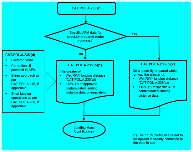
When the aerodrome operator is approved for operations on specially prepared winter runways, in accordance with Annex V (Part-ADR.OPS) to Regulation (EU) No 139/2014, the RWYCC of a runway that is contaminated with compacted snow or ice, may be reported as RWYCC 4 depending upon a specific treatment of the runway. In such cases, the reason for the upgrade will be specified in the ‘situational awareness’ section of the RCR. When the aerodrome operator is approved for specially prepared winter runways, in accordance with Annex IV (Part-ADR.OPS) to Regulation (EU) No 139/2014, a runway that is contaminated with compacted snow or ice and has been treated according to specific procedures, will normally be reported as a maximum of RWYCC 4 SPECIALLY PREPARED WINTER RUNWAY. If the aerodrome operator is in doubt about the quality of the surface, it will be reported with a lower RWYCC, but the runway descriptor will still be SPECIALLY PREPARED WINTER RUNWAY. The term DOWNGRADED will be used in the ‘situational awareness’ section of the RCR. A SPECIALLY PREPARED WINTER RUNWAY has no loose contaminant; hence no contaminant drag on acceleration, and stopping performance corresponding to the reported RWYCC.
Performance information for the assessment of the LDTA correlates the aircraft performance with the RWYCC contained in the RCR, hence the calculation will be based on the RWYCC of the intended runway of landing.
GM2 CAT.OP.MPA.303 In-flight check of the landing distance at time of arrival — aeroplanes
ED Decision 2021/005/R
RUNWAY CONDITION CONSIDERATIONS
When available for the portion of the runway that will be used for landing, the following elements are relevant for consideration:
(a)RWYCC;
(b)expected runway conditions (contaminant type and depth);
(c)other information contained in the RCR related to the following elements:
(1)width of the runway to which the RWYCC applies if less than the published runway width;
(2)reduced runway length;
(3)drifting snow on the runway;
(4)loose sand on the runway;
(5)chemical treatment on the runway;
(6)snowbanks on the runway;
(7)snowbanks on taxiways;
(8)snowbanks adjacent to the runway;
(9)taxiway conditions;
(10)apron conditions;
(11)State approved and published use of measured friction coefficient;
(12)plain language remarks;
(d)AIREP of braking action.
AIRCRAFT PERFORMANCE CONSIDERATIONS
The following elements may impact landing distance calculations:
(a)runway slope;
(b)aerodrome elevation;
(c)wind;
(d)temperature;
(e)aeroplane mass and configuration;
(f)approach speed at threshold;
(g)eventual adjustments to the landing distance, such as autoland; and
(h)planned use of available and operative aeroplane ground deceleration devices.
AUTOBRAKE USAGE
While autobrakes are a part of the aeroplane’s landing configuration, the landing distance assessment at the time of arrival is not intended to force a higher-than-necessary autobrake selection. For operations where the RWYCC is 6 or 5, if the manual braking distance provides at least 15 % safety margin, then the braking technique may include a combination of autobrakes and manual braking even if the selected autobrake landing data does not provide a 15 % safety margin.
GENERAL
Background information and further guidance on the in-flight check of the LDTA may be found in ICAO Doc 10064 ‘Aeroplane Performance Manual’.
GM3 CAT.OP.MPA.303 In-flight check of the landing distance at time of arrival — aeroplanes
ED Decision 2021/005/R
RCR, RWYCC AND RCAM
A detailed description of the RCR format and content, the RWYCC and the RCAM may be found in Annex V (Part-ADR.OPS) to Regulation (EU) No 139/2014. Further guidance may be found in the following documents:
(a)ICAO Doc 9981 ‘PANS Aerodromes’;
(b)ICAO Doc 4444 ‘PANS ATM’;
(c)ICAO Doc 10064 ‘Aeroplane Performance Manual’; and
(d)ICAO Circular 355 ‘Assessment, Measurement and Reporting of Runway Surface Conditions’.
AMC1 CAT.OP.MPA.303(e) In-flight check of the landing distance at time of arrival — aeroplanes
ED Decision 2021/005/R
PERFORMANCE INFORMATION FOR THE ASSESSMENT OF THE LDTA — APPROVED DATA
Approved data for the assessment of the LDTA contained in the AFM should be developed in accordance with AMC 25.1592, or equivalent.
PERFORMANCE INFORMATION FOR THE ASSESSMENT OF THE LDTA — SUPPLEMENTARY DATA
When approved data for the assessment of the LDTA contained in the AFM is insufficient, the content of the AFM should be supplemented with one of the following sets of data, provided by the aircraft manufacturer or the type certificate holder (TCH) or an organisation approved under Part 21 and having the relevant privileges within the scope of its organisation approval:
(a)Data for the assessment of the LDTA produced for aeroplanes not having CS 25.1592 or equivalent in their certification basis. Such data may be presented in terms of runway surface conditions, pilot-reported braking actions, or both, and should include at least:
(1)an operational airborne distance;
(2)the range of braking actions as related to the RWYCC;
(3)the effect of speed increments over threshold;
(4)the effect of temperature; and
(5)the effect of runway slope.
When data is provided only in terms of pilot-reported braking actions, instructions should be provided on how to use such data to carry out an assessment of the LDTA in terms of a runway surface condition description.
(b)Data developed in accordance with FAA AC 25-32.
(c)Data for wet runways corrected to meet the criteria of LDTA, as listed under point (a), in accordance with a methodology provided by the aircraft manufacturer or the type certificate holder (TCH) or an organisation approved under Part 21 and having the relevant privileges in the scope of its organisation approval.
(d)Data for contaminated runways developed in compliance with CS 25.1591 or equivalent, which were in use before the implementation of the LDTA, and are corrected to meet the criteria of the LDTA, as listed under point (a), in accordance with a methodology provided by the aircraft manufacturer or the TCH or an organisation approved under Part 21 and having the relevant privileges within the scope of its organisation approval.
PERFORMANCE INFORMATION FOR THE ASSESSMENT OF THE LDTA — DATA DETERMINED BY EASA
When there is no data available for the assessment of the LDTA, performance information for the assessment of the LDTA may be determined by applying the following method:
(a)Correction factors may be applied to the certified landing distances on dry runway published in the AFM for turbojet-powered aeroplanes and turbopropeller-powered aeroplanes.
(b)For this purpose, the landing distance factors (LDFs) from Table 1 below may be used:
Table 1: LDFs
Runway condition code (RWYCC) | 6 | 5 | 4 | 3 | 2 | 1 |
Runway descriptors | Note 1 | Note 1 | Note 1 | Note 1 | Note 1 | Note 1 |
Turbojet without reverse | 1.67 | 2.6 | 2.8 | 3.2 | 4.0 | 5.1 |
Turbojet with all reversers operating | 1.67 | 2.2 | 2.3 | 2.5 | 2.9 | 3.4 |
Turboprop (see Note 2) | 1.67 | 2.0 | 2.2 | 2.4 | 2.7 | 2.9 |
Note 1: Runway descriptors may be found in the RCAM for each RWYCC or braking action.
Note 2: These LDFs apply only to modern turboprops with efficient disking drag. For older turboprops without adequate disking drag, use the LDFs for turbojet without reverse.
Note 3: The LDFs can apply to any type of anti-skid system, i.e. fully-modulating, quasi-modulating or on-off system.
(1)To find the LDTA, multiply the AFM (dry, unfactored) landing distance by the applicable LDFs from Table 1 above for the runway conditions existing at the time of arrival. If the AFM landing distances are presented as factored landing distances, then that data needs to be adjusted to remove the applicable dispatch factors applied to that data before the LDFs from Table 1 above are applied.
Note 1: Dispatch factors that are sometimes applied in AFMs to landing distances in order to provide factored distances to operators are not intended to be cumulated with the LDFs for the calculation of the LDTA.
(2)The LDFs given in Table 1 above include a 15 % safety margin and an air distance representative of normal operational practices. They account for variations of temperature up to international standard atmosphere (ISA) + 20 °C, runway slopes between –2 % and +2 %, and an average approach speed increment of 5 up to 20 kt. They may not be conservative for all configurations in case of unfavourable combinations of these parameters.
CAT.OP.MPA.305 Commencement and continuation of approach
Regulation (EU) 2021/2237
(a)For aeroplanes, if the reported visibility (VIS) or controlling RVR for the runway to be used for landing is less than the applicable minimum, then an instrument approach operation shall not be continued:
(1)past a point at which the aeroplane is 1 000 ft above the aerodrome elevation; or
(2)into the final approach segment (FAS) if the DH or MDH is higher than 1 000 ft.
(b)For helicopters, if the reported RVR is less than 550 m and the controlling RVR for the runway to be used for landing is less than the applicable minimum, then an instrument approach operation shall not be continued:
(1)past a point at which the helicopter is 1 000 ft above the aerodrome elevation; or
(2)into the FAS if the DH or MDH is higher than 1 000 ft.
(c)If the required visual reference is not established, then a missed approach shall be executed at or before the DA/H or the MDA/H.
(d)If the required visual reference is not maintained after DA/H or MDA/H, then a go-around shall be executed promptly.
(e)Notwithstanding point (a), in the case where no RVR is reported, and the reported VIS is less than the applicable minimum, but the converted meteorological visibility (CMV) is equal or greater than the applicable minimum, then the instrument approach can be continued to the DA/H or MDA/H.
GM1 CAT.OP.MPA.305 Commencement and continuation of approach
ED Decision 2023/007/R
APPLICATION OF RVR OR VIS REPORTS — AEROPLANES
(a)There is no prohibition on the commencement of an approach based on the reported RVR or VIS. The restriction in CAT.OP.MPA.305 applies only if the RVR or VIS is reported and applies to the continuation of the approach past a point where the aircraft is 1 000 ft above the aerodrome elevation or in the FAS, as applicable.
APPLICATION OF RVR OR VIS REPORTS — HELICOPTERS
(b)There is no prohibition on the commencement of an approach based on the reported RVR. The restriction in CAT.OP.MPA.305 applies to the continuation of the approach past a point where the aircraft is 1 000 ft above the aerodrome elevation or in the final approach segment as applicable.
The prohibition to continue the approach applies only if the RVR is reported and it is below 550 m and below the operating minima. There is no prohibition based on VIS.
(c)If the reported RVR is 550 m or greater, but it is less than the RVR calculated in accordance with AMC5 CAT.OP.MPA.110, a go-around is likely to be necessary since visual reference may not be established at the DH or MDH. Similarly, in the absence of an RVR report, the reported visibility or a digital image may indicate that a go-around is likely. The commander should consider the available options, based on a thorough assessment of risk, such as diverting to an alternate, before commencing the approach.
APPLICATION OF RVR OR VIS REPORTS — ALL AIRCRAFT
(d)If a deterioration in the RVR or VIS is reported once the aircraft is below 1 000 ft or in the FAS, as applicable, then there is no requirement for the approach to be discontinued. In this situation, the normal visual reference requirements would apply at the DA/H.
(e)Where additional RVR information is provided (e.g. midpoint and stop end), this is advisory; such information may be useful to the pilot in order to determine whether there will be sufficient visual reference to control the aircraft during roll-out and taxi. For operations where the aircraft is controlled manually during roll-out, Table 1 (aeroplanes) in AMC1 SPA.LVO.100(a) and Table 3 (helicopters) in AMC2 SPA.LVO.100(a) provide an indication of the RVR (e.g. midpoint and stop end) that may be required to allow manual lateral control of the aircraft on the runway.
AMC1 CAT.OP.MPA.305(a) Commencement and continuation of approach
ED Decision 2022/012/R
MINIMUM RVR FOR CONTINUATION OF APPROACH — AEROPLANES
(a)The touchdown RVR should be the controlling RVR.
(b)If the touchdown RVR is not reported, then the midpoint RVR should be the controlling RVR.
(c)Where the RVR is not available, CMV should be used except for the purpose of continuation of an approach in LVO in accordance with AMC10 CAT.OP.MPA.110.
AMC1 CAT.OP.MPA.305(b) Commencement and continuation of approach
ED Decision 2022/012/R
MINIMUM RVR FOR CONTINUATION OF APPROACH — HELICOPTERS
(a)The touchdown RVR should be the controlling RVR.
(b)If the touchdown RVR is not reported, then the midpoint RVR should be the controlling RVR.
AMC1 CAT.OP.MPA.305(c) Commencement and continuation of approach
ED Decision 2022/012/R
VISUAL REFERENCES FOR INSTRUMENT APPROACH OPERATIONS
For instrument approach operations Type A and CAT I instrument approach operations Type B, at least one of the visual references specified below should be distinctly visible and identifiable to the pilot at the MDA/H or the DA/H:
(a)elements of the approach lighting system;
(b)the threshold;
(c)the threshold markings;
(d)the threshold lights;
(e)the threshold identification lights;
(f)the visual glide path indicator;
(g)the TDZ or TDZ markings;
(h)the TDZ lights;
(i)the FATO/runway edge lights; or
(j)for helicopter PinS approaches, the identification beacon light and visual ground reference;
(k)for helicopter PinS approaches, the identifiable elements of the environment defined on the instrument chart;
(l)for helicopter PinS approaches with instructions to ‘proceed VFR’, sufficient visual cues to determine that VFR criteria are met; or
(m)other visual references specified in the operations manual.
CAT.OP.MPA.310 Operating procedures — threshold crossing height — aeroplanes
Regulation (EU) 2021/2237
The operator shall establish operational procedures designed to ensure that an aeroplane conducting 3D instrument approach operations crosses the threshold of the runway by a safe margin, with the aeroplane in the landing configuration and attitude.
CAT.OP.MPA.311 Reporting on runway braking action
Regulation (EU) 2020/1176
Whenever the runway braking action encountered during the landing roll is not as good as that reported by the aerodrome operator in the runway condition report (RCR), the commander shall notify the air traffic services (ATS) by means of a special air-report (AIREP) as soon as practicable.
AMC1 CAT.OP.MPA.311 Reporting on runway braking action
ED Decision 2021/005/R
GENERAL
Since both the ATC and the aerodrome operator rely on accurate braking action reports, flight crew should use standardised terminology in accordance with ICAO Doc 4444 ‘PANS ATM’.
The following Table 1 shows the correlation between the terminology to be used in the AIREP to report the braking action and the RWYCC.
Table 1: Association between AIREP and RWYCC
AIREP (braking action) | Description | RWYCC |
N/A | 6 | |
GOOD | Braking deceleration is normal for the wheel braking effort applied AND directional control is normal. | 5 |
GOOD TO MEDIUM | Braking deceleration OR directional control is between good and medium. | 4 |
MEDIUM | Braking deceleration is noticeably reduced for the wheel braking effort applied OR directional control is noticeably reduced. | 3 |
MEDIUM TO POOR | Braking deceleration OR directional control is between medium and poor. | 2 |
POOR | Braking deceleration is significantly reduced for the wheel braking effort applied OR directional control is significantly reduced. | 1 |
LESS THAN POOR | Braking deceleration is minimal to non-existent for the wheel braking effort applied OR directional control is uncertain. | 0 |
An AIREP should be transmitted to the ATC, in accordance with one of the following specifications, as applicable:
(a)Good braking action is reported as ‘BRAKING ACTION GOOD’.
(b)Good to medium braking action is reported as ‘BRAKING ACTION GOOD TO MEDIUM’.
(c)Medium braking action is reported as ‘BRAKING ACTION MEDIUM’.
(d)Medium to poor braking action is reported as ‘BRAKING ACTION MEDIUM TO POOR’.
(e)Poor braking action is reported as ‘BRAKING ACTION POOR’.
(f)Less than poor braking action is reported as ‘BRAKING ACTION LESS THAN POOR’.
In some cases, the differences between two consecutive levels of the six braking action categories between ‘Good’ and ‘Less than Poor’ may be too subtle for the flight crew to detect. It is therefore acceptable for the flight crew to report on a more coarse scale of ‘Good’, ‘Medium’ and ‘Poor’.
Whenever requested by ATC, or if the braking action encountered during the landing roll is not as previously reported by the aerodrome operator in the RCR, pilots should provide a braking action report. This is especially important and safety relevant where the experienced braking action is worse than the braking action associated with any RWYCC code currently in effect for the portion of the runway concerned.
When the braking action experienced during landing is better than that reported by the aerodrome operator, it is also relevant to report this information, which may trigger further actions for the aerodrome operator in order to update the RCR.
If an aircraft-generated braking action report is available, it should be transmitted, identifying its origin accordingly. If the flight crew have a reason to modify the aircraft-generated braking action report based on their judgement, the commander should be able to amend such report.
A braking action AIREP of ‘Less than Poor’ leads to a runway closure until the aerodrome operator can improve the runway condition.
An air safety report should be submitted whenever flight safety has been endangered due to low braking action.
GM1 CAT.OP.MPA.311 Reporting on runway braking action
ED Decision 2021/005/R
GENERAL
The role of the flight crew in the runway surface condition reporting process does not end once a safe landing has been achieved. While the aerodrome operator is responsible for generating the RCR, flight crew are responsible for providing accurate braking action reports.
The flight crew braking action reports provide feedback to the aerodrome operator regarding the accuracy of the RCR resulting from the observed runway surface conditions.
ATC passes these braking action reports to the aerodrome operator, which in turn uses them in conjunction with the RCAM to determine if it is necessary to downgrade or upgrade the RWYCC.
During busy times, runway inspections and maintenance may be less frequent and need to be sequenced with arrivals. Therefore, aerodrome operators may depend on braking action reports to confirm that the runway surface condition is not deviating significantly from the published RCR.
AMC1 CAT.OP.MPA.303 & CAT.OP.MPA.311 In-flight check of the landing distance at time of arrival — aeroplanes & Reporting on runway braking action
ED Decision 2021/005/R
FLIGHT CREW TRAINING
Flight crew members should be trained on the use of the RCR, on the use of performance data for the assessment of the LDTA and on reporting braking action using the AIREP format.
GM1 CAT.OP.MPA.303 & CAT.OP.MPA.311 In-flight check of the landing distance at time of arrival — aeroplanes & Reporting on runway braking action
ED Decision 2021/005/R
SYLLABUS
A training syllabus should include, in addition to the requirements of Subpart FC of Annex III (ORO.FC), at least the following elements:
(a)General
(1)Contamination
(i)Definition
(ii)Contaminants which cause increased drag thus affecting acceleration, and contaminants which cause reduced braking action affecting deceleration
(iii)Slippery when wet condition
(2)Contaminated runway
(i)Runway surface condition descriptors
(ii)Operational observations with friction devices
(iii)Operator´s policy on the usage of:
A.reduced take-off thrust
B.reports by runway thirds
(iv)Stopway
(3)Runway condition codes
(i)RCAM
A.Differences between those published for aerodromes and flight crew
B.Format in use
C.The use of runway friction measurements
D.The use of temperature
E.RWYCC
F.Downgrade/upgrade criteria
G.Difference between a calculation and an assessment
(ii)Braking action
(iii)Use of aircraft wind limit diagram with contamination
(4)Runway condition report
(i)Availability
(ii)Validity
(iii)Performance and situational awareness
(iv)Decoding
(v)Promulgation and reception
(5)Aeroplane control in take-off and landing
(i)Lateral control
A.Windsock effect
B.Effect of reversers
C.Cornering forces
D.Crosswind limitations (including operations when the cleared runway width is less than published
(ii)Longitudinal control
A.V1 correction in correlation with minimum control speed on ground
B.Aquaplaning
C.Anti-skid
D.Autobrake
(6)Take-off distance
(i)Acceleration and deceleration
(ii)Take-off performance limitations
(iii)Take-off distance models
(iv)Factors affecting TO distance
(v)Why to use the type and depth of contaminant instead of the RWYCC
(vi)Safety margins
(7)Landing distance
(i)Distance at time of arrival model
(ii)Factors affecting landing distance
(iii)Safety margins
(8)Exceptions
(i)States that do not comply with ICAO standards for RCR and assessment of the LDTA
(b)Flight planning
(1)Dispatch/in-flight conditions
(2)MEL/CDL items affecting take-off and landing performance
(3)Operator´s policy on variable wind and gusts
(4)Landing performance at destination and alternates
(i)Selection of alternates if an aerodrome is not available
A.En-route alternates
B.Destination alternates
(ii)Number of alternates
(iii)Runway condition
(c)Take-off
(1)Runway selection
(2)Take-off from a wet or contaminated runway
(d)In-flight
(1)Landing distance
(i)Distance at time of arrival calculations
A.Considerations for flight crew
B.Operator´s policy
(ii)Factors affecting landing distance
(iii)Runway selection for landing
(iv)Safety margins
(2)Use of aircraft systems
(i)Brakes/autobrakes
(ii)Difference between friction limited braking and different modes of autobrakes
(iii)Reversers
(e)Landing techniques
(1)Flight crew procedures and flying techniques when landing on length limited runway
(f)Safety considerations
(1)Types of errors possible
(2)Mindfulness principles to avoid biases that may lead to errors
(g)Documentation and records
(h)AIREPs
(1)Assessment of braking action
(2)Terminology
(3)Automated/aircraft-generated braking action reports, if applicable
(4)Air safety reports, if flight safety has been endangered due to insufficient braking action
CAT.OP.MPA.312 EFVS 200 operations
Regulation (EU) 2021/2237
(a)An operator that intends to conduct EFVS 200 operations shall ensure that:
(1)the aircraft is certified for the intended operations;
(2)only runways, FATO and instrument approach procedures (IAPs) suitable for EFVS operations are used;
(3)the flight crew members are competent to conduct the intended operation, and a training and checking programme for the flight crew members and relevant personnel involved in the flight preparation is established;
(4)operating procedures are established;
(5)any relevant information is documented in the minimum equipment list (MEL);
(6)any relevant information is documented in the maintenance programme;
(7)safety assessments are carried out and performance indicators are established to monitor the level of safety of the operation; and
(8)the aerodrome operating minima take into account the capability of the system used.
(b)The operator shall not conduct EFVS 200 operations when conducting LVOs.
(c)Notwithstanding point (a)(1), the operator may use EVSs meeting the minimum criteria to conduct EFVS 200 operations, provided that this is approved by the competent authority.
GM1 CAT.OP.MPA.312 EFVS 200 operations
ED Decision 2022/012/R
GENERAL
(a)EFVS operations exploit the improved visibility provided by the EFVS to extend the visual segment of an instrument approach. EFVSs cannot be used to extend the instrument segment of an approach and thus the DH for EFVS 200 operations is always the same as for the same approach conducted without EFVS.
(b)Equipment for EFVS 200 operations
(1)In order to conduct EFVS 200 operations, a certified EFVS is used (EFVS-A or EFVS-L). An EFVS is an enhanced vision system (EVS) that also incorporates a flight guidance system and displays the image on a head-up display (HUD) or equivalent display. The flight guidance system will incorporate aircraft flight information and flight symbology.
(2)In multi-pilot operations, a suitable display of EFVS sensory imagery is provided to the pilot monitoring.
(c)Suitable approach procedures
(1)Types of approach operation are specified in AMC1 CAT.OP.MPA.312(a)(2)
EFVS 200 operations should be conducted as 3D approach operations. This may include operations based on NPA procedures, approach procedures with vertical guidance and precision approach procedures including approach operations requiring specific approvals, provided that the operator holds the necessary approvals.
(2)Offset approaches
Refer to AMC1 CAT.OP.MPA.312(a)(2).
(3)Circling approaches
EFVSs incorporate a HUD or an equivalent system so that the EFVS image of the scene ahead of the aircraft is visible in the pilot’s forward external FOV. Circling operations require the pilot to maintain visual references that may not be directly ahead of the aircraft and may not be aligned with the current flight path. EFVSs cannot therefore be used in place of natural visual reference for circling approaches.
(d)Aerodrome operating minima for EFVS 200 operations determined in accordance with AMC1 CAT.OP.MPA.312(a)(8)
The performance of EFVSs depends on the technology used and weather conditions encountered. Table 1 ‘Operations utilising EFVS: RVR reduction’ has been developed after an operational evaluation of two different EVSs both using infrared sensors, along with data and support provided by the FAA. Approaches were flown in a variety of conditions including fog, rain and snow showers, as well as at night to aerodromes located in mountainous terrain. Table 1 contains conservative figures to cater for the expected performance of infrared sensors in the variety of conditions that might be encountered. Some systems may have better capability than those used for the evaluation, but credit cannot be taken for such performance in EFVS 200 operations.
(e)The conditions for commencement and continuation of the approach in accordance with CAT.OP.MPA.305
Pilots conducting EFVS 200 operations may commence an approach and continue that approach below 1 000 ft above the aerodrome or into the FAS if the reported RVR or CMV is equal to or greater than the lowest RVR minima determined in accordance with AMC1 CAT.OP.MPA.312(a)(8) and if all the conditions for the conduct of EFVS 200 operations are met.
Should any equipment required for EFVS 200 operations be unserviceable or unavailable, the conditions to conduct EFVS 200 operations would not be satisfied, and the approach should not be commenced. In the event of failure of the equipment required for EFVS 200 operations after the aircraft descends below 1 000 ft above the aerodrome or into the FAS, the conditions of CAT.OP.MPA.305 would no longer be satisfied unless the RVR reported prior to commencement of the approach was sufficient for the approach to be flown without EFVS in lieu of natural vision.
(f)EFVS image requirements at the DA/H specified in AMC1 CAT.OP.MPA.312(a)(4)
The requirements for features to be identifiable on the EFVS image in order to continue the approach below the DH are more stringent than the visual reference requirements for the same approach flown without EFVS. The more stringent standard is needed because the EFVS might not display the colour of lights used to identify specific portions of the runway and might not consistently display the runway markings. Any visual approach path indicator using colourcoded lights may be unusable.
(g)Obstacle clearance in the visual segment
The ‘visual segment’ is the portion of the approach between the DH or the MAPt and the runway threshold. In the case of EFVS 200 operations, this part of the approach may be flown using the EFVS image as the primary reference and obstacles may not always be identifiable on an EFVS image. The operational assessment specified in AMC1 CAT.OP.MPA.312(a)(2) is therefore required to ensure obstacle clearance during the visual segment.
(h)Visual reference requirements at 200 ft above the threshold
For EFVS 200 operations, natural visual reference is required by a height of 200 ft above the runway threshold. The objective of this requirement is to ensure that the pilot will have sufficient visual reference to land. The visual reference should be the same as that required for the same approach flown without EFVS.
Some EFVSs may have additional requirements that have to be fulfilled at this height to allow the approach to continue, such as a requirement to check that elements of the EFVS display remain correctly aligned and scaled to the external view. Any such requirements will be detailed in the AFM and included in the operator’s procedures.
(i)Specific approval for EFVS
In order to use an EFVS without natural visual reference below 200 ft above the threshold, the operator needs to hold a specific approval in accordance with Part-SPA.
(j)Go-around
A go-around will be promptly executed if the required visual references are not maintained on the EFVS image at any time after the aircraft has descended below the DA/H or if the required visual references are not distinctly visible and identifiable using natural vision after the aircraft is below 200 ft. It is considered more likely that an EFVS 200 operation could result in the initiation of a go-around below DA/H than the equivalent approach flown without EFVS, and thus the operational assessment required by AMC1 CAT.OP.MPA.312(a)(2) takes into account the possibility of a balked landing.
An obstacle free zone (OFZ) may be provided for CAT I precision approach procedures. Where an OFZ is not provided for a CAT I precision approach, this will be indicated on the approach chart. NPA procedures and approach procedures with vertical guidance (APV) provide obstacle clearance for the missed approach based on the assumption that a go-around is executed at the MAPt and not below the OCH.
AMC1 CAT.OP.MPA.312(a)(1) EFVS 200 operations
ED Decision 2022/012/R
EQUIPMENT CERTIFICATION
For EFVS 200 operations, the aircraft should be equipped with an approach system using EFVS-A or a landing system using EFVS-L.
AMC1 CAT.OP.MPA.312(a)(2) EFVS 200 operations
ED Decision 2022/012/R
AERODROMES AND INSTRUMENT PROCEDURES SUITABLE FOR EFVS 200 OPERATIONS
(a)For EFVS 200 operations, the operator should verify the suitability of a runway before authorising EFVS operations to that runway through an operational assessment taking into account the following elements:
(1)the obstacle situation;
(2)the type of aerodrome lighting;
(3)the available IAPs;
(4)the aerodrome operating minima; and
(5)any non-standard conditions that may affect the operations.
(b)EFVS 200 operations should only be conducted as 3D operations, using an IAP in which the final approach track is offset by a maximum of 3 degrees from the extended centre line of the runway.
(c)The IAP should be designed in accordance with PANS-OPS, Volume I (ICAO Doc 8168) or equivalent criteria.
AMC2 CAT.OP.MPA.312(a)(2) EFVS 200 operations
ED Decision 2022/014/R
VERIFICATION OF THE SUITABILITY OF RUNWAYS FOR EFVS 200 OPERATIONS
The operational assessment before authorising the use of a runway for EFVS 200 operations should be conducted as follows:
(a)Check whether the runway has been promulgated as suitable for EFVS operations or is certified as a precision approach runway category II or III by the State of the aerodrome. If this is so, then check whether and where the approach and runway lights installed (notably incandescent or LED lights) are adequate for the EFVS equipment used by the operator.
(b)If the check in point (a) above comes out negative (the runway is not promulgated as EFVS suitable or is not category II or III), then proceed as follows:
(1)For straight-in IAPs, US Standard for Terminal Instrument Procedures (TERPS)81 may be considered to be acceptable as an equivalent to PANS-OPS. If other design criteria than those in PANS-OPS or US TERPS are used, the operations should not be conducted.
(2)If an OFZ is established, this will ensure adequate obstacle protection from 960 m before the threshold. If an OFZ is not established or if the DH for the approach is above 250 ft, then check whether there is a visual segment surface (VSS).
(3)VSSs are required for procedures published after 15 March 2007, but the existence of the VSS has to be verified through the aeronautical information publication (AIP), operations manual Part C, or direct contact with the aerodrome. Where the VSS is established, it may not be penetrated by obstacles. If the VSS is not established or is penetrated by obstacles and an OFZ is not established, then the operations should not be conducted. Note: obstacles of a height of less than 50 ft above the threshold may be disregarded when assessing the VSS.
(4)Runways with obstacles that require visual identification and avoidance should not be accepted.
(5)For the obstacle protection of a balked landing where an OFZ is not established, the operator may specify that pilots follow a departure procedure in the event of a balked landing, in which case it is necessary to verify that the aircraft will be able to comply with the climb gradients published for the instrument departure procedures for the expected landing conditions.
(6)Perform an assessment of the suitability of the runway which should include whether the approach and runway lights installed (notably incandescent or LED lights) are adequate for the EFVS equipment used by the operator.
(c)If the AFM stipulates specific requirements for approach procedures, then the operational assessment should verify that these requirements can be met.
AMC1 CAT.OP.MPA.312(a)(3) EFVS 200 operations
ED Decision 2022/012/R
INITIAL TRAINING FOR EFVS 200 OPERATIONS
Operators should ensure that flight crew members complete the following conversion training before being authorised to conduct EFVS 200 operations unless credits related to training and checking for previous experience on similar aircraft types are defined in the operational suitability data established in accordance with Regulation (EU) No 748/2012:
(a)A ground training course including at least the following:
(1)characteristics and limitations of HUDs or equivalent display systems including information presentation and symbology;
(2)EFVS sensor performance in different weather conditions, sensor limitations, scene interpretation, visual anomalies and other visual effects;
(3)EFVS display, control, modes, features, symbology, annunciations and associated systems and components;
(4)the interpretation of EFVS imagery;
(5)the interpretation of approach and runway lighting systems and display characteristics when using EFVS;
(6)pre-flight planning and selection of suitable aerodromes and approach procedures;
(7)principles of obstacle clearance requirements;
(8)the use and limitations of RVR assessment systems;
(9)normal, abnormal and emergency procedures for EFVS operations;
(10)the effect of specific aircraft/system malfunctions;
(11)human factors aspects of EFVS operations; and
(12)qualification requirements for pilots to obtain and retain approval for EFVS 200 operations.
(b)An aircraft/FSTD training course in two phases as follows:
(1)Phase one (EFVS 200 operations with aircraft and all equipment serviceable) — objectives:
(i)understand the operation of equipment required for EFVS 200 operations;
(ii)understand operating limitations of the installed EFVS;
(iii)practise the use of HUD or equivalent display systems;
(iv)practise the set-up and adjustment of EFVS equipment in different conditions (e.g. day and night);
(v)practise the monitoring of automatic flight control systems, EFVS information and status annunciators;
(vi)practise the interpretation of EFVS imagery;
(vii)become familiar with the features needed on the EFVS image to continue approach below DH;
(viii)practise the identification of visual references using natural vision while using EFVS equipment;
(ix)master the manual aircraft handling relevant to EFVS operations including, where appropriate, the use of the flare cue and guidance for landing;
(x)practise coordination with other crew members; and
(xi)become proficient at procedures for EFVS 200 operations.
(2)Phase one of the training should include the following exercises:
(i)the required checks for satisfactory functioning of equipment, both on the ground and in flight;
(ii)the use of HUD or equivalent display systems during at least approach, landing and go-around;
(iii)approach using the EFVSs installed on the aircraft to the appropriate DH and transition to natural vision for continuing approach and landing;
(iv)approach with all engines operating using the EFVS, down to the appropriate DH followed by a missed approach, all without external visual reference, as appropriate.
(3)Phase two (EFVS 200 operations with aircraft and equipment failures and degradations) — objectives:
(i)understand the effect of known aircraft unserviceabilities including use of the MEL;
(ii)understand the effect of failed or downgraded equipment on aerodrome operating minima;
(iii)understand the actions required in response to failures and changes in the status of the EFVS including HUD or equivalent display systems;
(iv)understand the actions required in response to failures above and below the DH;
(v)practise abnormal operations and incapacitation procedures; and
(vi)become proficient at dealing with failures and abnormal situations during EFVS 200 operations.
(4)Phase two of the training should include the following exercises:
(i)approaches with engine failures at various stages of the approach;
(ii)approaches with failures of the EFVS at various stages of the approach, including failures between the DH and the height below which an approach should not be continued if natural visual reference is not acquired, require either:
(A)reversion to head down displays to control missed approach; or
(B)reversion to flight with downgraded or no guidance to control missed approaches from the DH or below, including those which may result in a touchdown on the runway;
(iii)incapacitation procedures appropriate to EFVS 200 operations;
(iv)failures and procedures applicable to the specific EFVS installation and aircraft type; and
(v)FSTD training including minimum eight approaches.
AMC2 CAT.OP.MPA.312(a)(3) EFVS 200 operations
ED Decision 2023/007/R
RECURRENT TRAINING AND CHECKING FOR EFVS 200 OPERATIONS
(a)The operator should ensure that the pilots are competent to perform EFVS 200 operations. To do so, pilots should be trained every 6 months by performing at least two approaches on each type of aircraft operated.
(b)The operator should ensure that the pilots’ competence to perform EFVS 200 operations is checked at each required operator proficiency check by performing at least two approaches on each type of aircraft operated, of which one should be flown without natural vision to 200 ft.
AMC3 CAT.OP.MPA.312(a)(3) EFVS 200 operations
ED Decision 2022/012/R
RECENT EXPERIENCE REQUIREMENTS FOR EFVS 200 OPERATIONS
Pilots should complete a minimum of four approaches using the operator’s procedures for EFVS 200 operations during the validity period of the operator proficiency check unless credits related to currency are defined in the operational suitability data established in accordance with Regulation (EU) No 748/2012.
AMC4 CAT.OP.MPA.312(a)(3) EFVS 200 operations
ED Decision 2022/012/R
DIFFERENCES TRAINING FOR EFVS 200 OPERATIONS
(a)The operator should ensure that the flight crew members authorised to conduct EFVS 200 operations are provided with differences training or familiarisation whenever there is a change to any of the following:
(1)the technology used in the flight guidance and flight control system;
(2)the HUD or equivalent display systems;
(3)the operating procedures.
(b)The differences training should:
(1)meet the objectives of the appropriate initial training course;
(2)take into account the flight crew members’ previous experience; and
(3)take into account the operational suitability data established in accordance with Regulation (EU) No 748/2012.
AMC5 CAT.OP.MPA.312(a)(3) EFVS 200 operations
ED Decision 2022/012/R
TRAINING FOR EFVS 200 OPERATIONS
If a flight crew member is to be authorised to operate as pilot flying and pilot monitoring during EFVS 200 operations, then the flight crew member should complete the required FSTD training for each operating capacity.
GM1 CAT.OP.MPA.312(a)(3) EFVS 200 operations
ED Decision 2022/012/R
RECURRENT CHECKING FOR EFVS 200 OPERATIONS
In order to provide the opportunity to practise decision-making in the event of system failures and failure to acquire natural visual reference, the recurrent training and checking for EFVS 200 operations is recommended to periodically include different combinations of equipment failures, go-around due to loss of visual reference, and landings.
AMC1 CAT.OP.MPA.312(a)(4) EFVS 200 operations
ED Decision 2022/012/R
OPERATING PROCEDURES FOR EFVS 200 OPERATIONS
(a)When conducting EFVS 200 operations:
(1)the pilot flying should use the EFVS throughout the approach;
(2)in multi-pilot operations, a suitable display of EFVS sensory imagery should be provided to the pilot monitoring;
(3)the approach between the FAF and the DA/H should be flown using vertical flight path guidance;
(4)the approach may be continued below the DA/H provided that the pilot can identify on the EFVS image either:
(i)the approach light system; or
(ii)both of the following:
(A)the runway threshold identified by the beginning of the runway landing surface, the threshold lights or the runway end identifier lights;
(B)the TDZ identified by the TDZ lights, the TDZ runway markings or the runway lights; and
(5)a missed approach should be executed promptly if the required visual reference is not distinctly visible and identifiable to the pilot without reliance on the EFVS by 200 ft above the threshold.
(b)Operating procedures for EFVS 200 operations should:
(1)be consistent with the AFM;
(2)be appropriate to the technology and equipment to be used;
(3)specify the duties and responsibilities of each flight crew member in each relevant phase of flight;
(4)ensure that the flight crew workload is managed to facilitate effective decision-making and monitoring of the aircraft; and
(5)deviate to the minimum extent practicable from normal procedures used for routine operations.
(c)Operating procedures for EFVS 200 operations should include:
(1)required checks for the satisfactory functioning of the aircraft equipment, both before departure and in flight;
(2)correct seating and eye position;
(3)determination of aerodrome operating minima;
(4)required visual references at the DH;
(5)the action to be taken if natural visual reference is not acquired by 200 ft;
(6)the action to be taken in the event of loss of the required visual reference; and
(7)procedures for balked landing.
(d)Operating procedures for EFVS 200 operations should be included in the operations manual.
AMC1 CAT.OP.MPA.312(a)(8) EFVS 200 operations
ED Decision 2022/012/R
AERODROME OPERATING MINIMA — EFVS 200 OPERATIONS
When conducting EFVS 200 operations:
(a)the DA/H used should be the same as for operations without EFVS;
(b)the lowest RVR minima to be used should be determined by reducing the RVR presented in:
(1)Table 9 in AMC5 CAT.OP.MPA.110 in accordance with Table 1 below for aeroplanes;
(2)Table 13 in AMC6 CAT.OP.MPA.110 in accordance with Table 1 below for helicopters;
(c)in case of failed or downgraded equipment, Table 17 in AMC11 CAT.OP.MPA.110 should apply.
Table 1
Operations utilising EFVS: RVR reduction
RVR presented in Table 9 in AMC5 CAT.OP.MPA.110 and Table 13 in AMC6 CAT.OP.MPA.110 | RVR (m) |
550 | 550 |
600 | 550 |
650 | 550 |
700 | 550 |
750 | 550 |
800 | 550 |
900 | 600 |
1 000 | 650 |
1 100 | 750 |
1 200 | 800 |
1 300 | 900 |
1 400 | 900 |
1 500 | 1 000 |
1 600 | 1 100 |
1 700 | 1 100 |
1 800 | 1 200 |
1 900 | 1 300 |
2 000 | 1 300 |
2 100 | 1 400 |
2 200 | 1 500 |
2 300 | 1 500 |
2 400 | 1 600 |
AMC1 CAT.OP.MPA.312(c) EFVS 200 operations
ED Decision 2022/012/R
EFVS 200 WITH EVSs MEETING THE MINIMUM CRITERIA
The EVS should be certified before 1 January 2022 as ‘EVS with an operational credit’.
GM1 CAT.OP.MPA.312(c) EFVS 200 operations
ED Decision 2022/012/R
The competent authority referred to in CAT.OP.MPA.312 point (c) is the competent authority for the oversight of the operator, as established in ORO.GEN.105.
CAT.OP.MPA.315 Flight hours reporting – helicopters
Regulation (EU) No 965/2012
The operator shall make available to the competent authority the hours flown for each helicopter operated during the previous calendar year.
GM1 CAT.OP.MPA.315 Flight hours reporting — helicopters
ED Decision 2014/015/R
FLIGHT HOURS REPORTING
(a)The requirement in CAT.OP.MPA.315 may be achieved by making available either:
(1)the flight hours flown by each helicopter — identified by its serial number and registration mark — during the previous calendar year; or
(2)the total flight hours of each helicopter — identified by its serial number and registration mark — on the 31st of December of the previous calendar year.
(b)Where possible, the operator should have available, for each helicopter, the breakdown of hours for CAT operations. If the exact hours for the functional activity cannot be established, the estimated proportion will be sufficient.
CAT.OP.MPA.320 Aeroplane categories
Regulation (EU) 2019/1384
(a)Aeroplane categories shall be based on the indicated airspeed at threshold (VAT) which is equal to the stalling speed (VSO) multiplied by 1,3 or one-g (gravity) stall speed (VS1g) multiplied by 1,23 in the landing configuration at the maximum certified landing mass. If both VSO and VS1g are available, the higher resulting VAT shall be used.
(b)The aeroplane categories specified in the table below shall be used.
Table 1: Aeroplane categories corresponding to VAT values
Aeroplane category | VAT |
A | Less than 91 kt |
B | From 91 to 120 kt |
C | From 121 to 140 kt |
D | From 141 to 165 kt |
E | From 166 to 210 kt |
(c)The landing configuration that is to be taken into consideration shall be specified in the operations manual.
(d)The operator may apply a lower landing mass for determining the VAT if approved by the competent authority. Such a lower landing mass shall be a permanent value, independent of the changing conditions of day-to-day operations.
SUBPART C: AIRCRAFT PERFORMANCE AND OPERATING LIMITATIONS
SECTION 1 – Aeroplanes
CHAPTER 1 – General requirements
CAT.POL.A.100 Performance classes
Regulation (EU) No 965/2012
(a)The aeroplane shall be operated in accordance with the applicable performance class requirements.
(b)Where full compliance with the applicable requirements of this Section cannot be shown due to specific design characteristics, the operator shall apply approved performance standards that ensure a level of safety equivalent to that of the appropriate chapter.
CAT.POL.A.105 General
Regulation (EU) 2019/1387
(a)The mass of the aeroplane:
(1)at the start of the take-off; or
(2)in the event of in-flight replanning, at the point from which the revised operational flight plan applies,
shall not be greater than the mass at which the requirements of the appropriate chapter can be complied with for the flight to be undertaken. Allowance may be made for expected reductions in mass as the flight proceeds and for fuel jettisoning.
(b)The approved performance data contained in the AFM shall be used to determine compliance with the requirements of the appropriate chapter, supplemented as necessary with other data as prescribed in the relevant chapter. The operator shall specify other data in the operations manual. When applying the factors prescribed in the appropriate chapter, account may be taken of any operational factors already incorporated in the AFM performance data to avoid double application of factors.
(c)Due account shall be taken of aeroplane configuration, environmental conditions and the operation of systems that have an adverse effect on performance.
(d)The operator shall take account of charting accuracy when assessing the take-off requirements of the applicable chapters.
CHAPTER 2 – Performance class A
CAT.POL.A.200 General
Regulation (EU) No 965/2012
(a)The approved performance data in the AFM shall be supplemented as necessary with other data if the approved performance data in the AFM is insufficient in respect of items such as:
(1)accounting for reasonably expected adverse operating conditions such as take-off and landing on contaminated runways; and
(2)consideration of engine failure in all flight phases.
(b)For wet and contaminated runways, performance data determined in accordance with applicable standards on certification of large aeroplanes or equivalent shall be used.
(c)The use of other data referred to in (a) and equivalent requirements referred to in (b) shall be specified in the operations manual.
AMC1 CAT.POL.A.200 General
ED Decision 2021/005/R
WET AND CONTAMINATED RUNWAY DATA
The determination of take-off performance data for wet and contaminated runways should be based on the reported runway surface condition in terms of contaminant and depth. The determination of landing performance data should be based on information provided in the OM on the reported RWYCC. The RWYCC is determined by the aerodrome operator using the RCAM and associated procedures defined in Annex V (Part-ADR.OPS) to Regulation (EU) No 139/2014. The RWYCC is reported through an RCR in the SNOWTAM format in accordance with ICAO Annex 15.
CAT.POL.A.205 Take-off
Regulation (EU) No 965/2012
(a)The take-off mass shall not exceed the maximum take-off mass specified in the AFM for the pressure altitude and the ambient temperature at the aerodrome of departure.
(b)The following requirements shall be met when determining the maximum permitted take-off mass:
(1)the accelerate-stop distance shall not exceed the accelerate-stop distance available (ASDA);
(2)the take-off distance shall not exceed the take-off distance available, with a clearway distance not exceeding half of the take-off run available (TORA);
(3)the take-off run shall not exceed the TORA;
(4)a single value of V1 shall be used for the rejected and continued take-off; and
(5)on a wet or contaminated runway, the take-off mass shall not exceed that permitted for a take-off on a dry runway under the same conditions.
(c)When showing compliance with (b), the following shall be taken into account:
(1)the pressure altitude at the aerodrome;
(2)the ambient temperature at the aerodrome;
(3)the runway surface condition and the type of runway surface;
(4)the runway slope in the direction of take-off;
(5)not more than 50 % of the reported headwind component or not less than 150 % of the reported tailwind component; and
(6)the loss, if any, of runway length due to alignment of the aeroplane prior to take-off.
AMC1 CAT.POL.A.205 Take-off
ED Decision 2014/015/R
LOSS OF RUNWAY LENGTH DUE TO ALIGNMENT
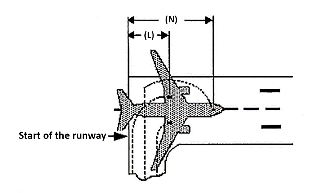
(a)The length of the runway that is declared for the calculation of take-off distance available (TODA), accelerate-stop distance available (ASDA) and take-off run available (TORA) does not account for line-up of the aeroplane in the direction of take-off on the runway in use. This alignment distance depends on the aeroplane geometry and access possibility to the runway in use. Accountability is usually required for a 90°-taxiway entry to the runway and 180°-turnaround on the runway. There are two distances to be considered:
(1)the minimum distance of the main wheels from the start of the runway for determining TODA and TORA,’L’; and
(2)the minimum distance of the most forward wheel(s) from the start of the runway for determining ASDA,’N’.
Figure 1
Line-up of the aeroplane in the direction of take-off — L and N
Where the aeroplane manufacturer does not provide the appropriate data, the calculation method given in (b) should be used to determine the alignment distance.
(b)Alignment distance calculation
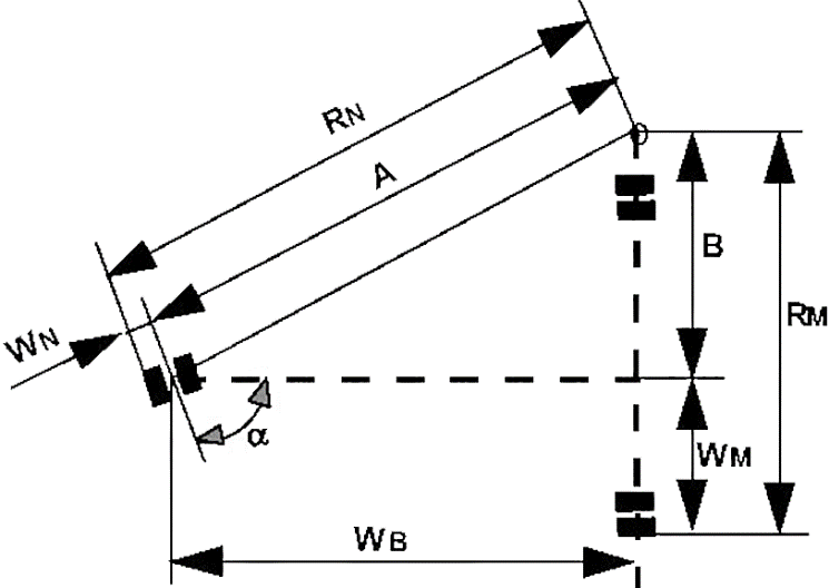
The distances mentioned in (a)(1) and (a)(2) are:
90° entry | 180° turnaround | |
L= | RM + X | RN + Y |
N= | RM + X + WB | RN + Y + WB |
where:
RN = A + WN = WB/cos(90°-α) + WN
RM = B + WM = WB tan(90°-α) + WM
X = safety distance of outer main wheel during turn to the edge of the runway
Y = safety distance of outer nose wheel during turn to the edge of the runway
Note: Minimum edge safety distances for X and Y are specified in FAA AC 150/5300-13 and ICAO Annex 14, 3.8.3
RN = radius of turn of outer nose wheel
RM = radius of turn of outer main wheel
WN = distance from aeroplane centre-line to outer nose wheel
WM = distance from aeroplane centre-line to outer main wheel
WB = wheel base
α = steering angle.
GM1 CAT.POL.A.205 Take-off
ED Decision 2014/015/R
RUNWAY SURFACE CONDITION
(a)Operation on runways contaminated with water, slush, snow or ice implies uncertainties with regard to runway friction and contaminant drag and, therefore, to the achievable performance and control of the aeroplane during take-off, since the actual conditions may not completely match the assumptions on which the performance information is based. In the case of a contaminated runway, the first option for the commander is to wait until the runway is cleared. If this is impracticable, he/she may consider a take-off, provided that he/she has applied the applicable performance adjustments, and any further safety measures he/she considers justified under the prevailing conditions.
(b)An adequate overall level of safety will only be maintained if operations in accordance with AMC 25.1591 or equivalent are limited to rare occasions. Where the frequency of such operations on contaminated runways is not limited to rare occasions, the operator should provide additional measures ensuring an equivalent level of safety. Such measures could include special crew training, additional distance factoring and more restrictive wind limitations.
CAT.POL.A.210 Take-off obstacle clearance
Regulation (EU) No 965/2012
(a)The net take-off flight path shall be determined in such a way that the aeroplane clears all obstacles by a vertical distance of at least 35 ft or by a horizontal distance of at least 90 m plus 0,125 × D, where D is the horizontal distance the aeroplane has travelled from the end of the take-off distance available (TODA) or the end of the take-off distance if a turn is scheduled before the end of the TODA. For aeroplanes with a wingspan of less than 60 m, a horizontal obstacle clearance of half the aeroplane wingspan plus 60 m, plus 0,125 × D may be used.
(b)When showing compliance with (a):
(1)The following items shall be taken into account:
(i)the mass of the aeroplane at the commencement of the take-off run;
(ii)the pressure altitude at the aerodrome;
(iii)the ambient temperature at the aerodrome; and
(iv)not more than 50 % of the reported headwind component or not less than 150 % of the reported tailwind component.
(2)Track changes shall not be allowed up to the point at which the net take-off flight path has achieved a height equal to one half the wingspan but not less than 50 ft above the elevation of the end of the TORA. Thereafter, up to a height of 400 ft it is assumed that the aeroplane is banked by no more than 15°. Above 400 ft height bank angles greater than 15°, but not more than 25° may be scheduled.
(3)Any part of the net take-off flight path in which the aeroplane is banked by more than 15° shall clear all obstacles within the horizontal distances specified in (a), (b)(6) and (b)(7) by a vertical distance of at least 50 ft.
(4)Operations that apply increased bank angles of not more than 20° between 200 ft and 400 ft, or not more than 30° above 400 ft, shall be carried out in accordance with CAT.POL.A.240.
(5)Adequate allowance shall be made for the effect of bank angle on operating speeds and flight path including the distance increments resulting from increased operating speeds.
(6)For cases where the intended flight path does not require track changes of more than 15°, the operator does not need to consider those obstacles that have a lateral distance greater than:
(i)300 m, if the pilot is able to maintain the required navigational accuracy through the obstacle accountability area; or
(ii)600 m, for flights under all other conditions.
(7)For cases where the intended flight path requires track changes of more than 15°, the operator does not need to consider those obstacles that have a lateral distance greater than:
(i)600 m, if the pilot is able to maintain the required navigational accuracy through the obstacle accountability area; or
(ii)900 m, for flights under all other conditions.
(c)The operator shall establish contingency procedures to satisfy the requirements in (a) and (b) and to provide a safe route, avoiding obstacles, to enable the aeroplane to either comply with the en-route requirements of CAT.POL.A.215, or land at either the aerodrome of departure or at a take-off alternate aerodrome.
AMC1 CAT.POL.A.210 Take-off obstacle clearance
ED Decision 2014/015/R
TAKE-OFF OBSTACLE CLEARANCE
(a)In accordance with the definitions used in preparing the take-off distance and take-off flight path data provided in the AFM:
(1)The net take-off flight path is considered to begin at a height of 35 ft above the runway or clearway at the end of the take-off distance determined for the aeroplane in accordance with (b) below.
(2)The take-off distance is the longest of the following distances:
(i)115 % of the distance with all engines operating from the start of the take-off to the point at which the aeroplane is 35 ft above the runway or clearway;
(ii)the distance from the start of the take-off to the point at which the aeroplane is 35 ft above the runway or clearway assuming failure of the critical engine occurs at the point corresponding to the decision speed (V1) for a dry runway; or
(iii)if the runway is wet or contaminated, the distance from the start of the take-off to the point at which the aeroplane is 15 ft above the runway or clearway assuming failure of the critical engine occurs at the point corresponding to the decision speed (V1) for a wet or contaminated runway.
(b)The net take-off flight path, determined from the data provided in the AFM in accordance with (a)(1) and (a)(2), should clear all relevant obstacles by a vertical distance of 35 ft. When taking off on a wet or contaminated runway and an engine failure occurs at the point corresponding to the decision speed (V1) for a wet or contaminated runway, this implies that the aeroplane can initially be as much as 20 ft below the net take-off flight path in accordance with (a) and, therefore, may clear close-in obstacles by only 15 ft. When taking off on wet or contaminated runways, the operator should exercise special care with respect to obstacle assessment, especially if a take-off is obstacle-limited and the obstacle density is high.
AMC2 CAT.POL.A.210 Take-off obstacle clearance
ED Decision 2014/015/R
EFFECT OF BANK ANGLES
(a)The AFM generally provides a climb gradient decrement for a 15° bank turn. For bank angles of less than 15°, a proportionate amount should be applied unless the manufacturer or AFM has provided other data.
(b)Unless otherwise specified in the AFM or other performance or operating manuals from the manufacturer, acceptable adjustments to assure adequate stall margins and gradient corrections are provided by the following table:
Table 1
Effect of bank angles
Bank | Speed | Gradient correction |
15° | V2 | 1 x AFM 15° gradient loss |
20° | V2 + 5 kt | 2 x AFM 15° gradient loss |
25° | V2 + 10 kt | 3 x AFM 15° gradient loss |
AMC3 CAT.POL.A.210 Take-off obstacle clearance
ED Decision 2014/015/R
REQUIRED NAVIGATIONAL ACCURACY
(a)Navigation systems
The obstacle accountability semi-widths of 300 m and 600 m may be used if the navigation system under OEI conditions provides a two standard deviation accuracy of 150 m and 300 m respectively.
(b)Visual course guidance
(1)The obstacle accountability semi-widths of 300 m and 600 m may be used where navigational accuracy is ensured at all relevant points on the flight path by use of external references. These references may be considered visible from the flight crew compartment if they are situated more than 45° either side of the intended track and with a depression of not greater than 20° from the horizontal.
(2)For visual course guidance navigation, the operator should ensure that the weather conditions prevailing at the time of operation, including ceiling and visibility, are such that the obstacle and/or ground reference points can be seen and identified. The operations manual should specify, for the aerodrome(s) concerned, the minimum weather conditions which enable the flight crew to continuously determine and maintain the correct flight path with respect to ground reference points, so as to provide a safe clearance with respect to obstructions and terrain as follows:
(i)the procedure should be well-defined with respect to ground reference points so that the track to be flown can be analysed for obstacle clearance requirements;
(ii)the procedure should be within the capabilities of the aeroplane with respect to forward speed, bank angle and wind effects;
(iii)a written and/or pictorial description of the procedure should be provided for crew use; and
(iv)the limiting environmental conditions (such as wind, the lowest cloud base, ceiling, visibility, day/night, ambient lighting, obstruction lighting) should be specified.
GM1 CAT.POL.A.210 Take-off obstacle clearance
ED Decision 2014/015/R
CONTINGENCY PROCEDURES FOR OBSTACLES CLEARANCES
If compliance with CAT.POL.A.210 is based on an engine failure route that differs from the all engine departure route or SID normal departure, a ‘deviation point’ can be identified where the engine failure route deviates from the normal departure route. Adequate obstacle clearance along the normal departure route with failure of the critical engine at the deviation point will normally be available. However, in certain situations the obstacle clearance along the normal departure route may be marginal and should be checked to ensure that, in case of an engine failure after the deviation point, a flight can safely proceed along the normal departure route.
CAT.POL.A.215 En-route – one-engine-inoperative (OEI)
Regulation (EU) 2023/217
(a)The OEI en-route net flight path data shown in the AFM, appropriate to the meteorological conditions expected for the flight, shall allow demonstration of compliance with (b) or (c) at all points along the route. The net flight path shall have a positive gradient at 1 500 ft above the aerodrome where the landing is assumed to be made after engine failure. In meteorological conditions requiring the operation of ice protection systems, the effect of their use on the net flight path shall be taken into account.
(b)The gradient of the en-route net flight path shall be positive at least 1 000 ft above all terrain and obstructions along the route within 9,3 km (5 NM) on either side of the intended track.
(c)The en-route net flight path shall permit the aeroplane to continue flight from the cruising altitude to an aerodrome where a landing can be made in accordance with point CAT.POL.A.230 or CAT.POL.A.235, as appropriate. The en-route net flight path shall clear vertically, by at least 2 000 ft, all terrain and obstructions along the route within 9,3 km (5 NM) on either side of the intended track, taking into account the following elements:
(1)the engine is assumed to fail at the most critical point along the route;
(2)account is taken of the effects of winds on the flight path;
(3)fuel jettisoning is permitted to an extent consistent with reaching the aerodrome where the aeroplane is assumed to land after engine failure with the required fuel reserves in accordance with point CAT.OP.MPA.181, appropriate for an alternate aerodrome, if a safe procedure is used;
(4)the aerodrome, where the aeroplane is assumed to land after engine failure, shall meet the following criteria:
(i)the performance requirements for the expected landing mass are met;
(ii)weather reports or forecasts and runway condition reports indicate that a safe landing can be accomplished at the estimated time of landing;
(5)if the AFM does not contain en-route net flight path data, the gross OEI en-route flight path shall be reduced by a climb gradient of 1,1 % for two-engined aeroplanes, 1,4 % for three-engined aeroplanes, and 1,6 % for four-engined aeroplanes.
(d)The operator shall increase the width margins provided for in points (b) and (c) to 18,5 km (10 NM) if the navigational accuracy does not meet at least navigation specification RNAV 5.
AMC1 CAT.POL.A.215 En-route – one-engine-inoperative (OEI)
ED Decision 2021/005/R
ROUTE ANALYSIS
(a)The high terrain or obstacle analysis required should be carried out by a detailed analysis of the route.
(b)A detailed analysis of the route should be made using contour maps of the high terrain and plotting the highest points within the prescribed corridor’s width along the route. The next step is to determine whether it is possible to maintain level flight with OEI 1 000 ft above the highest point of the crossing. If this is not possible, or if the associated weight penalties are unacceptable, a drift down procedure should be worked out, based on engine failure at the most critical point and clearing critical obstacles during the drift down by at least 2 000 ft. The minimum cruise altitude is determined by the intersection of the two drift down paths, taking into account allowances for decision making (see Figure 1). This method is time-consuming and requires the availability of detailed terrain maps.
(c)Alternatively, the published minimum flight altitudes (MEA or minimum off-route altitude (MORA)) should be used for determining whether OEI level flight is feasible at the minimum flight altitude, or if it is necessary to use the published minimum flight altitudes as the basis for the drift down construction (see Figure 1). This procedure avoids a detailed high terrain contour analysis, but could be more penalising than taking the actual terrain profile into account as in (b).
(d)In order to comply with CAT.POL.A.215 (c), one means of compliance is the use of MORA and, with CAT.POL.A.215 (d), MEA provided that the aeroplane meets the navigational equipment standard assumed in the definition of MEA.
Figure 1
Intersection of the two drift down paths
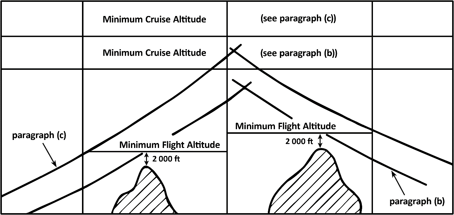
Note:MEA or MORA normally provide the required 2 000 ft obstacle clearance for drift down. However, at and below 6 000 ft altitude, MEA and MORA cannot be used directly as only 1 000 ft clearance is ensured.
CAT.POL.A.220 En-route – aeroplanes with three or more engines, two engines inoperative
Regulation (EU) 2021/1296
(a)An aeroplane that has three or more engines shall not be away from an aerodrome at which the requirements of points CAT.POL.A.230 or CAT.POL.A.235(a) for the expected landing mass are met accordingly, at any point along the intended track for more than 90 minutes, with all engines operating at cruising power or thrust, as appropriate, at standard temperature in still air, unless points (b) to (f) of this point are complied with.
(b)The two-engines-inoperative en-route net flight path data shall allow the aeroplane to continue the flight, in the expected meteorological conditions, from the point where two engines are assumed to fail simultaneously to an aerodrome at which it is possible to land and come to a complete stop when using the prescribed procedure for a landing with two engines inoperative. The en-route net flight path shall clear vertically, by at least 2 000 ft, all terrain and obstructions along the route within 9,3 km (5 NM) on either side of the intended track. At altitudes and in meteorological conditions that require ice protection systems to be operable, the effect of their use on the en-route net flight path data shall be taken into account. If the navigational accuracy does not meet at least navigation specification RNAV 5, the operator shall increase the prescribed width margin provided for in the second sentence to 18,5 km (10 NM).
(c)The two engines shall be assumed to fail at the most critical point of that portion of the route where the aeroplane is operated for more than 90 minutes, with all engines operating at cruising power or thrust, as appropriate, at standard temperature in still air, away from the aerodrome referred to in point (a).
(d)The net flight path shall have a positive gradient at 1 500 ft above the aerodrome where the landing is assumed to be made after the failure of two engines.
(e)Fuel jettisoning shall be permitted to an extent consistent with reaching the aerodrome with the required fuel reserves referred to in point (f), if a safe procedure is used.
(f)The expected mass of the aeroplane at the point where the two engines are assumed to fail shall not be less than that which would include sufficient fuel/energy to proceed to an aerodrome where the landing is assumed to be made, and to arrive there at an altitude of at least 1 500 ft (450 m) directly over the landing area, and thereafter, to fly for 15 minutes at cruising power or thrust, as appropriate.
CAT.POL.A.225 Landing – destination and alternate aerodromes
Regulation (EU) No 965/2012
(a)The landing mass of the aeroplane determined in accordance with CAT.POL.A.105(a) shall not exceed the maximum landing mass specified for the altitude and the ambient temperature expected for the estimated time of landing at the destination aerodrome and alternate aerodrome.
AMC1 CAT.POL.A.225 Landing – destination and alternate aerodromes
ED Decision 2014/015/R
ALTITUDE MEASURING
The operator should use either pressure altitude or geometric altitude for its operation and this should be reflected in the operations manual.
AMC2 CAT.POL.A.225 Landing – destination and alternate aerodromes
ED Decision 2014/015/R
MISSED APPROACH
(a)For instrument approaches with a missed approach climb gradient greater than 2.5 %, the operator should verify that the expected landing mass of the aeroplane allows for a missed approach with a climb gradient equal to or greater than the applicable missed approach gradient in the OEI missed approach configuration and at the associated speed.
(b)For instrument approaches with DH below 200 ft, the operator should verify that the expected landing mass of the aeroplane allows a missed approach gradient of climb, with the critical engine failed and with the speed and configuration used for a missed approach of at least 2.5 %, or the published gradient, whichever is greater.
GM1 CAT.POL.A.225 Landing – destination and alternate aerodromes
ED Decision 2014/015/R
MISSED APPROACH GRADIENT
(a)Where an aeroplane cannot achieve the missed approach gradient specified in AMC2 CAT.POL.A.225, when operating at or near maximum certificated landing mass and in engine-out conditions, the operator has the opportunity to propose an alternative means of compliance to the competent authority demonstrating that a missed approach can be executed safely taking into account appropriate mitigating measures.
(b)The proposal for an alternative means of compliance may involve the following:
(1)considerations to mass, altitude and temperature limitations and wind for the missed approach;
(2)a proposal to increase the DA/H or MDA/H; and
(3)a contingency procedure ensuring a safe route and avoiding obstacles.
CAT.POL.A.230 Landing – dry runways
Regulation (EU) 2023/217
(a)The landing mass of the aeroplane determined in accordance with point CAT.POL.A.105(a) for the estimated time of landing at the destination aerodrome and at any alternate aerodrome shall allow a full-stop landing from 50 ft above the threshold:
(1)for turbojet-powered aeroplanes, within 60 % of the landing distance available (LDA);
(2)for turbopropeller-powered aeroplanes, within 70 % of the LDA;
(3)by way of derogation from points (a)(1) and (a)(2), for aeroplanes that are approved for reduced landing distance operations under point CAT.POL.A.255, within 80 % of the LDA.
(b)For steep approach operations, the operator shall use the landing distance data factored in accordance with point (a)(1) or (a)(2), as applicable, based on a screen height of less than 60 ft, but not less than 35 ft, and shall comply with point CAT.POL.A.245.
(c)For short landing operations, the operator shall use the landing distance data factored in accordance with point (a)(1) or (a)(2), as applicable, and shall comply with point CAT.POL.A.250.
(d)When determining the landing mass, the operator shall take into account the following:
(1)not more than 50 % of the headwind component or not less than 150 % of the tailwind component;
(2)corrections as provided in the AFM.
(e)For dispatching the aeroplane, the aeroplane shall:
(1)land on the most favourable runway, in still air; and
(2)land on the runway most likely to be assigned, considering the probable wind speed and direction, the ground-handling characteristics of the aeroplane and other conditions such as landing aids and terrain.
(f)If the operator is unable to comply with point (e)(2) for the destination aerodrome, the aeroplane shall only be dispatched if an alternate aerodrome is designated that allows full compliance with one of the following:
(1)points (a) to (d), if the runway at the estimated time of arrival is dry;
(2)points CAT.POL.A.235(a) to (d), if the runway at the estimated time of arrival is wet or contaminated.
AMC1 CAT.POL.A.230 Landing — dry runways
ED Decision 2022/012/R
FACTORING OF AUTOMATIC LANDING DISTANCE PERFORMANCE DATA
In those cases where the landing requires the use of an automatic landing system, and the distance published in the AFM includes safety margins equivalent to those contained in CAT.POL.A.230(a)(1) and CAT.POL.A.230(a)(2), the landing mass of the aeroplane should be the lesser of:
(a)the landing mass determined in accordance with CAT.POL.A.230(a)(1) and CAT.POL.A.230(a)(2); or
(b)the landing mass determined for the automatic landing distance for the appropriate surface condition, as given in the AFM or equivalent document. Increments due to system features such as beam location or elevations, or procedures such as use of overspeed, should also be included.
AMC2 CAT.POL.A.230 Landing — dry runways
ED Decision 2022/012/R
FACTORING OF LANDING DISTANCE PERFORMANCE DATA WHEN USING A HEAD-UP DISPLAY (HUD) OR AN EQUIVALENT DISPLAY WITH FLARE CUE
In those cases where the landing requires the use of a HUD or an equivalent display with flare cue, and the landing distance published in the AFM includes safety factors, the landing mass of the aeroplane should be the lesser of:
(a)the landing mass determined in accordance with CAT.POL.A.230(a)(1); or
(b)the landing mass determined, when using a HUD or an equivalent display with flare cue for the appropriate surface condition, as given in the AFM or equivalent document.
GM1 CAT.POL.A.230 Landing – dry runways
ED Decision 2021/005/R
LANDING MASS
CAT.POL.A.230 establishes two considerations in determining the maximum permissible landing mass at the destination and alternate aerodromes:
(a)Firstly, the aeroplane mass will be such that on arrival the aeroplane can be landed within 60 %, 70 %, or 80 % (as applicable) of the landing distance available (LDA) on the most favourable (normally the longest) runway in still air. Regardless of the wind conditions, the maximum landing mass for an aerodrome/aeroplane configuration at a particular aerodrome cannot be exceeded.
(b)Secondly, consideration should be given to anticipated conditions and circumstances. The expected wind, or ATC and noise abatement procedures, may indicate the use of a different runway. These factors may result in a lower landing mass than that permitted under (a), in which case dispatch should be based on this lesser mass.
(c)The expected wind referred to in (b) is the wind expected to exist at the time of arrival.
GM1 CAT.POL.A.230 & CAT.POL.A.235 Landing — dry runways & Landing — wet and contaminated runways
ED Decision 2021/005/R
WORKFLOW OF THE LANDING DISTANCE ASSESSMENT AT THE TIME OF DISPATCH — GENERAL
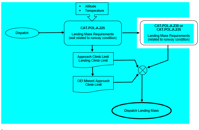
WORKFLOW OF THE LANDING DISTANCE ASSESSMENT AT THE TIME OF DISPATCH — RUNWAY SUITABILITY CHECK
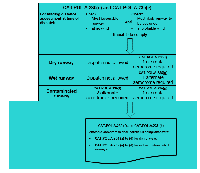
WORKFLOW OF THE LANDING DISTANCE ASSESSMENT AT THE TIME OF DISPATCH — DRY RUNWAYS
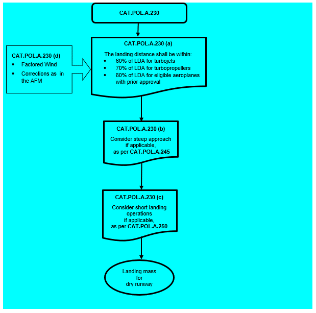
WORKFLOW OF THE LANDING DISTANCE ASSESSMENT AT THE TIME OF DISPATCH — WET RUNWAYS
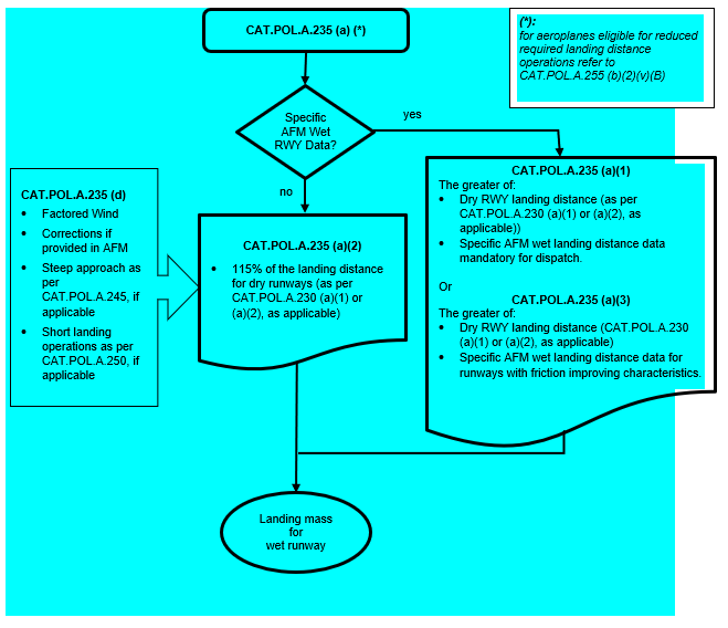
WORKFLOW OF THE LANDING DISTANCE ASSESSMENT AT THE TIME OF DISPATCH — CONTAMINATED RUNWAYS