
ED Decision 2005/006/R
The following criteria must be used for showing compliance with CS 25.302 for aeroplanes equipped with flight control systems, autopilots, stability augmentation systems, load alleviation systems, flutter control systems, and fuel management systems. If this appendix is used for other systems, it may be necessary to adapt the criteria to the specific system.
(a) The criteria defined herein only address the direct structural consequences of the system responses and performances and cannot be considered in isolation but should be included in the overall safety evaluation of the aeroplane. These criteria may in some instances duplicate standards already established for this evaluation. These criteria are only applicable to structure whose failure could prevent continued safe flight and landing. Specific criteria that define acceptable limits on handling characteristics or stability requirements when operating in the system degraded or inoperative mode are not provided in this appendix.
(b) Depending upon the specific characteristics of the aeroplane, additional studies may be required that go beyond the criteria provided in this appendix in order to demonstrate the capability of the aeroplane to meet other realistic conditions such as alternative gust or manoeuvre descriptions for an aeroplane equipped with a load alleviation system.
(c) The following definitions are applicable to this appendix.
Structural performance: Capability of the aeroplane to meet the structural requirements of CS-25.
Flight limitations: Limitations that can be applied to the aeroplane flight conditions following an in-flight occurrence and that are included in the flight manual (e.g., speed limitations, avoidance of severe weather conditions, etc.).
Operational limitations: Limitations, including flight limitations, that can be applied to the aeroplane operating conditions before dispatch (e.g., fuel, payload and Master Minimum Equipment List limitations).
Probabilistic terms: The probabilistic terms (probable, improbable, extremely improbable) used in this appendix are the same as those used in CS 25.1309.
Failure condition: The term failure condition is the same as that used in CS 25.1309, however this appendix applies only to system failure conditions that affect the structural performance of the aeroplane (e.g., system failure conditions that induce loads, change the response of the aeroplane to inputs such as gusts or pilot actions, or lower flutter margins).
[Amdt 25/1]
K25.2 Effects of Systems on Structures
ED Decision 2005/006/R
(a) General. The following criteria will be used in determining the influence of a system and its failure conditions on the aeroplane structure.
(b) System fully operative. With the system fully operative, the following apply:
(1) Limit loads must be derived in all normal operating configurations of the system from all the limit conditions specified in Subpart C, taking into account any special behaviour of such a system or associated functions or any effect on the structural performance of the aeroplane that may occur up to the limit loads. In particular, any significant nonlinearity (rate of displacement of control surface, thresholds or any other system nonlinearities) must be accounted for in a realistic or conservative way when deriving limit loads from limit conditions.
(2) The aeroplane must meet the strength requirements of CS-25 (Static strength, residual strength), using the specified factors to derive ultimate loads from the limit loads defined above. The effect of nonlinearities must be investigated beyond limit conditions to ensure the behaviour of the system presents no anomaly compared to the behaviour below limit conditions. However, conditions beyond limit conditions need not be considered when it can be shown that the aeroplane has design features that will not allow it to exceed those limit conditions.
(3) The aeroplane must meet the aeroelastic stability requirements of CS 25.629.
(c) System in the failure condition. For any system failure condition not shown to be extremely improbable, the following apply:
(1) At the time of occurrence. Starting from 1-g level flight conditions, a realistic scenario, including pilot corrective actions, must be established to determine the loads occurring at the time of failure and immediately after failure.
(i) For static strength substantiation, these loads multiplied by an appropriate factor of safety that is related to the probability of occurrence of the failure are ultimate loads to be considered for design. The factor of safety (F.S.) is defined in Figure 1.
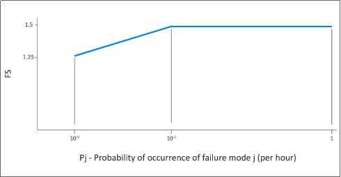
Figure 1 Factor of safety at the time of occurrence
(ii) For residual strength substantiation, the aeroplane must be able to withstand two thirds of the ultimate loads defined in subparagraph (c)(1)(i). For pressurised cabins, these loads must be combined with the normal operating differential pressure.
(iii) Freedom from aeroelastic instability must be shown up to the speeds defined in CS 25.629(b)(2). For failure conditions that result in speed increases beyond VC/MC, freedom from aeroelastic instability must be shown to increased speeds, so that the margins intended by CS 25.629(b)(2) are maintained.
(iv) Failures of the system that result in forced structural vibrations (oscillatory failures) must not produce loads that could result in detrimental deformation of primary structure.
(2) For the continuation of the flight. For the aeroplane, in the system failed state and considering any appropriate reconfiguration and flight limitations, the following apply:
(i) The loads derived from the following conditions at speeds up to VC / MC, or the speed limitation prescribed for the remainder of the flight must be determined:
(A) the limit symmetrical manoeuvring conditions specified in CS 25.331 and in CS 25.345.
(B) the limit gust and turbulence conditions specified in CS 25.341 and in CS 25.345.
(C) the limit rolling conditions specified in CS 25.349 and the limit unsymmetrical conditions specified in CS 25.367 and CS 25.427(b) and (c).
(D) the limit yaw manoeuvring conditions specified in CS 25.351.
(E) the limit ground loading conditions specified in CS 25.473 and CS 25.491.
(ii) For static strength substantiation, each part of the structure must be able to withstand the loads in subparagraph (2)(i) of this paragraph multiplied by a factor of safety depending on the probability of being in this failure state. The factor of safety is defined in Figure 2.
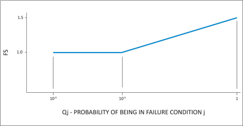
Figure 2 Factor of safety for continuation of flight
Qj = (Tj)(Pj) where:
Tj = Average time spent in failure condition j (in hours)
Pj = Probability of occurrence of failure mode j (per hour)
Note: If Pj is greater than 10-3, per flight hour then a 1.5 factor of safety must be applied to all limit load conditions specified in Subpart C.
(iii) For residual strength substantiation, the aeroplane must be able to withstand two thirds of the ultimate loads defined in subparagraph (c)(2)(ii). For pressurised cabins, these loads must be combined with the normal operating differential pressure.
(iv) If the loads induced by the failure condition have a significant effect on fatigue or damage tolerance then their effects must be taken into account.
(v) Freedom from aeroelastic instability must be shown up to a speed determined from Figure 3. Flutter clearance speeds V' and V'' may be based on the speed limitation specified for the remainder of the flight using the margins defined by CS 25.629(b).
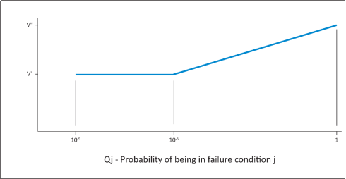
Figure 3: Clearance speed
V' = Clearance speed as defined by CS 25.629(b)(2).
V'' = Clearance speed as defined by CS 25.629(b)(1).
Qj = (Tj)(Pj) where:
Tj = Average time spent in failure condition j (in hours)
Pj = Probability of occurrence of failure mode j (per hour)
Note: If Pj is greater than 10-3 per flight hour, then the flutter clearance speed must not be less than V''.
(vi) Freedom from aeroelastic instability must also be shown up to V' in Figure 3 above, for any probable system failure condition combined with any damage required or selected for investigation by CS 25.571(b).
(3) Consideration of certain failure conditions may be required by other Subparts of CS-25 regardless of calculated system reliability. Where analysis shows the probability of these failure conditions to be less than 10-9, criteria other than those specified in this paragraph may be used for structural substantiation to show continued safe flight and landing.
(d) Failure indications. For system failure detection and indication, the following apply:
(1) The system must be checked for failure conditions, not extremely improbable, that degrade the structural capability below the level required by CS-25 or significantly reduce the reliability of the remaining system. As far as reasonably practicable, the flight crew must be made aware of these failures before flight. Certain elements of the control system, such as mechanical and hydraulic components, may use special periodic inspections, and electronic components may use daily checks, in lieu of detection and indication systems to achieve the objective of this requirement. These certification maintenance requirements must be limited to components that are not readily detectable by normal detection and indication systems and where service history shows that inspections will provide an adequate level of safety.
(2) The existence of any failure condition, not extremely improbable, during flight that could significantly affect the structural capability of the aeroplane and for which the associated reduction in airworthiness can be minimised by suitable flight limitations, must be signalled to the flight crew. For example, failure conditions that result in a factor of safety between the aeroplane strength and the loads of Subpart C below 1.25, or flutter margins below V", must be signalled to the crew during flight.
(e) Dispatch with known failure conditions. If the aeroplane is to be dispatched in a known system failure condition that affects structural performance, or affects the reliability of the remaining system to maintain structural performance, then the provisions of CS 25.302 must be met for the dispatched condition and for subsequent failures. Flight limitations and expected operational limitations may be taken into account in establishing Qj as the combined probability of being in the dispatched failure condition and the subsequent failure condition for the safety margins in Figures 2 and 3. These limitations must be such that the probability of being in this combined failure state and then subsequently encountering limit load conditions is extremely improbable. No reduction in these safety margins is allowed if the subsequent system failure rate is greater than 10-3 per hour.
[Amdt 25/1]
Appendix L
ED Decision 2005/006/R
|
Element of System |
Strength Value |
Remarks |
|
|
Proof |
Ultimate |
||
|
Rigid pipes and ducts Couplings Flexible hoses Return line elements |
1·5 PW 1·5 PW 2·0 PW – |
3·0 PW 3·0 PW 4·0 PW 1·5 Pf |
Pf The maximum pressure applied during failure conditions. |
|
Components other than pipes, couplings, ducts or pressure vessels |
1·5 PW |
2·0 PW |
|
|
Pressure vessels fabricated from metallic materials.
(For non-metallic materials see CS 25.1436(b)(7))
Pressure vessels connected to a line source of pressure
Pressure vessels not connected to a line source of pressure, e.g. emergency vessels inflated from a ground source |
3·0 PL or 1·5 PL |
4·0 PL or 2·0 PL |
The lower values are conditional upon justification by a fatigue endurance test from which a permissible fatigue life is declared, and upon the ultimate load test being made on the test specimen used for the fatigue life test.
The lower values are conditional upon justification by a life endurance test of a suitably factored permissible number of inflation/deflation cycles, including temperature fluctuation results in a significant pressure variation, and upon the ultimate load test being made on the test specimen used for the life endurance test.
For all pressure vessels: (1) The minimum acceptable conditions for storage, handling and inspection are to be defined in the appropriate manual. See CS 25.1529. (2) The proof factor is to be sustained for at least three minutes. (3) The ultimate factor is to be sustained for at least one minute. The factor having been achieved, the pressure vessel may be isolated from the pressure source for the remaining portion of the test period. |
|
2·5 PL or 1·5 PL |
3·0 PL or 2·0 PL |
||
[Amdt 25/1]