
CS 25.571 Damage tolerance and fatigue evaluation of structure
ED Decision 2017/015/R
(See AMC 25.571)
(a) General. An evaluation of the strength, detail design, and fabrication must show that catastrophic failure due to fatigue, manufacturing defects, environmental deterioration, or accidental damage, will be avoided throughout the operational life of the aeroplane. This evaluation must be conducted in accordance with the provisions of subparagraphs (b) of this paragraph, except as specified in subparagraph (a)(4) of this paragraph, for each part of the structure that could contribute to a catastrophic failure. Additionally, a discrete source damage evaluation must be conducted in accordance with subparagraph (e) of this paragraph, and those parts which could contribute to a catastrophic failure must also be evaluated in accordance with subparagraph (d) of this paragraph. In addition, the following apply:
(1) The evaluations of subparagraphs (b) and (c) must include:
(i) The typical loading spectra, temperatures, and humidities expected in service;
(ii) The identification of principal structural elements and detail design points, the failure of which could contribute to a catastrophic failure of the aeroplane; and
(iii) An analysis, supported by test evidence, of the principal structural elements and detail design points identified in sub-paragraph (a)(1)(ii) of this paragraph.
(2) The service history of aeroplanes of similar structural design, taking due account of differences in operating conditions and procedures, may be used in the evaluations required by this paragraph.
(3) Based on the evaluations required by this paragraph, inspections or other procedures must be established as necessary to prevent catastrophic failure, and must be included in the Airworthiness Limitations Section of the Instructions for Continued Airworthiness required by CS 25.1529. The limit of validity of the engineering data that supports the structural maintenance programme (hereafter referred to as LOV), stated as a number of total accumulated flight cycles or flight hours or both, established by this paragraph, must also be included in the Airworthiness Limitations Section of the Instructions for Continued Airworthiness.
(4) If the results of the evaluation required by subparagraph (b) show that damage tolerance-based inspections are impractical, then an evaluation must be performed in accordance with the provisions of subparagraph (c).
If the results of the evaluation show that damage tolerance-based inspections are practical, then inspection thresholds must be established for all principal structural elements and detail design points. For the following types of structure, the threshold must be established based on analyses and/or tests, assuming the structure contains an initial flaw representative of a defect or damage of the maximum probable size that could exist as a result of manufacturing processes or manufacturing or service-induced damage:
(i) single load path structure; and
(ii) multiple load path ‘fail-safe’ structure and crack arrest ‘fail-safe’ structure, where it cannot be demonstrated that the resulting load path failure or partial failure (including arrested cracks) will be detected and repaired during normal maintenance, inspection, or operation of an aeroplane prior to failure of the remaining structure.
(5) Inspection programmes must be established to protect the structure evaluated under subparagraph (b) and (c) against the effects of environmental deterioration and service-induced accidental damage. In addition, a baseline corrosion and prevention control programme (CPCP) must be established. The Airworthiness Limitations Section of the Instructions for Continued Airworthiness must include a statement that requires the operator to include a CPCP in their maintenance programme that will control corrosion to Level 1 or better.
(b) Fatigue and damage tolerance evaluation. The evaluation must include a determination of the probable locations and modes of damage due to fatigue, environmental deterioration (e.g. corrosion), or accidental damage. Repeated load and static analyses, supported by test evidence and (if available) service experience, must be incorporated in the evaluation. Damage at multiple sites due to prior fatigue exposure (including special consideration of widespread fatigue damage) must be included in the evaluation where the design is such that this type of damage could occur. An LOV must be established that corresponds to the period of time, stated as a number of total accumulated flight cycles or flight hours or both, for which it has been demonstrated by full-scale fatigue test evidence that widespread fatigue damage will not occur in the aeroplane structure.
The type certificate may be issued prior to completion of the full-scale fatigue testing provided that EASA has approved a plan for completing the required tests and analyses, and that at least one calendar year of safe operation has been substantiated at the time of type certification. In addition, the Airworthiness Limitations Section of the Instructions for Continued Airworthiness must specify an interim limitation restricting aircraft operation to not more than half the number of the flight cycles or flight hours accumulated on the fatigue test article, until such testing is completed, freedom from widespread fatigue damage has been established and the LOV is approved.
The extent of damage for residual strength evaluation at any time within the operational life of the aeroplane must be consistent with the initial detectability and subsequent growth under repeated loads. The residual strength evaluation must show that the remaining structure is able to withstand loads (considered as static ultimate loads) corresponding to the following conditions:
(1) The limit symmetrical manoeuvring conditions specified in CS 25.331 at all speeds up to VC and in CS 25.345.
(2) The limit gust conditions specified in CS 25.341 at the specified speeds up to VC and in CS 25.345.
(3) The limit rolling conditions specified in CS 25.349 and the limit unsymmetrical conditions specified in CS 25.367 and CS 25.427(a) through (c), at speeds up to VC.
(4) The limit yaw manoeuvring conditions specified in CS 25.351 at the specified speeds up to VC.
(5) For pressurised cabins, the following conditions:
(i) The normal operating differential pressure combined with the expected external aerodynamic pressures applied simultaneously with the flight loading conditions specified in sub-paragraphs (b)(1) to (b)(4) of this paragraph if they have a significant effect.
(ii) The maximum value of normal operating differential pressure (including the expected external aerodynamic pressures during 1 g level flight) multiplied by a factor of 1·15 omitting other loads.
(6) For landing gear and other affected airframe structure, the limit ground loading conditions specified in CS 25.473, CS 25.491 and CS 25.493.
If significant changes in structural stiffness or geometry, or both, follow from a structural failure, or partial failure, the effect on damage tolerance must be further evaluated.
(c) Fatigue (safe-life) evaluation. Compliance with the damage-tolerance requirements of sub-paragraph (b) of this paragraph is not required if the applicant establishes that their application for particular structure is impractical. This structure must be shown by analysis, supported by test evidence, to be able to withstand the repeated loads of variable magnitude expected during its service life without detectable cracks. Appropriate safe-life scatter factors must be applied. Until such time as all testing that is required for compliance with this subparagraph is completed, the replacement times provided in the Airworthiness Limitations Section of the Instructions for Continued Airworthiness may not exceed the total accumulated flight cycles on the test article test life divided by the applicable scatter factor.
(d) Sonic fatigue strength. It must be shown by analysis, supported by test evidence, or by the service history of aeroplanes of similar structural design and sonic excitation environment, that:
(1) Sonic fatigue cracks are not probable in any part of the flight structure subject to sonic excitation; or
(2) Catastrophic failure caused by sonic fatigue cracks is not probable assuming that the loads prescribed in sub-paragraph (b) of this paragraph are applied to all areas affected by those cracks.
(e) Discrete source damage tolerance evaluation. The aeroplane must be capable of successfully completing a flight during which likely structural damage occurs as a result of bird impact as specified in CS 25.631.
The damaged structure must be able to withstand the static loads (considered as ultimate loads) which are reasonably expected to occur at the time of the occurrence and during the completion of the flight. Dynamic effects on these static loads do not need to be considered. Corrective action to be taken by the pilot following the incident, such as limiting manoeuvres, avoiding turbulence, and reducing speed, may be considered. If significant changes in structural stiffness or geometry, or both, follow from a structural failure or partial failure, the effect on damage tolerance must be further investigated.
[Amdt 25/18]
[Amdt 25/19]
AMC 25.571 Damage tolerance and fatigue evaluation of structure
ED Decision 2017/017/R
1. PURPOSE
This AMC provides guidance for compliance with the provisions of CS 25.571 pertaining to the damage tolerance and fatigue evaluation requirements for aeroplane metallic and non-metallic structure. It also provides rational guidelines for the evaluation of scatter factors for the determination of life limits for parts categorised as safe-life. Additional guidance material for certification of non-metallic structures that must also comply with CS 25.571 is contained in AMC 20‑29.
2. (RESERVED)
3. REFERENCES
CS 25.571 Damage tolerance and fatigue evaluation of structure,
CS 25.1529 Instructions for Continued Airworthiness,
AMC 20-20 Continued Structural Integrity Programme,
AMC 20-29 Composite Structure.
4. DEFINITIONS OF TERMS USED IN THIS AMC
‘Damage tolerance’ is the attribute of the structure that permits it to retain its required residual strength without detrimental structural deformation for a period of use after the structure has sustained a given level of fatigue, environmental, accidental, or discrete source damage.
‘Fatigue critical structure (FCS)’ is structure that is susceptible to fatigue cracking that could lead to a catastrophic failure of an aircraft.
‘Safe-life’ of a structure is that number of events such as flights, landings, or flight hours, during which there is a low probability that the strength will degrade below its design ultimate value due to fatigue cracking.
‘Design service goal (DSG)’ is the period of time (in flight cycles or flight hours, or both) established at design and/or certification during which the aircraft structure is reasonably free from significant cracking.
‘Principal structure element (PSE)’ is an element that contributes significantly to the carrying of flight, ground, or pressurisation loads, and whose integrity is essential in maintaining the overall structural integrity of the aeroplane.
‘Detail design point (DDP)’ is an area of structure that contributes to the susceptibility of the structure to fatigue cracking or degradation such that the structure cannot maintain its load carrying capability, which could lead to a catastrophic failure.
In ‘single load path structure’ the applied loads are carried through a single structural member, the failure of which would result in the loss of the structural capability to carry the applied loads.
In ‘multiple load path structure’ the applied loads are distributed through redundant structural members so that the failure of a single structural member does not result in the loss of structural capability to carry the applied loads.
‘Widespread fatigue damage (WFD)’ in a structure is characterised by the simultaneous presence of cracks at multiple structural details that are of sufficient size and density whereby the structure will no longer meet the residual strength requirement of CS 25.571(b).
(1) ‘Multiple site damage (MSD)’ is a source of widespread fatigue damage characterised by the simultaneous presence of fatigue cracks in the same structural element.
(2) ‘Multiple element damage (MED)’ is a source of widespread fatigue damage characterised by the simultaneous presence of fatigue cracks in adjacent structural elements.
(3) ‘Structural modification point (SMP)’ is the point in time when a structural area must be modified to preclude WFD.
(4) ‘Inspection start point (ISP)’ is the point in time when special inspections of the fleet are initiated due to a specific probability of having an MSD/MED condition.
‘Scatter factor’ is a life reduction factor used in the interpretation of fatigue analysis and fatigue test results.
‘Limit of validity’ (LOV) of the engineering data that supports the structural maintenance programme is not more than the period of time, stated as a number of total accumulated flight cycles or flight hours or both, during which it is demonstrated by test evidence, analysis and, if available, service experience and teardown inspection results of high-time aeroplanes, that widespread fatigue damage will not occur in the aeroplane structure
‘Normal maintenance’ is understood to be those scheduled maintenance checks during minor or base maintenance inputs requiring general visual inspections and is normally associated with a zonal programme. The zonal programme is a collective term comprising selected general visual inspections and visual checks that are applied to each zone, defined by access and area, to check system and power plant installations and structure for security and general condition. A general visual inspection is a visual examination of an interior or exterior area, installation, or assembly to detect obvious damage, failure, or irregularity. This level of inspection is made from within touching distance unless otherwise specified. A mirror may be necessary to enhance visual access to all exposed surfaces in the inspection area. This level of inspection is made under normally available lighting conditions such as daylight, hangar lighting, flashlight, or droplight and may require removal or opening of access panels or doors. Stands, ladders, or platforms may be required to gain access.
‘Teardown inspection’ is the process of disassembling structure and using destructive inspection techniques or visual (magnified glass and dye penetrant) or other, and non-destructive inspection methods (eddy current, ultrasonic) to identify the extent of damage, within a structure, caused by fatigue, environmental and accidental damage.
‘Fail-safe’ is the attribute of the structure that permits it to retain its required residual strength for a period of unrepaired use after the failure or partial failure of a principal structural element.
‘WFD(average behaviour)’ is the point in time when, without intervention, 50 % of the fleet is expected to develop WFD for a particular structure.
‘Level 1 corrosion’ is:
damage occurring between successive inspections that is within allowable damage limits; or
damage occurring between successive inspections that does not require structural reinforcement, replacement or new damage tolerance based inspections; or
corrosion occurring between successive inspections that exceeds allowable limits but can be attributed to an event not typical of operator usage of other aircraft in the same fleet; or
light corrosion occurring repeatedly between inspections that eventually requires structural reinforcement, replacement, or new damage-tolerance-based inspections.
5. BACKGROUND
(a) Since the early 1970s, there have been significant state-of-the-art and industry-practice developments in the area of structural fatigue and fail-safe strength evaluation of transport category aeroplanes. Recognising that these developments could warrant some revision of the existing fatigue requirements of § 25.571 and 25.573 of 14 CFR Part 25, the Federal Aviation Administration (FAA), on 18 November 1976 (41 FR 50956), gave notice of the Transport Category Aeroplane Fatigue Regulatory Review Programme and invited interested persons to submit proposals to amend those requirements. The proposals and related discussions formed the basis for the revision of the structural fatigue evaluation standards of § 25.571 and § 25.573 of 14 CFR Part 25 and the development of guidance material. To that end, § 25.571 was revised, § 25.573 was deleted (the scope of § 25.571 was expanded to cover the substance of the deleted section), and guidance material (FAA AC 25.571-1) was provided which contained compliance provisions related to the proposed changes.
(b) Since the issuance of FAA AC 25.571-1 on 28 September 1978, additional guidance material, including information regarding discrete source damage, was developed and incorporated in revision 1A on 5 March 1986. The AC was further revised on 18.2.1997 (revision 1B) to add guidance on the elements to be considered in developing safe-life scatter factors for certification. Although FAR, JAR, and CS 25.571 have, since 1978, required consideration of fatigue damage originating at multiple sites, the FAA AC was further revised on 29 April 1998 (revision 1C) to add guidance material whose objective was to preclude widespread fatigue damage (resulting from MSD or MED) from occurring within the design service goal of the aeroplane, and to aid in the determination of thresholds for fatigue inspection and/or other special fleet actions. JAR/CS 25.571 were not harmonised with the 1998 amendment of 14 CFR 25.571. Under the auspices of the Aviation Rulemaking Advisory Committee (ARAC), the General Structure Harmonization Working Group (GSHWG) drafted NPA 25C-292 proposing the Limit of Validity (LOV), greater emphasis on testing, corrosion and manufacturing, and accidental damage in the 25.571 requirements and corresponding AC material to support this. EASA AMC 20-20 ‘Continuing Structural Integrity Programme’ introduced the LOV-concept in 2007. AC 25.571-1D, issued on 13 January 2011, provides guidance in support of 14 CFR 25 Amdt 132 which introduced the LOV requirement. Thus, AMC 25.571 has been revised to provide guidance for establishing an LOV for the structural maintenance programme as will now be required by CS 25.571. In conclusion, this AMC revision based on the GSHWG work and recently developed FAA guidance, now better harmonises with the EASA guidance, AC 25.571-1D, and industry practice.
6. INTRODUCTION
(a) General
The content of this AMC is considered by EASA in determining compliance with the requirements of CS 25.571. The objective is to prevent catastrophic structural failures caused by fatigue damage (FD) (including e.g. widespread fatigue damage (WFD)), environmental deterioration (ED) (e.g. corrosion damage), or accidental damage (AD).
Compliance involves good design practice to ensure that damage tolerance can be achieved and the establishment of maintenance actions developed in compliance with CS 25.1529. Taken together, they result in a structure where the combination of design characteristics and maintenance actions will serve to preclude any failure due to FD, ED, or AD.
CS 25.571(a)(3) requires the applicant to establish inspections or other procedures (herein also referred to as maintenance actions) as necessary to avoid catastrophic failure during the operational life of the aeroplane based on the results of the prescribed fatigue and damage tolerance evaluations.
CS 25.571(a)(5) requires development of inspections for ED and AD. CS 25.571(b) requires the applicant to establish an LOV. Furthermore, CS 25.571(b) and (c) require establishment of inspections and replacement times respectively based on the damage tolerance and fatigue characteristics of the structure. The LOV is, in effect, the operational life of the aeroplane consistent with the evaluations accomplished and maintenance actions established to prevent WFD. The LOV is established based on WFD considerations and it is intended that all maintenance actions required to address fatigue damage, environmental deterioration (e.g. corrosion damage for metallics, moisture for composites), and accidental damage (e.g. impact, lightning), up to the LOV, are identified in the structural maintenance programme. All inspections and other procedures (e.g. modification times, replacement times) that are necessary to prevent a catastrophic failure due to fatigue, up to the LOV, must be included in the Airworthiness Limitations Section (ALS) of the Instructions for Continued Airworthiness (ICA), as required by CS 25.1529, along with the LOV.
CS 25.571(d) requires the structure to be designed such that sonic fatigue cracking is not probable or, if it arises, it will not result in a catastrophic failure. CS 25.571(e) requires the structure to be designed to withstand damage caused by specified threats such that the flight during which the damage is sustained can be completed.
(1) CS 25.571(a)(5) — Environmental and accidental damage inspections and associated procedures
Inspections for ED and AD must be defined. Special consideration should be given to those areas where past service experience indicates a particular susceptibility to attack by the environment or vulnerability to impact and/or abuse. It is intended that these inspections will be effective in discovering ED or AD before it interacts with fatigue related phenomena, and that the ED or AD will, therefore, be removed/repaired before it presents a significant risk. Typically these inspections are largely defined based on past service experience using a qualitative or quantitative process in combination with the Airline Transportation Association (ATA) Maintenance Steering Group (MSG)-3 process. For new structure and materials, testing may be required to evaluate likely AD and the subsequent tolerance of the design to it. For ED prevention, an effective CPCP is necessary, which will contain tasks and procedures in addition to inspections that will help prevent initiation and, when necessary, the recurrence of corrosion (see AMC 20-20). Furthermore, CS 25.571 requires that the ALS must include a statement that requires the operator to include a CPCP in their maintenance programme that will control the corrosion to Level 1 or better.
Any special inspections required for AD and ED, i.e. ones in addition to those that would be generated through the use of the MSG-3 process for AD and ED, or the baseline CPCP development, and which are necessary to prevent catastrophic failure of the aeroplane, must be included in the ALS of the ICA required by CS 25.1529. If a location is prone to accidental or environmental damage and the only means for detection is one that relies on the subsequent development of a fatigue crack from the original damage, then that inspection must be placed in the ALS of the ICA.
Note: The AD and ED inspection programme including the baseline CPCP are equally applicable to structures showing compliance with CS 25.571(b) and (c) respectively.
(2) CS 25.571(b) and (c) — Fatigue damage inspections or replacement times
Inspections for fatigue damage or replacement times must be established as necessary. These actions must be based on quantitative evaluations of the fatigue characteristics of the structure. In general, analysis and testing will be required to generate the information needed. The applicant should perform crack growth and residual strength testing to produce the design data needed to support crack growth and residual strength analyses. Full-scale fatigue test evidence is required to support the evaluation of structure that is susceptible to WFD. Test evidence is needed to support analysis used to establish safe-life replacement times.
(i) Inspection or replacement
Compliance with CS 25.571(b) is required unless it can be demonstrated to the satisfaction of the authority that compliance cannot be shown due to practical constraints. Under these circumstances, compliance with CS 25.571(c) is required. The only common example of structure where compliance with the requirements of CS 25.571(c), in lieu of CS 25.571(b), might be accepted, would be the landing gear and its local attachments.
(ii) ALS of the ICA
All inspections and replacement times necessary to detect or preclude fatigue cracking scenarios, before they become critical, must be included in the ALS of the ICA required by CS 25.1529.
(iii) Limit of Validity (LOV)
An LOV for the structural maintenance programme must also be determined and included in the ALS of the ICA. See section 11 of this AMC for additional guidance on the LOV.
(b) Typical loading spectrum expected in service
The loading spectrum should be based on measured statistical data of the type derived from government and industry load history studies, and where insufficient data are available on a conservative estimate of the anticipated use of the aeroplane. The development of the loading spectrum includes the definition of the expected flight plan, which involves ground manoeuvres, climb, cruise, descent, flight times, operating speeds, weights and altitudes, and the approximate time to be spent in each of the operating regimes. The principal loads that should be considered in establishing a loading spectrum are flight loads (gust and manoeuvre), ground loads (taxiing, landing impact, turning, engine run-up, braking, thrust reversing and towing), and pressurisation loads. Operations for crew training and other pertinent factors, such as the dynamic stress characteristics of any flexible structure excited by turbulence or buffeting, should also be considered. For pressurised cabins, the loading spectrum should include the repeated application of the normal operating differential pressure and the superimposed effects of flight loads and aerodynamic pressures.
(c) Areas to be evaluated
When assessing the possibility of serious fatigue failures, the design should be examined to determine probable points of failure in service. In this examination consideration should be given, as necessary, to the results of stress analyses, static tests, fatigue tests, strain gauge surveys, tests of similar structural configurations, and service experience. Service experience has shown that special attention should be focused on the design details of important discontinuities, main attach fittings, tension joints, splices, and cut-outs such as windows, doors, and other openings. Locations prone to accidental damage (such as that due to the impact with ground servicing equipment near aeroplane doors) or to corrosion should be identified for analysis.
(d) Analyses and tests
Fatigue and damage tolerance analyses should be conducted unless it is determined that the normal operating stresses are of such a low order that crack initiation and, where applicable, significant damage growth is extremely improbable. Any method used in the analyses should be supported by test or service experience. Typical (average) values of fatigue respectively fracture mechanics material properties may be used in fatigue analysis respectively residual strength and crack growth analyses. The effects of environment on these properties should be accounted for if significant.
Generally, testing will also be necessary to support compliance with CS 25.571(b) or (c). The nature and extent of testing of complete structures or portions will depend on applicable previous design and structural tests and service experience with similar structures. Structural areas such as attachment fittings, major joints, changes in section, cut-outs, and discontinuities almost always require some level of testing in addition to analysis. When less than the complete structure is tested, care should be taken to ensure that the internal loads and boundary conditions are valid. When tests are conducted to support the identification of areas susceptible to fatigue, the duration of the test should take into account factors such as material and loading spectrum variability, together with the expected operational life. Refer to Appendix 2 for specific guidance regarding testing required to establish the LOV.
(e) Discrete source damage
It must be shown that the aeroplane is capable of successfully completing a flight during which specified incidents occur and result in immediately obvious damage. The maximum extent of the damage must be quantified and the structure must be shown to be capable of sustaining the maximum load (considered as ultimate) expected during the completion of the flight. There are no maintenance actions that result from this evaluation.
7. DAMAGE TOLERANCE EVALUATION
(a) General
The damage tolerance requirements of CS 25.571(b) are intended to ensure that, should fatigue, corrosion, or accidental damage occur within the LOV, the structure will be capable of withstanding the loading conditions specified in CS 25.571(b)(1) through (b)(6) without failure or detrimental structural deformation until the damage is detected. The evaluation should include identifying the PSEs, defining the loading conditions and conducting sufficiently representative structural tests or analyses, or both, to provide sufficient data for the establishment of the inspection programme. Although this process applies to either single or multiple load path structure, the use of multiple load path structures should be given priority in achieving a damage-tolerant design. The principle analytical tool used for metallic materials to perform a damage tolerance evaluation is based on fracture mechanics. A discussion of this approach is presented in Appendix 1 of this guidance material. The means of establishing the LOV and maintenance actions specifically associated to WFD is addressed in detail in Section 11 of this AMC.
(b) Damage-tolerant characteristics
A damage-tolerant structure has two notable attributes:
(1) The structure can tolerate a significant amount of damage, due to fatigue, environmental or accidental deterioration without compromising the continued airworthiness of the aeroplane (residual strength and rigidity).
(2) The structure can sustain that damage long enough to be found and repaired during scheduled or unscheduled maintenance (inspectability).
(c) Design considerations
To achieve a damage-tolerant structure, criteria should be established to guide the design process so that this design objective is achieved. The design process should include a damage tolerance evaluation (test and analysis) to demonstrate that the damage-tolerant design objectives are achieved, and to identify inspections or other procedures necessary to prevent catastrophic failure. Reliance on special inspections should be minimised by designing structure with easily detectable (e.g. visual) cracking modes. Since the occurrence of WFD can complicate a damage-tolerant evaluation to the point that reliable inspections programmes cannot be developed even with extremely intensive inspection methods, it must be demonstrated, with sufficient full-scale fatigue test evidence, that adequate maintenance procedures are contained in the ALS of the ICA, such that WFD will not occur within the LOV. A discussion on several issues that an applicant might face in demonstrating freedom from WFD is contained in Appendix 2 to this AMC.
(d) Design features
Design features which should be considered in attaining a damage-tolerant structure include the following:
(1) multiple load path construction and/or the use of damage containment features to arrest fast fracture or reduce the crack growth rate, and to provide adequate residual strength;
(2) materials and stress levels that provide a slow rate of crack propagation combined with high residual strength; and
(3) arrangement of design details to ensure a sufficiently high probability that a failure in any critical structural element will be detected before the strength has been reduced below the level necessary to withstand the loading conditions specified in CS 25.571(b).
(e) Probabilistic evaluations
No guidance is provided in this AMC on probabilistic evaluation. Normally, damage tolerance assessments consist of a deterministic evaluation of design features described in paragraphs 7(d)(1), (2) and (3). Paragraphs (f) to (i) below provide guidelines for this approach.
(f) PSEs, detail design points, and locations to be evaluated
In accordance with CS 25.571(a), a damage tolerance and fatigue evaluation should be conducted for each part of the structure which could contribute to a catastrophic failure. PSEs such as wing, empennage, control surfaces and their systems, the fuselage, engine mountings, landing gears, and their related primary attachments, and all DDPs susceptible to fatigue that could contribute to a catastrophic failure should be evaluated.
In accordance with CS 25.571(a)(1)(ii), this evaluation must include the identification of PSEs and DDPs, the failure of which could contribute to catastrophic failure of the aeroplane. As defined in this AMC, a principal structural element is an element of structure that contributes significantly to the carrying of flight, ground, or pressurisation loads and whose integrity is essential in maintaining the overall structural integrity of the aeroplane. When identifying PSEs, consideration should be given to the effect caused by partial or complete loss or failure of structure with respect to continued safe flight and landing, considering all flight phases including stability, control and aeroelasticity.
A DDP is an area at higher risk of fatigue cracking than other areas, and may warrant specific actions such as special inspections or other procedures to ensure continued airworthiness.
(1) Locations requiring evaluation can be determined by analysis or by fatigue tests on complete structures or subcomponents. However, tests may be necessary when the basis for analytical prediction is not reliable, such as for complex components. If less than the complete structure is tested, care should be taken to ensure that the internal loads and boundary conditions are valid.
The selection criteria for DDPs should also include the following considerations:
(a) any evidence of cracking encountered in service on a comparable structure;
(b) any evidence of cracking found during fatigue testing on a comparable structure;
(c) available strain gauge data;
(d) locations where permanent deformation occurred on static test articles;
(e) areas analytically shown to have a relatively low crack initiation life;
(f) susceptibility to corrosion or other environmental deterioration (e.g. disbonding);
(g) potential for manufacturing anomalies (e.g. new or novel manufacturing processes where the potential for damage may not be well understood);
(h) vulnerability to in-service induced accidental damage;
(i) areas whose failure would create high stresses in the remaining structure;
(j) elements in high tension or shear;
(k) low static margin;
(l) high stress concentrations;
(m) high load transfer;
(n) materials with high crack growth rates;
(o) some DDPs may exist outside of PSEs and may also have been classified as fatigue critical structure, e.g. undercarriage door attachments (see Appendix 5 for discussion on PSEs, FCS and DDP);
(p) areas where detection of damage would be difficult;
(q) locations subject to vibrations or other mechanisms that may lead to premature wear fastener holes; and
(r) locations vulnerable to moisture ingress or retention.
(2) Examples of principal structural elements (PSEs)
Typical examples of structure which are usually considered to be PSEs are:
(i) Wing and empennage
(a) control surfaces, slats, flaps, and their mechanical systems and attachments (hinges, tracks, and fittings);
(b) primary fittings;
(c) principal splices;
(d) skin or reinforcement around cut-outs or discontinuities;
(e) skin-stringer combinations or integrally stiffened plates;
(f) spar caps;
(g) spar webs; and
(h) ribs and bulkheads.
(ii) Fuselage
(a) circumferential frames and adjacent skin;
(b) pilot window posts;
(c) pressure bulkheads;
(d) skin and any single frame or stiffener element around a cut-out;
(e) skin or skin splices, or both, under circumferential loads;
(f) skin or skin splices, or both, under fore and aft loads;
(g) skin and stiffener combinations under fore and aft loads;
(h) door skins, frames, stops and latches;
(i) window frames; and
(j) floor beams3 Floor beams are not always critical but should be checked for criticality, particularly those located next to cut-outs or within non-circular pressurised sections..
(iii) Landing gear and their attachments
(iv) Engine mounts and struts
(v) Thrust reverser components, whose failure could result in inadvertent deployment
(3) Extent of Damage.
Each particular design should be assessed to establish appropriate damage criteria in relation to inspectability and damage-extension characteristics. In any damage determination, including those involving multiple cracks, it is possible to establish the extent of damage in terms of detectability with the inspection techniques to be used, the associated initially detectable crack size, the residual strength capabilities of the structure, and the likely damage-extension rate considering the expected stress redistribution under the repeated loads expected in service and with the expected inspection frequency. Thus, an obvious partial failure could be considered to be the extent of the damage or residual strength assessment, provided a positive determination is made that the fatigue cracks will be detectable by the available inspection techniques at a sufficiently early stage of the crack development. The following are typical examples of partial failures which should be considered in the evaluation:
(i) Detectable skin cracks emanating from the edge of structural openings or cutouts;
(ii) A detectable circumferential or longitudinal skin crack in the basic fuselage structure;
(iii) Complete severance of interior frame elements or stiffeners in addition to a detectable crack in the adjacent skin;
(iv) A detectable failure of one element where dual construction is utilised in components such as spar caps, window posts, window or door frames, and skin structure;
(v) The presence of a detectable fatigue failure in at least the tension portion of the spar web or similar element; and
(vi) The detectable failure of a primary attachment, including a control surface hinge and fitting.
(g) Inaccessible areas
Every reasonable effort should be made to ensure inspectability (reference CS 25.611) of all structural parts. In those cases where inaccessible and uninspectable blind areas exist, the damage tolerance evaluation should allow for extension of damage into detectable areas or demonstrate sufficient residual strength up to the LOV without inspection.
(h) Residual strength testing of principal structural elements
Analytical prediction of the residual strength of structures can be very complex due to non-linear behaviour, load redistribution and the potential for a multiplicity of failure modes. The nature and extent of residual strength tests will depend on previous experience with similar structures. Simulated cracks should be as representative as possible of actual fatigue damage. Where it is not practical to produce actual fatigue cracks, damage can be simulated by cuts made with a fine saw, sharp blade, guillotine, or other suitable means. Whatever artificial means are used to simulate sharp fatigue cracks, sufficient evidence should be available from tests to indicate equivalent residual strength. If equivalency cannot be shown, every attempt should be made to apply enough cyclic loading to generate fatigue cracks from the artificial damage prior to applying residual strength loads. Special consideration should be given to the procedure for pre-cracking so that subsequent test results are representative. This can be an issue when slow stable tearing in ductile sheet or plate material is part of the failure mechanism. Inappropriate pre-cracking loads can lead to non-conservative results. In those cases where bolt failure, or its equivalent, is to be simulated as part of a possible damage configuration in joints or fittings, bolts can be removed to provide that part of the simulation.
(i) Damage tolerance analysis and tests
(1) It should be determined by analysis, supported by test evidence, that:
(i) the structure, with the extent of damage established for residual strength evaluation, can withstand the specified residual strength loads (considered as ultimate loads); and
(ii) the crack growth life under the repeated loads expected in service (between the time the damage becomes initially detectable and the time the extent of damage reaches the value for residual strength evaluation) provides a practical basis for development of the inspection programme and procedures described in Section 8 of this AMC.
(2) The repeated loads should be as defined in the loading, temperature, and humidity spectra. The loading conditions should take into account the effects of structural flexibility and rate of loading where they are significant.
(3) The damage tolerance characteristics can be shown analytically by reliable or conservative methods such as the following:
(i) By demonstrating quantitative relationships with structure already verified as damage-tolerant; or
(ii) By demonstrating that the repeated loads and residual strength load stresses do not exceed those of previously verified designs of similar configuration, materials, and inspectability.
8. INSPECTION REQUIREMENTS
(a) Damage detection
Detection and repair of damage before it becomes critical is the most important factor in ensuring that the damage tolerance characteristics of the structure are maintained. For this reason, CS 25.571 requires that the applicant establish inspections or other procedures, as necessary, to prevent catastrophic failure from accidental, environmental, or fatigue damage, and include those inspections and procedures in the ALS of the Instructions for Continued Airworthiness required by CS 25.1529 (see also Appendix H to Part-25).
Due to the complex interactions of the many parameters that affect the damage tolerance evaluation, such as operating practices, environmental effects, load sequence effects on crack growth, and variations in inspection methods, operational experience should be taken into account in establishing inspection thresholds, repeat intervals, and inspection procedures.
(b) Environmental and accidental damage inspection programmes
The inspections developed under CS 25.571(b) are primarily for the detection of cracks developing from fatigue, accidental damage, and corrosion. As required by CS 25.571(a)(5), a separate programme needs to be implemented for the early detection of environmental and accidental damage. This is intended to minimise the risk of:
(1) interaction between corrosion and fatigue cracking;
(2) accidental damage developing into fatigue cracks; or
(3) corrosion developing due to accidental damage.
In many cases this can be accomplished through the Maintenance Review Board (MRB) activity or equivalent process agreed by EASA, for a new large aeroplane model using MSG-3 procedures. These procedures also require that a CPCP be developed.
For ED and AD programmes developed under the auspices of the MRB, the minimum ALS content associated with AD and ED may generally be limited to:
— a reference to the documents that contain the MRB report (MRBR) derived maintenance tasks for AD and ED; and
— the need to incorporate and maintain an effective CPCP in the operators’ programme; and
— a statement requiring operators to control corrosion to Level 1 or better.
It is also important to explain to operators the link between the AD and ED inspection programmes and CS 25.571 and CS 25.1529 compliance.
Inspections that are designed to detect fatigue cracking resulting from AD or ED, where the originating damage cannot otherwise be demonstrated to be detected prior to the development of the fatigue cracks, must also be directly included in the ALS. For new structure where there is limited supporting data from service experience, the MRB will depend heavily on input from the analyses and test programmes conducted by the applicant during certification, and for this reason significant cooperation is required between those involved directly in certification and those participating in the MRBR development. Care should also be taken to ensure that the damage assumptions made remain conservative after entry into service. A check of the continued validity of the certification assumptions can be achieved through fleet leader programmes and robust reporting requirements. If there is any doubt about the likely performance of a completely new structure with respect to AD and ED, certain specific inspections in vulnerable areas may be better placed in the ALS.
The baseline CPCP may be established through the MRB Industry Steering Committee (ISC) using existing procedures for MRBR development or developed by the applicant and submitted directly to EASA. (Note: Provided the operator has an NAA-approved maintenance programme that controls corrosion to Level 1 or better, it does not need to follow exactly the baseline CPCP offered by the type certificate holder (TCH). However, all revisions to the TCH’s programme for ED and AD must be considered by the operator for incorporation in the operators MP under the Part-M requirements.)
Reporting requirements for these programmes should extend to overhaul procedures where the condition of the part should be assessed and reported if outside of approved limits, whether or not it is to remain on the component being overhauled.
Changes and supplemental type certificates (STC) must also be provided with inspection programmes that address ED and AD.
(c) Inspection threshold for fatigue cracking
The inspection threshold is the point in time at which the first planned structural inspection is performed following entry into service. The threshold may be as low as the repeat interval, or may allow for a longer period of operation, provided certain conditions are met.
The concept of delaying an inspection threshold beyond the repeat interval is based on the premise that it will take a certain amount of time before fatigue cracks would develop to a size that would be detectable during a structural inspection. Consequently, it may be acceptable to wait some period of time before starting to inspect for fatigue cracks.
CS 25.571(a)(4) requires inspection thresholds for certain structure to be derived assuming that the structure contains an initial flaw of the maximum probable size that could exist as a result of manufacturing processes or manufacturing or service-induced damage. For metallic structure this would typically be achieved using crack growth analysis supported by tests. This approach applies to:
(1) single load path structure, and
(2) multiple load path ‘fail-safe’ structure and crack arrest ‘fail-safe’ structure, where it cannot be demonstrated that the resulting load path failure or partial failure (including arrested cracks) will be detected and repaired during normal maintenance, inspection, or operation of an aeroplane prior to failure of the remaining structure.
In this context, normal maintenance includes general visual structural inspections for accidental and environmental damage derived from processes such as the MRB application of MSG-3. Inspections should begin early enough to ensure that there is a high confidence of detecting cracks before they could lead to a catastrophic structural failure.
For the locations addressed by CS 25.571(a)(4) that are also susceptible to accidental (manufacturing or service induced) damage, the assumed initial flaw size for crack growth determination of the threshold should not be less than that which can be supported by service experience or test evidence. For example, if the type of damage expected is well defined, e.g. it is limited to dents, then there may be data that supports a longer threshold than would be derived by the assumption of a crack that is similar in size to the dent. However, in this case, the worst case manufacturing flaw should still be considered as a crack and the most conservative resulting threshold adopted. If supporting data is not available (e.g. for a completely new design where no specific investigation of the accidental damage threats or their influence on fatigue has been made), then the fatigue cracking inspection threshold should be set equal to the repeat interval derived for a crack detectable by general visual inspection means, since the initial damage and its growth is not well defined and could occur at any time.
The remaining areas of the structure evaluated under CS 25.571(b), i.e. multiple load path ‘fail-safe’ structure and crack arrest ‘fail-safe’ structure, where it can be demonstrated that the resulting load path failure, partial failure, or crack arrest will be detected and repaired during normal maintenance, inspection, or operation of an aeroplane prior to failure of the remaining structure must also have thresholds established for fatigue cracking. For these locations, methods that do not account for worst-case damage may be used in lieu of crack growth analysis if desired. For example, fatigue SN analysis and tests with an appropriate scatter factor or slow crack growth analysis based on appropriate initial manufacturing damage, i.e. typical manufacturing flaws as opposed to the maximum probable flaw (e.g. a 0.127 mm corner crack representing a typical manufacturing flaw in a fastener hole versus a 1.27 mm crack representing the maximum probable flaw).
The means of establishing the LOV and maintenance actions (including inspections) specifically associated to WFD is addressed in detail in Section 11 of this AMC.
All inspections necessary to detect fatigue cracking that have thresholds less than the approved operating limitation (LOV or interim limitations) of the maintenance programme must be included in the ALS.
Appendix 3 provides further details on threshold determination.
(d) Inspection
The basis for setting inspection intervals is the period of time during which damage is detectable and the residual strength remains above the required levels. The reliability of the repeat inspection programme (i.e. frequency of inspections and probability of detection) should assure damage detection before the residual strength of the aircraft is compromised. Inspection intervals must be established by applying appropriate reduction factors to this period to ensure that the crack or other damage or failed load path will typically be found well before the residual strength of the structure drops below the required level. Long periods of exposure to residual strength levels only just above the load limit should be avoided. This applies in particular to crack-arrest structure. It should be borne in mind that CS 25.305 is the principle requirement for strength of the airframe, and that CS 25.571 is primarily intended to provide an inspection programme that will ensure the timely detection and repair of damage in order to restore the aircraft to the required (CS 25.305) strength capability and preserve this capability throughout the majority of the aircraft’s operational life.
Detectable crack sizes and shapes assumed to determine inspection intervals should be consistent with the inspection method capabilities and the cracking characteristics of the structure being evaluated. If concurrent cracking in adjacent areas or surrounding structure is expected within the operational life of the aeroplane, then this should be accounted for in the cracking scenario assumed.
9. FATIGUE (SAFE-LIFE) EVALUATION
9.1. Reserved
9.2. Fatigue (safe-life) evaluation
9.2.1. General
The evaluation of structure under the following fatigue (safe-life) strength evaluation methods is intended to ensure that catastrophic fatigue failure, as a result of the repeated loads of variable magnitude expected in service, will be avoided throughout the structure’s operational life. Under these methods the fatigue life of the structure should be determined. The evaluation should include the following:
(a) estimating or measuring the expected loading spectra of the structure;
(b) conducting a structural analysis, including consideration of the stress concentration effects;
(c) performing fatigue testing of structure which cannot be related to a test background to establish response to the typical loading spectrum expected in service;
(d) determining reliable replacement times by interpreting the loading history, variable load analyses, fatigue test data, service experience, and fatigue analysis;
(e) evaluating the possibility of fatigue initiation from sources such as corrosion, stress corrosion, disbonding, accidental damage, and manufacturing defects based on a review of the design, quality control, and past service experience; and
(f) providing necessary maintenance instructions including replacement times in the ICA in accordance with CS 25.1529.
9.2.2. Scatter factor for safe-life determination
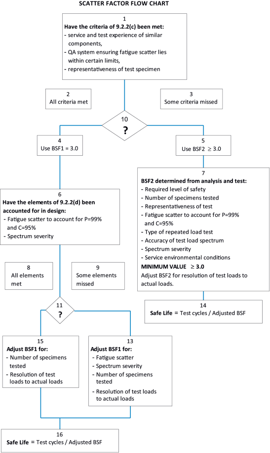
In the interpretation of fatigue analyses and test data the effect of variability should, under CS 25.571(c), be accounted for by an appropriate scatter factor. In this process it is appropriate that the applicant justifies the scatter factor chosen for any safe-life part. The following guidance is provided (see Figure 1):
(a) The base scatter factors (BSF) applicable to test results are: BSF1 = 3.0, and BSF2 = (see paragraph 9.2.2(e) of this AMC). If the applicant can meet the requirements of 9.2.2(c) of this AMC, he/she may use BSF1 or, at his/her option, BSF2.
(b) The base scatter factor, BSF1, is associated with test results of one representative test specimen.
(c) Justification for use of BSF1. BSF1 may only be used if the following criteria are met:
(i) Understanding of load paths and failure modes
Service and test experience of similar in-service components that were designed using similar design criteria and methods should demonstrate that the load paths and potential failure modes of the components are well understood.
(ii) Control of design, material, and manufacturing process quality
The applicant should demonstrate that his/her quality system (e.g. design, process control, and material standards) ensures the scatter in fatigue properties is controlled, and that the design of the fatigue-critical areas of the part account for the material scatter.
(iii) Representativeness of the test specimen
(A) The test article should be full scale (component or subcomponent) and represent that portion of the production aircraft requiring test. All differences between the test article and the production article should be accounted for either by analysis supported by test evidence, or by testing itself.
(B) Construction details, such as bracket attachments, clips, etc., should be accounted for, even though the items themselves may be non-loadbearing.
(C) Points of load application and reaction should accurately reflect those of the aircraft, ensure correct behaviour of the test article, and guard against uncharacteristic failures.
(D) Systems used to protect the structure against environmental degradation can have a negative effect on fatigue life, and therefore, should be included as part of the test article.
(d) Adjustments to base scatter factor BSF1. Having satisfied the criteria of paragraph 9.2.2(c), justifying the use of BSF1, the base value of 3.0 should be adjusted to account for the following considerations, as necessary, where not wholly taken into account by design analysis. As a result of the adjustments, the final scatter factor may be less than, equal to, or greater than 3.0.
(i) Material fatigue scatter. Material properties should be investigated up to a 99 % probability of survival and a 95 % level of confidence.
(ii) Spectrum severity. Test load spectrum should be derived based on a spectrum sensitive analysis accounting for variations in both utilisation (i.e. aircraft weight, cg, etc.) and occurrences/size of loads. The test load spectrum applied to the structure should be demonstrated to be conservative when compared to the expected usage in-service.
(iii) Number of representative test specimens. Well established statistical methods should be used that associate the number of items tested with the distribution chosen to obtain an adjustment to the base scatter factor.
(e) If the applicant cannot satisfy the intent of all of paragraph 9.2.2(c) of this AMC, BSF2 should be used.
(i) The applicant should propose scatter factor BSF2 based on careful consideration of the following issues: the required level of safety, the number of representative test specimens, how representative the test is, expected fatigue scatter, type of repeated load test, the accuracy of the test loads spectrum, spectrum severity, and the expected service environmental conditions.
(ii) In no case should the value of BSF2 be less than 3.0.
(f) Resolution of test loadings to actual loadings. The applicant may use a number of different approaches to reduce both the number of load cycles and the number of test set-ups required.
These include the following:
— spectrum blocking (i.e., a change in the spectrum load sequence to reduce the total number of test set-ups);
— high-load clipping (i.e., reduction of the highest spectrum loads to a level at which the beneficial effects of compression yield are reduced or eliminated); and
— low-load truncation (i.e., the removal of non-damaging load cycles to simplify the spectrum).
Due to the modifications to the flight-by-flight loading sequence, the applicant should propose either analytical or empirical approaches to quantify an adjustment to the number of test cycles which represents the difference between the test spectrum and the assumed flight-by-flight spectrum. In addition, an adjustment to the number of test cycles may be justified by raising or lowering the test load levels as long as appropriate data supports the applicant’s position. Other effects to be considered are different failure locations, different response to fretting conditions, temperature effects, etc. The analytical approach should use well-established methods or be supported by test evidence.
9.3. Replacement times
Replacement times should be established for parts with established safe-lives and should, under CS 25.571(a)(3), be included in the information prepared under CS 25.1529. These replacement times can be extended if additional data indicates an extension is warranted. Important factors which should be considered for such extensions include, but are not limited to, the following:
9.3.1. Comparison of original evaluation with service experience
9.3.2. Recorded load and stress data
Recorded load and stress data entails instrumenting aeroplanes in service to obtain a representative sampling of actual loads and stresses experienced.
The data to be measured includes airspeed, altitude and load factor versus time ; or airspeed, altitude and strain ranges versus time ; or similar data. This data, obtained by instrumenting aeroplanes in service, provides a basis for correlating the estimated loading spectrum with the actual service experience.
9.3.3. Additional analyses and tests
If additional test data and analyses based on repeated load tests of additional or surviving specimens are obtained, a re-evaluation of the established safe-life can be made.
9.3.4. Tests of parts removed from service
Repeated load tests of replaced parts can be utilised to re-evaluate the established safe-life. The tests should closely simulate service loading conditions.
Repeated load testing of parts removed from service is especially useful where recorded load data obtained in service are available since the actual loading experienced by the part prior to replacement is known.
9.3.5. Repair or rework of the structure
In some cases, repair or rework of the structure can gain further life.
9.4. Type design developments and changes
For design developments, or design changes, involving structural configurations similar to those of a design already shown to comply with the applicable provisions of CS 25.571(c), it might be possible to evaluate the variations in critical portions of the structure on a comparative basis. A typical example would be redesign of the landing gear structure for increased loads. This evaluation should involve analysis of the predicted stresses of the redesigned primary structure and correlation of the analysis with the analytical and test results used in showing compliance of the original design with CS 25.571(c).
10. DISCRETE SOURCE DAMAGE
(a) General
The purpose of this section is to establish EASA guidelines for the consistent selection of load conditions for residual strength substantiation in showing compliance with CS 25.571(e) and CS 25.903(d). The intent of these guidelines is to define, with a satisfactory level of confidence, the load conditions that will not be exceeded on the flight during which the specified incident of CS 25.571(e) or CS 25.903(d) occurs. In defining these load conditions, consideration has been given to the expected damage to the aeroplane, the anticipated response of the pilot at the time of the incident, and the actions of the pilot to avoid severe load environments for the remainder of the flight consistent with his/her knowledge that the aeroplane may be in a damaged state. Under CS 25.631 continued safe flight and landing is required following the bird impact. Following the guidance of this paragraph for assessing structural damage to any part whose failure or partial failure may prevent continued safe flight and landing is an acceptable means of compliance to CS 25.631.
(b) The maximum extent of immediately obvious damage from discrete sources (CS 25.571(e)) should be determined and the remaining structure shown, with an acceptable level of confidence, to have static strength for the maximum load (considered as ultimate load) expected during completion of the flight. For uncontained rotor failure addressed under the CS 25.903(d) requirements and for applicants following AMC 20-128A, likely structural damage may be assumed to be equivalent to that obtained by using the rotor burst model and associated trajectories defined in AMC 20-128A, paragraph 9.0 ‘Engine and APU Failure Model’. This assessment should also include an evaluation of the controllability of the aircraft in the event of damage to the flight control system.
(c) The loads considered as ultimate should not be less than those developed from the following:
(1) At the time of the occurrence:
(i) the maximum normal operating differential pressure including the external aerodynamic pressures during 1.0 g level flight, multiplied by a 1.1 factor, combined with 1.0 g flight loads;
(ii) starting from 1.0 g level flight at speeds up to Vc, any manoeuvre or any other flight path deviation caused by the specified incident of CS 25.571(e), taking into account any likely damage to the flight controls and pilot normal corrective action.
(2) For the continuation of the flight, the maximum appropriate cabin differential pressure (including the external aerodynamic pressure), combined with:
(i) 70 % of the limit flight manoeuvre loads as specified in CS 25.571(b) and, separately;
(ii) at the maximum operational speed, taking into account any appropriate reconfiguration and flight limitations, the 1.0 g loads plus incremental loads arising from application of 40 % of the limit gust velocity and turbulence intensities as specified in CS 25.341 at Vc.
(d) At any time, the aeroplane must be shown, by analysis, to be free from flutter and other aeroelastic instabilities up to the boundary of the aeroelastic stability envelope described in CS 25.629(b)(2) with any change in structural stiffness resulting from the incident, consistent with CS 25.629(d)(8), CS 25.571(e), and CS 25.903(d).
11. ESTABLISHING THE LOV AND MAINTENANCE ACTIONS TO PREVENT WFD
(a) Structural maintenance programme
Theoretically, if an aircraft is properly maintained it could be operated indefinitely. However, it should be noted that structural maintenance tasks for an aircraft are not constant with time. Typically, tasks are added to the maintenance programme as the aircraft ages. It is reasonable to expect then that confidence in the effectiveness of the current structural maintenance tasks may not, at some future point, be sufficient for continued operation.
Maintenance tasks for a particular aircraft can only be determined based on what is known about that aircraft model at any given time: from analyses, tests, service experience, and teardown inspections. Widespread fatigue damage is of particular concern because inspection methods cannot be relied on solely to ensure the continued airworthiness of aircraft indefinitely. When inspections are focused on details in small areas and have a high probability of detection, they may be used by themselves to ensure continued airworthiness, unless or until there are in-service findings. Based on findings, these inspections may need to be modified, and it may be necessary to modify or replace the structure rather than continue with the inspection alone.
When inspections examine multiple details over large areas for relatively small cracks, they should not be used by themselves. Instead, they should be used to supplement the modification or replacement of the structure. This is because it would be difficult to achieve the probability of detection required to allow inspection to be used indefinitely as a means to ensure continued operational safety.
To prevent WFD from occurring, the structure must, therefore, occasionally be modified or replaced. Establishing all the replacements and modifications required to operate the aircraft indefinitely is an unbounded problem. This problem is solved by establishing an LOV of the engineering data that supports the structural maintenance programme. All necessary modifications and replacements are required to be established to ensure continued airworthiness up to the LOV. See paragraph 11(f) for the steps to extend the LOV.
(b) Widespread fatigue damage
Structural fatigue damage is progressive. It begins as minute cracks, and those cracks grow under the action of repeated stresses. It can be due to normal operational conditions and design attributes, or to isolated incidents such as material defects, poor fabrication quality, or corrosion pits, dings, or scratches. Fatigue damage can occur locally, in small areas or structural design details, or globally. Global fatigue damage is general degradation of large areas of structure with similar structural details and stress levels. Global damage may occur within a single structural element, such as a single rivet line of a lap splice joining two large skin panels (multiple site damage). Or it may be found in multiple elements, such as adjacent frames or stringers (multiple element damage). Multiple site damage and multiple element damage cracks are typically too small initially to be reliably detected with normal inspection methods. Without intervention these cracks will grow, and eventually compromise the structural integrity of the aircraft in a condition known as widespread fatigue damage. Widespread fatigue damage is increasingly likely as the aircraft ages, and is certain to occur if the aircraft is operated long enough without any intervention.
(c) Steps for establishing an LOV
The LOV is established as an upper limit to aeroplane operation with the inspections and other procedures provided under CS 25.1529 and Appendix H. The LOV is required by CS 25.571(a)(3) and is established because of increased uncertainties in fatigue and damage tolerance assessment and the probable development of widespread fatigue damage associated with aeroplane operation past the limit.
To support the establishment of the LOV, the applicant must demonstrate by test evidence and analysis at a minimum, and, if available, service experience and teardown inspection results of high-time aircraft, that WFD is unlikely to occur in that aircraft up to the LOV.
The process for establishing an LOV involves four steps:
— identifying a ‘candidate LOV’;
— identifying WFD-susceptible structure;
— performing a WFD evaluation of all susceptible structure; and
— finalising the LOV and establishing necessary maintenance actions.
Step 1 — Candidate LOV
Any LOV can be valid as long as it has been demonstrated that the aircraft model will be free from WFD up to the LOV based on the aircraft's inherent fatigue characteristics and that any required maintenance actions are in place. Early in the certification process applicants typically establish design service goals or their equivalent and set a design service objective to have structure remain relatively free from cracking, up to the design service goal. A recommended approach sets the ‘candidate LOV’ equal to the design service goal. The final LOV would depend on both how well that design objective was met, and the applicant’s consideration of the economic impact of maintenance actions required to preclude WFD up to the final LOV.
Step 2 — Identify WFD-susceptible structure
The applicant should identify the structure that is susceptible to WFD to support post-fatigue test teardown inspections or residual strength testing necessary to demonstrate that WFD will not occur in the aircraft structure up to the LOV. Appendix 2 to AMC 20-20 provides examples and illustrations of structure where multiple site damage or multiple element damage has been documented. The list in Appendix 2 to AMC 20-20 is not meant to be inclusive of all structure that might be susceptible to WFD on any given aircraft model and it should only be used for general guidance. It should not be used to exclude any particular structure.
The applicant should do the following when developing the list of structure susceptible to WFD:
(1) Establish criteria that could be used for identifying what structure is susceptible to WFD based on the definitions of multiple site damage, multiple element damage, and WFD. For example, structural details and elements that are repeated over large areas and operate at the same stress levels are obvious candidates. The criteria should be part of the applicant’s compliance data.
(2) Provide supporting rationale for including and excluding specific structural areas. This should be part of the applicant’s compliance data.
(3) Identify the structure to a level of detail required to support post-test activities that the applicant will use to evaluate the residual strength capabilities of the structure. Structure is free from WFD if the residual strength meets or exceeds that required by CS 25.571(b). Therefore, post-test activities such as teardown inspections and residual strength tests must provide data that support the determination of strength.
— For teardown inspections, specific structural details (e.g. holes, radii, fillets, cut-outs) need to be identified.
— For residual strength testing, the identification at the component or subcomponent level (e.g. longitudinal skin splices) may be sufficient.
Step 3 — Evaluation of WFD-susceptible structure
Applicants must evaluate all susceptible structure identified in Step 2. Applicants must demonstrate, by full-scale fatigue test, evidence that WFD will not occur in the aircraft structure prior to the LOV. This demonstration typically entails full-scale fatigue testing, followed by teardown inspections and a quantitative evaluation of any finding or residual strength testing, or both. Additional guidance about full-scale fatigue test evidence is included in Appendix 2 to this AMC.
Step 4 — Finalise LOV
After all susceptible structure has been evaluated, finalise the LOV. The results of the evaluations performed in Step 3 will either demonstrate that the strength at the candidate LOV meets or exceeds the levels required by CS 25.571(b) or not. If it is demonstrated that the strength is equal to or greater than that required, the final LOV could be set to the candidate LOV without further evidence. If it is demonstrated that the strength is less than the required level, at least two outcomes are possible:
(1) The final LOV may be equal with the candidate LOV. However, this would result in maintenance actions, design changes, or both, maintenance actions and design changes, to support operation of aircraft up to LOV. For MSD/MED, the applicant may use damage tolerance-based inspections to supplement the replacement or modification required to preclude WFD when those inspections have been shown to be practical and reliable.
(2) The final LOV may be less than the candidate LOV. This could reduce the need for maintenance actions or making design changes.
Maintenance actions
In some cases maintenance actions may be necessary for an aircraft to reach its LOV. These maintenance actions could include inspections, modifications, replacements, or any combination thereof.
— For initial certification, these actions should be specified as airworthiness limitation items and incorporated into the ALS of the ICA.
— For post-certified aircraft, these actions should be specified as service information by the TCH or included in an updated ALS and may be mandated by Airworthiness Directives.
Design changes
The applicant may determine that developing design changes to prevent WFD in future production aircraft is to their advantage. The applicant must substantiate the design changes according to the guidance contained in this AMC
In addition to the technical considerations, the LOV may be influenced by several other factors, including:
— maintenance considerations;
— operator’s input; and
— economics.
(d) Airworthiness Limitations Section (ALS)
In accordance with Part-21 the TCH must provide the ICA (which includes the ALS) with the aircraft. However, the TCH may or may not have completed the full-scale fatigue test programme at the time of type certification.
Under CS 25.571, EASA may issue a type certificate for an aircraft model prior to the applicant’s completion of the full-scale fatigue testing, provided that EASA has agreed to the applicant’s plan for completing the required tests.
Until the full-scale fatigue testing is completed and EASA has approved the LOV, the applicant must establish a limitation that is equal to not more than one half of the number of cycles accumulated on the test article supporting the WFD evaluation. Under Appendix H to CS-25, the ALS must contain the limitation preventing operation of the aircraft beyond one half of the number of cycles accumulated on the fatigue test article approved under CS 25.571. This limitation is an airworthiness limitation. No aircraft may be operated beyond this limitation until fatigue testing is completed and an LOV is approved. As additional cycles on the fatigue test article are accumulated, this limitation may be adjusted accordingly. Upon completion of the full-scale fatigue test, applicants should perform specific inspections and analyses to determine whether WFD has occurred. Additional guidance on post-test WFD evaluations is included in Appendix 2 to this AMC.
At the time of type certification, the applicant should also show that at least one calendar year of safe operation has been substantiated by the fatigue test evidence agreed to be necessary to support other elements of the damage tolerance and safe-life substantiations. Some of these tests may require application of scatter factors greater than two resulting in more restrictive operating limitations on some parts of the structure.
After the full-scale fatigue test and the WFD evaluation have been completed, the applicant must include the following in the ALS:
— Under Appendix H to CS 25, the ALS must contain the LOV stated as a number of total accumulated flight cycles or flight hours approved under CS 25.571; and
— Depending on the results of the evaluation under Step 3 above, the ALS may also include requirements to inspect, modify or replace the structure.
(e) Repairs and type design changes
Any person applying for a change to a type certificate (TC) or a supplemental type certificate (STC) must demonstrate that any affected structure is free from WFD up to the LOV. (Note: It is possible that the STC applicant may generate a new LOV for the aeroplanes as part of the STC limitations).
Applicants for a major repair to the original aircraft or to an aircraft modified under a major change or an STC must demonstrate that any affected structure is free from WFD up to the LOV.
The evaluation should assess the susceptibility of the structure to WFD and, if it is susceptible, demonstrate that WFD will not occur prior to the LOV. If WFD is likely to occur before LOV is reached, the applicant must either:
(1) redesign the proposed repair to preclude WFD from occurring before the aircraft reaches the LOV; or
(2) develop maintenance actions to preclude WFD from occurring before the aircraft reaches the LOV; or
(3) for significant major changes and STCs only, establish a new LOV.
For repairs, the applicant must identify and include these actions as part of the repair. For major changes and STCs, the applicant must identify and include these actions as airworthiness limitation items in the ALS of the ICA. WFD evaluation is considered part of the fatigue and damage tolerance evaluation with respect to the three-stage repair approval process.
(f) Extended LOV
To extend an LOV, an application for a major change is required.
Typically, the data necessary to extend an LOV includes additional full-scale fatigue test evidence. The primary source of this test evidence should be full-scale fatigue testing. This testing should follow the guidance contained in Appendix 2 to this AMC.
[Amdt 25/19]
Appendix 1 – Crack growth analysis and tests
ED Decision 2017/015/R
Crack growth characteristics should be determined for each detail design point identified in accordance with 7(f) above. This information, when combined with the results from the residual strength analyses and tests, will be the basis for establishing the inspection requirements as discussed in Section 8. Crack growth characteristics can be determined by analysis or test. However, due to the large number of detail design points that are typically evaluated, and the practical limitations involved with testing, analyses are generally relied on to determine crack growth at the detail design point.
(a) Analyses. In order to perform a crack-growth analysis a number of key elements are needed. These include:
(1) a load/stress spectrum applicable to the detail design point;
(2) an initial crack size and shape to be assumed;
(3) a cracking scenario to be followed;
(4) applicable stress intensity solution(s);
(5) a crack growth algorithm; and
(6) material crack growth rate properties.
A loading spectrum must be developed for each detail design point. It is derived from the overall aircraft usage spectrum that is discussed in paragraph 6(b). The spectra at each detail design point may be modified for various reasons. The most common modification for metallic structure involves the deletion of high infrequent loads that may have an unrepresentative beneficial effect on crack growth if retardation is considered. Also, local load events that are not part of the overall aircraft spectrum should be included (e.g. flutter damper loads during pre-flight control surface checks).
The initial crack size and shape and subsequent cracking scenario to be followed are problem-dependent.
Applicable stress intensity solutions may be available in the public domain or may need to be developed. Many references exist which provide technical guidance for the application and development of stress intensity solutions. Care should be taken to ensure that the reference stress used for the spectrum load and stress intensity solution are compatible.
Crack-growth algorithms used in predicting crack extension range from simple linear models to complex ones that can account for crack growth retardation and acceleration. It is generally accepted that the use of a linear model will result in conservative results. A non-linear model, on the other hand, can be conservative or non-conservative and generally requires a higher level of validation and analysis/test correlation to adequately validate the accuracy of the algorithm. Coupon testing should be performed using representative materials and spectra types (e.g. wing lower cover, pylon support lug, horizontal-stabiliser upper cover) that will be encountered in the course of the overall aircraft crack-growth evaluation.
Crack growth rate data (e.g. da/dN vs ∆K vs R, da/dN vs ∆Keff) for many common aerospace materials is available in the public domain. Additionally, testing standards (e.g. ASTM) exist for performing tests to gather this data. The generally accepted practice is to use typical or average representation of this data for performing crack growth evaluations.
(b) Tests. Crack-growth testing using coupons is typically performed to generate crack growth rate data and to validate crack growth algorithms used for analyses. Simple specimens are generally used that have well-established stress intensity solutions for the characteristic cracking that can be expected. The primary issue for these tests is the pre-cracking required to achieve a well-behaved fatigue crack before data is collected. Effective pre-cracking procedures (e.g. ‘load shedding’) have been established and are described in the public domain. Care must be taken to ensure that subsequent crack growth is not affected by the prior pre-cracking.
In order to minimise the test time for actual structural components and/or full-scale test articles, the test loading spectrum may be modified by eliminating small magnitude load events or by replacing them with a fewer number of larger load events that give equivalent crack growth.
Crack-growth behaviour may be obtained from actual structural components and/or full-scale test articles. However, inducing active fatigue cracks of the desired initial size and at the desired locations can be extremely difficult. Past success in obtaining useful data has been achieved on an opportunistic basis when natural fatigue cracks have developed in the course of normal cyclic testing. Naturally occurring and artificially induced fatigue cracks may be monitored and data collected for at least a portion of the overall crack-growth period to be used for setting inspection requirements. This data can be extremely useful in supplementing and validating the analytical predictions, in some cases it may be the sole basis for the establishment of inspection requirements. Where fatigue test crack growth data is used, the results should be corrected to address expected operational conditions.
[Amdt 25/19]
Appendix 2 – Full-scale fatigue test evidence
ED Decision 2017/015/R
(a) Overview
CS 25.571(b) requires that special consideration for widespread fatigue damage (WFD) be included where the design is such that this type of damage could occur. This Appendix focuses on the test evidence in support of establishing the LOV and applicants will also need to consider and agree with EASA the extent of testing required in support of compliance with CS 25.571 in general, in particular for validation of hot spots, areas of complex loading exhibiting crack growth, single load path components, and safe-life items. CS 25.571(b) requires the effectiveness of the provisions to preclude the possibility of widespread fatigue damage occurring within the limits of validity of the structural maintenance programme to be demonstrated with sufficient full-scale fatigue test evidence. The determination of what constitutes ‘sufficient full-scale test evidence’ requires a considerable amount of engineering judgment and is a matter that should be discussed and agreed to between the applicant and EASA early in the planning stage for a certification project. In general, sufficient full-scale test evidence to support an LOV consists of full-scale fatigue testing to at least two times the LOV, followed by specific inspections and analyses to determine that widespread fatigue damage has not occurred. It may be appropriate to allow for three life times of testing, especially if inspection may not be practical for areas subject to WFD and requiring SMPs to be established. The following factors should be considered in determining the sufficiency of evidence:
Factor 1: The comparability of the load spectrum between the test and the projected usage of the aeroplane.
Factor 2: The comparability of the airframe materials, design and build standards between the test article and the certified aeroplane.
Factor 3: The extent of post-test teardown inspection, residual strength testing and analysis for determining if widespread fatigue cracking has occurred.
Factor 4: The duration of the fatigue testing.
Factor 5: The size and complexity of a design or build standard change. This factor applies to design changes made to a model that has already been certified and for which full-scale fatigue test evidence for the original structure should have already been determined to be sufficient. Small, simple design changes, comparable to the original structure, or changes that are derived from the original design using the same basic design configuration and where very similar load paths and similar operating stress levels are retained could be analytically determined to be equivalent to the original structure in their propensity for WFD. In such cases, additional full-scale fatigue test evidence should not be necessary.
Factor 6: In the case of major changes and STCs, the age of an aeroplane being modified. This factor applies to aeroplanes that have already accumulated a portion of their LOV prior to being modified. An applicant should only be required to demonstrate freedom from WFD up to the LOV in place for the original aeroplane.
(b) Elements of a full-scale fatigue test programme
The following guidance addresses elements of a test programme that is intended to generate the data necessary to support compliance. It is generally applicable to all certification projects.
(1) Article. The test article should be representative of the structure of the aircraft to be certified (i.e. ideally a production standard article). The attributes of the type design that could affect MSD/MED initiation, growth and subsequent residual strength capability should be replicated as closely as possible on the test article. Critical attributes include, but are not limited to, the following:
— material types and forms;
— dimensions;
— joining methods and details;
— coating and plating;
— use of faying surface sealant;
— assembly processes and sequences; and
— influence of secondary structure (e.g. loads induced due to proximity to the structure under evaluation).
(2) Test set-up and loading. The test set-up and loading should result in a realistic simulation of expected operational loads.
(i) Test set-up. The test set-up dictates how loads are introduced into the structure and reacted. Every effort should be made to introduce and react loads as realistically as possible. When a compromise is made (e.g. wing air loading), the resulting internal loads should be evaluated (e.g. using finite element methods) to ensure that the structure is not being unrealistically underloaded or overloaded locally or globally.
(ii) Test loading. The test loading spectrum should include loads from all damaging sources (e.g. cabin pressurisation, manoeuvers, gusts, engine thrust, control surface deflection, and landing impact) that are significant for the structure being evaluated. Supporting rationale should be provided when a source is not represented in a sequence. Additionally, differences between the test sequence and expected operational sequence should be justified. For example, it is standard practice to eliminate low loads that are considered to be non-damaging and clip high infrequent loads that may non-conservatively bias the outcome, but care should be taken in both cases so that the test results are representative. Paragraph 9.2.2(f) provides some guidance on justifying the test loading sequence.
(3) Test duration. AMC 20-20 includes guidance on how to establish mandatory maintenance actions for WFD-susceptible structure needed to preclude WFD occurrence in that structure. For any WFD-susceptible area the average time in flight cycles and/or hours to develop WFD must first be determined. This is referred to as the WFD average behaviour for the subject area. The AMC 20-20 guidance states that the area should be modified/replaced at one third of this time unless inspection for MSD/MED is practical. If inspection is practical the guidance states that inspection should start at one third of the WFD average behaviour with modification/replacement at one half of that time. It is standard practice to interpret the non-factored fatigue life of one specimen as the average life. It follows that if a full-scale fatigue test article survives a test duration of X without WFD occurrence, it can be conservatively assumed that the WFD average behaviour of all susceptible areas is equal to X. Based on this, and assuming that the susceptible areas are impractical to inspect for MSD/MED, the guidance of AMC 20-20 would require that replacement/modification would have to be implemented at X/3. For areas where MSD/MED inspections were practical replacement/modification could be deferred until X/2, but MSD/MED inspections would have to start at X/3. The preceding should be kept in mind when deciding what the test duration will be.
(4) Post-test evaluation. One of the primary objectives of the full-scale fatigue test is to generate data needed to determine the absolute WFD average behaviour for each susceptible area, or to establish a lower bound. Recall that the definition of WFD average behaviour is the average time required for MSD/MED to initiate and grow to the point that the static strength capability of the structure is reduced below the residual strength requirements of CS 25.571(b). Some work is required at the end of the test to determine the strength capability of the structure either directly or indirectly.
(i) Residual strength tests. One acceptable way to demonstrate freedom from WFD at the end of a full-scale fatigue test is to subject the article to the required residual strength loads specified in CS 25.571(b). If the test article sustains the loads it can be concluded that the point of WFD has yet to be reached for any areas. However, because fatigue cracks that might exist at the end of the test are not quantified it is not possible to determine how far beyond the test duration WFD would occur in any of the susceptible areas without accomplishing additional work (e.g. teardown inspection). Additionally, metallic test-articles may be non-conservatively compromised relative to their future fatigue performance if static loads in excess of representative operational loads are applied. Residual strength testing could preclude the possibility of using an article for additional fatigue testing.
(ii) Teardown inspections. The residual strength capability may be evaluated indirectly by performing teardown inspections to quantify the size of any MSD/MED cracks that might be present or to establish an upper bound on crack size based on inspection method capability. Once this is done the residual strength capability can be estimated analytically. Depending on the results crack-growth analyses may also be required to project backwards or forwards in time to estimate the WFD average behaviour for an area. As a minimum, teardown inspection methods should be capable of detecting the minimum size of MSD or MED cracking that would result in a WFD condition (i.e. residual strength degraded below the level specified in CS 25.571(b)). Ideally it is recommended that inspection methods be used that are capable of detecting MSD/MED cracking before it degrades strength below the required level. Effective teardown inspections required to demonstrate freedom from WFD typically require significant resources. They typically require disassembly (e.g. fastener removal) and destruction of the test article. All areas that are or may be susceptible to WFD should be identified and examined.
(c) Examples of fatigue test evidence for various types of certification projects.
The following examples offer some guidance on the types of data sets that might constitute ‘sufficient evidence’ for some kinds of certification projects. The scope of the test specimen and the duration of the test are considered.
(1) New type certificates. Normally this type of project would necessitate its own full-scale fatigue test of the complete airframe to represent the new structure and its loading environment. Nevertheless, prior to full-scale fatigue test evidence from earlier tests performed by the applicant, or others, may also be used and could supplement additional tests on the new model. Ultimately, the evidence needs to be sufficient to conclude with confidence that, within the LOV of the airframe, widespread fatigue damage will not occur. Factors 1 through 4 should be considered in determining the sufficiency of the evidence.
A test duration of a minimum of twice the LOV for the aeroplane model would normally be necessary if the loading spectrum is realistic, the design and construction for the test article principal structure is the same as for the certified aeroplane, and the post-test teardown is exhaustive. If the conformance to Factors 1 through 3 is less than ideal, a significantly longer test duration would be needed to conclude with confidence that WFD will not occur within the LOV. Moreover, no amount of fatigue testing will suffice if the conformance to Factors 1 through 3 above is not reasonable. Consideration should also be given to the possible future need for life extension or product development, such as potential weight increases, etc.
(2) Derivative models. The default position would be to test the entire airframe. However, it may be possible to reliably determine the occurrence of widespread fatigue damage for part or all of the derivative models from the data that the applicant generated or assembled during the original certification project. Nevertheless, the evidence needs to be sufficient to allow confidence in the calculations that show that widespread fatigue damage will not occur within the LOV of the aeroplane. Factors 1 through 5 should be considered in determining the sufficiency of the evidence for derivative models. For example, a change in the structural design concept, a change in the aerodynamic contour, or a modification of the structure that has a complex internal load distribution might well make analytical extrapolation from the existing full-scale fatigue test evidence very uncertain. Such changes might well necessitate full-scale fatigue testing of the actual derivative principal structure. On the other hand, a typical derivative often involves extending the fuselage by inserting ‘fuselage plugs’ that consist of a copy of the typical semi-monocoque construction for that model with slightly modified material gauges. Normally this type of project would not necessitate its own full-scale fatigue test, particularly if very similar load paths and operating stress levels are retained.
(3) Type design changes — Service bulletins. Normally this type of project would not necessitate the default option of a full-scale fatigue test because the applicant would have generated, or assembled, sufficient full-scale fatigue test evidence during the original certification project that could be applied to the change. Nevertheless, as cited in the previous example, the evidence needs to be sufficient to allow confidence in the calculations that show that widespread fatigue damage will not occur within the LOV of the aeroplane. In addition, Factor 5 ‘The size and complexity of a design change’ should be considered. Therefore, unless otherwise justified, based on existing test data or a demonstration that the design change is not susceptible to WFD, the applicant should perform full-scale tests for the types of design changes listed in Appendix 4.
(4) Supplemental type certificates (STCs)
Unless otherwise justified according to the guidance below or based on existing test data or a demonstration that the design change is not susceptible to WFD, the applicant for an STC should perform full-scale tests for the types of design changes listed in Appendix 4.
(i) Sufficient full-scale test evidence for structure certified under an STC may necessitate additional full-scale fatigue testing, although the extent of the design change may be small enough to use Factor 5 to establish the sufficiency of the existing full-scale fatigue test evidence. The applicant for an STC may not have access to the original equipment manufacturer’s full-scale fatigue test data. For aircraft types where an LOV has been published, the STC applicants may assume that the basic structure is free from WFD up to the LOV, unless:
— EASA has issued an airworthiness directive (AD), or intends to take such action (proposed AD), to alleviate a WFD condition; or
— inspections or modifications exist in the ALS relating to WFD conditions.
For the purpose of the STC applicant’s demonstration, it may be assumed that the aeroplane to which the LOV is applicable has received at least two full LOV of fatigue testing under realistic loads, and has received a thorough post-test inspection that either did not detect any WFD or the ALS includes from the outset details of modifications required to address WFD that will need specific consideration by the STC applicant. With this knowledge, and considering the Factors 1 through 5, the STC applicant may be able to demonstrate that WFD will not occur on its modification (or the underlying original structure) within the LOV or a suitably revised value. If, however, the modification significantly affects the distribution of stress in the underlying structure, or significantly alters loads in other parts of the aeroplane, or significantly alters the intended mission for the aeroplane, or, if the modification is significantly different in structural concept from the certified aeroplane being modified, additional representative fatigue test evidence would be necessary.
(ii) In addition, Factor 6 ‘The age of the aeroplane being modified’ could be considered for modifications made to older aeroplanes. The STC applicant should demonstrate freedom from WFD up to the LOV of the aeroplane being modified. For example, an applicant for an STC to an aeroplane that has reached an age equivalent to 75 % of its LOV should demonstrate that the modified aeroplane will be free from WFD for at least the remaining 25 % of the LOV. Although an applicant could attempt to demonstrate freedom from WFD for a longer period, this may not be possible unless the original equipment manufacturer cooperates by providing data for the basic structure. A short design service goal for the modification could simplify the demonstration of freedom from WFD for the STC applicant.
(5) Repairs. New repairs that differ from the repairs contained in the original equipment manufacturer’s structural repair manual, but that are equivalent in design to such repairs, and that meet CS-25 in other respects, would not necessitate full-scale fatigue testing to support freedom from WFD up to the LOV. Concerning major repair solutions (that may be susceptible to WFD) which utilise design concepts that are different from previous approved repair data (e.g. new materials, other production processes, new design details), further testing may be required.
(d) Use of existing full-scale fatigue test data
In some cases, especially for derivative models and type design changes accomplished by the type certificate holder, there may be existing full-scale fatigue test data that may be used to support compliance and mitigate the need to perform additional testing.
Any physical differences between the structure originally tested and the structure being considered that could affect its fatigue behaviour must be identified and reconciled. Differences that should be addressed include, but are not limited to, differences in any of the physical attributes listed under section (b)(1) of this Appendix and differences in operational loading. Typical developments that affect the applicability of the original LOV demonstration data are:
(1) gross weight (e.g. increases);
(2) cabin pressurisation (e.g. change in maximum cabin or operating altitude); and
(3) flight segment parameters.
The older the test data, the harder it may be to demonstrate that it is sufficient. Often test articles were not conformed, nor were test plans or reports submitted to EASA as part of the compliance data package. Loading sequence rigor varied significantly over the years and from applicant to applicant. Additionally, testing philosophies and protocols were not standardised. For example, post-test evaluations, if any, varied significantly and in some cases consisted of nothing more than limited visual inspections. However, there may be acceptable data from early full-scale fatigue tests that the applicant proposes to use to support compliance. In order to use such data the configuration of the test article and loading must be verified and the issue of the residual strength capability of the article (or teardown data) at the end of the test must be addressed.
(e) Use of in-service data. There may be in-service data that can be used to support WFD evaluations. Examples of such data are as follows:
— Documented positive findings of MSD/MED cracks that include location, size and the time in service of the affected aircraft along with a credible record of how the aircraft had been operated since original delivery.
— Documented negative findings from in-service inspections for MSD/MED cracks on a statistically significant number of aircraft with the time in service of each aircraft and a credible record of how each aircraft had been operated since original delivery. For this data to be useful, the inspections methods used should have been capable of detecting MSD/MED crack sizes equal to or smaller than those sizes that could reduce the strength of the structure below the residual strength levels specified in CS 25.571(b).
— Documented findings from the destructive teardown inspection of structure from in-service aircraft. This might be structure (e.g. fuselage splices) removed from aircraft that were subsequently returned to service, or from retired aircraft. It would also be necessary to have a credible record of the operational loading experienced by the subject structure up to the time it was taken out of service.
— Prior to using in-service data any physical and usage/loading differences that exist between the structure of the in-service or retired aircraft and the structure being certified should be identified and reconciled as discussed above.
[Amdt 25/19]
Appendix 3 – Methods for inspection threshold determination
ED Decision 2017/015/R
Different approaches have been used to calculate inspection thresholds, although these are essentially variants of one of two methods, being:
(a) the fatigue (stress-life or strain-life) method, which uses fatigue endurance data collected under constant stress or constant strain conditions, and a linear damage accumulation model (Palmgren-Miner rule);
(b) the crack growth method, which uses crack propagation and residual strength data to calculate the growth from an assumed initial crack size to a critical crack length, according to fracture mechanics principles.
CS 25.571(a)(4) requires certain types of structure to have thresholds based upon crack growth analyses or test assuming the maximum probable flaw due to manufacturing or service-induced damage. This approach applies to:
(a) single load path structure; and
(b) multiple load path ‘fail-safe’ structure and crack arrest ‘fail-safe’ structure, where it cannot be demonstrated that the resulting load path failure or partial failure (including arrested cracks) will be safely detected and repaired during normal maintenance, inspection, or operation of an aeroplane prior to failure of the remaining structure.
Paragraph 8(c) of this AMC provides further details on identifying this structure.
In lieu of other data, an acceptable threshold for inspection for cracks emanating from the maximum probable manufacturing flaw at a fastener hole may be obtained for aluminium alloy airframe structure if an initial corner crack of radius 0.05’’ (1.27 mm) is assumed and the total crack growth life is divided by 2. Whether this approach is also sufficient to conservatively address all probable forms of manufacturing and service-induced damage needs careful consideration and is highly design dependent. Where specific test or service data for service damage exists that can be used to reliably establish an appropriate threshold for all likely types of service damage then crack growth analysis may only need to consider the manufacturing flaw.
For structure susceptible to WFD specific methods for setting inspection thresholds are applicable when agreed to be practical; see Section 11 and Appendix 2 to this AMC.
Regardless of the approach used, the calculated thresholds should be supported with appropriate fatigue test evidence. The best sources of fatigue test evidence are from service experience and large component or full-scale fatigue tests. Large component and full-scale fatigue test specimens are generally constructed using the same manufacturing processes as on the actual aircraft. The results of such tests should provide sufficient information to reliably establish the typical manufacturing quality and possibly its lower bound, especially when those results are combined with service experience. Conversely, simple test specimens used to generate fatigue endurance and crack growth data, which are typically assembled under laboratory or workshop conditions, may not be representative of the actual range of manufacturing quality in the structure under consideration. Therefore, in the absence of information from the full-scale fatigue tests and service experience, consideration should be given to generating fatigue endurance and crack growth data on simple test specimens which include artificial damages that are introduced at the beginning of the test, and are representative of the lower bound of manufacturing quality.
[Amdt 25/19]
Appendix 4 – Examples of changes that may require full-scale fatigue testing
ED Decision 2017/015/R
The following are examples of types of modifications that may require full-scale fatigue testing:
(1) passenger-to-freighter conversions (including addition of cargo doors);
(2) gross weight increases (e.g. increased operating weights, increased zero-fuel weights, increased landing weights, and increased maximum take-off weights);
(3) installation of fuselage cut-outs (e.g. passenger entry doors, emergency exit doors or crew escape hatches, fuselage access doors, and cabin window relocations);
(4) complete re-engine or pylon change;
(5) engine hush kits;
(6) wing modifications (e.g. installation of winglets, changes in flight-control settings such as flap droop, and change of wing trailing-edge structure);
(7) modified or replaced skin splice;
(8) any modification that affects three or more stiffening members (e.g. wing stringers and fuselage frames);
(9) a modification that results in operational-mission change, which significantly changes the original equipment manufacturer’s load/stress spectrum (e.g. extending the flight duration from 2 hours to 10 hours); and
(10) a modification that changes areas of the fuselage from being externally inspectable using visual means to being non-inspectable (e.g. installation of a large, external fuselage doubler that results in hiding details beneath it).
[Amdt 25/19]
Appendix 5 – PSE, FCS, and WFD-susceptible structure
ED Decision 2017/015/R
(a) Overview
Four key terms used when showing compliance to the damage tolerance and fatigue requirements of CS-25 and EASA guidance for the continued structural integrity of ageing aircraft in AMC 20-20 are: ‘principle structural element (PSE)’, ‘fatigue critical structure (FCS)’, ‘widespread fatigue damage (WFD)-susceptible structure’ and ‘design detail point (DDP)’.
This Appendix provides clarification on the intended meanings of these terms and how they relate to each other.
(b) Principal structural element (PSE)
(1) The term ‘principal structural element (PSE)’ is defined in this AMC as follows:
‘Principal structural element (PSE)’ is an element that contributes significantly to the carrying of flight, ground or pressurisation loads, and whose integrity is essential in maintaining the overall structural integrity of the aeroplane.
(2) While this definition does not specifically address the fatigue susceptibility of the structure, or environmental or accidental damage, it is intended to address the majority of the structure that must be evaluated according to CS 25.571. CS 25.571(a) states the following:
‘This evaluation must be conducted for each part of the structure that could contribute to a catastrophic failure’.
(3) Examples of PSEs are found in paragraph 7(f) of this AMC.
(4) The above reinforces the notion that the identification of PSEs should be based solely on the importance of the structure to assure the overall aeroplane integrity.
(5) Paragraph 7(f) of this AMC provides guidance for identifying PSEs. Many manufacturers use this list as a starting point for their list of Fatigue Critical Structure (FCS). CS 25.571(b) is intended to address all structure that could contribute to a catastrophic failure resulting from fatigue, environmental and accidental damage, and, therefore, may include some structure that is not considered FCS. Nevertheless, all PSE should be considered when developing a list of FCS.
(6) The definitions used by applicants to identify PSEs have not been consistent among applicants and, in some cases, among models produced by the same applicant. The lack of standardisation of the usage and understanding of the term ‘PSE,’ and the resulting diversity that exists between type design PSE lists, led authorities to introduce the new term ‘Fatigue Critical Structure (FCS)’ in the ‘Ageing Aircraft Requirements and Guidance Material’.
(c) Fatigue Critical Structure (FCS)
(1) ‘Fatigue critical structure (FCS)’ is defined as aircraft structure that is susceptible to fatigue cracking, which could contribute to a catastrophic failure. Fatigue critical structure also includes structure which, if repaired or modified, could be susceptible to fatigue cracking and contribute to a catastrophic failure. Structure is most often susceptible to fatigue cracking when subjected to tension-dominated repeated loads during operation. Such structure may be part of the baseline structure or part of a modification. ‘baseline structure’ means structure that is designed under the original type certificate or amended type certificate for that aircraft model (i.e. the as-delivered-aeroplane model configuration).
(2) Fatigue critical structure is generally a subset of principal structural elements, specifically those elements that are susceptible to fatigue damage. The exception may be a DDP that is susceptible to fatigue and, although not part of a PSE, could result in catastrophic failure if it were to fail (e.g. an undercarriage door hinge has been categorised by some TCHs as a DDP and FCS, when its failure would lead to loss of the door and the door could impact the aircraft with catastrophic results. In this case the door was not classified as a PSE because the TCH had not considered the door to contribute significantly to carrying flight, ground or pressurisation loads. Considering further aspects of the PSE definition now adopted, it might be claimed that the door is not essential to maintain the overall integrity of the aircraft, i.e. the aircraft may be safe without it. However, due to the need to identify all detail design points and FCS whose failure could cause catastrophic failure of the aircraft it is in any case subject to the fatigue and damage tolerance requirements.)
(d) Detail design points (DDP)
‘Detail design point’ is an area of structure that contributes to the susceptibility of the structure to fatigue cracking or degradation such that the structure cannot maintain its load carrying capability, which could lead to a catastrophic failure.
(e) Widespread fatigue damage (WFD)-susceptible structure
(1) ‘Widespread fatigue damage (WFD)’ is the simultaneous presence of cracks at multiple structural locations, which are of sufficient size and density such that the structure no longer meets the residual strength requirements of CS 25.571(b).
(2) ‘Multiple site damage (MSD)’ and ‘Multiple element damage (MED)’ are conditions that, with no intervention, can lead to WFD. The term ‘WFD-susceptible structure’ refers to areas of structure that, under normal circumstances, could be expected to eventually develop MSD and/or MED cracks, which could lead to WFD.
(3) Although not explicitly stated, structure susceptible to WFD cannot be inspected reliably to preclude WFD. Unless a flight cycles and/or flight hours limit is placed on an aeroplane, modifications may be needed to preclude WFD. Structure susceptible to WFD is a subset of FCS.
[Amdt 25/19]