
ED Decision 2007/010/R
(See AMC 25.963(d))
(a) The landing gear system must be designed so that when it fails due to overloads during take-off and landing, the failure mode is not likely to cause spillage of enough fuel to constitute a fire hazard. The overloads must be assumed to act in the upward and aft directions in combination with side loads acting inboard and outboard. In the absence of a more rational analysis, the side loads must be assumed to be up to 20% of the vertical load or 20% of the drag load, whichever is greater.
(b) The aeroplane must be designed to avoid any rupture leading to the spillage of enough fuel to constitute a fire hazard as a result of a wheels-up landing on a paved runway, under the following minor crash landing conditions:
(1) Impact at 1.52 m/s (5 fps) vertical velocity, with the aeroplane under control, at Maximum Design Landing Weight,
(i) with the landing gear fully retracted and, as separate conditions,
(ii) with any other combination of landing gear legs not extended.
(2) Sliding on the ground, with -
(i) the landing gear fully retracted and with up to a 20° yaw angle and, as separate conditions,
(ii) any other combination of landing gear legs not extended and with 0° yaw angle.
(c) For configurations where the engine nacelle is likely to come into contact with the ground, the engine pylon or engine mounting must be designed so that when it fails due to overloads (assuming the overloads to act predominantly in the upward direction and separately predominantly in the aft direction), the failure mode is not likely to cause the spillage of enough fuel to constitute a fire hazard.
[Amdt 25/3]
CS 25.723 Shock absorption tests
ED Decision 2003/2/RM
(See AMC 25.723)
(a) The analytical representation of the landing gear dynamic characteristics that is used in determining the landing loads must be validated by energy absorption tests. A range of tests must be conducted to ensure that the analytical representation is valid for the design conditions specified in CS 25.473.
(1) The configurations subjected to energy absorption tests at limit design conditions must include at least the design landing weight or the design takeoff weight, whichever produces the greater value of landing impact energy.
(2) The test attitude of the landing gear unit and the application of appropriate drag loads during the test must simulate the aeroplane landing conditions in a manner consistent with the development of rational or conservative limit loads.
(b) The landing gear may not fail in a test, demonstrating its reserve energy absorption capacity, simulating a descent velocity of 3.7 m/s (12 fps) at design landing weight, assuming aeroplane lift not greater than the aeroplane weight acting during the landing impact.
(c) In lieu of the tests prescribed in this paragraph, changes in previously approved design weights and minor changes in design may be substantiated by analyses based on previous tests conducted on the same basic landing gear system that has similar energy absorption characteristics.
AMC 25.723 Shock absorption tests
ED Decision 2006/005/R
1. PURPOSE. This AMC sets forth an acceptable means, but not the only means, of demonstrating compliance with the provisions of CS-25 related to the use of landing gear shock absorption tests and analyses to determine landing loads for large aeroplanes.
2. RELATED CERTIFICATION SPECIFICATIONS. CS 25.723 "Shock absorption tests" and CS 25.473 "Landing load conditions and assumptions."
3. SHOCK ABSORPTION TESTS.
a. Validation of the landing gear characteristics. Shock absorption tests are necessary to validate the analytical representation of the dynamic characteristics of the landing gear unit that will be used to determine the landing loads. A range of tests should be conducted to ensure that the analytical model is valid for all design conditions. In addition, consideration should be given to ensuring that the range of test configurations is sufficient for justifying the use of the analytical model for foreseeable future growth versions of the aeroplane.
b. Recommended test conditions for new landing gear units. The design takeoff weight and the design landing weight conditions should both be included as configurations subjected to energy absorption tests. However, in cases where the manufacturer has supporting data from previous experience in validating the analytical model using landing gear units of similar design concept, it may be sufficient to conduct tests of the new landing gear at only the condition associated with maximum energy. The landing gear used to provide the supporting data may be from another model aircraft but should be of approximately the same size with similar components.
c. Changes to type designs. CS 25.723(c) allows changes in previously approved design weights and minor changes in design to be substantiated by analyses based on tests of the same basic landing gear unit with similar energy absorption characteristics.
A landing gear unit would be considered to be of “the same basic landing gear system” when the design concept has not been changed. “Similar energy absorption characteristics” means that the changes to the landing gear unit, either taken individually or as a whole, would not have a significant effect on the validation of the analytical results for the modified aeroplane. Changes that may be acceptable without further energy absorption tests include minor changes and adjustments incorporated in the landing gear unit to maintain similar energy absorption characteristics with changes in design weight and landing speeds.
For example, the following changes may be acceptable without further tests:
(1) Minor changes in shock absorber details including pre-load, compression ratio, orifice sizes, metering pin profiles.
(2) Minor changes in tyre characteristics.
(3) Minor changes in unsprung mass (e.g. brakes).
(4) Local strengthening or minor sizing changes to the landing gear.
To allow justification by analysis for the reserve energy requirement, neither the shock strut nor the tyres should bottom during the reserve energy analysis or the tests upon which the analysis is correlated.
4. LIMIT FREE DROP TESTS.
a. Compliance with CS 25.723(a) may be shown by free drop tests, provided they are made on the complete aeroplane, or on units consisting of a wheel, tyre, and shock absorber, in their proper positions, from free drop heights not less than--
(1) 475 mm (18.7 inches) for the design landing weight conditions; and
(2) 170 mm (6.7 inches) for the design takeoff weight conditions.
b. If aeroplane lift is simulated by air cylinders or by other mechanical means, the weight used for the drop must be equal to W. If the effect of aeroplane lift is represented in free drop tests by a reduced weight, the landing gear must be dropped with an effective weight equal to
![]()
where:
We = the effective weight to be used in the drop test (kg);
h = specified free drop height (mm);
d = deflection under impact of the tyre (at the approved inflation pressure) plus the vertical component of the axle travel relative to the drop weight (mm);
W = WM for main gear units (kg), equal to the static weight on that unit with the aeroplane in the level attitude (with the nose wheel clear in the case of nose wheel type aeroplanes);
W = WT for tail gear units (kg), equal to the static weight on the tail unit with the aeroplane in the tail-down attitude;
W = WN for nose wheel units (kg), equal to the vertical component of the static reaction that would exist at the nose wheel, assuming that the mass of the aeroplane acts at the centre of gravity and exerts a force of 1.0 g downward and 0.25 g forward; and
L = ratio of the assumed aeroplane lift to the aeroplane weight, but not more than 1.0.
c. The drop test attitude of the landing gear unit and the application of appropriate drag loads during the test must simulate the aeroplane landing conditions in a manner consistent with the development of rational or conservative limit loads.
d. The value of d used in the computation of We in paragraph 4.(b) of this AMC may not exceed the value actually obtained in the drop test.
5. RESERVE ENERGY FREE DROP TESTS.
a. Compliance with the reserve energy absorption condition specified in CS 25.723(b) may be shown by free drop tests provided the drop height is not less than 69 cm (27 inches).
b. If aeroplane lift is simulated by air cylinders or by other mechanical means, the weight used for the drop must be equal to W. If the effect of aeroplane lift is represented in free drop tests by an equivalent reduced weight, the landing gear must be dropped with an effective weight:
![]()
where the symbols and other details are the same as in paragraph 4 above.
[Amdt 25/2]
CS 25.729 Extending and retracting mechanisms
ED Decision 2016/010/R
(See AMC 25.729)
(a) General. For aeroplanes with retractable landing gear, the following apply:
(1) The landing gear extending and retracting mechanisms, wheel well doors, and supporting structure, must be designed for –:
(i) the loads occurring in the flight conditions when the gear is in the retracted position;
(ii) the combination of friction loads, inertia loads, brake torque loads, air loads, and gyroscopic loads resulting from the wheels rotating at a peripheral speed equal to 1·23 VSR (with the flaps in takeoff position at design take-off weight), occurring during retraction and extension at any airspeed up to 1·5 VSR1 with the wing-flaps in the approach position at design landing weight, and
(iii) any load factor up to those specified in CS 25.345(a) for the wing-flaps extended condition.
(2) Unless there are other means to decelerate the aeroplane in flight at this speed, the landing gear, the extending and retracting mechanisms, and the aeroplane structure (including wheel well doors) must be designed to withstand the flight loads occurring with the landing gear in the extended position at any speed up to 0·67 VC.
(3) Landing gear doors, their operating mechanism, and their supporting structures must be designed for the yawing manoeuvres prescribed for the aeroplane in addition to the conditions of airspeed and load factor prescribed in sub-paragraphs (a)(1) and (2) of this paragraph.
(b) Landing gear lock. There must be positive means to keep the landing gear extended in flight and on the ground. There must be positive means to keep the landing gear and doors in the correct retracted position in flight, unless it can be shown that lowering of the landing gear or doors, or flight with the landing gear or doors extended, at any speed, is not hazardous.
(c) Emergency operation. There must be an emergency means for extending the landing gear in the event of –
(1) any reasonably probable failure in the normal extension and retraction systems; or
(2) the failure of any single source of hydraulic, electric, or equivalent energy supply.
(d) Operation test. The proper functioning of the extending and retracting mechanisms must be shown by operation tests.
(e) Position indicator and warning device. If a retractable landing gear is used, there must be a landing gear position indicator easily visible to the pilot or to the appropriate crew members (as well as necessary devices to actuate the indicator) to indicate without ambiguity that the retractable units and their associated doors are secured in the extended (or retracted) position. The means must be designed as follows:
(1) If switches are used, they must be located and coupled to the landing gear mechanical systems in a manner that prevents an erroneous indication of ‘down and locked’ if the landing gear is not in a fully extended position, or of ‘up and locked’ if the landing gear is not in the fully retracted position. The switches may be located where they are operated by the actual landing gear locking latch or device.
(2) The flight crew must be given an aural warning that functions continuously, or is periodically repeated, if a landing is attempted when the landing gear is not locked down.
(3) The warning must be given in sufficient time to allow the landing gear to be locked down or a go-around to be made.
(4) There must not be a manual shut-off means readily available to the flight crew for the warning required by sub-paragraph (e)(2) of this paragraph such that it could be operated instinctively, inadvertently or by habitual reflexive action.
(5) The system used to generate the aural warning must be designed to minimise false or inappropriate alerts.
(6) Failures of systems used to inhibit the landing gear aural warning, that would prevent the warning system from operating, must be improbable.
(7) A clear indication or warning must be provided whenever the landing gear position is not consistent with the landing gear selector lever position.
[Amdt 25/4]
[Amdt 25/14]
[Amdt 25/18]
AMC 25.729 Extending retracting mechanisms
ED Decision 2016/010/R
1. PURPOSE. This Acceptable Means of Compliance (AMC) provides guidance material for use as an acceptable means of demonstrating compliance with the landing gear retracting mechanism requirements of the Certification Specification (CS) for large aeroplanes.
2. RELATED DOCUMENTS.
a. Related Certification Specifications. CS 25.729 and other paragraphs relating to landing gear extending and retracting mechanisms installations together with their applicable AMCs, if any. Paragraphs which prescribe requirements for the design, substantiation, and certification of landing gear extending and retracting mechanisms include:
CS 25.111 Take-off path
CS 25.301 Loads
CS25.303 Factor of safety
CS 25.305 Strength and deformation
CS 25.307 Proof of structure
CS 25.333 Flight envelope
CS 25.471 General [Ground loads]
CS 25.561 General [Emergency Landing Conditions]
CS 25.601 General [Design and Construction]
CS 25.603 Materials
CS 25.605 Fabrication methods
CS 25.607 Fasteners
CS 25.609 Protection of structure
CS 25.613 Material strength properties
CS 25.619 Special factors
CS 25.621 Casting factors
CS 25.623 Bearing factors
CS 25.625 Fitting factors
CS 25.729 Extending and retracting mechanisms
CS 25.777 Cockpit controls
CS 25.779 Motion and effect of cockpit controls
CS 25.781 Cockpit control knob shape
CS 25.863 Flammable fluid fire protection
CS 25.869 Fire protection: systems
CS 25.899 Electrical bonding, etc.
CS 25.1301 Function and installation
CS 25.1309 Equipment, systems and installations
CS 25.1315 Negative acceleration
CS 25.1316 System lightning protection
CS 25.1322 Warning, caution and advisory lights
CS 25.1353 Electrical equipment and installations
CS 25.1357 Circuit protective devices
CS 25.1360 Precautions against injury
CS 25.1435 Hydraulic systems
CS 25.1515 Landing gear speeds
CS 25.1555 Control markings
CS 25.1583 Operating limitations
CS 25.1585 Operating procedures
b. FAA Advisory Circulars (AC's).
AC 20-34D Prevention of Retractable Landing Gear Failures
AC 23-17B Systems and Equipment Guide for Certification of Part 23 Airplanes and Airships
AC 25.1309-1A System Design and Analysis
AC 25-7C Flight Test Guide for Certification of Transport Category Airplanes
AC 25-22 Certification of Transport Airplane Mechanical Systems
AC 43.13-1B Acceptable Methods, Techniques and Practices - Aircraft Inspection and Repair.
c. Federal Aviation Administration Orders.
Order 8110.4C Type Certification Process
Advisory Circulars and FAA Orders can be obtained from the U.S. Department of Transportation, Subsequent Distribution Office, SVC-121.23, Ardmore East Business Center, 3341 Q 75th Avenue, Landover, MD 20785.
d. Society of Automotive Engineers (SAE) Documents.
SAE AIR-4566 Crashworthiness Landing Gear Design
SAE ARP-1311A Landing Gear - Aircraft
ISO 7137 Environmental Conditions and Test Procedures for Airborne Equipment (not an SAE document but is available from the SAE)
These documents can be obtained from the Society of Automotive Engineers, Inc., 400 Commonwealth Drive, Warrendale, Pennsylvania, 15096.
e. Industry Documents.
(1) EUROCAE ED-14G/RTCA, Inc., Document No. DO-160G,
Environmental Conditions and Test Procedures for Airborne Equipment.
(2) AMC 20-115, Software Considerations in Airborne Systems and Equipment Certification.
These documents can be obtained from EUROCAE, 17 rue Hamelin, 75783 Paris Cedex 15, France
f. Military Documents.
MIL-STD-810 Environmental Test Methods and Engineering Guidelines
This document can be obtained from the Department of Defence, DODSSP, Standardisation Document Order Desk, 700 Robbins Avenue, Building 4D, Philadelphia, PA 19111-5094.
4. DISCUSSION.
a. Intent of rule. (Reference CS 25.729 Extending and retracting mechanisms)
This rule provides minimum design and certification requirements for landing gear actuation systems to address:
(1) Structural integrity for the nose and main landing gear, extending and retracting mechanism(s), doors, gear supporting structure for loads imposed during flight;
(2) Positive locking of the kinematic mechanisms;
(3) Redundant means of extending the landing gear;
(4) Demonstration of proper operation by test;
(5) Gear up-and-locked and down-and-locked position indications and aural warning;
(6) Equipment damage from tyre burst, loose tread, and wheel brake temperatures.
b. Demonstration of extending and retracting mechanisms proper functioning. (Reference CS 25.729(d) Operation test)
Guidance addressing flight testing used to demonstrate compliance with this paragraph may be found in FAA Advisory Circular (AC) 25-7C, Flight Test Guide for Transport Category Aeroplanes, Chapter 4, Section 4, paragraph 52, dated 16 October 2012.
c. Extending and retracting mechanisms indication. (Reference CS 25.729(e) Position indicator and warning device)
(1) When light indicators are used, they should be arranged so that-
(i) A green light for each unit is illuminated only when the unit is secured in the correct landing position.
(ii) A warning light consistent with CS 25.1322 is illuminated at all times except when the landing gear and its doors are secured in the landing or retracted position.
(2) The warning required by CS 25.729(e)(2) should preferably operate whatever the position of wing leading- or trailing-edge devices or the number of engines operating.
(3) The design should be such that nuisance activation of the warning is minimised, for example-
(i) When the landing gear is retracted after a take-off following an engine failure, or during a take-off when a common flap setting is used for take-off and landing;
(ii) When the throttles are closed in a normal descent; or
(iii) When flying at low altitude in clean or low speed configuration (special operation).
(4) Inhibition of the warning above a safe altitude out of final approach phase either automatically or by some other means to prevent these situations is acceptable, but it should automatically reset for a further approach.
(5) Means to de-activate the warning required by CS 25.729(e) may be installed for use in abnormal or emergency conditions provided that it is not readily available to the flight crew, i.e. the control device is protected against inadvertent actuation by the flight crew and its de-activated state is obvious to the flight crew.
d. Definitions. For definitions of VSR and VC, see CS-Definitions Chapter 2, entitled 'Abbreviations and symbols'.
[Amdt 25/4]
[Amdt 25/12]
[Amdt 25/14]
[Amdt 25/18]
ED Decision 2003/2/RM
(a) Each main and nose wheel must be approved.
(b) The maximum static load rating of each wheel may not be less than the corresponding static ground reaction with –
(1) Design maximum weight; and
(2) Critical centre of gravity.
(c) The maximum limit load rating of each wheel must equal or exceed the maximum radial limit load determined under the applicable ground load requirements of this CS-25.
(d) Overpressure burst prevention. Means must be provided in each wheel to prevent wheel failure and tyre burst that may result from excessive pressurisation of the wheel and tyre assembly.
(e) Braked wheels. Each braked wheel must meet the applicable requirements of CS 25.735.
ED Decision 2020/024/R
(a) When a landing gear axle is fitted with a single wheel and tyre assembly, the wheel must be fitted with a suitable tyre of proper fit with a speed rating approved by the Agency that is not exceeded under critical conditions, and with a load rating approved by the Agency that is not exceeded under –
(1) The loads on the main wheel tyre, corresponding to the most critical combination of aeroplane weight (up to the maximum weight) and centre of gravity position; and
(2) The loads corresponding to the ground reactions in sub-paragraph (b) of this paragraph, on the nose-wheel tyre, except as provided in sub-paragraphs (b)(2) and (b)(3) of this paragraph.
(b) The applicable ground reactions for nosewheel tyres are as follows:
(1) The static ground reaction for the tyre corresponding to the most critical combination of aeroplane weight (up to maximum ramp weight) and centre of gravity position with a force of 1·0 g acting downward at the centre of gravity. This load may not exceed the load rating of the tyre.
(2) The ground reaction of the tyre corresponding to the most critical combination of aeroplane weight (up to maximum landing weight) and centre of gravity position combined with forces of 1·0 g downward and 0·31 g forward acting at the centre of gravity. The reactions in this case must be distributed to the nose and main wheels by the principles of static’s with a drag reaction equal to 0·31 times the vertical load at each wheel with brakes capable of producing this ground reaction. This nose tyre load may not exceed 1·5 times the load rating of the tyre.
(3) The ground reaction of the tyre corresponding to the most critical combination of aeroplane weight (up to maximum ramp weight) and centre of gravity position combined with forces of 1·0 g downward and 0·20 g forward acting at the centre of gravity. The reactions in this case must be distributed to the nose and main wheels by the principles of static’s with a drag reaction equal to 0·20 times the vertical load at each wheel with brakes capable of producing this ground reaction. This nose tyre load may not exceed 1·5 times the load rating of the tyre.
(c) When a landing gear axle is fitted with more than one wheel and tyre assembly, such as dual or dual-tandem, each wheel must be fitted with a suitable tyre of proper fit with a speed rating approved by the Agency that is not exceeded under critical conditions, and with a load rating approved by the Agency that is not exceeded by –
(1) The loads on each main wheel tyre, corresponding to the most critical combination of aeroplane weight (up to maximum weight) and centre of gravity position, when multiplied by a factor of 1·07; and
(2) Loads specified in sub-paragraphs (a)(2), (b)(1), (b)(2) and (b)(3) of this paragraph on each nose-wheel tyre.
(d) Each tyre installed on a retractable landing gear system must, at the maximum size of the tyre type expected in service, have a clearance to surrounding structure and systems that is adequate to prevent unintended contact between the tyre and any part of the structure or systems.
(e) For an aeroplane with a maximum certificated take-off weight of more than 34019 kg (75 000 pounds), tyres mounted on braked wheels must be inflated with dry nitrogen or other gases shown to be inert so that the gas mixture in the tyre does not contain oxygen in excess of 5% by volume, unless it can be shown that the tyre liner material will not produce a volatile gas when heated, or that means are provided to prevent tyre temperatures from reaching unsafe levels.
(f) A means shall be provided to minimise the risk that a tyre is below its minimum serviceable inflation pressure during operation. (See AMC 25.733(f))
AMC 25.733(f) Tyre inflation pressure check
ED Decision 2020/024/R
1. General
‘Minimum serviceable inflation pressure’ means a tyre inflation pressure specified by the aeroplane type certificate holder below which damage to the tyre, potentially leading to a tyre failure, may occur.
In order to demonstrate compliance with CS 25.733(f), the applicant should use one, or a combination, of the following means:
(a) Provide a task in the Instructions for Continued Airworthiness (ICA) that requires tyres inflation pressure checks to be performed at a suitable time interval,
(b) Install a system that monitors the tyres inflation pressures and:
(1) provides an alert to the flight crew, in compliance with CS 25.1322, whenever a tyre inflation pressure is below the minimum serviceable inflation pressure, or
(2) allows the tyres inflation pressures to be checked prior to the dispatch of the aeroplane, and a tyre inflation pressure check task is included in the Aeroplane Flight Manual (AFM) pre-flight procedures.
2. ICA Tyre inflation pressure check
A ‘suitable time interval’ is the maximum time interval between two consecutive tyre inflation pressure checks.
Checks should be conducted daily in order to ensure that the elapsed clock time between two consecutive tyre inflation pressure checks does not exceed 48 hours.
Time intervals longer than 48 hours may be used if they are substantiated and agreed by EASA. This substantiation should at least include an analysis of the expected loss of tyre pressure during operation, taking into account the environmental and operational factors, including the potential for pressure loss at a rate that exceeds the normal diffusion resulting from damage to or degradation of the tyre/wheel assembly. If available, statistical data related to pressure losses gathered from the service experience of aeroplanes equipped with equivalent wheel designs should also be used. The substantiation should be made in cooperation with the tyre manufacturer(s). In addition, the applicant may take credit from an installed system monitoring the tyre inflation pressures.
3. Tyre inflation pressure monitoring systems
If a system is installed, its development assurance level should be commensurate with the potential consequences of an alert not being provided, as well as with the consequences of false alerts. If the system includes the indication of tyre pressure levels, the consequence of a false indication should also be taken into account. The assessment of these consequences should include the effects of the failure of one or more tyres (including simultaneous tyre failures) that may be caused by the operation of the aeroplane with under‑inflated tyres.
Instructions for Continued Airworthiness should be provided to ensure that the calibration of the tyre pressure monitoring system is maintained.
CS 25.734 Protection against wheel and tyre failures
ED Decision 2013/033/R
(see AMC 25.734)
The safe operation of the aeroplane must be preserved in case of damaging effects on systems or structures from:
— tyre debris;
— tyre burst pressure;
— flailing tyre strip; and
— wheel flange debris.
[Amdt 25/14]
AMC 25.734 Protection against wheel and tyre failures
ED Decision 2013/033/R
1. Purpose
This AMC provides a set of models defining the threats originating from failures of tyres and wheels. Furthermore, protecting the aircraft against the threats defined in these models would also protect against threats originating from foreign objects projected from the runway.
These models should be used for protection of aeroplane structure and systems.
2. Related Certification Specifications and Acceptable Means of Compliance
CS 25.571 Damage tolerance and fatigue evaluation of structure
CS 25.734 Protection against wheel and tyre failures
CS 25.963(e) Fuel tanks: general
AMC 25.963(e) Fuel Tank Protection
CS 25.1309 Equipment, systems and installations
AMC 20-29 Composite Aircraft Structure
3. General
3.1. Threat models
The models provided below encompass the threats applicable to landing gear in the extended, retracting and retracted positions. The threats to be considered are tyre debris, flailing tyre strips, tyre burst pressure effect and wheel flange debris. The models defined below are applicable to brand-new tyres.
With the landing gear in the extended position, the following models are applicable:
— Model 1 — Tyre Debris Threat Model
— Model 2 — Wheel Flange Debris Threat Model
— Model 3E — Flailing Tyre Strip Threat Model
With the landing gear retracting or in the retracted position, the following models are applicable:
— Model 3R — Flailing Tyre Strip Threat Model
— Model 4 — Tyre Burst Pressure Effect Threat Model
3.2. Structural residual strength and damage tolerance
In-service experience shows that traditional large transport aeroplane configurations, featuring high aspect ratio wings built around a single torsion box manufactured of light metal alloy, have demonstrated inherent structural robustness with regard to wheel and tyre debris threats. This results from the intrinsic properties of the structure, including thick wing skin gauges, as well as the general geometric arrangement (relative position of the landing gear to the wing). Residual strength and damage tolerance evaluations might therefore not be required for aeroplanes featuring such design features. For aeroplanes with novel or unusual design features (configuration, material, fuel tank arrangement, etc.), for principal structural elements and primary structures, the debris models are threats to be considered with respect to the related residual strength and damage tolerance rules and advisory materials, unless otherwise stated in this AMC or addressed by other means.
3.3. Fuel tank penetration
In-service experience shows a good safety record for the fuel tanks located within the torsion box of high aspect ratio wings manufactured of light metal alloy, owing to the intrinsic characteristics of the structure, including the wing skin gauge and typical arrangement of the stringers and ribs. Therefore, for tanks located within similar structures, in the absence of any unusual design feature(s), fuel tank penetration evaluation needs only to consider small tyre debris.
3.4. Definitions
Carcass of a tyre: This comprises the entire main body of a tyre (also named the casing) including the materials under the tread, the sidewall, and steel belts if any.
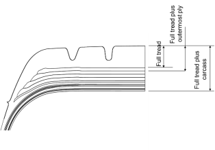
Full tread: The thickness of the tread rubber measured from the outer tread surface to the top of the outermost fabric or steel layer, including the rubber thickness above and below the tread groove bottom. Refer to the figure below (section of a tyre):
Hazardous fuel leak: a definition is provided in AMC 25.963(e).
Maximum unloaded operational pressure: Unloaded rated tyre pressure (available from the TRA Year Book) divided by the 1.07 factor from CS 25.733(c)(1).
Minimum tyre speed rating: The lowest tyre speed rating certified for the aeroplane in compliance with CS 25.733(a) or (c). The aeroplane manufacturer may decide to certify several tyre speed ratings; in this case, the lowest certified speed rating value should be taken as the ‘minimum tyre speed rating’ used in the models of this AMC.
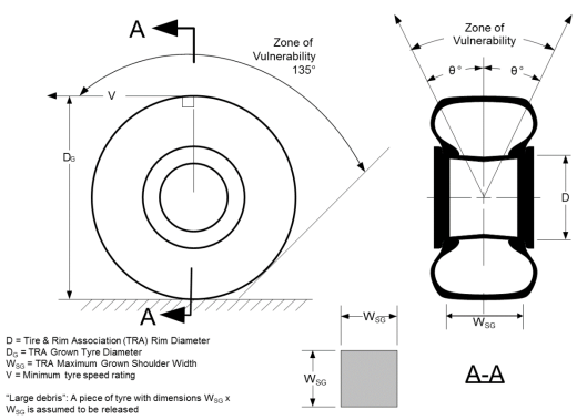
Total tread area: ∏.DG.WSG
Terms used in accordance with the Tire and Rim Association (TRA) Aircraft Year Book4 The Tire and Rim Association, Inc. (TRA) is the standardizing body for the tire, rim, valve and allied parts industry for the United States. TRA was founded in 1903 and its primary purpose is to establish and promulgate interchangeability standards for tires, rims, valves and allied parts. TRA standards are published in the Tire and Rim Year Book, Aircraft Year Book and supplemental publications. More information available at: http://www.us-tra.org/index.html.:
— D = TRA Rim Diameter
— DG = TRA Grown Tyre Diameter
— WSG = TRA Maximum Grown Shoulder Width
Tyre speed rating: The maximum ground speed at which the tyre has been tested in accordance with (E)TSO C62e.
4. Threat models
Model 1 — Tyre Debris Threat Model
Applicability: landing gear extended
(1) Threats occurring when the tyre is in contact with the ground release tyre debris.
Two tyre debris sizes are considered.
These debris are assumed to be released from the tread area of the tyre and projected towards the aircraft within the zones of vulnerability identified in Figure 1:
(i) a ‘large debris’ with dimensions WSG × WSG at DG and a thickness of the full tread plus outermost ply (i.e. the reinforcement or protector ply). The angle of vulnerability θ is 15°.
(ii) a ‘small debris’ consisting of 1 per cent of the total tyre mass, with an impact load distributed over an area equal to 1.5 per cent of the total tread area. The angle of vulnerability θ is 30°.
The debris have a speed equivalent to the minimum tyre speed rating certified for the aircraft (the additional velocity component due to the release of carcass pressure need not be taken into account).
Figure 1 – Tyre Debris Threats
(2) Protection of the fuel tank structure and pass-fail criteria on effects of penetration
(2.1) The large tyre debris size as defined in (i) above is assumed to penetrate and open the fuel tank or fuel system structure located in the zone of vulnerability defined in (i). It is used to define the opening size of the structural damage. A fuel leakage is assumed to occur whenever either the fuel tank structure or any structural element of fuel system components is struck by this large debris. It need not be used as a sizing case for structural design.
The fuel leakage should not result in hazardous quantities of fuel entering areas of the aeroplane that could present a hazard such as, but not limited to:
1. an engine air intake,
2. an APU air intake, or
3. a cabin air intake.
All practical measures should be taken to avoid fuel coming into contact with an ignition source (which may also result from the tyre failure event, e.g. electrical wire damage).
This should be shown by test or analysis, or a combination of both, for each engine forward thrust condition and each approved reverse thrust condition.
Alternatively, it is acceptable to demonstrate that the large tyre debris as defined in (i) above will not cause damage sufficient to allow a hazardous fuel leak whenever fuel tank deformation or rupture has been induced (including through propagation of pressure waves or cracking sufficient to allow a hazardous fuel leak).
(2.2) The small tyre debris as defined in (ii) should not create damage sufficient to allow a hazardous fuel leak in the zone of vulnerability defined in (ii).
(3) Protection of systems and pass-fail criteria
The two tyre debris sizes (defined in (i) and (ii) above) are considered. The sizes of debris are to be considered for the separation of systems.
When shielding is required (to protect a component or system), or when an energy analysis is required (for instance, for the validation of the structural parts of systems), the small debris defined in (ii) should be used.
An initial tyre failure can also result in failure of, and debris from, the companion tyre. This can occur even when the tyres have been designed to have double dynamic overload capability.
The analysis for the segregation of systems installation and routing should take this companion tyre failure into account inside the vulnerability zone defined by θ = 15° (either side of the tyre centre line) and only considering both tyres releasing large debris. Inside zones defined by 15° < θ ≤30°, where only the small debris size is applicable, only debris (defined in (ii)) from a single tyre needs to be considered.
A ‘companion’ tyre is a tyre on the same axle.
To demonstrate compliance with the applicable Certification Specifications, the following approach should be used:
(a) Identify all hazards associated with the possible impact areas defined by Figure 1, including simultaneous/cascade failure of companion tyres.
(b) All practicable design precautions should be taken to eliminate all Catastrophic failure situations by means of system separation and/or impact resistant shielding and/or redesign. Impact resistance should be assessed for small debris (type (ii)) impacts only. Consideration should also be given to Hazardous failure situations when showing compliance in accordance with CS 25.1309.
(c) Any Catastrophic failure situation that remains after accomplishment of step (b) above will be submitted to the Agency for consideration in accordance with step (d) below.
(d) If the Agency concludes that the applicant has taken all practicable precautions to prevent a Catastrophic failure situation and the probability of the occurrence is consistent with the hazard classification (assuming a probability of companion tyre failure, if applicable, equal to 10 per cent), the design would be considered as compliant with the intent of CS 25.734.
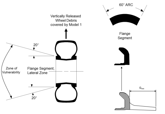
Model 2 — Wheel Flange Debris Threat Model
Applicability: gear extended
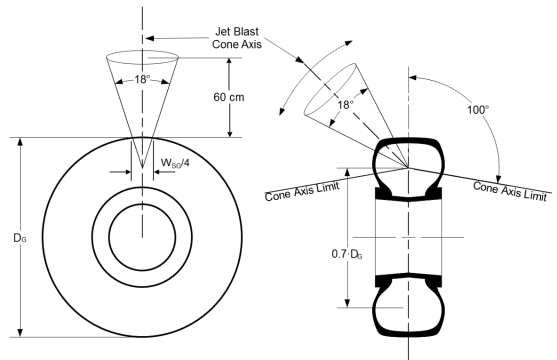
(1) It is considered that a 60° arc segment of the wheel flange can be released laterally, in the zones identified in Figure 2. The speed of release is 100 m/s (328 ft/s).
Where multiple wheels are installed on a landing gear leg, the lateral release of only the flange on the outer wheel halves needs to be considered.
If only a single wheel is installed on a landing gear leg, then the lateral release of either flange shall be considered.
(2) Vertically released debris are covered by Model 1 tyre debris.
(3) The debris should be considered to impact in the most critical condition.
Figure 2 – Wheel Flange Release Threat
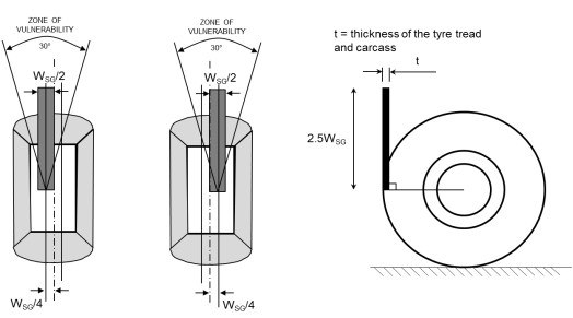
Model 3 — Flailing Tyre Strip Threat Model
(1) Model 3E: Landing Gear Extended
A flailing tyre strip with a length of 2.5 WSG and a width of WSG/2 will remain attached to the outside diameter of the rotating tyre at take-off speeds.
The thickness (t) of the loose strip of tyre is the full tread plus the carcass of the tyre. If the applicant demonstrates that the carcass will not fail, then the thickness may be reduced to full tread plus outermost ply (i.e. the reinforcement or protector ply).
The strip has a speed equivalent to the minimum tyre speed rating certified for the aircraft. For this threat the zone of vulnerability is 30°, as shown in Figure 3.
(2) Model 3R: Landing Gear Retracting or Retracted
The loose tyre strip and the conditions remain unchanged from that considered for the Gear Extended case. However, due to the wheel spin down after take-off, the rotational speed of the wheel may be lower or even zero as it enters the wheel bay.
If the aeroplane is equipped with a system braking the wheel during landing gear retraction (‘retraction brake’), then the applicant may take credit for this system provided:
(i) the retraction braking system is reliable and its failure is not latent;
(ii) the failure of the retraction brake is independent from a flailing tyre strip event;
(iii) the retraction braking stops the rotation of the tyre before the trajectory of the flailing tyre strip can cause a hazard to the aircraft; and
(iv) the effect of a zero velocity retraction with the loose strip of tyre is assessed.
The strip has an initial speed equivalent to the minimum tyre speed rating certified for the aircraft. Allowance for rotation speed reduction during retraction may be substantiated by the applicant. For this threat the zone of vulnerability is 30°, as shown in Figure 3.
Figure 3 – Flailing Tyre Strip Threat
Model 4 — Tyre Burst Pressure Effect Threat Model
Applicability: landing gear retracting or landing gear retracted
1) In-flight tyre bursts with the landing gear retracted are considered to result from previous damage to the tyre, which could occur at any point on the exposed surface. A review of the known incidents shows that all cases of retracted tyre burst have occurred to main gear with braked wheels. This hazard is therefore considered to be applicable only to tyres mounted on braked wheels.
2) It is assumed that tyres do not release debris and consequential damage is considered to be caused only from the pressure effects of resulting gas jet (‘blast effect’). The blast effect has been shown to differ between radial and bias tyres.
3) The tyre burst pressure is assumed to be 130 % of the maximum unloaded operational pressure, which is the unloaded tyre rated pressure reduced by a factor of 1.07 (safety factor required by CS 25.733(c)(1)).
Example: For an H44.5 × 16.5 – 21 26PR Tyre — The unloaded tyre rated pressure is 1 365 kPa (198 psig), so the maximum unloaded operational pressure is 1 365 / 1.07 = 1 276 kPa (185 psig), i.e. 1 377 kPa absolute pressure (199.7 psia); therefore the tyre burst pressure is 1 377 × 1.3 = 1 790 kPa absolute pressure (259.7 psia).
4) For bias tyres, the burst plume model shown in Figures 4a and 4b should be used, with the blast cone axis rotated over the tread surface of the tyre (± 100° as shown in
Figure 4a). The pressure distribution is provided in Figures 4b and 4c.
5) For radial tyres, the burst plume model (‘wedge’ shape) is shown in Figures 4d and 4e. The pressure decay formula provided in Figure 4e below should be used. It provides the level of pressure as a function of the distance from the tyre burst surface.
6) The effect of the burst should be evaluated on structure and system items located inside the defined burst plume. In addition, there should be no effect detrimental to continued safe flight and landing due to the increase in pressure of the wheel well as a result of a retracted tyre burst.
Figure 4a – Tyre Burst Pressure Effect – Bias Tyre
Note: ‘Grown dimensions’ should be calculated for bias tyres using TRA formulas.
Figure 4b – Tyre Burst Pressure Effect – Bias Tyre
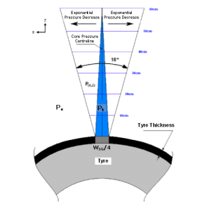
Figure 4c – Tyre Burst Pressure Effect – Bias Tyre
Air jet pressure distribution
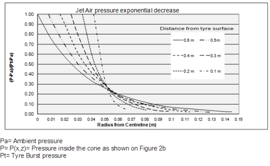
Figure 4d – Tyre Burst Pressure Effect – Radial Tyre
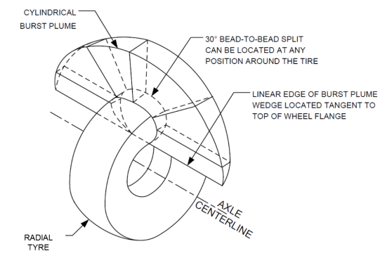
Figure 4e – Tyre Burst Pressure Effect – Radial Tyre
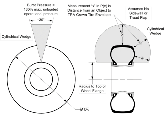
Radial Tyre Burst Pressure Decay Formula
![]()
Where:
Or:
and:
C1 = 12.478,
C2 = 1.222,
C3 = 0.024
WG = the Maximum Grown Section Width of the tyre [in or mm] as specified in the Tyre & Rim Association (TRA) designation for the tyre
Pt = Total or burst pressure [psia or bar]
P0 = Ambient pressure [psia or bar]
x = Distance from object to grown tyre surface [in or mm]
If P(x) > Pt then P(x) = Pt; otherwise P(x) = P(x).
[Amdt 25/14]
CS 25.735 Brakes and braking systems
ED Decision 2013/033/R
(See AMC 25.735)
(a) Approval. Each assembly consisting of a wheel(s) and brake(s) must be approved.
(b) Brake system capability. The brake system, associated systems and components must be designed and constructed so that:
(1) If any electrical, pneumatic, hydraulic, or mechanical connecting or transmitting element fails, or if any single source of hydraulic or other brake operating energy supply is lost, it is possible to bring the aeroplane to rest with a braked roll stopping distance of not more than two times that obtained in determining the landing distance as prescribed in CS 25.125.
(2) Fluid lost from a brake hydraulic system following a failure in, or in the vicinity of, the brakes is insufficient to cause or support a hazardous fire on the ground or in flight.
(c) Brake controls. The brake controls must be designed and constructed so that:
(1) Excessive control force is not required for their operation.
(2) If an automatic braking system is installed, means are provided to:
(i) Arm and disarm the system, and
(ii) Allow the pilot(s) to override the system by use of manual braking.
(d) Parking brake. The aeroplane must have a parking brake control that, when selected on, will, without further attention, prevent the aeroplane from rolling on a dry and level paved runway when the most adverse combination of maximum thrust on one engine and up to maximum ground idle thrust on any, or all, other engine(s) is applied. The control must be suitably located or be adequately protected to prevent inadvertent operation. There must be indication in the cockpit when the parking brake is not fully released.
(e) Anti-skid system. If an anti-skid system is installed:
(1) It must operate satisfactorily over the range of expected runway conditions, without external adjustment.
(2) It must, at all times, have priority over the automatic braking system, if installed.
(f) Kinetic energy capacity –
(1) Design landing stop. The design-landing stop is an operational landing stop at maximum landing weight. The design landing stop brake kinetic energy absorption requirement of each wheel, brake, and tyre assembly must be determined. It must be substantiated by dynamometer testing that the wheel, brake and tyre assembly is capable of absorbing not less than this level of kinetic energy throughout the defined wear range of the brake. The energy absorption rate derived from the aeroplane manufacturer’s braking requirements must be achieved. The mean deceleration must not be less than 3.1 m/s2 (10 fps2).
(2) Maximum kinetic energy accelerate-stop. The maximum kinetic energy accelerate-stop is a rejected take-off for the most critical combination of aeroplane take-off weight and speed. The accelerate-stop brake kinetic energy absorption requirement of each wheel, brake, and tyre assembly must be determined. It must be substantiated by dynamometer testing that the wheel brake and tyre assembly is capable of absorbing not less than this level of kinetic energy throughout the defined wear range of the brake. The energy absorption rate derived from the aeroplane's braking requirements must be achieved. The mean deceleration must not be less than 1.8 m/s2 (6 fps2).
(3) Most severe landing stop. The most severe landing stop is a stop at the most critical combination of aeroplane landing weight and speed. The most severe landing stop brake kinetic energy absorption requirement of each wheel, brake, and tyre assembly must be determined. It must be substantiated by dynamometer testing that, at the declared fully worn limit(s) of the brake heat sink, the wheel, brake and tyre assembly is capable of absorbing not less than this level of kinetic energy. The most severe landing stop need not be considered for extremely improbable failure conditions or if the maximum kinetic energy accelerate-stop energy is more severe.
(g) Brake condition after high kinetic energy dynamometer stop(s). Following the high kinetic energy stop demonstration(s) required by sub-paragraph (f) of this paragraph, with the parking brake promptly and fully applied for at least 3 minutes, it must be demonstrated that for at least 5 minutes from application of the parking brake, no condition occurs (or has occurred during the stop), including fire associated with the tyre or wheel and brake assembly, that could prejudice the safe and complete evacuation of the aeroplane.
(h) Stored energy systems. An indication to the flight crew of the usable stored energy must be provided if a stored energy system is used to show compliance with sub-paragraph (b)(1) of this paragraph. The available stored energy must be sufficient for:
(1) At least 6 full applications of the brakes when an anti-skid system is not operating; and
(2) Bringing the aeroplane to a complete stop when an anti-skid system is operating, under all runway surface conditions for which the aeroplane is certificated.
(i) Brake wear indicators. Means must be provided for each brake assembly to indicate when the heat sink is worn to the permissible limit. The means must be reliable and readily visible.
(j) Over-temperature burst prevention. Means must be provided in each braked wheel to prevent a wheel failure, a tyre burst, or both, that may result from elevated brake temperatures. Additionally, all wheels must meet the requirements of CS 25.731(d).
(k) Compatibility. Compatibility of the wheel and brake assemblies with the aeroplane and its systems must be substantiated.
(l) Wheel brake temperature. Equipment and structure that are essential to the safe operation of the aeroplane and that are located on the landing gear and in wheel wells must be protected from the damaging effects of possible wheel brake temperatures.
[Amdt 25/2]
[Amdt 25/14]
AMC 25.735 Brakes and Braking Systems Certification Tests and Analysis
ED Decision 2016/010/R
1. PURPOSE
This AMC (Acceptable Means of Compliance) which is similar to the FAA Advisory Circular AC 25.735-1 provides guidance material for use as an acceptable means, although not the only means, of demonstrating compliance with the requirements of CS 25.731 and CS 25.735. It also identifies other paragraphs of the EASA Certification Specifications (CS) that contain related requirements and other related and complementary documents.
2. RELATED REGULATORY MATERIAL AND COMPLEMENTARY DOCUMENTS
a. Related EASA Certification Specifications
PART-21 and CS-25 paragraphs (and their associated AMC material where applicable) that prescribe requirements related to the design substantiation and certification of brakes and braking systems include:
|
21A.303 |
Compliance with applicable Requirements |
|
General |
|
|
Accelerate-stop distance |
|
|
Landing |
|
|
Loads |
|
|
Factor of safety |
|
|
Extending retracting mechanisms |
|
|
Tyres |
|
|
Function and installation |
|
|
Equipment, systems and installations |
|
|
Warning, caution and advisory lights |
|
|
General: Systems and Equipment Limitations |
|
|
Markings and Placards: General |
|
|
Supplementary performance information |
Additional Part-21 and CS-25 paragraphs (and their associated AMC material where applicable) that prescribe requirements which can have a significant impact on the overall design and configuration of brakes and braking systems are, but are not limited to:
|
21A.101 |
Designation of applicable certification specifications and environmental protection requirements |
|
General: Control Systems |
|
|
Flammable fluid fire protection |
|
|
Fuel jettisoning system |
|
|
Flammable fluid-carrying components |
|
|
Flammable fluids |
|
|
Negative acceleration (FAR 25.943) |
b. Complementary Documents
Documents that provide appropriate standards for the design substantiation and certification of Brakes and Braking Systems are, but are not limited to:
(i) European Technical Standard Orders (ETSO)
|
ETSO-C47 |
Pressure Instruments - Fuel, Oil and Hydraulic |
|
ETSO-C26c |
Aircraft Wheels and Wheel-Brake Assemblies with Addendum I |
|
ETSO-2C75 |
Hydraulic Hose Assemblies |
|
ETSO-C62d |
Aircraft Tyres |
|
ETSO-C135 |
Transport Aeroplane Wheels and Wheel and Brake Assemblies |
(ii) Advisory Circulars/Acceptable Means of Compliance
|
AC 25.1309-1A |
System Design and Analysis |
|
AC 25-7C |
Flight Test Guide for Certification of Transport Category Airplanes |
|
AC 21-29A |
Detecting and Reporting Suspected Unapproved Parts |
|
AC 91-6A |
Water, Slush, and Snow on the Runway AMC 25.1591 The derivation and methodology of performance information for use when taking-off and landing with contaminated runway surface conditions. |
|
AMC 20-115 |
Software Considerations for Airborne Systems and Equipment Certification |
(iii) Society of Automotive Engineers (SAE) Documents
|
ARP 597C |
Wheels and Brakes, Supplementary Criteria for Design Endurance - Civil Transport Aircraft |
|
ARP 813A |
Maintainability Recommendations for Aircraft Wheels and Brakes |
|
AIR 1064B |
Brake Dynamics |
|
ARP 1070B |
Design and Testing of Anti-skid Brake Control Systems for Total Aircraft Compatibility |
|
AS 1145A |
Aircraft Brake Temperature Monitor System (BTMS) |
|
ARP 1619 |
Replacement and Modified Brakes and Wheels |
|
AIR 1739 |
Information on Anti-skid Systems |
|
ARP 1907 |
Automatic Braking Systems Requirements |
|
AIR 1934 |
Use of Carbon Heat Sink Brakes on Aircraft |
|
ARP 4102/2 |
Automatic Braking System (ABS) |
|
ARP 4752 |
Aerospace - Design and Installation of Commercial Transport Aircraft Hydraulic Systems (Note: This document provides a wide range of Civil, Military and Industry document references and standards which may be appropriate.) |
(iv) International Organisation for Standardisation (ISO) Documents
|
ISO 7137 |
Environmental Conditions and Test Procedures for Airborne Equipment. |
(v) US Military Documents
|
MIL-STD-810 |
Environmental Test Methods and Engineering Guidelines. |
(vi) The European Organisation for Civil Aviation Equipment Documents
|
ED-14G/RTCA DO-160G |
Environmental Conditions and Test Procedures for Airborne Equipment. |
|
AMC 20-115 |
Software Considerations for Airborne Systems and Equipment Certification. |
3. RESERVED
4. DISCUSSION
a. Ref. CS 25.735(a) Approval
(1) CS 25.735(a) states that each assembly consisting of a wheel(s) and brake(s) must be approved. Each wheel and brake assembly fitted with each designated and approved tyre type and size, where appropriate, should be shown to be capable of meeting the minimum standards and capabilities detailed in the applicable European Technical Standard Order (E)TSO, in conjunction with the type certification procedure for the aeroplane, or by any other means approved by the Agency. This applies equally to replacement, modified, and refurbished wheel and brake assemblies or components, whether the changes are made by the Original Equipment Manufacturer (OEM) or others. Additionally, the components of the wheels, brakes, and braking systems should be designed to:
(a) Withstand all pressures and loads, applied separately and in conjunction, to which they may be subjected in all operating conditions for which the aeroplane is certificated.
(b) Withstand simultaneous applications of normal and emergency braking functions, unless adequate design measures have been taken to prevent such a contingency.
(c) Meet the energy absorption requirements without auxiliary cooling devices (such as cooling fans).
(d) Not induce unacceptable vibrations at any likely ground speed and condition or any operating condition (such as retraction or extension).
(e) Protect against the ingress or effects of foreign bodies or materials (water, mud, oil, and other products) that may adversely affect their satisfactory performance. Following initial aeroplane certification, any additional wheel and brake assemblies should meet the applicable airworthiness requirements specified in 21 A.101(a) and (b) to eliminate situations that may have adverse consequences on aeroplane braking control and performance. This includes the possibility of the use of modified brakes either alone (i.e., as a ship set) or alongside the OEM’s brakes and the mixing of separately approved assemblies.
(2) Respecting brake energy qualification limits
The ETSO standard for wheels and wheel and brake assemblies includes an ‘Accelerate-Stop Test’ and a ‘Most Severe Landing Stop Test’ (if applicable), which establish the kinetic energy (KE) absorption capability of the brake assembly. The ETSO tests demonstrate the KE absorption capability of the brake with that brake at a predetermined (threshold) start temperature. Both of these tests are required to be performed on (new and worn) brakes with threshold temperatures that must ‘as closely as practicable, be representative of a typical in-service condition’.
Two methods are permitted and accepted by the Agency to calculate the energy required to bring the heat pack to this representative thermal condition:
(a) by a rational analysis; or
(b) by the addition of a percentage of the KERT Wheel/Brake Rated Accelerate-Stop Energy: 10 % for ‘Accelerate-Stop Test’ or 5 % for ‘Most Severe Landing Stop Test’.
A brake with an initial temperature higher than the threshold temperature has less KE absorption capability than it has at the threshold temperature. This could lead to the brake being unable to generate the required torque to stop the aeroplane in the available distance, or being unable to safely dissipate the additional thermal energy generated during the stop (hence, a risk of fire). Therefore, the applicant should ensure that the demonstrated brake KE absorption capability is not exceeded when the brake is installed on the aeroplane.
It should be demonstrated how the temperature thresholds, determined for the brake qualification testing, will not be exceeded.
Acceptable methods of demonstrating this include, but are not limited to, the following:
(a) use of brake temperature monitoring: by allowing the crew to check the brake temperature prior to a take-off, it can be ensured that that the brake temperature does not exceed thetemperature threshold of the demonstrated brake qualification testing, or
(b) use of brake cool-down charts: by establishing the cool-down rate of the brake heat sink, an estimate can be made that relates the energy absorbed by the brake to its temperature and also to the appropriate cool-down time.
Appropriate limitations have to be specified in the Aeroplane Flight Manual (AFM)
(3) Refurbished and Overhauled Equipment. Refurbished and overhauled equipment is equipment overhauled and maintained by the applicable OEM or its designee in accordance with the OEM’s Component Maintenance Manual (CMM) and associated documents. It is necessary to demonstrate compliance of all refurbished configurations with the applicable (E)TSO and aeroplane manufacturer’s specifications. It is also necessary to verify that performances are compatible for any combination of mixed brake configurations, including refurbished/overhauled and new brakes. It is essential to assure that Aeroplane Flight Manual braking performance and landing gear and aeroplane structural integrity are not adversely altered.
(4) Replacement and Modified Equipment. Replacement and modified equipment includes changes to any approved wheel and brake assemblies not addressed under paragraph 4a(2) of this AMC. Consultation with the aeroplane manufacturer on the extent of testing is recommended. Particular attention should be paid to potential differences in the primary brake system parameters (e.g., brake torque, energy capacity, vibration, brake sensitivity, dynamic response, structural strength, and wear state). If comparisons are made to previously approved equipment, the test articles (other than the proposed parts to be changed) and conditions should be comparable, as well as the test procedures and equipment on which comparative tests are to be conducted. For wheel and brake assembly tests, the tyre size, manufacturer, and ply rating used for the test should be the same and the tyre condition should be comparable. For changes of any heat sink component parts, structural parts (including the wheel), and friction elements, it is necessary to provide evidence of acceptable performance and compatibility with the aeroplane and its systems.
(a) Minor Changes. Changes to a brake might be considered as a minor change, as long as the changes are not to the friction elements. The proposed change cannot affect the aeroplane stopping performance, brake energy absorption characteristics, and/or continued airworthiness of the aeroplane or wheel and brake assembly (e.g., vibration and/or thermal control, and brake retraction integrity). Technical evidence justifying a minor change should be provided.
(b) Major Changes. Changes to a wheel assembly outside the limits allowed by the OEM’s CMM should be considered a major change due to potential airworthiness issues.
(c) Past history with friction elements has indicated the necessity of ongoing monitoring (by dynamometer test) of frictional and energy absorption capabilities to assure that they are maintained over the life of the aeroplane program. These monitoring plans have complemented the detection and correction of unacceptable deviations. A monitoring plan should be submitted to the cognisant Certification Office to ensure continued airworthiness of the product.
(d) Intermixing of wheel and brake assemblies from different suppliers is generally not acceptable due to complexities experienced with different friction elements, specific brake control tuning, and other factors.
b. Ref. CS 25.735(b) Brake System Capability
(1) The system should be designed so that no single failure of the system degrades the aeroplane stopping performance beyond doubling the braked roll stopping distance (refer to CS 25.735(b)(1)). Failures are considered to be fracture, leakage, or jamming of a component in the system, or loss of an energy source. Components of the system include all parts that contribute to transmitting the pilot's braking command to the actual generation of braking force. Multiple failures resulting from a single cause should be considered a single failure (e.g., fracture of two or more hydraulic lines as a result of a single tyre failure). Sub-components within the brake assembly, such as brake discs and actuators (or their equivalents), should be considered as connecting or transmitting elements, unless it is shown that leakage of hydraulic fluid resulting from failure of the sealing elements in these sub-components within the brake assembly would not reduce the braking effectiveness below that specified in CS 25.735(b)(1).
(a) In order to meet the stopping distance requirements of CS 25.735(b)(1) in the event of failure of the normal brake system, it is common practice to provide an alternate brake system. The normal and alternate braking systems should be independent, being supplied by separate power sources. Following a failure of the normal system, the changeover to a second system (whether manually or by automatic means) and the functioning of a secondary power source should be effected rapidly and safely. The changeover should not involve risk of wheel locking, whether the brakes are applied or not at the time of changeover.
(b) The brake systems and components should be separated or appropriately shielded so that complete failure of the braking system(s) as a result of a single cause is minimised.
(2) Compliance with CS 25.735(b)(2) may be achieved by:
(a) Showing that fluid released would not impinge on the brake, or any part of the assembly that might cause the fluid to ignite;
(b) Showing that the fluid will not ignite; or
(c) Showing that the maximum amount of fluid released is not sufficient to sustain a fire.
(3) Additionally, in the case of a fire, it may be shown that the fire is not hazardous, taking into consideration such factors as landing gear geometry, location of fire sensitive (susceptibility) equipment and installations, system status, flight mode, etc.
If more than one fluid is allowed for the hydraulic system, compliance should be addressed for all fluids.
c. Ref. CS 25.735(c) Brake Controls
(1) The braking force should increase or decrease progressively as the force or movement applied to the brake control is increased or decreased (refer to CS 25.735(c)(1)). The braking force should respond to the control as quickly as is necessary for safe and satisfactory operation. A brake control intended only for parking need not operate progressively. There should be no requirement to select the parking brake “off” in order to achieve a higher braking force with manual braking.
(2) When an automatic braking system is installed (refer to CS 25.735(c)(2)) such that various levels of braking (e.g., low, medium, high) may be preselected to occur automatically following a touchdown, the pilot(s) should be provided with a means that is separate from other brake controls to arm and/or disarm the system prior to the touchdown.
(3) The automatic braking system design should be evaluated for integrity and non-hazard, including the probability and consequence of insidious failure of critical components, and non interference with the non-automatic braking system. Single failures in the automatic braking system should not compromise non-automatic braking of the aeroplane. Automatic braking systems that are to be approved for use in the event of a rejected take-off should have a single selector position, set prior to take-off, enabling this operating mode.
d. Ref. CS 25.735(d) Parking Brake
It should be demonstrated that the parking brake has sufficient capability in all allowable operating conditions (Master Minimum Equipment List (MMEL) to be able to prevent the rotation of braked wheels. This demonstration is to be accomplished with the stated engine power settings, and with the aeroplane configuration (i.e., ground weight, c.g., position and nose-wheel (or tail-wheel) angle) least likely to result in skidding on a dry, level runway surface (refer to CS 25.735(d)). Use of ground idle thrust on the “other” engine is not mandatory, higher thrust levels may be used to prevent aeroplane motion due to the asymmetric engine thrust. Where reliable test data are available, substantiation by means other than aeroplane testing may be acceptable.
(1) For compliance with the requirement for indication that the parking brake is not fully released, the indication means should be associated, as closely as is practical, with actual application of the brake rather than the selector (control). The intent is to minimise the possibility of false indication due to failures between the brake and the point at which the parking brake state is sensed. This requirement is separate from, and in addition, to the parking brake requirements associated with CS 25.703(a)(3), Take-off warning systems.
(2) The parking brake control, whether or not it is independent of the emergency brake control, should be marked with the words "Parking Brake" and should be constructed in such a way that, once operated, it can remain in the selected position without further flight crew attention. It should be located where inadvertent operation is unlikely, or be protected by suitable means against inadvertent operation.
e. Ref. CS 25.735(e) Anti-skid System
(1) If an anti-skid system is installed (refer to CS 25.735(e)), then no single failure in the antiskid system should result in the brakes being applied, unless braking is being commanded by the pilot. In the event of an anti-skid system failure, means should be available to allow continued braking without anti-skid. These means may be automatic, pilot controlled, or both.
(2) Compliance with CS 25.735(e)(1) and (e)(2) may be achieved by:
(a) Failures that render the system ineffective should not prevent manual braking control by the pilot(s) and should normally be indicated. Failure of wheels, brakes, or tyres should not inhibit the function of the anti-skid system for unaffected wheel, brake, and tyre assemblies.
(b) The anti-skid system should be capable of giving a satisfactory braking performance over the full range of tyre to runway friction coefficients and surface conditions, without the need for preflight or pre-landing adjustments or selections. The range of friction coefficients should encompass those appropriate to dry, wet, and contaminated surfaces and for both grooved and ungrooved runways.
(c) The use of the phrase “without external adjustment” is intended to imply that once the antiskid system has been optimised for operation over the full range of expected conditions for which the aeroplane is to be type certificated, pre-flight or pre-landing adjustments made to the equipment to enable the expected capabilities to be achieved are not acceptable. For example, a specific prelanding selection for a landing on a contaminated low µ (friction level) runway, following a take-off from a dry high µ runway, should not be necessary for satisfactory braking performance to be achieved.
(d) It should be shown that the brake cycling frequency imposed by the anti-skid installation will not result in excessive loads on the landing gear. Anti-skid installations should not cause surge pressures in the brake hydraulic system that would be detrimental to either the normal or emergency brake system and components.
(e) The system should be compatible with all tyre sizes and type combinations permitted and for all allowable wear states of the brakes and tyres. Where brakes of different types or manufacture are permitted, compatibility should be demonstrated or appropriate means should be employed to ensure that undesirable combinations are precluded.
(f) The anti-skid function must be able to reduce braking for a wheel/tyre that is going into a skid, whether the braking level is commanded by the pilot or an auto-brake system if installed.
f. Ref. CS 25.735(f) Kinetic Energy Capacity
The kinetic energy capacity of each tyre, wheel, and brake assembly should be at least equal to that part of the total aeroplane energy that the assembly will absorb during a stop, with the heat sink at a defined condition at the commencement of the stop (Refer to CS 25.735(f)).
(1) Calculation of Stop Kinetic Energy.
(a) The design landing stop, the maximum kinetic energy accelerate-stop, and the most severe landing stop brake kinetic energy absorption requirements of each wheel and brake assembly should be determined using either of the following methods:
(i) A conservative rational analysis of the sequence of events expected during the braking manoeuvre; or
(ii) A direct calculation based on the aeroplane kinetic energy at the commencement of the braking manoeuvre.
(b) When determining the tyre, wheel, and brake assembly kinetic energy absorption requirement using the rational analysis method, the analysis should use conservative values of the aeroplane speed at which the brakes are first applied, the range of the expected coefficient of friction between the tyres and runway, aerodynamic and propeller drag, powerplant forward thrust, and, if more critical, the most adverse single engine or propeller malfunction.
(c) When determining the tyre, wheel, and brake assembly energy absorption requirement using the direct calculation method, the following formula, which needs to be modified in cases of designed unequal braking distribution, should be used:
KE = 0.0443 WV2/N (ft-lb.)
where KE = Kinetic Energy per wheel (ft-lb.)
N = Number of main wheels with brakes
W = Aeroplane Weight (lb.)
V = Aeroplane Speed (knots)
or if SI (Metric) units are used:
KE = 1/2 mV2/N (Joule)
where KE = Kinetic Energy per wheel (J)
N = Number of main wheels with brakes
m = Aeroplane Mass (kg.)
V = Aeroplane Speed (m/s)
(d) For all cases, V is the ground speed and takes into account the prevailing operational conditions. All approved landing flap conditions should be considered when determining the design landing stop energy.
(e) These calculations should account for cases of designed unequal braking distributions. “Designed unequal braking distribution” refers to unequal braking loads between wheels that result directly from the design of the aeroplane. An example would be the use of both main-wheel and nosewheel brakes, or the use of brakes on a centreline landing gear supporting lower vertical loads per braked wheel than the main landing gear braked wheels. It is intended that this term should account for effects such as runway crown. Crosswind effects need not be considered.
(f) For the design landing case, the aeroplane speed should not be less than VREF/1.3, where VREF is the aeroplane steady landing approach speed at the maximum design landing weight and in the landing configuration at sea level. Alternatively, the aeroplane speed should not be less than VSO, the power-off stall speed of the aeroplane at sea level, at the design landing weight, and in the landing configuration.
(g) For the most severe landing case, the effects and consequences of typical single and multiple failure conditions that are foreseeable events and can necessitate landings at abnormal speeds and weights should be addressed. The critical landing weight for this condition is the maximum take-off weight, less fuel burned and jettisoned during a return to the departure airfield. A 30-minute flight should be assumed, with 15 minutes of active fuel jettisoning if equipped with a fuel jettisoning system.
(2) Heat Sink Condition at Commencement of the Stop.
(a) For the maximum kinetic energy accelerate-stop case, the calculation should account for:
(i) The brake temperature following a previous typical landing,
(ii) The effects of braking during taxi-in, the temperature change while parked,
(iii) The effects of braking during taxi-out, and
(iv) The additional temperature change during the take-off acceleration phase, up to the time of brake application.
(b) The analysis may not take account of auxiliary cooling devices. Assessment of ambient conditions within the operational limits established by the applicant and the typical time the aeroplane will be on the ground should be used.
(c) For the most severe landing stop case, the same temperature conditions and changes used for the maximum kinetic energy accelerate-stop case should be assumed, except that further temperature change during the additional flight phase may be considered.
(d) The brake temperature at the commencement of the braking manoeuvre should be determined using the rational analysis method. However, in the absence of such analysis, an arbitrary heat sink temperature should be used equal to the normal ambient temperature, increased by the amount that would result from a 10 percent maximum kinetic energy accelerate-stop for the acceleratestop case and from a 5 percent maximum kinetic energy accelerate-stop for landing cases. The temperature determined for the beginning of the test becomes the highest allowable temperature at commencement of the take-off run unless another test is performed at a higher temperature.
(3) Substantiation.
(a) Substantiation is required to show that the wheel and brake assembly is capable of absorbing the determined levels of kinetic energy at all permitted wear states up to and including the declared fully worn limits. The term “wear state" is used to clarify that consideration should be given to possible inconsistencies or irregularities in brake wear in some circumstances, such as greater wear at one end of the heat sink than the other end. Qualification related to equally distributed heat sink wear may not be considered adequate. If in-service wear distribution is significantly different from wear distribution used during qualification testing, additional substantiation and/or corrective action may be necessary.
(b) The minimum initial brakes-on speed used in the dynamometer tests should not be more than the velocity (V) used in the determination of the kinetic energy requirements of CS 25.735(f). This assumes that the test procedure involved a specific rate of deceleration and, therefore, for the same amount of kinetic energy, a higher initial brakes-on speed would result in a lower rate of energy absorption. Such a situation is recognised and is similarly stated in (E)TSO-C135, which provides an acceptable means for brake approval under CS 25.735(a).
(c) For certification purposes, a brake having a higher initial brakes-on speed is acceptable if the dynamometer test showed that both the energy absorbed and the energy absorption rates required by CS 25.735(f) had been achieved.
(d) Brake qualification tests are not intended as a means of determining expected aeroplane stopping performance, but may be used as an indicator for the most critical brake wear state for aeroplane braking performance measurements.
g. Ref. CS 25.735(g) Brake Condition after High Kinetic Energy Dynamometer Stop(s)
(1) Following the high kinetic energy stop(s), the parking brake should be capable of restraining further movement of the aeroplane and should maintain this capability for the period during which the need for an evacuation of the aeroplane can be determined and then fully accomplished. It should be demonstrated that, with a parking brake application within a period not exceeding 20 seconds of achieving a full stop, or within 20 seconds from the time that the speed is retarded to 37 km/h (20 knots) (or lower), in the event that the brakes are released prior to achieving a full stop (as permitted by (E)TSO-C135), the parking brake can be applied normally and that it remains functional for at least 3 minutes.
(2) Practical difficulties associated with dynamometer design may preclude directly demonstrating the effectiveness of the parking brake in the period immediately following the high energy dynamometer stop(s). Where such difficulties prevail, it should be shown that, for the 3-minute period, no structural failure or other condition of the brake components occurs that would significantly impair the parking brake function.
(3) Regarding the initiation of a fire, it should be demonstrated that no continuous or sustained fire, extending above the level of the highest point of the tyre, occurs before the 5-minute period has elapsed. Neither should any other condition arise during this same period or during the stop, either separately or in conjunction with a fire, that could be reasonably judged to prejudice the safe and complete aeroplane evacuation. Fire of a limited extent and of a temporary nature (e.g., those involving wheel bearing lubricant or minor oil spillage) is acceptable. For this demonstration, neither fire-fighting means nor coolants may be applied.
h. Ref. CS 25.735(h) Stored energy systems
(1) Stored energy systems use a self-contained source of power, such as a pressurised hydraulic accumulator or a charged battery (refer to CS 25.735(h)). This requirement is not applicable for those aeroplanes that provide a number of independent braking systems, including a stored energy system, but are not "reliant" on the stored energy system for the demonstration of compliance with CS 25.735(b).
(2) The indication of usable stored energy should show:
(a) The minimum energy level necessary to meet the requirements of CS 25.735(b)(1) and (h) (i.e., the acceptable level for dispatch of the aeroplane);
(b) The remaining energy level; and
(c) The energy level below which further brake application may not be possible.
(3) If a gas pressurised hydraulic accumulator is to be used as the energy storage means, indication of accumulator pressure alone is not considered adequate means to indicate available stored energy, unless verification can be made of the correct pre-charge pressure with the hydraulic system pressure off and the correct fluid volume with the hydraulic system pressure on. Furthermore, additional safeguards may be necessary to ensure that sufficient energy will be available at the end of the flight. Similar considerations should be made if other stored energy systems are used.
(4) A full brake application cycle is defined as an application from brakes fully released to brakes fully applied, and back to fully released.
i. Ref. CS 25.735(i) Brake wear indicators
The indication means should be located such that no special tool or illumination (except in darkness) is required. Expert interpretation of the indication should not be necessary (refer to CS 25.735(i)).
j. Ref. CS 25.731(d) and CS 25.735(j) Over-temperature and Over-pressure Burst Prevention
Over-temperature and over-pressure burst prevention. Generally, two separate types of protection should be provided: one specifically to release the tyre pressure should the wheel temperature increase to an unacceptable level, and the other to release the tyre pressure should the pressure become unacceptably high, particularly during the inflation process. The temperature sensitive devices are required in braked wheels only, but the pressure sensitive devices are required in all wheels (refer to CS 25.735(j) and 25.731(d)).
(1) The temperature sensitive devices (e.g., fuse or fusible plugs) should be sufficient in number and appropriately located to reduce the tyre pressure to a safe level before any part of the wheel becomes unacceptably hot, irrespective of the wheel orientation. The devices should be designed and installed so that once operated (or triggered) their continued operation is not impaired by the releasing gas. The effectiveness of these devices in preventing hazardous tyre blow-out or wheel failure should be demonstrated. It should also be demonstrated that the devices will not release the tyre pressure prematurely during take-off and landing, including during “quick turnaround” types of operation.
(2) It should be shown that the over-pressurisation devices, or the devices in conjunction with the tyre inflation means permanently installed in the wheel, would not permit the tyre pressure to reach an unsafe level regardless of the capacity of the inflation source.
(3) Both types of devices should normally be located within the structure of the wheel in positions that minimise the risk of damage or tampering during normal maintenance.
k. Ref. CS 25.735(k) Compatibility
Compliance with CS 25.735(k) may be achieved by the following:
(1) As part of the overall substantiation of safe and anomaly free operation, it is necessary to show that no unsafe conditions arise from incompatibilities between the brakes and brake system with other aeroplane systems and structures. Areas that should be explored include anti-skid tuning, landing gear dynamics, tyre type and size, brake combinations, brake characteristics, brake and landing gear vibrations, etc. Similarly, wheel and tyre compatibility should be addressed. These issues should be readdressed when the equipment is modified.
(2) During brake qualification testing, sufficient dynamometer testing over the ranges of permissible brake wear states, energy levels, brake pressures, brake temperatures, and speeds should be undertaken to provide information necessary for systems integration.
l. Ref. CS 25.735(l) Wheel brake temperature.
The use of fusible plugs in the wheels is not a complete safeguard against damage due to tyre burst. Where brake overheating could be damaging to the structure of, or equipment in, the wheel wells, an indication of brake temperature should be provided to warn the pilot.
[Amdt No: 25/2]
[Amdt No: 25/8]
[Amdt No: 25/12]
[Amdt No: 25/14]
[Amdt No: 25/18]
ED Decision 2003/2/RM
For determination of the design landing brake kinetic energy capacity rating, the initial condition of the brakes may be selected and can be any condition representative of service use, including new, and which satisfies the applicable ETSO or other acceptable brake qualification test standard.
ED Decision 2016/010/R
(See AMC 25.745)
(a) The nose-wheel steering system, unless it is restricted in use to low-speed manoeuvring, must be so designed that exceptional skill is not required for its use during take-off and landing, including the case of cross-wind, and in the event of sudden power-unit failure at any stage during the take-off run. This must be shown by tests. (See AMC 25.745(a).)
(b) It must be shown that, in any practical circumstances, movement of the pilot’s steering control (including movement during retraction or extension or after retraction of the landing gear) cannot interfere with the correct retraction or extension of the landing gear.
(c) Under failure conditions the system must comply with CS 25.1309(b) and (c). The arrangement of the system must be such that no single failure will result in a nose-wheel position, which will lead to a Hazardous Effect. Where reliance is placed on nose-wheel steering in showing compliance with CS 25.233, the nose-wheel steering system must be shown to comply with CS 25.1309. (See AMC 25.745(c).)
(d) The nose-wheel steering system, towing attachment(s), and associated elements must be designed or protected by appropriate means such that during ground manoeuvring operations effected by means independent of the aeroplane:
(1) Damage affecting the safe operation of the nose-wheel steering system is precluded, or
(2) A flight crew alert is provided, before the start of taxiing, if damage may have occurred (see AMC 25.1322).
(See AMC 25.745(d))
(e) Unless the nose-wheel, when lowered, is automatically in the fore-and-aft attitude successful landings must be demonstrated with the nose-wheel initially in all possible off-centre positions.
[Amdt 25/2]
[Amdt 25/13]
[Amdt 25/18]
AMC 25.745(a) Nose-wheel steering
ED Decision 2003/2/RM
In a powered nose-wheel steering system the normal supply for steering should continue without interruption in the event of failure of any one power-unit. With the remaining power-units operating at ground idling condition, the power supply should be adequate –
a. To complete an accelerate-stop manoeuvre following a power-unit failure which occurs during take-off, and
b. To complete a landing manoeuvre following a power-unit failure which occurs during take-off or at any later stage of flight.
AMC 25.745(c) Nose-wheel steering
ED Decision 2003/2/RM
1 No failure or disconnection need be assumed in respect of parts of proven integrity e.g. a simple jack or manual selector valve, but slow leakage from pipe joints and fracture of pipes should be considered as probable failures.
2 In assessing where the inadvertent application of steering torque as a result of a single failure would lead to danger, allowance may be made for the pilot’s instinctive reaction to the effects of the fault. However, dependent on the urgency and rapidity of warning of the failure given to the pilot, allowance should be made for a reaction time before it is assumed that the pilot takes any corrective action.
AMC 25.745(d) Nose-wheel steering
ED Decision 2013/010/R
CS 25.745(d) provides for the two following options:
1. A ‘no damage’ situation exists, because damage is precluded.
2. Damage can occur, but indication to the flight crew is provided.
(a) General consideration to CS 25.745(d)(1) and (2)
Some damage may occur during ground manoeuvring activities that can be considered acceptable and judged to be normal wear and tear. It is not intended that such damage needs necessarily to be precluded or that it should initiate a flight crew alert.
(b) To comply with CS 25.745(d)(1) the following applies:
The aeroplane may be designed in such a way that under all ground manoeuvring operations by any towing means, no damage affecting the steering system can occur.
Examples are:
— The steering system is designed sufficiently strong to resist any applied towing input.
— The steering system is designed to allow 360 degrees rotation.
— The steering system is disconnected either automatically or by operational procedure.
— The steering system is protected by shear sections installed on the nose landing gear.
(c) To comply with CS 25.745(d)(2), the following applies:
When protection is afforded by the flight crew alerting system, the damage detection means should be independent of the availability of aeroplane power supplies and should be active during ground manoeuvring operations effected by means independent of the aeroplane. If damage may have occurred, a latched signal should be provided to the flight crew alerting system.
(d) Alternative Acceptable Means of Compliance to CS 25.745(d)(1) and (2):
In the case where the aeroplane design does not comply with CS 25.745(d)(1) and (d)(2), the following apply:
(1) The Aeroplane Flight Manual, in the Section Limitations, should include a statement that ‘Towbarless towing is prohibited’, or
(2) The Aeroplane Flight Manual, in the Section Limitations, should include a statement that:
‘Towbarless towing is prohibited unless the towbarless towing operations are performed in compliance with the appropriate operational regulation using towbarless towing vehicles that are designed and operated to preclude damage to the aeroplane nose wheel steering system, or which provide a reliable and unmistakable warning when damage to the steering system has occurred.
Towbarless towing vehicles that are specifically accepted for this type of aeroplane are listed in the [appropriate maintenance documentation] provided by the aeroplane manufacturer.’
‘Appropriate maintenance documentation’ means Instructions for Continued Airworthiness as described in Appendix H, paragraph H25.3(a)(4) of CS-25.
(3) The acceptance by the aeroplane manufacturer of the applicable towbarless towing vehicles and its reliability of the oversteer protection and/or indication system as referred to in subparagraph ((d)(2)) above should be based on the following:
(i) The aeroplane Nose Wheel Steering Failure Analysis should include the effects of possible damage caused by towbarless towing operations.
(ii) If the Nose Wheel Steering Failure Analysis shows that damage to the steering system by the use of towbarless towing may result in a Failure Condition that can be classified as Hazardous or Catastrophic (refer to CS 25.1309), the acceptance of a towing vehicle oversteer protection and/or indication system should be based on an aeroplane safety analysis, encompassing the reliability of that vehicle system in order to meet the aeroplane safety objectives.
(iii) If the Nose Wheel Steering Failure Analysis shows that damage to the steering system by the use of towbarless towing may result in a Failure Condition that can be classified as Major or less severe, the aeroplane manufacturer can accept the design of the towing vehicle oversteer indication and/or protection system based on a ‘Declaration of Compliance’, issued by the towbarless towing vehicle manufacturer. This declaration will state that the vehicle design complies with the applicable standards (SAE ARPs, Aeroplane Towing Assessment Criteria Document) and that it is designed and built under ISO 9001 quality standards or equivalent.
Such a declaration must be made regarding all Towbarless Towing Vehicles to be used for ground manoeuvring of CS-25 certificated aeroplanes.
[Amdt 25/13]