
CS 25.251 Vibration and buffeting
ED Decision 2016/010/R
(See AMC 25.251)
(a) The aeroplane must be demonstrated in flight to be free from any vibration and buffeting that would prevent continued safe flight in any likely operating condition.
(b) Each part of the aeroplane must be demonstrated in flight to be free from excessive vibration under any appropriate speed and power conditions up to VDF/MDF. The maximum speeds shown must be used in establishing the operating limitations of the aeroplane in accordance with CS 25.1505.
(c) Except as provided in sub-paragraph (d) of this paragraph, there may be no buffeting condition, in normal flight, including configuration changes during cruise, severe enough to interfere with the control of the aeroplane, to cause excessive fatigue to the crew, or to cause structural damage. Stall warning buffeting within these limits is allowable.
(d) There may be no perceptible buffeting condition in the cruise configuration in straight flight at any speed up to VMO/MMO, except that the stall warning buffeting is allowable.
(e) For an aeroplane with MD greater than 0·6 or with a maximum operating altitude greater than 7620 m (25,000 ft), the positive manoeuvring load factors at which the onset of perceptible buffeting occurs must be determined with the aeroplane in the cruise configuration for the ranges of airspeed or Mach number, weight, and altitude for which the aeroplane is to be certificated. The envelopes of load factor, speed, altitude, and weight must provide a sufficient range of speeds and load factors for normal operations. Probable inadvertent excursions beyond the boundaries of the buffet onset envelopes may not result in unsafe conditions. (See AMC 25.251(e).)
[Amdt 25/1]
[Amdt 25/18]
AMC 25.251(e) Vibration and Buffeting in Cruising Flight
ED Decision 2003/2/RM
1 Probable Inadvertent Excursions beyond the Buffet Boundary
1.1 CS 25.251(e) states that probable inadvertent excursions beyond the buffet onset boundary may not result in unsafe conditions.
1.2 An acceptable means of compliance with this requirement is to demonstrate by means of flight tests beyond the buffet onset boundary that hazardous conditions will not be encountered within the permitted manoeuvring envelope (as defined by CS 25.337) without adequate prior warning being given by severe buffeting or high stick forces.
1.3 Buffet onset is the lowest level of buffet intensity consistently apparent to the flight crew during normal acceleration demonstrations in smooth air conditions.
1.4 In flight tests beyond the buffet onset boundary to satisfy paragraph 1.2, the load factor should be increased until either –
a. The level of buffet becomes sufficient to provide an obvious warning to the pilot which is a strong deterrent to further application of load factor; or
b. Further increase of load factor requires a stick force in excess of 445 N (100 lbf), or is impossible because of the limitations of the control system; or
c. The positive limit manoeuvring load factor established in compliance with CS 25.337(b) is achieved.
1.5 Within the range of load factors defined in paragraph 1.4 no hazardous conditions (such as hazardous involuntary changes of pitch or roll attitude, engine or systems malfunctioning which require urgent corrective action by the flight crew, or difficulty in reading the instruments or controlling the aeroplane) should be encountered.
2 Range of Load Factor for Normal Operations
2.1 CS 25.251(e) requires that the envelopes of load factor, speed, altitude and weight must provide a sufficient range of speeds and load factors for normal operations.
2.2 An acceptable means of compliance with the requirement is to establish the maximum altitude at which it is possible to achieve a positive normal acceleration increment of 0·3 g without exceeding the buffet onset boundary.
CS 25.253 High-speed characteristics
ED Decision 2016/010/R
(a) Speed increase and recovery characteristics. The following speed increase and recovery characteristics must be met:
(1) Operating conditions and characteristics likely to cause inadvertent speed increases (including upsets in pitch and roll) must be simulated with the aeroplane trimmed at any likely cruise speed up to VMO/MMO. These conditions and characteristics include gust upsets, inadvertent control movements, low stick force gradient in relation to control friction, passenger movement, levelling off from climb, and descent from Mach to air speed limit altitudes.
(2) Allowing for pilot reaction time after effective inherent or artificial speed warning occurs, it must be shown that the aeroplane can be recovered to a normal attitude and its speed reduced to VMO/MMO, without –
(i) Exceptional piloting strength or skill;
(ii) Exceeding VD/MD, VDF/MDF, or the structural limitations; and
(iii) Buffeting that would impair the pilot’s ability to read the instruments or control the aeroplane for recovery.
(3) With the aeroplane trimmed at any speed up to VMO/MMO, there must be no reversal of the response to control input about any axis at any speed up to VDF/MDF. Any tendency to pitch, roll, or yaw must be mild and readily controllable, using normal piloting techniques. When the aeroplane is trimmed at VMO/MMO, the slope of the elevator control force versus speed curve need not be stable at speeds greater than VFC/MFC, but there must be a push force at all speeds up to VDF/MDF and there must be no sudden or excessive reduction of elevator control force as VDF/MDF is reached.
(4) Adequate roll capability to assure a prompt recovery from a lateral upset condition must be available at any speed up to VDF/MDF. (See AMC 25.253(a)(4).)
(5) Extension of speedbrakes. With the aeroplane trimmed at VMO/MMO, extension of the speedbrakes over the available range of movements of the pilots control, at all speeds above VMO/MMO, but not so high that VDF/MDF would be exceeded during the manoeuvre, must not result in:
(i) An excessive positive load factor when the pilot does not take action to counteract the effects of extension;
(ii) Buffeting that would impair the pilot’s ability to read the instruments or control the aeroplane for recovery; or
(iii) A nose-down pitching moment, unless it is small. (See AMC 25.253(a)(5).)
(6) Reserved
(b) Maximum speed for stability characteristics, VFC/MFC. VFC/MFC is the maximum speed at which the requirements of CS 25.143(g), 25.147(f), 25.175(b)(1), 25.177(a) through (c), and 25.181 must be met with wing-flaps and landing gear retracted. Except as noted in CS 25.253(c), VFC/MFC may not be less than a speed midway between VMO/MMO and VDF/MDF, except that, for altitudes where Mach Number is the limiting factor, MFC need not exceed the Mach Number at which effective speed warning occurs.
(c) Maximum speed for stability characteristics in icing conditions. The maximum speed for stability characteristics with the most critical of the ice accretions defined in Appendices C and O, as applicable, in accordance with CS 25.21(g), at which the requirements of CS 25.143(g), 25.147(f), 25.175(b)(1), 25.177(a) through (c) and 25.181 must be met, is the lower of:
(1) 556 km/h (300 knots) CAS,
(2) VFC, or
(3) A speed at which it is demonstrated that the airframe will be free of ice accretion due to the effects of increased dynamic pressure."
[Amdt. 25/3]
[Amdt 25/11]
[Amdt 25/16]
[Amdt 25/18]
AMC 25.253(a)(4) Lateral Control: Roll Capability
ED Decision 2003/2/RM
An acceptable method of demonstrating compliance with CS 25.253(a)(4) is as follows:
1 Establish a steady 20° banked turn at a speed close to VDF/MDF limited to the extent necessary to accomplish the following manoeuvre and recovery without exceeding VDF/MDF. Using lateral control alone, it should be demonstrated that the aeroplane can be rolled to 20° bank angle in the other direction in not more than 8 seconds. The demonstration should be made in the most adverse direction. The manoeuvre may be unchecked.
2 For aeroplanes that exhibit an adverse effect on roll rate when rudder is used, it should also be demonstrated that use of rudder in a conventional manner will not result in a roll capability significantly below that specified above.
3 Conditions for 1 and 2:
Wing-flaps retracted.
Speedbrakes retracted and extended.
Landing gear retracted.
Trim. The aeroplane trimmed for straight flight at VMO/MMO. The trimming controls should not be moved during the manoeuvre.
Power:
(i) All engines operating at the power required to maintain level flight at VMO/MMO, except that maximum continuous power need not be exceeded; and
(ii) if the effect of power is significant, with the throttles closed.
AMC 25.253(a)(5) High Speed Characteristics
ED Decision 2003/2/RM
Extension of Speedbrakes. The following guidance is provided to clarify the meaning of the words “the available range of movements of the pilot’s control” in CS 25.253(a)(5) and to provide guidance for demonstrating compliance with this requirement. Normally, the available range of movements of the pilot’s control includes the full physical range of movements of the speedbrake control (i.e., from stop to stop). Under some circumstances, however, the available range of the pilot’s control may be restricted to a lesser range associated with in-flight use of the speedbrakes. A means to limit the available range of movement to an in-flight range may be acceptable if it provides an unmistakable tactile cue to the pilot when the control reaches the maximum allowable in-flight position, and compliance with CS 25.697(b) is shown for positions beyond the in-flight range. Additionally, the applicant's recommended procedures and training must be consistent with the intent to limit the in-flight range of movements of the speedbrake control.
CS 25.697(b) requires that lift and drag devices intended for ground operation only must have means to prevent the inadvertent operation of their controls in flight if that operation could be hazardous. If speedbrake operation is limited to an in-flight range, operation beyond the in-flight range of available movement of the speedbrake control must be shown to be not hazardous. Two examples of acceptable unmistakable tactile cues for limiting the in-flight range are designs incorporating either a gate, or incorporating both a detent and a substantial increase in force to move the control beyond the detent. It is not an acceptable means of compliance to restrict the use of, or available range of, the pilot’s control solely by means of an aeroplane Flight Manual limitation or procedural means.
The effect of extension of speedbrakes may be evaluated during other high speed testing and during the development of emergency descent procedures. It may be possible to infer compliance with CS 25.253(a)(5) by means of this testing. To aid in determining compliance with the qualitative requirements of this rule, the following quantitative values may be used as a generally acceptable means of compliance. A load factor should be regarded as excessive if it exceeds 2.0. A nose-down pitching moment may be regarded as small if it necessitates an incremental control force of less than 89 N (20 lbf) to maintain 1g flight. These values may not be appropriate for all aeroplanes, and depend on the characteristics of the particular aeroplane design in high speed flight. Other means of compliance may be acceptable, provided that the Agency finds that compliance has been shown to the qualitative requirements specified in CS 25.253(a)(5).
CS 25.255 Out-of-trim characteristics
ED Decision 2003/2/RM
(See AMC 25.255)
(a) From an initial condition with the aeroplane trimmed at cruise speeds up to VMO/MMO, the aeroplane must have satisfactory manoeuvring stability and controllability with the degree of out-of-trim in both the aeroplane nose-up and nose-down directions, which results from the greater of –
(1) A three-second movement of the longitudinal trim system at its normal rate for the particular flight condition with no aerodynamic load (or an equivalent degree of trim for aeroplanes that do not have a power-operated trim system), except as limited by stops in the trim system, including those required by CS 25.655(b) for adjustable stabilisers; or
(2) The maximum mistrim that can be sustained by the autopilot while maintaining level flight in the high speed cruising condition.
(b) In the out-of-trim condition specified in sub-paragraph (a) of this paragraph, when the normal acceleration is varied from + 1 g to the positive and negative values specified in sub-paragraph (c) of this paragraph –
(1) The stick force vs. g curve must have a positive slope at any speed up to and including VFC/MFC; and
(2) At speeds between VFC/MFC and VDF/MDF, the direction of the primary longitudinal control force may not reverse.
(c) Except as provided in sub-paragraphs (d) and (e) of this paragraph compliance with the provisions of sub-paragraph (a) of this paragraph must be demonstrated in flight over the acceleration range –
(1) –1g to 2·5 g; or
(2) 0 g to 2·0 g, and extrapolating by an acceptable method to – 1 g and 2·5 g.
(d) If the procedure set forth in sub-paragraph (c)(2) of this paragraph is used to demonstrate compliance and marginal conditions exist during flight test with regard to reversal of primary longitudinal control force, flight tests must be accomplished from the normal acceleration at which a marginal condition is found to exist to the applicable limit specified in sub-paragraph (c)(1) of this paragraph.
(e) During flight tests required by subparagraph (a) of this paragraph the limit manoeuvring load factors prescribed in CS 25.333(b) and 25.337, and the manoeuvring load factors associated with probable inadvertent excursions beyond the boundaries of the buffet onset envelopes determined under CS 25.251(e), need not be exceeded. In addition, the entry speeds for flight test demonstrations at normal acceleration values less than 1 g must be limited to the extent necessary to accomplish a recovery without exceeding VDF/MDF.
(f) In the out-of-trim condition specified in sub-paragraph (a) of this paragraph, it must be possible from an overspeed condition at VDF/MDF, to produce at least 1·5 g for recovery by applying not more than 556 N (125 lbf) of longitudinal control force using either the primary longitudinal control alone or the primary longitudinal control and the longitudinal trim system. If the longitudinal trim is used to assist in producing the required load factor, it must be shown at VDF/MDF that the longitudinal trim can be actuated in the aeroplane nose-up direction with the primary surface loaded to correspond to the least of the following aeroplane nose-up control forces:
(1) The maximum control forces expected in service as specified in CS 25.301 and 25.397.
(2) The control force required to produce 1·5 g.
(3) The control force corresponding to buffeting or other phenomena of such intensity that it is a strong deterrent to further application of primary longitudinal control force.
AMC 25.255 Out-of-trim characteristics
ED Decision 2003/2/RM
1 Amount of Out-of-trim Required
1.1 The equivalent degree of trim, specified in CS 25.255(a)(1) for aeroplanes which do not have a power-operated longitudinal trim system, has not been specified in quantitative terms, and the particular characteristics of each type of aeroplane must be considered. The intent of the requirement is that a reasonable amount of out-of-trim should be investigated, such as might occasionally be applied by a pilot.
1.2 In establishing the maximum mistrim that can be sustained by the autopilot the normal operation of the autopilot and associated systems should be taken into consideration. Where the autopilot is equipped with an auto-trim function the amount of mistrim which can be sustained will generally be small or zero. If there is no auto-trim function, consideration should be given to the maximum amount of out-of-trim which can be sustained by the elevator servo without causing autopilot disconnect.
2 Datum Trim Setting
2.1 For showing compliance with CS 25.255(b)(1) for speeds up to VMO/MMO, the datum trim setting should be the trim setting required for trimmed flight at the particular speed at which the demonstration is to be made.
2.2 For showing compliance with CS 25.255(b)(1) for speeds from VMO/MMO to VFC/MFC, and for showing compliance with CS 25.255(b)(2) and (f), the datum trim setting should be the trim setting required for trimmed flight at VMO/MMO.
3 Reversal of Primary Longitudinal Control Force at Speeds greater than VFC/MFC
3.1 CS 25.255(b)(2) requires that the direction of the primary longitudinal control force may not reverse when the normal acceleration is varied, for +1 g to the positive and negative values specified, at speeds above VFC/MFC. The intent of the requirement is that it is permissible that there is a value of g for which the stick force is zero, provided that the stick force versus g curve has a positive slope at that point (see Figure 1).
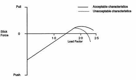
FIGURE 1
3.2 If stick force characteristics are marginally acceptable, it is desirable that there should be no reversal of normal control sensing, i.e. an aft movement of the control column should produce an aircraft motion in the nose-up direction and a change in aircraft load factor in the positive direction, and a forward movement of the control column should change the aircraft load factor in the negative direction.
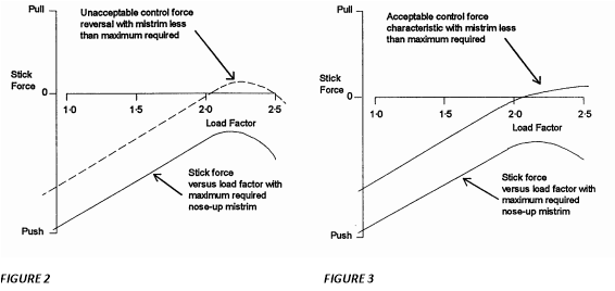
3.3 It is further intended that reversals of direction of stick force with negative stick-force gradients should not be permitted in any mistrim condition within the specified range of mistrim. If test results indicate that the curves of stick force versus normal acceleration with the maximum required mistrim have a negative gradient of speeds above VFC/MFC then additional tests may be necessary. The additional tests should verify that the curves of stick force versus load factor with mistrim less than the maximum required do not unacceptably reverse, as illustrated in the upper curve of Figure 2. Control force characteristics as shown in Figure 3, may be considered acceptable, provided that the control sensing does not reverse (see paragraph 3.2)
4 Probable Inadvertent Excursions beyond the Boundaries of the Buffet Onset Envelopes. CS 25.255(e) states that manoeuvring load factors associated with probable inadvertent excursions beyond the boundaries of the buffet onset envelopes determined under CS 25.251(e) need not be exceeded. It is intended that test flights need not be continued beyond a level of buffet which is sufficiently severe that a pilot would be reluctant to apply any further increase in load factor.
5 Use of the Longitudinal Trim System to Assist Recovery
5.1 CS 25.255(f) requires the ability to produce at least 1·5 g for recovery from an overspeed condition of VDF/MDF, using either the primary longitudinal control alone or the primary longitudinal control and the longitudinal trim system. Although the longitudinal trim system may be used to assist in producing the required normal acceleration, it is not acceptable for recovery to be completely dependent upon the use of this system. It should be possible to produce 1·2 g by applying not more than 556 N (125 lbf) of longitudinal control force using the primary longitudinal control alone.
5.2 Recovery capability is generally critical at altitudes where airspeed (VDF) is limiting. If at higher altitudes (on the MDF boundary) the manoeuvre capability is limited by buffeting of such an intensity that it is a strong deterrent to further increase in normal acceleration, some reduction of manoeuvre capability will be acceptable, provided that it does not reduce to below 1·3 g. The entry speed for flight test demonstrations of compliance with this requirement should be limited to the extent necessary to accomplish a recovery without exceeding VDF/MDF, and the normal acceleration should be measured as near to VDF/MDF as is practical.