
ED Decision 2016/010/R
(a) For the purpose of this CS-25 the aeroplane powerplant installation includes each component that –
(1) Is necessary for propulsion;
(2) Affects the control of the major propulsive units; or
(3) Affects the safety of the major propulsive units between normal inspections or overhauls.
(b) For each powerplant –
(1) The installation must comply with –
(i) The installation instructions provided under CS-E 20(d) and (e); and
(ii) The applicable provisions of this Subpart (see also AMC 20-1).
(2) The components of the installation must be constructed, arranged, and installed so as to ensure their continued safe operation between normal inspections or overhauls. (See AMC 25.901(b)(2).)
(3) The installation must be accessible for necessary inspections and maintenance; and
(4) The major components of the installation must be electrically bonded to the other parts of the aeroplane. (See AMC 25.901(b)(4).)
(c) The powerplant installation must comply with CS 25.1309, except that the effects of the following need not comply with CS 25.1309(b):
(1) Engine case burn through or rupture;
(2) Uncontained engine rotor failure; and
(3) Propeller debris release.
(See AMC 25.901(c) Safety Assessment of Powerplant Installations and AMC 25-24: Sustained Engine Imbalance)
[Amdt 25/1]
[Amdt 25/3]
[Amdt 25/8]
[Amdt 25/18]
AMC 25.901(b)(2) Assembly of Components
ED Decision 2003/2/RM
The objectives of CS 25.671(b) should be satisfied with respect to powerplant systems, where the safety of the aeroplane could otherwise be jeopardised.
AMC 25.901(b)(4) Electrical Bonding
ED Decision 2003/2/RM
Where the engine is not in direct electrical contact with its mounting, the engine should be electrically connected to the main earth system by at least two removable primary conductors, one on each side of the engine.
AMC 25.901(c) Safety Assessment of Powerplant Installations
ED Decision 2005/006/R
1. PURPOSE. This Acceptable Means of Compliance (AMC) describes an acceptable means for showing compliance with the requirements of CS 25.901(c). This document describes a method of conducting a “System Safety Assessment” of the powerplant installation as a means for demonstrating compliance. This guidance is intended to supplement the engineering and operational judgement that must form the basis of any compliance findings. The guidance provided in this document is meant for aeroplane manufacturers, modifiers, foreign regulatory authorities, and EASA Large Aeroplane type certification engineers. Like all AMC material, this AMC is not, in itself, mandatory, and does not constitute a requirement. It is issued to describe an acceptable means, but not the only means, for demonstrating compliance with the powerplant installation requirements for Large Aeroplanes. Terms such as “shall” and “must” are used only in the sense of ensuring applicability of this particular method of compliance when the acceptable method of compliance described in this document is used.
2. RELATED CERTIFICATION SPECIFICATIONS. CS 25.571, CS 25.901, CS 25.903, CS 25.933, CS 25.1309, and CS 25.1529; CS E-50 and E-510, CS P-150 and P-230.
3. APPLICABILITY. The guidance provided in this document applies to powerplant installations on Large Aeroplanes that are subject to the requirements of CS 25.901. This guidance specifically concerns demonstrating compliance with the requirements of CS 25.901(c), which states:
“(c) The powerplant installation must comply with CS 25.1309, except that the effects of the following need not comply with CS 25.1309(b):
(1) Engine case burn through or rupture;
(2) Uncontained engine rotor failure; and
(3) Propeller debris release.”
CS 25.901(c) is intended to provide an overall safety assessment of the powerplant installation that is consistent with the requirements of CS 25.1309, while accommodating unique powerplant installation compliance policies. It is intended to augment rather than replace other applicable CS-25 design and performance standards for Large Aeroplanes.
In accommodating unique policies related to powerplant compliance, EASA has determined that specific guidance relative to demonstrating compliance with CS 25.1309(b) is needed; such guidance is contained in this AMC. (No unique compliance requirements for CS 25.1309(a) and (c) are required for powerplant installations.)
Wherever this AMC indicates that compliance with other applicable requirements has been accepted as also meeting the intent of CS 25.901(c) for a specific failure condition, no additional dedicated safety analysis is required. Where this AMC may conflict with AMC 25.1309 (“System Design and Analysis”), this AMC shall take precedence for providing guidance in demonstrating compliance with CS 25.901(c).
When assessing the potential hazards to the aircraft caused by the powerplant installation, the effects of an engine case rupture, uncontained engine rotor failure, engine case burn-through, and propeller debris release are excluded from CS 25.901(c)/CS 25.1309. The effects and rates of these failures are minimised by compliance with CS-E, Engines; CS-P, Propellers; CS 25.903(d)(1), CS 25.905(d), and CS 25.1193.
Furthermore, the effects of encountering environmental threats or other operating conditions more severe than those for which the aircraft is certified (such as volcanic ash or operation above placard speeds) need not be considered in the CS 25.901(c)/CS 25.1309 compliance process. However, if a failure or malfunction can affect the subsequent environmental qualification or other operational capability of the installation, this effect should be accounted for in the CS 25.901(c)/CS 25.1309 assessment.
The terms used in this AMC are intended to be identical to those used in AMC 25.1309.
4. BACKGROUND.
JAR-25 was the Joint Aviation Authorities Airworthiness Code for Large Aeroplanes. It was developed from the U.S. Federal Aviation Regulations Part 25 (FAR 25) during the 1970s. Early versions (Changes) of JAR-25 consisted of only the differences from FAR 25.
In 1976, JAR-25 Change 3 was published and introduced, for the first time, requirement JAR 25.1309 and ACJ Nos. 1 to 7 to JAR 25.1309. Requirement JAR 25.1309 was almost the same as the (then) existing FAR regulation (Amdt. 25-37), but the advisory material given in the ACJ provided interpretation of and acceptable means of compliance with, the requirement. Specific advice was given on how to show that the inverse relationship existed between the criticality of the Failure Condition and its probability of occurrence.
JAR-25, Change 3, did not include any specific JAR-25 requirement for powerplant installation safety assessment and so FAR 25.901(c) was also valid for JAR-25. FAR 25.901(c) text (Amdt. 25-23, Effective 8 May 1970) stated:
“25.901 Installation
(c) The powerplant installation must comply with § 25.1309”.
At Change 4 of JAR-25, effective 19 July 1978, JAR 25.901(c) was introduced using the same FAR 25 words as shown above (viz.):
“JAR 25.901 Installation
(c) The power-plant installation must comply with JAR 25.1309.”
However, at about that time, the FAA had been reviewing a proposal to revise FAR 25.901(c), to introduce the wording “… no single failure or probable combination …”. This revised text was introduced at Amdt. 25-40, effective 2 May 1977.
The revisions introduced by Amdt. 25-40 were reviewed by the JAR-25 Study Groups and in two letters (Refs.: JAR/JET/2416/BT dated 21 July 1977 and JAR/JET/2467/BT dated 21 October 1977), the JAR-25 Powerplant Study Group recommended that, for JAR 25.901(c), the text should remain the same as the pre-Amdt. 25-40 version of FAR 25.901(c).
Since that time, JAR 25.901(c) and CS 25.901(c) have continued to refer to JAR / CS 25.1309 and for EASA/JAA, powerplant installations have been treated in the same way as for other aircraft systems when assessing the effects of failures and malfunctions.
One traditional exception to this has been the assessment of hazards resulting from an engine rotor failure. Previous ACJ No. 1 to JAR 25.1309 allowed for an explicit exception to the quantitative objective for a given catastrophic failure condition, for cases where the state of the art does not permit it to be achieved. This is the case for engine rotor failure and the ‘minimisation of hazard’ requirement of CS 25.903(d)(1) has been used instead of CS 25.1309 to cover this risk.
5. GENERAL SYSTEM SAFETY ASSESSMENT GUIDANCE.
Compliance with CS 25.901(c)/CS 25.1309 may be shown by a System Safety Assessment (SSA) substantiated by appropriate testing and/or comparable service experience. Such an assessment may range from a simple report that offers descriptive details associated with a failure condition, interprets test results, compares two similar systems, or offers other qualitative information; to a detailed failure analysis that may include estimated numerical probabilities.
The depth and scope of an acceptable SSA depend on:
— the complexity and criticality of the functions performed by the system(s) under consideration,
— the severity of related failure conditions,
— the uniqueness of the design and extent of relevant service experience,
— the number and complexity of the identified causal failure scenarios, and
— the detectability of contributing failures.
The SSA criteria, process, analysis methods, validation and documentation should be consistent with the guidance material contained in AMC 25.1309. Wherever there is unique guidance specifically for powerplant installations, this is delineated in Section 6, below.
In carrying out the SSA for the powerplant installation for CS 25.901(c)/CS 25.1309, the results of the engine (and propeller) failure analyses (reference CS P-150 and CS E-510) should be used as inputs for those powerplant failure effects that can have an impact on the aircraft. However, the SSA undertaken in response to CS-E and CS-P may not address all the potential effects that an engine and propeller as installed may have on the aircraft.
For those failure conditions covered by analysis under CS-E and CS-P, and for which the installation has no effect on the conclusions derived from these analyses, no additional analyses will be required to demonstrate compliance to CS 25.901(c)/CS 25.1309.
The effects of structural failures on the powerplant installation, and vice versa, should be carefully considered when conducting system safety assessments:
a. Effects of structural failures on powerplant installation. The powerplant installation must be shown to comply with CS 25.901(c) following structural failures that are anticipated to occur within the fleet life of the aeroplane type. This should be part of the assessment of powerplant installation failure condition causes.
Examples of structural failures that have been of concern in previous powerplant installations are:
(1) Thrust reverser restraining load path failure that may cause a catastrophic inadvertent deployment.
(2) Throttle quadrant framing or mounting failure that causes loss of control of multiple engines.
(3) Structural failures in an avionics rack or related mounting that cause loss of multiple, otherwise independent, powerplant functions/components/systems.
b. Effects of powerplant installation failures on structural elements. Any effect of powerplant installation failures that could influence the suitability of affected structures, should be identified during the CS 25.901(c) assessment and accounted for when demonstrating compliance with the requirements of CS-25, Subpart C (“Structure”) and D (“Design and Construction”). This should be part of the assessment of powerplant installation failure condition effects.
Some examples of historical interdependencies between powerplant installations and structures include:
(1) Fuel system failures that cause excessive fuel load imbalance.
(2) Fuel vent, refuelling, or feed system failures that cause abnormal internal fuel tank pressures.
(3) Engine failures that cause excessive loads/vibration.
(4) Powerplant installation failures that expose structures to extreme temperatures or corrosive material.
6. SPECIFIC CS 25.901(c) SYSTEM SAFETY ASSESSMENT GUIDANCE.
This section provides compliance guidance unique to powerplant installations.
a. Undetected Thrust Loss. The SSA discussed in Section 5 should consider undetected thrust loss and its effect on aircraft safety. The assessment should include an evaluation of the failure of components and systems that could cause an undetected thrust loss, except those already accounted for by the approved average-to-minimum engine assessment.
(1) In determining the criticality of undetected thrust losses from a system design and installation perspective, the following should be considered:
(i) Magnitude of the thrust loss,*
(ii) Direction of thrust,
(iii) Phase of flight, and
(iv) Impact of the thrust loss on aircraft safety.
(*Although it is common for safety analyses to consider the total loss of one engine's thrust, a small undetected thrust loss that persists from the point of take-off power set could have a more significant impact on the accelerate/stop distances and take-off flight path/obstacle clearance capability than a detectable single engine total loss of thrust failure condition at V1)
(2) In addition, the level at which any thrust loss becomes detectable should be validated. This validation is typically influenced by:
(i) Impact on aircraft performance and handling,
(ii) Resultant changes in powerplant indications,
(iii) Instrument accuracy and visibility,
(iv) Environmental and operating conditions,
(v) Relevant crew procedures and capabilities, etc.
(3) Reserved.
b. Detected Thrust Loss. While detectable engine thrust losses can range in magnitude from a few percent to 100% of total aircraft thrust, the total loss of useful thrust (in-flight shutdown/IFSD) of one or more engines usually has the largest impact on aircraft capabilities and engine-dependent systems. Furthermore, single and multiple engine IFSD’s tend to be the dominant thrust loss-related failure conditions for most powerplant installations. In light of this, the guidance in this AMC focuses on the IFSD failure conditions. The applicant must consider other engine thrust loss failure conditions, as well, if they are anticipated to occur more often than the IFSD failure condition, or if they are more severe than the related IFSD failure condition.
(1) Single Engine IFSD. The effects of any single engine thrust loss failure condition, including IFSD, on aircraft performance, controllability, manoeuvrability, and crew workload are accepted as meeting the intent of CS 25.901(c) if compliance is also demonstrated with:
— CS 25.111 (“Take-off path”),
— CS 25.121 (“Climb: one-engine-inoperative”), and
— CS 25.143 (“Controllability and Manoeuvrability -- General”).
(i) Nevertheless, the effects of an IFSD on other aircraft systems or in combination with other conditions also must be assessed as part of showing compliance with CS 25.901(c)/CS 25.1309. In this case, it should be noted that a single engine IFSD can result from any number of single failures, and that the rate of IFSD’s range from approximately 1x10⁻⁴ to 1x10⁻⁵ per engine flight hour. This rate includes all failures within a typical powerplant installation that affect one -- and only one -- engine. Those failures within a typical powerplant that can affect more than one engine are described in Section 6.b.(2), below.
(ii) If an estimate of the IFSD rate is required for a specific turbine engine installation, any one of the following methods is suitable for the purposes of complying with CS 25.901(c)/ CS 25.1309(b):
(A) Estimate the IFSD rate based on service experience of similar powerplant installations;
(B) Perform a bottom-up reliability analysis using service, test, and any other relevant experience with similar components and/or technologies to predict component failure modes and rates; or
(C) Use a conservative value of 1x10⁻⁴ per flight hour.
(iii) If an estimate of the percentage of these IFSD’s for which the engine is restartable is required, the estimate should be based on relevant service experience.
(iv) The use of the default value delineated in paragraph 6.b.(1)(ii)(C) is limited to traditional turbine engine installations. However, the other methods (listed in 6.b.(1)(ii)(A) and (B), above) are acceptable for estimating the IFSD rates and restartability for other types of engines, such as some totally new type of engine or unusual powerplant installation with features such as a novel fuel feed system. In the case of new or novel components, significant non-service experience may be required to validate the reliability predictions. This is typically attained through test and/or technology transfer analysis.
(v) Related issues that should be noted here are:
(A) CS 25.901(b)(2) sets an additional standard for installed engine reliability. This requirement is intended to ensure that all technologically feasible and economically practical means are used to assure the continued safe operation of the powerplant installation between inspections and overhauls.
(B) The effectiveness of compliance with CS 25.111, CS 25.121 and CS 25.143 in meeting the intent of CS 25.901(c) for single engine thrust loss is dependent on the accuracy of the human factors assessment of the crew’s ability to take appropriate corrective action. For the purposes of compliance with CS 25.901(c) in this area, it may be assumed that the crew will take the corrective actions called for in the aeroplane flight manual procedures and associated approved training.
(2) Multiple Engine IFSD. Typical engine IFSD rates may not meet the AC 25.1309-1B guidance that calls for 1 x 10⁻⁹ per hour for a catastrophic multiple engine IFSD. However, engine IFSD rates been part of the historically-accepted service experience upon which that guidance was based, and these IFSD rates are continuously improving. Consequently:
(i) Current typical turbine engine IFSD rates, and the resulting possibility of multiple independent IFSD’s leading to a critical power loss, are considered inherently acceptable for compliance with CS 25.901(c) without the need for quantitative assessment.
(ii) Nevertheless, some combinations of failures within aircraft systems common to multiple engines may cause a catastrophic multiple engine thrust loss. These should be assessed to ensure that they meet the extremely improbable criteria. Systems to be considered include:
— fuel system,
— air data system,
— electrical power system,
— throttle assembly,
— engine indication systems, etc.
(iii) The means of compliance described above is only valid for turbine engines, and for engines that can demonstrate equivalent reliability to turbine engines, using the means outlined in Section 6.a. of this AMC. The approach to demonstrating equivalent reliability should be discussed early in the program with the Agency on a case-by-case basis.
c. Automatic Take-off Thrust Control System. CS-25, Appendix I [“Automatic Take-off Thrust Control System (ATTCS)”], specifies the minimum reliability levels for these automatic systems. In addition to showing compliance with these reliability levels for certain combinations of failures, other failure conditions that can arise as a result of introducing such a system must be shown to comply with CS 25.901(c)/CS 25.1309.
d. Thrust Management Systems. A System Safety Assessment is essential for any aeroplane system that aids the crew in managing engine thrust (i.e., computing target engine ratings, commanding engine thrust levels, etc.). As a minimum, the criticality and failure hazard classification must be assessed. The system criticality will depend on:
— the range of thrust management errors it could cause,
— the likelihood that the crew will detect these errors and take appropriate corrective action, and
— the severity of the effects of these errors with and without crew intervention.
The hazard classification will depend on the most severe effects anticipated from any system. The need for more in-depth analysis will depend upon the systems complexity, novelty, initial failure hazard classification, relationship to other aircraft systems, etc.
(1) Automated thrust management features, such as autothrottles and target rating displays, traditionally have been certified on the basis that they are only conveniences to reduce crew workload and do not relieve the crew of any responsibility for assuring proper thrust management. In some cases, malfunctions of these systems can be considered to be minor, at most. However, for this to be valid, even when the crew is no longer directly involved in performing a given thrust management function, the crew must be provided with information concerning unsafe system operating conditions to enable them to take appropriate corrective action.
(2) Consequently, when demonstrating compliance with CS 25.901(c)/CS 25.1309, failures within any automated thrust management feature which, if not detected and properly accommodated by crew action, could create a catastrophe should be either:
(i) considered a catastrophic failure condition when demonstrating compliance with CS 25.901(c)/CS 25.1309(b); or
(ii) considered an unsafe system operating condition when demonstrating compliance with the warning requirements of CS 25.1309(c).
e. Thrust Reverser. Compliance with CS 25.933(a) (“Reversing systems”) provides demonstration of compliance with CS 25.901(c)/CS 25.1309 for the thrust reverser in-flight deployment failure conditions. A standard CS 25.901(c)/CS 25.1309 System Safety Assessment should be performed for any other thrust reverser-related failure conditions.
7. TYPICAL FAILURE CONDITIONS FOR POWERPLANT SYSTEM INSTALLATIONS.
The purpose of this section is to provide a list of typical failure conditions that may be applicable to a powerplant system installation. This list is by no means all-encompassing, but it captures some failure conditions that have been of concern in previous powerplant system installations. The specific failure conditions identified during the preliminary SSA for the installation should be reviewed against this list to assist in ensuring that all failure conditions have been identified and properly addressed.
As stated previously in this AMC, the assessment of these failure conditions may range from a simple report that offers descriptive details associated with a failure condition, interprets test results, compares two similar systems, or offers other qualitative information; to a detailed failure analysis that may include estimated numerical probabilities. The assessment criteria, process, analysis methods, validation, and documentation should be consistent with the guidance material contained in AMC 25.1309.
a. Fire Protection System - Failure Conditions:
(1) Loss of detection in the presence of a fire.
(2) Loss of extinguishing in the presence of a fire.
(3) Loss of fire zone integrity in the presence of a fire.
(4) Loss of flammable fluid shut-off or drainage capability in the presence of a fire.
(5) Creation of an ignition source outside a fire zone but in the presence of flammable fluids.
b. Fuel System -- Failure Conditions:
(1) Loss of fuel feed/fuel supply.
(2) Inability to control lateral and longitudinal balance.
(3) Hazardously misleading fuel indications.
(4) Loss of fuel tank integrity.
(5) Loss of fuel jettison.
(6) Uncommanded fuel jettison.
c. Powerplant Ice Protection - Failure Conditions:
(1) Loss of propeller, inlet, engine, or other powerplant ice protection on multiple powerplants when required.
(2) Loss of engine/powerplant ice detection.
(3) Activation of engine inlet ice protection above limit temperatures.
d. Propeller Control - Failure Conditions:
(1) Inadvertent fine pitch (overspeed, excessive drag).
(2) Inadvertent coarse pitch (over-torque, thrust asymmetry)
(3) Uncommanded propeller feathering.
(4) Failure to feather.
(5) Inadvertent application of propeller brake in flight.
(6) Unwanted reverse thrust (pitch).
e. Engine Control and Indication -- Failure Conditions:
(1) Loss of thrust.
(2) Loss of thrust control, including asymmetric thrust, thrust increases, thrust decreases, thrust fail fixed, and unpredictable engine operation.
(3) Hazardously misleading display of powerplant parameter(s).
f. Thrust Reverser - Failure Conditions:
(1) Inadvertent deployment of one or more reversers.
(2) Failure of one or more reversers to deploy when commanded.
(3) Failure of reverser component restraints (i.e., opening of D-ducts in flight, release of cascades during reverser operation, etc.).
[Amdt No: 25/1]
ED Decision 2016/016/R
(See AMC 25.903)
(a) Engine type certification.
(1) reserved
(2) Any engine not certificated to CS-E must be shown to comply with CS-E 790 and CS-E 800 or be shown to have a foreign object ingestion service history in similar installation locations which has not resulted in any unsafe condition.
(3) Any engine not certificated to CS–E must be shown to comply with CS–E 780 or be shown to have an ice accumulation service history in similar installation locations which has not resulted in any unsafe conditions.
(b) Engine isolation. The powerplants must be arranged and isolated from each other to allow operation, in at least one configuration, so that the failure or malfunction of any engine, or of any system that can affect the engine, will not –
(1) Prevent the continued safe operation of the remaining engines; or
(2) Require immediate action by any crew member for continued safe operation.
(c) Control of engine rotation. There must be means for stopping the rotation of any engine individually in flight, except that, for turbine engine installations, the means for stopping the rotation of any engine need be provided only where continued rotation could jeopardise the safety of the aeroplane. Each component of the stopping system on the engine side of the firewall that might be exposed to fire must be at least fire resistant. If hydraulic propeller feathering systems are used for this purpose, the feathering lines must be at least fire-resistant under the operating conditions that may be expected to exist during feathering.
(d) Turbine engine installations. For turbine engine installations –
(1) Design precautions must be taken to minimise the hazards to the aeroplane in the event of an engine rotor failure or of a fire originating within the engine which burns through the engine case. (See AMC 25.903(d)(1) and AMC 20-128A.)
(2) The powerplant systems associated with engine control devices, systems, and instrumentation, must be designed to give reasonable assurance that those engine operating limitations that adversely affect turbine rotor structural integrity will not be exceeded in service.
(e) Restart capability.
(1) Means to restart any engine in flight must be provided.
(2) An altitude and airspeed envelope must be established for in-flight engine restarting, and each engine must have a restart capability within that envelope. (See AMC 25.903(e)(2).)
(3) For turbine engine powered aeroplanes, if the minimum windmilling speed of the engines, following the in-flight shutdown of all engines, is insufficient to provide the necessary electrical power for engine ignition, a power source independent of the engine-driven electrical power generating system must be provided to permit in-flight engine ignition for restarting.
[Amdt 25/16]
[Amdt 25/18]
AMC 25.903(d)(1) Torching Flames
ED Decision 2003/2/RM
Where design precautions to minimise the hazard in the event of a combustion chamber burnthrough involve the use of torching flame resistant components and/or materials, satisfaction of the standards prescribed in British Standards Institution Specification 3G100: Part 2: Section 3: Sub-section 3.13, dated December 1973, is acceptable.
ED Decision 2003/2/RM
1 General
1.1 In general the relight envelope required in CS 25.903(e)(2) may consist of two zones –
a. One zone where the engine is rotated by windmilling at or beyond the minimum rpm to effect a satisfactory relight, and
b. Another zone where the engine is rotated with assistance of the starter at or beyond the minimum rpm to effect a satisfactory relight.
1.2 The minimum acceptable relight envelope is defined in paragraph 2.
2 Envelope of Altitude and Airspeed
2.1 Sufficient flight tests should be made over the range of conditions detailed in 2.2 and 2.3, to establish the envelope of altitude and airspeed for reliable engine restarts, taking into account the results of restart tests completed by the engine constructor on the same type of engine in an altitude test facility or flying test bed, if available, and the experience accumulated in other aircraft with the same engine. The effect of engine deterioration in service should be taken into account.
2.2 Altitude and Configuration. From sea-level to the maximum declared restarting altitude in all appropriate configurations likely to affect restarting, including the emergency descent configuration.
2.3 Airspeed. From the minimum to the maximum declared airspeed at all altitudes up to the maximum declared engine restarting altitude. The airspeed range of the declared relight envelope should cover at least 30 kt.
2.4 Delay Tests. The tests referred to in paragraph 2.2 should include the effect on engine restarting performance of delay periods between engine shut-down and restarting of –
a. Up to two minutes, and
b. At least fifteen minutes or until the engine oil temperatures are stabilised at their cold soak value.
CS 25.904 Automatic Takeoff Thrust Control System (ATTCS)
ED Decision 2003/2/RM
Aeroplanes equipped with an engine power control system that automatically resets the power or thrust on the operating engine(s) when any engine fails during the takeoff must comply with the requirements of Appendix I.
ED Decision 2016/010/R
(See AMC 25.905)
(a) reserved
(b) Engine power and propeller shaft rotational speed may not exceed the limits for which the propeller is certificated. (See CS-P 50.)
(c) Each component of the propeller blade pitch control system must meet the requirements of CS-P 420.
(d) Design precautions must be taken to minimise the hazards to the aeroplane in the event a propeller blade fails or is released by a hub failure. The hazards which must be considered include damage to structure and critical systems due to impact of a failed or released blade and the unbalance created by such failure or release. (See AMC 25.905(d).)
[Amdt 25/3]
[Amdt 25/18]
AMC 25.905(d) Release of Propeller Debris
ED Decision 2003/2/RM
1 Propeller Installation. Design features of the propeller installation, including its control system, which are considered to influence the occurrence of propeller debris release and/or mode of such a failure should be taken into account when assessing the aeroplane against CS 25.905(d).
2 Aeroplane Design Conditions
2.1 Impact Damage Zone. All practical precautions should be taken in the aeroplane design to minimise, on the basis of good engineering judgement, the risk of Catastrophic Effects due to the release of part of, or a complete propeller blade. These precautions should be taken within an impact zone defined by the region between the surfaces generated by lines passing through the centre of the propeller hub making angles of at least five degrees forward and aft of the plane of rotation of each propeller. Within this zone at least the following should be considered.
a. The vulnerability of critical components and systems (e.g. location, duplication, separation, protection); and
b. The fire risk in the event of flammable fluid release in association with potential ignition sources (e.g. location, protection, shut-off means).
2.2 Other Considerations. Consideration should be given to the effects on the aeroplane resulting from –
a. The likely out of balance forces due to the release of part of, or a complete propeller blade; and
b. Loss of a complete propeller.
ED Decision 2007/010/R
(See CS-P 530 and CS-P 550.)
(a) The magnitude of the propeller blade vibration stresses under any normal condition of operation must be determined by actual measurement or by comparison with similar installations for which these measurements have been made.
(b) The determined vibration stresses may not exceed values that have been shown to be safe for continuous operation.
[Amdt 25/3]
AMC 25.907 Propeller vibration
ED Decision 2021/015/R
EASA accepts Federal Aviation Administration (FAA) Advisory Circular (AC) 20-66B ‘Propeller Vibration and Fatigue’, of 24 March 2011, as an acceptable means of compliance with CS 25.907 regarding the evaluation of vibratory stresses on propellers. The applicant should use in that evaluation fatigue and structural data that is obtained in accordance with the Certification Specifications and Acceptable Means of Compliance for Propellers (CS-P).
When investigating the actual vibration behaviour of each propeller, the applicant should include the operating conditions that correspond to descent with the power levers at flight idle position and with speeds around maximum operating limit speed (VMO). Experience has shown that such conditions may cause cyclic loads and vibrations that may exert excessive stress on some parts of the propeller. As aerodynamic loads differ depending on the position of the engine-propeller assembly on the aeroplane, the applicant should investigate the propellers’ vibration behaviour at all engine-propeller assembly positions.
[Amdt No: 25/27]
ED Decision 2016/010/R
Unless smaller clearances are substantiated, propeller clearances with the aeroplane at maximum weight, with the most adverse centre of gravity, and with the propeller in the most adverse pitch position, may not be less than the following:
(a) Ground clearance. There must be a clearance of at least 18 cm (7 inches) (for each aeroplane with nose wheel landing gear) or (23 cm 9 inches (for each aeroplane with tail-wheel landing gear) between each propeller and the ground with the landing gear statically deflected and in the level take-off, or taxying attitude, whichever is most critical. In addition, there must be positive clearance between the propeller and the ground when in the level take-off attitude with the critical tyre(s) completely deflated and the corresponding landing gear strut bottomed.
(b) Reserved.
(c) Structural clearance. There must be –
(1) At least 25 mm (1·0 inches) radial clearance between the blade tips and the aeroplane structure, plus any additional radial clearance necessary to prevent harmful vibration;
(2) At least 13 mm (0·5 inches) longitudinal clearance between propeller blades or cuffs and stationary parts of the aeroplane; and
(3) Positive clearance between other rotating parts of the propeller or spinner and stationary parts of the aeroplane.
[Amdt 25/18]
ED Decision 2016/010/R
(See AMC 25.929)
(a) If certification for flight in icing conditions is sought, there must be a means to prevent or remove hazardous ice accumulations that could form in the icing conditions defined in Appendices C and O on propellers or on accessories where ice accumulation would jeopardise engine performance (see AMC 25.929(a)).
(b) If combustible fluid is used for propeller de-icing, CS 25.1181 to CS 25.1185 and CS 25.1189 apply.
[Amdt 25/16]
[Amdt 25/18]
AMC 25.929(a) Propeller de-icing
ED Decision 2016/010/R
1. Analysis.
The applicant should perform an analysis that:
(1) substantiates ice protection coverage in relation to chord length and span.
(2) substantiates the ice protection system power density.
(3) consider the effect of intercycle ice accretions and potential for propeller efficiency degradation for all flight phases.
(4) assess the different propeller Ice Protection System failure modes which are not extremely improbable and leading to the:
(i) highest propeller performance level degradation, and
(ii) highest propeller vibration levels taking also into account possible ice shedding.
(5) assess the impact of ice released by the propeller on the vibration levels, the adjacent components (if any) and the aircraft structure, both for normal operation and in the different propeller de-icing system failure modes.
Similarity to prior designs with successful service histories in icing may be used to show compliance. A demonstration of similarity requires an evaluation of both system and installation differences. The applicant should show specific similarities in the areas of physical, functional, thermodynamic, pneumatic, and aerodynamic characteristics as well as in environmental exposure. The analysis should show that propeller installation, operation, and effect on the aeroplane’s performance and handling are equivalent to that of the same or similar propeller in the previously approved configuration. Differences should be evaluated for their effect on IPS functionality and on safe flight in icing. If there is uncertainty about the effects of the differences, the applicant should conduct additional tests and/or analysis as necessary and appropriate to resolve the open issues.
For showing compliance with the CS-25 certification specifications relative to SLD icing conditions represented by Appendix O, the applicant may use a comparative analysis. AMC 25.1420(f) provides guidance for comparative analysis.
2. Compliance Tests.
2.1 Surface temperature measurements should be made and monitored in dry air flight testing. These measurements are useful for correlating analytically predicted dry air temperatures with actual temperatures, and as a general indicator that the system is functioning and that each de-icer is heating. It is suggested that system current, brush block voltage (i.e., between each input brush and the ground brush) and system duty cycles be monitored to ensure that adequate power is applied to the de-icers.
2.2 System operation should be checked throughout the full rotation speed range. and propeller cyclic pitch range expected during flight in icing. Additionally, if the propeller Ice Protection System is regulated based on different outside parameters such as temperature, then system operation should also be checked against those parameters. All significant vibrations should be investigated.
2.3 The analysis assessing the effect of intercycle ice accretions and potential for propeller efficiency degradation should be adequately validated by tests.
2.4 The Ice Protection System failure modes determined in 1.4 above should be adequately validated by tests.
2.5 The applicant should consider the maximum temperatures a composite propeller blade may be subjected to when de-icers are energized. It may be useful to monitor de-icer bond-side temperatures. When performing this evaluation, the most critical conditions should be investigated (e.g., aeroplane on the ground; propellers not rotating) on a hot day with the system inadvertently energized.
2.6 Shedding procedures and post failure procedures mentioned in the AFM should be demonstrated by test.
3. Runback Ice.
Water not evaporated by thermal ice protection systems and unfrozen water in near-freezing conditions (or in conditions when the freezing fraction is less than one) may run aft and form runback ice. This runback ice can then accumulate additional mass from direct impingement. Computer codes may be unable to estimate the characteristics of the runback water or resultant ice shapes (rivulets or thin layers), but some codes may be able to estimate the mass of the runback ice. Thus runback ice should be determined experimentally, or the mass determined by computer codes with assumptions about runback extent and thickness similar to those used successfully with prior models. The runback ice should be determined both for normal operation and for propeller Ice Protection System failure modes when not operating in the predefined cycles.
The applicant should consider potential hazards resulting from the loss of propeller performance, the increased vibration level and the runback ice shedding.
[Amdt 25/16]
[Amdt 25/18]
ED Decision 2020/001/R
(See AMC 25.933)
(a) For turbojet reversing systems:
(1) Each system intended for ground operation only must be designed so that either:
(i) The aeroplane can be shown to be capable of continued safe flight and landing during and after any thrust reversal in flight; or
(ii) It can be demonstrated that any in-flight thrust reversal complies with CS 25.1309(b).
(See AMC 25.933(a)(1))
(2) Each system intended for inflight use must be designed so that no unsafe condition will result during normal operation of the system, or from any failure (or reasonably likely combination of failures) of the reversing system, under any anticipated condition of operation of the aeroplane including ground operation. Failure of structural elements need not be considered if the probability of this kind of failure is extremely remote.
(3) Each system must have means to prevent the engine from producing more than idle thrust when the reversing system malfunctions, except that it may produce any greater forward thrust that is shown to allow directional control to be maintained, with aerodynamic means alone, under the most critical reversing condition expected in operation.
(b) For propeller reversing systems:
(1) Each system intended for ground operation only must be designed so that no single failure (or reasonably likely combination of failures) or malfunction of the system will result in unwanted reverse thrust under any expected operating condition. Failure of structural elements need not be considered if this kind of failure is extremely remote.
(2) Compliance with this paragraph may be shown by failure analysis or testing, or both, for propeller systems that allow propeller blades to move from the flight low-pitch position to a position that is substantially less than that at the normal flight low-pitch position. The analysis may include or be supported by the analysis made to show compliance with the requirements of CS-P 70 for the propeller and associated installation components.
[Amdt 25/1]
[Amdt 25/18]
[Amdt 25/24]
AMC 25.933(a)(1) Unwanted in-flight thrust reversal of turbojet thrust reversers
ED Decision 2020/001/R
1. PURPOSE.
This Acceptable Means of Compliance (AMC) describes various acceptable means, for showing compliance with the requirements of CS 25.933(a)(1), "Reversing systems", of CS-25. These means are intended to provide guidance to supplement the engineering and operational judgement that must form the basis of any compliance findings relative to in-flight thrust reversal of turbojet thrust reversers.
2. RELATED CERTIFICATION SPECIFICATIONS.
CS 25.111, CS 25.143, CS 25.251, CS 25.571, CS 25.901, CS 25.903, CS 25.1155, CS 25.1305, CS 25.1309, CS 25.1322 and CS 25.1529
3. APPLICABILITY.
The requirements of CS 25.933 apply to turbojet thrust reverser systems. CS 25.933(a) specifically applies to reversers intended for ground operation only, while CS 25.933(b) applies to reversers intended for both ground and in-flight use.
This AMC applies only to unwanted thrust reversal in flight phases when the landing gear is not in contact with the ground; other phases (i.e., ground operation) are addressed by CS 25.901(c) and CS 25.1309.
4. BACKGROUND.
4.a. General. Most thrust reversers are intended for ground operation only. Consequently, thrust reverser systems are generally sized and developed to provide high deceleration forces while avoiding foreign object debris (FOD) ingestion, aeroplane surface efflux impingement, and aeroplane handling difficulty during landing roll. Likewise, aircraft flight systems are generally sized and developed to provide lateral and directional controllability margins adequate for handling qualities, manoeuvrability requirements, and engine-out VMC lateral drift conditions.
In early turbojet aeroplane designs, the combination of control system design and thrust reverser characteristics resulted in control margins that were capable of recovering from unwanted in-flight thrust reversal even on ground-use-only reversers; this was required by the previous versions of CS 25.933.
As the predominant large aeroplane configuration has developed into the high bypass ratio twin engine-powered model, control margins for the in-flight thrust reversal case have decreased. Clearly, whenever and wherever thrust reversal is intended, the focus must remain on limiting any adverse effects of thrust reversal. However, when demonstrating compliance with CS 25.933(a) or CS 25.933(b), the Authority has accepted that applicants may either provide assurance that the aeroplane is controllable after an in-flight thrust reversal event or that the unwanted in-flight thrust reversal event will not occur.
Different historical forms of the rule have attempted to limit either the effect or the likelihood of unwanted thrust reversal during flight. However, experience has demonstrated that neither method is always both practical and effective. The current rule, and this related advisory material, are intended to allow either of these assurance methods to be applied in a manner which recognises the limitations of each, thereby maximising both the design flexibility and safety provided by compliance with the rule.
4.b. Minimising Adverse Effects. The primary purpose of reversing systems, especially those intended for ground operation only, is to assist in decelerating the aeroplane during landing and during an aborted take-off. As such, the reverser must be rapid-acting and must be effective in producing sufficient reverse thrust. These requirements result in design characteristics (actuator sizing, efflux characteristics, reverse thrust levels, etc.) that, in the event of thrust during flight, could cause significant adverse effects on aeroplane controllability and performance.
If the effect of the thrust reversal occurring in flight produces an unacceptable risk to continued safe flight and landing, then the reverser operation and de-activation system must be designed to prevent unwanted thrust reversal. Alternatively, for certain aeroplane configurations, it may be possible to limit the adverse impacts of unwanted thrust reversal on aeroplane controllability and performance such that the risk to continued safe flight and landing is acceptable (discussed later in this AMC).
For reversing systems intended for operation in flight, the reverser system must be designed to adequately protect against unwanted in-flight thrust reversal.
CS 25.1309 and CS 25.901(c) and the associated AMC (AMC 25.1309 and AMC 25.901(c) provide guidance for developing and assessing the safety of systems at the design stage. This methodology should be applied to the total reverser system, which includes:
— the reverser;
— the engine (if it can contribute to thrust reversal);
— the reverser motive power source;
— the reverser control system;
— the reverser command system in the cockpit; and
— the wiring, cable, or linkage system between the cockpit and engine.
Approved removal, deactivation, reinstallation, and repair procedures for any element in the reverser or related systems should result in a safety level equivalent to the certified baseline system configuration.
Qualitative assessments should be done, taking into account potential human errors (maintenance, aeroplane operation).
Data required to determine the level of the hazard to the aeroplane in case of in-flight thrust reversal and, conversely, data necessary to define changes to the reverser or the aeroplane to eliminate the hazard, can be obtained from service experience, test, and/or analysis. These data also can be used to define the envelope for continued safe flight.
There are many opportunities during the design of an aeroplane to minimise both the likelihood and severity of unwanted in-flight thrust reversal. These opportunities include design features of both the aeroplane and the engine/reverser system. During the design process, consideration should be given to the existing stability and control design features, while preserving the intended function of the thrust reverser system.
Some design considerations, which may help reduce the risk from in-flight thrust reversal, include:
4.b.(1) Engine location to:
(i) Reduce sensitivity to efflux impingement.
(ii) Reduce effective reverse thrust moment arms
4.b.(2) Engine/Reverser System design to:
(i) Optimise engine/reverser system integrity and reliability.
(ii) Rapidly reduce engine airflow (i.e. auto-idle) in the event of an unwanted thrust reversal. Generally, such a feature is considered a beneficial safety item. In this case, the probability and effect of any unwanted idle command or failure to provide adequate reverse thrust when selected should be verified to be consistent with AMC 25.1309 and AMC 25.901(c).
(iii) Give consideration to the aeroplane pitch, yaw, and roll characteristics.
(iv) Consider effective efflux diameter.
(v) Consider efflux area.
(vi) Direct reverser efflux away from critical areas of the aeroplane.
(vii) Expedite detection of unwanted thrust reversal, and provide for rapid compensating action within the reversing system.
(viii) Optimise positive aerodynamic stowing forces.
(ix) Inhibit in-flight thrust reversal of ground-use-only reversers, even if commanded by the flight crew.
(x) Consider incorporation of a restow capability for unwanted thrust reversal.
4.b.(3) Airframe/System design to:
(i) Maximise aerodynamic control capability.
(ii) Expedite detection of thrust reversal, and provide for rapid compensating action through other airframe systems.
(iii) Consider crew procedures and responses.
The use of formal «lessons learned»-based reviews early and often during design development may help avoid repeating previous errors and take advantage of previous successes.
5. DEFINITIONS.
The following definitions apply for the purpose of this AMC:
a. Catastrophic: see AMC 25.1309
b. Continued Safe Flight and Landing: The capability for continued controlled flight and safe landing at an airport, possibly using emergency procedures, but without requiring exceptional pilot skill or strength. Some aeroplane damage may be associated with a failure condition, during flight or upon landing.
c. Controllable Flight Envelope and Procedure: An area of the Normal Flight Envelope where, given an appropriate procedure, the aeroplane is capable of continued safe flight and landing following an in-flight thrust reversal.
d. Deactivated Reverser: Any thrust reverser that has been deliberately inhibited such that it is precluded from performing a normal deploy/stow cycle, even if commanded to do so.
e. Exceptional Piloting Skill and/or Strength: Refer to CS 25.143(c)(c) («Controllability and Manoeuvrability—General»).
f. Extremely Improbable: see AMC 25.1309
g. Extremely Remote: see AMC 25.1309
h. Failure: see AMC 25.1309
i. Failure Situation: All failures that result in the malfunction of one independent command and/or restraint feature that directly contributes to the top level Fault Tree Analysis event (i.e., unwanted in-flight thrust reversal). For the purpose of illustration, Figure 1, below, provides a fault tree example for a scenario of three «failure situations» leading to unwanted in-flight thrust reversal.
Figure 1: TOP EVENT
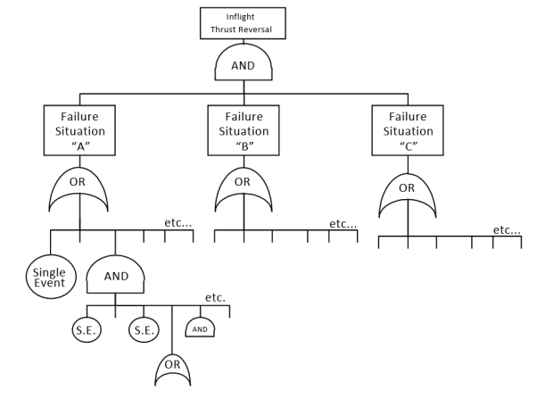
Reverser System with three independent command/restraint features shown for reference only.
j. Hazardous: see AMC 25.1309
k. In-flight: that part of aeroplane operation beginning when the wheels are no longer in contact with the ground during the take-off and ending when the wheels again contact the ground during landing.
l. Light Crosswind: For purposes of this AMC, a light crosswind is a 19 km/h (10 Kt). wind at right angles to the direction of take-off or landing which is assumed to occur on every flight.
m. Light Turbulence: Turbulence that momentarily causes slight, erratic changes in altitude and/or attitude (pitch, roll, and/or yaw), which is assumed to occur on every flight.
n. Major: see AMC 25.1309
o. Maximum exposure time: The longest anticipated period between the occurrence and elimination of the failure.
p. Normal Flight Envelope: An established boundary of parameters (velocity, altitude, angle of attack, attitude) associated with the practical and routine operation of a specific aeroplane that is likely to be encountered on a typical flight and in combination with prescribed conditions of light turbulence and light crosswind.
q. Pre-existing failure: Failure that can be present for more than one flight.
r. Thrust Reversal: A movement of all or part of the thrust reverser from the forward thrust position to a position that spoils or redirects the engine airflow.
s. Thrust Reverser System: Those components that spoil or redirect the engine thrust to decelerate the aeroplane. The components include:
— the engine-mounted hardware,
— the reverser control system,
— indication and actuation systems, and
— any other aeroplane systems that have an effect on the thrust reverser operation.
t. Turbojet thrust reversing system: Any device that redirects the airflow momentum from a turbojet engine so as to create reverse thrust. Systems may include:
— cascade-type reversers,
— target or clamshell-type reversers,
— pivoted-door petal-type reversers,
— deflectors articulated off either the engine cowling or aeroplane structure,
— targetable thrust nozzles, or
— a propulsive fan stage with reversing pitch.
u. Turbojet (or turbofan): A gas turbine engine in which propulsive thrust is developed by the reaction of gases being directed through a nozzle.
6. DEMONSTRATING COMPLIANCE WITH CS 25.933(a).
The following Sections 7 through 10 of this AMC provide guidance on specific aspects of compliance with CS 25.933(a), according to four different means or methods:
— Controllability (Section 7),
— Reliability (Section 8),
— Mixed controllability / reliability (Section 9),
— Deactivated reverser (Section 10).
7. «CONTROLLABILITY OPTION»: PROVIDE CONTINUED SAFE FLIGHT AND LANDING FOLLOWING ANY IN-FLIGHT THRUST REVERSAL.
The following paragraphs provide guidance regarding an acceptable means of demonstrating compliance with CS 25.933(a)(1).
7.a. General. For compliance to be established with CS 25.933(a) by demonstrating that the aeroplane is capable of continued safe flight and landing following any in-flight thrust reversal (the «controllability option» provided for under CS 25.933(a)(1)), the aspects of structural integrity, performance, and handling qualities must be taken into account. The level of accountability should be appropriate to the probability of in-flight thrust reversal, in accordance with the following sections.
To identify the corresponding failure conditions and determine the probability of their occurrence, a safety analysis should be carried out, using the methodology described in CS 25.1309. The reliability of design features, such as auto-idle and automatic control configurations critical to meeting the following controllability criteria, also should be considered in the safety analysis.
Appropriate alerts and/or other indications should be provided to the crew, as required by CS 25.1309(c) (Ref. AMC 25.1309).
The inhibition of alerts relating to the thrust reverser system during critical phases of flight should be evaluated in relation to the total effect on flight safety (Ref. AMC 25.1309).
Thrust reversal of a cyclic or erratic nature (e.g., repeated deploy/stow movement of the thrust reverser) should be considered in the safety analysis and in the design of the alerting/indication systems.
Input from the flight crew and human factors specialists should be considered in the design of the alerting and/or indication provisions.
The controllability compliance analysis should include the relevant thrust reversal scenario that could be induced by a rotorburst event.
When demonstrating compliance using this «controllability option» approach, if the aeroplane might experience an in-flight thrust reversal outside the «controllable flight envelope» anytime during the entire operational life of all aeroplanes of this type, then further compliance considerations as described in Section 9 («MIXED CONTROLLABILITY / RELIABILITY OPTION») of this AMC, below, should be taken into account.
7.b. Structural Integrity. For the «controllability option,» the aeroplane must be capable of successfully completing a flight during which an unwanted in-flight thrust reversal occurs. An assessment of the integrity of the aeroplane structure is necessary, including an assessment of the structure of the deployed thrust reverser and its attachments to the aeroplane.
In conducting this assessment, the normal structural loads, as well as those induced by failures and forced vibration (including buffeting), both at the time of the event and for continuation of the flight, must be shown to be within the structural capability of the aeroplane.
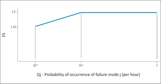
At the time of occurrence, starting from 1-g level flight conditions, at speeds up to VC, a realistic scenario, including pilot corrective actions, should be established to determine the loads occurring at the time of the event and during the recovery manoeuvre. The aeroplane should be able to withstand these loads multiplied by an appropriate factor of safety that is related to the probability of unwanted in-flight thrust reversal. The factor of safety is defined in Figure 2, below. Conditions with high lift devices deployed also should be considered at speeds up to the appropriate flap limitation speed.
Figure 2: Factor of safety at the time of occurrence
For continuation of the flight following in-flight thrust reversal, considering any appropriate reconfiguration and flight limitations, the following apply:
7.b.(1) Static strength should be determined for loads derived from the following conditions at speeds up to VC, or the speed limitation prescribed for the remainder of the flight:
(i) 70% of the limit flight manoeuvre loads; and separately
(ii) the discrete gust conditions specified in CS 25.341(a) (but using 40% of the gust velocities specified for VC).
7.b.(2) For the aeroplane with high lift devices deployed, static strength should be determined for loads derived from the following conditions at speeds up the appropriate flap design speed, or any lower flap speed limitation prescribed for the remainder of the flight:
(i) A balanced manoeuvre at a positive limit load factor of 1.4; and separately
(ii) the discrete gust conditions specified in CS 25.345(a)(2) (but using 40% of the gust velocities specified).
7.b.(3) For static strength substantiation, each part of the structure must be able to withstand the loads specified in sub-paragraph 7.b.(1) and 7.b.(2) of this paragraph, multiplied by a factor of safety depending on the probability of being in this failure state. The factor of safety is defined in Figure 3, below.
Figure 3: Factor of safety for continuation of flight
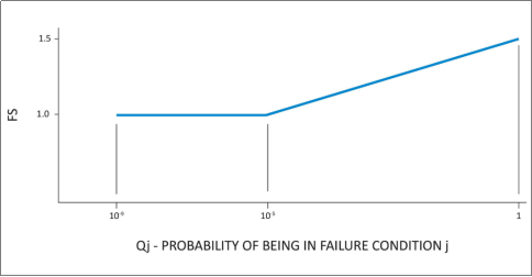
Qj = is the probability of being in the configuration with the unwanted in-flight thrust reversal
Qj = (Tj)(Pj) where:
Tj = average time spent with unwanted in-flight thrust reversal (in hours)
Pj = probability of occurrence of unwanted in-flight thrust reversal (per hour)
If the thrust reverser system is capable of being restowed following a thrust reversal, only those loads associated with the interval of thrust reversal need to be considered. Historically, thrust reversers have often been damaged as a result of unwanted thrust reversal during flight. Consequently, any claim that the thrust reverser is capable of being restowed must be adequately substantiated, taking into account this adverse service history.
7.c. Performance
7.c.(1) General Considerations: Most failure conditions that have an effect on performance are adequately accounted for by the requirements addressing a «regular» engine failure (i.e., involving only loss of thrust and not experiencing any reverser anomaly). This is unlikely to be the case for failures involving an unwanted in-flight thrust reversal, which can be expected to have a more adverse impact on thrust and drag than a regular engine failure. Such unwanted in-flight thrust reversals, therefore, should be accounted for specifically, to a level commensurate with their probability of occurrence.
The performance accountability that should be provided is defined in Sections 7.c.(2) and 7.c.(3) as a function of the probability of the unwanted in-flight thrust reversal. Obviously, for unwanted in-flight thrust reversals less probable than 1x10- 9 /fh, certification may be based on reliability alone, as described in Section 8 («RELIABILITY OPTION») of this AMC. Furthermore, for any failure conditions where unwanted in-flight thrust reversal would impact safety, the aeroplane must meet the safety/reliability criteria delineated in CS 25.1309.
7.c.(2) Probability of unwanted in-flight thrust reversal greater than 1x10⁻⁷/fh: Full performance accountability must be provided for the more critical of a regular engine failure and an unwanted in-flight thrust reversal.
To determine if the unwanted in-flight thrust reversal is more critical than a regular engine failure, the normal application of the performance requirements described in CS-25, Subpart B, as well as the applicable operating requirements, should be compared to the application of the following criteria, which replace the accountability for a critical engine failure with that of a critical unwanted in-flight thrust reversal:
— CS 25.111, «Take-off path»: The takeoff path should be determined with the critical unwanted thrust reversal occurring at VLOF instead of the critical engine failure at VEF. No change to the state of the engine with the thrust reversal that requires action by the pilot may be made until the aircraft is 122 m (400 ft) above the takeoff surface.
— CS 25.121, «Climb: one-engine-inoperative»: Compliance with the one-engine-inoperative climb gradients should be shown with the critical unwanted in-flight thrust reversal rather than the critical engine inoperative.
— CS 25.123, «En-route flight paths»: The en-route flight paths should be determined following occurrence of the critical unwanted in-flight thrust reversal(s) instead of the critical engine failure(s), and allowing for the execution of appropriate crew procedures. For compliance with the applicable operating rules, an unwanted in-flight thrust reversal(s) at the most critical point en-route should be substituted for the engine failure at the most critical point en-route.
Performance data determined in accordance with these provisions, where critical, should be furnished in the Aeroplane Flight Manual as operating limitations.
Operational data and advisory data related to fuel consumption and range should be provided for the critical unwanted in-flight thrust reversal to assist the crew in decision making. These data may be supplied as simple factors or additives to apply to normal all-engines-operating fuel consumption and range data. For approvals to conduct extended range operations with two-engine aeroplanes (ETOPS), the critical unwanted in-flight thrust reversal should be considered in the critical fuel scenario (paragraph 10d(4)(iii) of Information Leaflet no. 20: ETOPS).
In addition to requiring full performance accountability as it relates to the specific aeroplane performance requirements of Subpart B, all other aspects of the aeroplane’s performance following a non-restowable in-flight thrust reversal (e.g. capability to climb and maintain 305m (1000 feet) AGL) must be found adequate to comply with the intent of CS 25.933(a)(1)(ii).
7.c.(3) Probability of unwanted in-flight thrust reversal equal to or less than 1x10⁻⁷/fh, but greater than 1x10⁻⁹/fh: With the exception of the takeoff phase of flight, which needs not account for unwanted in-flight thrust reversal, the same criteria should be applied as in Section 7.c.(2), above, for the purposes of providing advisory data and procedures to the flight crew. Such performance data, however, need not be applied as operating limitations. The takeoff data addressed by Section 7.c.(2), above (takeoff speeds, if limited by VMC, takeoff path, and takeoff climb gradients), does not need to be provided, as it would be of only limited usefulness if not applied as a dispatch limitation.
However, the takeoff data should be determined and applied as operating limitations if the unwanted in-flight thrust reversal during the take-off phase is the result of a single failure.
As part of this assessment, the effect of an unwanted in-flight thrust reversal on approach climb performance, and the ability to execute a go-around manoeuvre should be determined and used to specify crew procedures for an approach and landing following a thrust reversal. For example, the procedures may specify the use of a flap setting less than that specified for landing, or an airspeed greater than the stabilised final approach airspeed, until the flight crew is satisfied that a landing is assured and a go-around capability need no longer be maintained. Allowance may be assumed for execution of appropriate crew procedures subsequent to the unwanted thrust reversal having occurred. Where a number of thrust reversal states may occur, these procedures for approach and landing may, at the option of the applicant, be determined either for the critical thrust reversal state or for each thrust reversal state that is clearly distinguishable by the flight crew.
Operational data and advice related to fuel consumption and range should be provided for the critical unwanted in-flight thrust reversal to assist the crew in decision-making. These data may be supplied as simple factors or additives to apply to normal all-engines-operating fuel consumption and range data.
The aeroplane performance capabilities following a non-restowable in-flight thrust reversal must be such that the probability of preventing continued safe flight (e.g. capability to climb and maintain 305m (1000 feet) AGL) and landing at an airport (i.e. either destination or diversion) is extremely improbable.
7.d. Handling Qualities
7.d.(1) Probability of unwanted in-flight thrust reversal greater than 1x10⁻⁷/fh: The more critical of an engine failure (or flight with engine(s) inoperative), and an unwanted in-flight thrust reversal, should be used to show compliance with the controllability and trim requirements of CS-25, Subpart B. In addition, the criteria defined in Section 7.d.(2), below, also should be applied. To determine if the unwanted in-flight thrust reversal is more critical than an engine failure, the normal application of the CS-25, Subpart B, controllability and trim requirements should be compared to the application of the following criteria, which replace the accountability for a critical engine failure with that of a critical unwanted in-flight thrust reversal:
— CS 25.143, «Controllability and Manoeuvrability - General»: the effect of a sudden unwanted in-flight thrust reversal of the critical engine, rather than the sudden failure of the critical engine, should be evaluated in accordance with CS 25.143(b)(1) and the associated guidance material.
Control forces associated with the failure should comply with CS 25.143(c).
— CS 25.147, «Directional and lateral control»: the requirements of CS 25.147(a), (b), (c), and (d) should be complied with following critical unwanted in-flight thrust reversal(s) rather than with one or more engines inoperative.
— CS 25.149, «Minimum control speed»: the values of VMC and VMCL should be determined with a sudden unwanted in-flight thrust reversal of the critical engine rather than a sudden failure of the critical engine.
— CS 25.161, «Trim» the trim requirements of CS 25.161(d) and (e)should be complied with following critical unwanted in-flight thrust reversal(s), rather than with one or more engines inoperative.
Compliance with these requirements should be demonstrated by flight test. Simulation or analysis will not normally be an acceptable means of compliance for such probable failures.
7.d.(2) Probability of unwanted thrust reversal equal to or less than 1x10⁻⁷/fh, but greater than 1x10⁻⁹/fh: failure conditions with a probability equal to or less than 1x10⁻⁷/fh are not normally evaluated against the specific controllability and trim requirements of CS-25, Subpart B. Instead, the effects of unwanted in-flight thrust reversal should be evaluated on the basis of maintaining the capability for continued safe flight and landing, taking into account pilot recognition and reaction time. One exception is that the minimum control speed requirement of CS 25.149 should be evaluated to the extent necessary to support the performance criteria specified in Section 7.c.(3), above, related to approach, landing, and go-around.
Recognition of the failure may be through the behaviour of the aircraft or an appropriate failure alerting system, and the recognition time should not be less than one second. Following recognition, additional pilot reaction times should be taken into account, prior to any corrective pilot actions, as follows:
— Landing: no additional delay
— Approach: 1 second
— Climb, cruise, and descent: 3 seconds; except when in auto-pilot engaged manoeuvring flight, or in manual flight, when 1 second should apply.
Both auto-pilot engaged and manual flight should be considered.
The unwanted in-flight thrust reversal should not result in any of the following:
— exceedance of an airspeed halfway between VMO and VDF, or Mach Number halfway between MMO and MDF
— a stall
— a normal acceleration less than a value of 0g
— bank angles of more than 60° en-route, or more than 30° below a height of 305m (1000 ft)
— degradation of flying qualities assessed as greater than Major for unwanted in-flight thrust reversal more probable than 1x10⁻⁷/fh; or assessed as greater than Hazardous for failures with a probability equal to or less than 1x10⁻⁷/fh, but greater 1x10⁻⁹/fh
— the roll control forces specified in CS 25.143(c), except that the long term roll control force should not exceed 10 lb
— structural loads in excess of those specified in Section 7.b., above.
Demonstrations of compliance may be by flight test, by simulation, or by analysis suitably validated by flight test or other data.
7.d.(3) Probability of in-flight thrust reversal less than 1x10⁻⁹/fh: Certification can be based on reliability alone as described in Section 8, below.
8. ‘RELIABILITY OPTION’: PROVIDE CONTINUED SAFE FLIGHT AND LANDING BY PREVENTING ANY IN-FLIGHT THRUST REVERSAL
The following paragraphs provide guidance regarding an acceptable means of demonstrating compliance with CS 25.933(a)(1)(ii).
8.a. General. For compliance to be established with CS 25.933(a) by demonstrating that unwanted in-flight thrust reversal is not anticipated to occur (the «reliability option» provided for under CS 25.933(a)(1)(ii)), the aspects of system reliability, maintainability, and fault tolerance; structural integrity; and protection against zonal threats such as uncontained engine rotor failure or fire must be taken into account.
8.b. System Safety Assessment (SSA): Any demonstration of compliance should include an assessment of the thrust reverser control, indication and actuation system(s), including all interfacing power-plant and aeroplane systems (such as electrical supply, hydraulic supply, flight/ground status signals, thrust lever position signals, etc.) and maintenance.
The reliability assessment should include:
— the possible modes of normal operation and of failure;
— the resulting effect on the aeroplane considering the phase of flight and operating conditions;
— the crew awareness of the failure conditions and the corrective action required;
— failure detection capabilities and maintenance procedures, etc.; and
— the likelihood of the failure condition.
Consideration should be given to failure conditions being accompanied or caused by external events or errors.
The SSA should be used to identify critical failure paths for the purpose of conducting in-depth validation of their supporting failure mode, failure rates, exposure time, reliance on redundant subsystems, and assumptions, if any. In addition, the SSA can be used to determine acceptable time intervals for any required maintenance intervals (ref. AMC 25.1309 and AMC 25.19).
The primary intent of this approach to compliance is to improve safety by promoting more reliable designs and better maintenance, including minimising pre-existing faults. Latent failures involved in unwanted in-flight thrust reversal should be avoided whenever practical. The design configurations in paragraphs 8.b.(2) and 8.b.(3) have traditionally been considered to be practical and considered to be acceptable to EASA.
8.b.(1) The thrust reverser system should be designed so that any in-flight thrust reversal that is not shown to be controllable in accordance with Section 7,above, is extremely improbable (i.e., average probability per hour of flight of the order of 1x10⁻⁹/fh. or less) and does not result from a single failure or malfunction. And
8.b.(2) For configurations in which combinations of two-failure situations (ref. Section 5, above) result in in-flight thrust reversal, the following apply:
Neither failure may be pre-existing (i.e., neither failure situation can be undetected or exist for more than one flight); the means of failure detection must be appropriate in consideration of the monitoring device reliability, inspection intervals, and procedures.
The occurrence of either failure should result in appropriate cockpit indication or be self-evident to the crew to enable the crew to take necessary actions such as discontinuing a take-off, going to a controllable flight envelope en-route, diverting to a suitable airport, or reconfiguring the system in order to recover single failure tolerance, etc. And
8.b.(3) For configurations in which combinations of three or more failure situations result in in-flight thrust reversal, the following applies:
In order to limit the exposure to pre-existing failure situations, the maximum time each pre-existing failure situation is expected to be present should be related to the frequency with which the failure situation is anticipated to occur, such that their product is 1×10⁻³ or less.
The time each failure situation is expected to be present should take into account the expected delays in detection, isolation, and repair of the causal failures.
8.c. Structural Aspects: For the «reliability option,» those structural load paths that affect thrust reversal should be shown to comply with the static strength, fatigue, damage tolerance, and deformation requirements of CS-25. This will ensure that unwanted in-flight thrust reversal is not anticipated to occur due to failure of a structural load path, or due to loss of retention under ultimate load throughout the operational life of the aeroplane.
8.d. Uncontained Rotor Failure: In case of rotor failure, compliance with CS 25.903(d)(1) should be shown, using advisory materials (AC, user manual, etc.) supplemented by the methods described below. The effects of associated loads and vibration on the reverser system should be considered in all of the following methods of minimising hazards:
8.d.(1) Show that engine spool-down characteristics or potential reverser damage are such that compliance with Section 7, above, can be shown.
8.d.(2) Show that forces that keep the thrust reverser in stable stowed position during and after the rotor burst event are adequate.
8.d.(3) Locate the thrust reverser outside the rotor burst zone.
8.d.(4) Protection of thrust reverser restraint devices: The following guidance material describes methods of minimising the hazard to thrust reverser stow position restraint devices located within rotorburst zones. The following guidance material has been developed on the basis of all of the data available to date and engineering judgement.
8.d.(4)(i) Fragment Hazard Model:
(A) Large Fragments
— Ring Disks (see Figure 4.a.) - Compressor drum rotors or spools with ring disks have typically failed in a rim peeling mode when failure origins are in the rim area. This type of failure typically produces uncontained fragment energies, which are mitigated by a single layer of conventional aluminium honeycomb structure. (Note: This guidance material is based upon field experience and, as such, its application should be limited to aluminium sheet and honeycomb fan reverser construction. Typical construction consists of 12.7 mm (a half inch) thickness of .003-.004” aluminium foil honeycomb with .030" thick aluminium facing sheets. Alternative materials and methods of construction should have at least equivalent impact energy absorption characteristics). Failures with the origins in the bore of these same drum sections have resulted in fragments which can be characterised as a single 1/3 disk fragment and multiple smaller fragments. The 1/3 disk fragment may or may not be contained by the thrust reverser structure. The remaining intermediate and small disk fragments, while escaping the engine case, have been contained by the thrust reverser structure.
— Deep Bore Disks (see Figure 4.b.) and Single Disks (see Figure 4.c.) - For compressor drum rotors or spools with deep bore disks, and single compressor and turbine disks, the experience, while limited, indicates either a 1/3 and a 2/3 fragment, or a 1/3 fragment and multiple intermediate and small discrete fragments should be considered. These fragments can be randomly released within an impact area that ranges * 5 degrees from the plane of rotation.
(B) Small Fragments (Debris)
Consider small fragments (reference AMC 20-128A, paragraph 9.d.) that could impact the thrust reverser at * 15 degrees axial spread angle.
8.d.(4)(ii) Minimisation:
Minimisation guidance provided below is for fragments from axial flow rotors surrounded by fan flow thrust reversers located over the intermediate or high-pressure core rotors.
NOTE: See attached Figure 5: Typical High Bypass Turbofan Low and High Pressure Compressor with Fan Thrust Reverser Cross Section
(A) Large Fragments
For the large fragments defined in Section 8.d.(4)(i)(A), above, the thrust reverser retention systems should be redundant and separated as follows:
— Ring Disks Compressor Spools:
Retention systems located in the outer barrel section of the thrust reverser should be separated circumferentially (circumferential distance greater than the 1/3 disk fragment model as described in AMC20 128A) or axially (outside the * 5 degree impact area) so that a 1/3 disk segment can not damage all redundant retention elements and allow thrust reversal (i.e., deployment of a door or translating reverser sleeve half). Retention systems located between the inner fan flow path wall and the engine casing should be located axially outside the + 5 degree impact area.
— Deep-bore Disk Spools and Single Disks:
Retention systems should be separated axially with at least one retention element located outside the * 5 degree impact area.
(B) Small Fragments
For the small fragments defined in Section 8.d.(4)(i)(B), above, thrust reverser retention systems should be provided with either:
— At least one retention element shielded in accordance with AMC 20-128A, paragraph 7(c), or capable of maintaining its retention capabilities after impact; or
— One retention element located outside the * 15 degree impact area.
9. «MIXED CONTROLLABILITY / RELIABILITY» OPTION.
If the aeroplane might experience an unwanted in-flight thrust reversal outside the «controllable flight envelope» anytime during the entire operational life of all aeroplanes of this type, then outside the controllable envelope reliability compliance must be shown, taking into account associated risk exposure time and the other considerations described in Section 8, above.
Conversely, if reliability compliance is selected to be shown within a given limited flight envelope with associated risk exposure time, then outside this envelope controllability must be demonstrated taking into account the considerations described in Section 7, above.
Mixed controllability/reliability compliance should be shown in accordance with guidance developed in Sections 7 and 8, above, respectively.
10. DEACTIVATED REVERSER.
The thrust reverser system deactivation design should follow the same «fail-safe» principles as the actuation system design, insofar as failure and systems/hardware integrity. The effects of thrust reverser system deactivation on other aeroplane systems, and on the new configuration of the thrust reverser system itself, should be evaluated according to Section 8.a., above. The location and load capability of the mechanical lock-out system (thrust reverser structure and lock-out device) should be evaluated according to Sections 8.b. and 8.d., above. The evaluation should show that the level of safety associated with the deactivated thrust reverser system is equivalent to or better than that associated with the active system.
11. CS 25.933(b) COMPLIANCE.
For thrust reversing systems intended for in-flight use, compliance with CS 25.933(b) may be shown for unwanted in-flight thrust reversal, as appropriate, using the methods specified in Sections 7 through 10, above.
12. CONTINUED AIRWORTHINESS.
12.a. Manufacturing/Quality: Due to the criticality of the thrust reverser, manufacturing and quality assurance processes should be assessed and implemented, as appropriate, to ensure the design integrity of the critical components.
12.b. Reliability Monitoring: An appropriate system should be implemented for the purpose of periodic monitoring and reporting of in-service reliability performance. The system should also include reporting of in-service concerns related to design, quality, or maintenance that have the potential of affecting the reliability of the thrust reverser.
12.c. Maintenance and Alterations: The following material provides guidance for maintenance designs and activity to assist in demonstrating compliance with Sections 7 through 10, above (also reference CS 25.901(b)(2) and CS 25.1529/Appendix H). The criticality of the thrust reverser and its control system requires that maintenance and maintainability be emphasised in the design process and derivation of the maintenance control program, as well as subsequent field maintenance, repairs, or alterations.
12.c.(1) Design: Design aspects for providing adequate maintainability should address :
12.c.(1)(i) Ease of maintenance. The following items should be taken into consideration:
— It should be possible to operate the thrust reverser for ground testing/trouble shooting without the engine operating.
— Lock-out procedures (deactivation for flight) of the thrust reverser system should be simple, and clearly described in the maintenance manual. Additionally, a placard describing the procedure may be installed in a conspicuous place on the nacelle.
— Provisions should be made in system design to allow easy and safe access to the components for fault isolation, replacement, inspection, lubrication, etc. This is particularly important where inspections are required to detect latent failures. Providing safe access should include consideration of risks both to the mechanic and to any critical design elements that might be inadvertently damaged during maintenance.
— Provisions should be provided for easy rigging of the thrust reverser and adjustment of latches, switches, actuators, etc.
12.c.(1)(ii) Fault identification and elimination:
— System design should allow simple, accurate fault isolation and repair.
— System design personnel should be actively involved in the development, documentation, and validation of the troubleshooting/fault isolation manual and other maintenance publications. The systems design personnel should verify that maintenance assumptions critical to any SSA conclusion are supported by these publications (e.g., perform fault insertion testing to verify that the published means of detecting, isolating, and eliminating the fault are effective).
— Thrust reverser unstowed and unlocked indications should be easily discernible during pre-flight inspections.
— If the aeroplane has onboard maintenance monitoring and recording systems, the system should have provisions for storing all fault indications. This would be of significant help to maintenance personnel in locating the source of intermittent faults.
12.c.(1)(iii) Minimisation of errors: Minimisation of errors during maintenance activity should be addressed during the design process. Examples include physical design features, installation orientation markings, dissimilar connections, etc. The use of a formal «lessons learned»-based review early and often during design development may help avoid repeating previous errors.
12.c.(1)(iv) System Reliability: The design process should, where appropriate, use previous field reliability data for specific and similar components to ensure system design reliability.
12.c.(2) Maintenance Control:
12.c.(2)(i) Maintenance Program: The development of the initial maintenance plan for the aeroplane, including the thrust reverser, should consider, as necessary, the following:
— Involvement of the manufacturers of the aeroplane, engine, and thrust reverser.
— The compatibility of the SSA information and the Maintenance Review Board Report, Maintenance Planning Document, Master Minimum Equipment List, etc. (ref AMC 25.19).
— Identification by the manufacturer of all maintenance tasks critical to continued safe flight. The operator should consider these tasks when identifying and documenting Required Inspection Items.
— The complexity of lock-out procedures and appropriate verification.
— Appropriate tests, including an operational tests, of the thrust reverser to verify correct system operation after the performance of any procedure that would require removal, installation, or adjustment of a component; or disconnection of a tube, hose, or electrical harness of the entire thrust reverser actuation control system.
12.c.(2)(ii) Training: The following considerations should be taken into account when developing training documentation:
— The reason and the significance of accomplishing critical tasks as prescribed. This would clarify why a particular task needs to be performed in a certain manner.
— Instructions or references as to what to do if the results of a check or operational test do not agree with those given in the Aeroplane Maintenance Manual (AMM). The manual should recommend some corrective action if a system fails a test or check. This would help ensure that the critical components are not overlooked in the trouble shooting process.
— Emphasis on the total system training by a single training source (preferably the aeroplane manufacturer) to preclude fragmented information without a clear system understanding. This training concept should be used in the initial training and subsequent retraining.
— Inclusion of fault isolation and troubleshooting using the material furnished for the respective manuals.
— Evaluation of the training materials to assure consistency between the training material and the maintenance and troubleshooting manuals.
12.c.(2)(iii) Repairs and Alterations: The Instructions for Continued Airworthiness essential to ensure that subsequent repairs or alterations do not unintentionally violate the integrity of the original thrust reverser system type design approval should be provided by the original airframe manufacturer. Additionally, the original airframe manufacturer should define a method of ensuring that this essential information will be evident to those that may perform and approve such repairs and alterations. One example would be maintaining the wire separation between relevant thrust reverser control electrical circuits. This sensitivity could be communicated by statements in appropriate manuals such as the Wiring Diagram Manual, and by decals or placards placed on visible areas of the thrust reverser and/or aeroplane structure.
12.c.(2)(iv) Feedback of Service Experience: The maintenance process should initiate the feedback of service experience that will allow the monitoring of system reliability performance and improvements in system design and maintenance practices. Additionally, this service experience should be used to assure the most current and effective formal «lessons learned» design review process possible.
(A) Reliability Performance:
(Operators and Manufacturers should collaborate on these items:)
— Accurate reporting of functional discrepancies.
— Service investigation of hardware by manufacturer to confirm and determine failure modes and corrective actions if required.
— Update of failure rate data. (This will require co-ordination between the manufacturers and airlines.)
(B) Improvements suggested by maintenance experience:
(This will provide data to effectively update these items:)
— Manuals
— Troubleshooting
— Removal/replacement procedures.
12.c.(2)(v) Publications/Procedures: The following considerations should be addressed in the preparation and revisions of the publications and procedures to support the thrust reverser in the field in conjunction with CS 25.901(b)(2) and CS 25.1529(Appendix H).
(A) Documentation should be provided that describes a rigging check, if required after adjustment of any thrust reverser actuator drive system component.
(B) Documentation should be provided that describes powered cycling of the thrust reverser to verify system integrity whenever maintenance is performed. This could also apply to any manual actuation of the reverser.
(C) The reasons and the significance of accomplishing critical tasks should be included in the AMM.
(D) The AMM should include instructions or references as to what to do if the results of a check or operational test do not agree with those given in the AMM.
(E) Provisions should be made to address inefficiencies and errors in the publications:
— Identified in the validation process of both critical and troubleshooting procedures.
— Input from field.
— Operators conferences.
(F) Development of the publications should be a co-ordinated effort between the thrust reverser, engine, aeroplane manufacturers and airline customers especially in the areas of:
— AMM
— Troubleshooting
— Fault isolation
— Maintenance data computer output
— Procedure Validation
— Master Minimum Equipment List
(G) Initial issue of the publication should include the required serviceable limits for the complete thrust reverser system.
13. FLIGHT CREW TRAINING.
In the case of compliance with the «controllability option,» and when the nature of the in-flight thrust reversal is judged as unusual (compared to expected consequences on the aeroplane of other failures, both basic and recurrent), flight crew training should be considered on a training simulator representative of the aeroplane, that is equipped with thrust reverser in-flight modelisation to avoid flight crew misunderstandings:
13.a. Transient manoeuvre: Recovery from the unwanted in-flight thrust reversal.
13.b Continued flight and landing: Manoeuvring appropriate to the recommended procedure (included trim and unattended operation) and precision tracking (ILS guide slope tracking, speed/altitude tracking, etc.).
Figure 4 - Generic Disk and Rotor terminology used in interim thrust reverser guidance material for minimizing the hazard from engine rotor burst
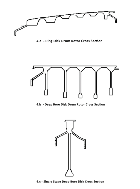
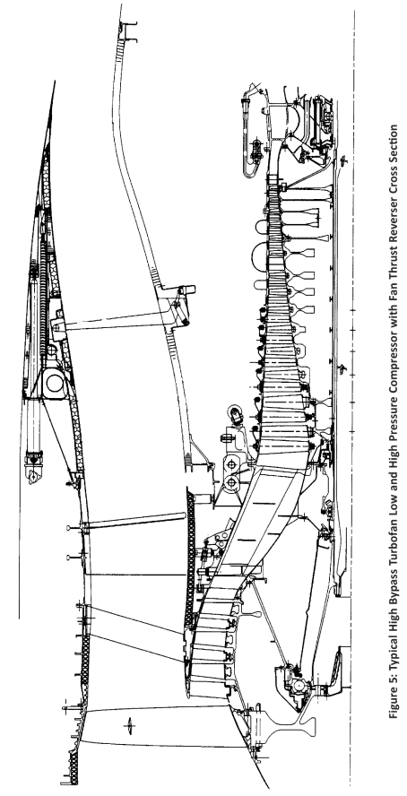
[Amdt No: 25/1]
[Amdt No: 25/24]
CS 25.934 Turbo-jet engine thrust reverser system tests
ED Decision 2003/2/RM
Thrust reversers installed on turbo-jet engines must meet the requirements of CS-E 890.
CS 25.937 Turbo-propeller-drag limiting systems
ED Decision 2003/2/RM
Turbo-propeller powered aeroplane propeller-drag limiting systems must be designed so that no single failure or malfunction of any of the systems during normal or emergency operation results in propeller drag in excess of that for which the aeroplane was designed under CS 25.367. Failure of structural elements of the drag limiting systems need not be considered if the probability of this kind of failure is extremely remote.
CS 25.939 Turbine engine operating characteristics
ED Decision 2003/2/RM
(See AMC 25.939)
(a) Turbine engine operating characteristics must be investigated in flight to determine that no adverse characteristics (such as stall, surge, or flame-out) are present, to a hazardous degree, during normal and emergency operation within the range of operation limitations of the aeroplane and of the engine. (See AMC 25.939(a).)
(b) Reserved.
(c) The turbine engine air inlet system may not, as a result of air flow distortion during normal operation, cause vibration harmful to the engine. (See AMC 25.939(c).)
AMC 25.939(a) Turbine engine operating characteristics
ED Decision 2003/2/RM
The wording ‘in flight’ should be interpreted to cover all operating conditions from engine start until shut-down.
AMC 25.939(c) Turbine engine operating characteristics
ED Decision 2003/2/RM
1 The investigation should cover the complete range, for which certification is required, of aeroplane speeds, attitudes, altitudes and engine operating conditions including reverse thrust, and of steady and transient conditions on the ground and in flight, including crosswinds, rotation, yaw and stall. Non-critical conditions of operation which need not be considered should be agreed with the Agency.
2 If the airflow conditions at the engine air intake can be affected by the operating conditions of an adjacent engine, the investigation should include an exploration of the effects of running the adjacent engine at the same and at different conditions over the whole range of engine operating conditions, including reverse thrust. An investigation of the effect of malfunctioning of an adjacent engine should also be included.
3 Compliance with the requirement may include any suitable one or combination of the following methods; as agreed with the Agency.
a. Demonstration that the variations in engine inlet airflow distortion over the range defined in 1 are within the limits established for the particular engine type.
b. An investigation of blade vibration characteristics by the method and of the scope indicated in CS-E 650 and AMC E 650 (except that Maximum Take-off rpm need not be exceeded) carried out on –
i A representative installation on the ground using test equipment where the actual conditions of operation in the aeroplane are reproduced, or
ii A representative aeroplane on the ground and in flight as appropriate to the conditions being investigated.
c. The completion of sufficient flying with representative installations prior to certification such as to demonstrate that the vibration levels are satisfactory.
d. Any other method acceptable to the Agency.
AMC 25.939 Turbine engine operating characteristics
ED Decision 2003/2/RM
FAA Advisory Circular 25.939-1 Evaluating Turbine Engine Operating Characteristics, date 19/03/86, is accepted by the Agency as providing acceptable means of compliance with CS 25.939.
CS 25.941 Inlet, engine, and exhaust compatibility
ED Decision 2007/010/R
For aeroplanes using variable inlet or exhaust system geometry, or both –
(a) The system comprised of the inlet, engine (including thrust augmentation systems, if incorporated), and exhaust must be shown to function properly under all operating conditions for which approval is sought, including all engine rotating speeds and power settings, and engine inlet and exhaust configurations;
(b) The dynamic effects of the operation of these (including consideration of probable malfunctions) upon the aerodynamic control of the aeroplane may not result in any condition that would require exceptional skill, alertness, or strength on the part of the pilot to avoid exceeding an operational or structural limitation of the aeroplane; and
(c) In showing compliance with sub-paragraph (b) of this paragraph, the pilot strength required may not exceed the limits set forth in CS 25.143(d) subject to the conditions set forth in sub-paragraphs (e) and (f) of CS 25.143.
[Amdt 25/3]
CS 25.943 Negative acceleration
ED Decision 2003/2/RM
No hazardous malfunction of an engine or any component or system associated with the powerplant may occur when the aeroplane is operated at the negative accelerations within the flight envelopes prescribed in CS 25.333. This must be shown for the greatest duration expected for the acceleration. (See also CS 25.1315.)
CS 25.945 Thrust or power augmentation system
ED Decision 2003/2/RM
(a) General. Each fluid injection system must provide a flow of fluid at the rate and pressure established for proper engine functioning under each intended operating condition. If the fluid can freeze, fluid freezing may not damage the aeroplane or adversely affect aeroplane performance.
(b) Fluid tanks. Each augmentation system fluid tank must meet the following requirements:
(1) Each tank must be able to withstand without failure the vibration, inertia, fluid, and structural loads that it may be subjected to in operation.
(2) The tanks as mounted in the aeroplane must be able to withstand without failure or leakage an internal pressure 1·5 times the maximum operating pressure.
(3) If a vent is provided, the venting must be effective under all normal flight conditions.
(4) Reserved.
(5) Each tank must have an expansion space of not less than 2% of the tank capacity. It must be impossible to fill the expansion space inadvertently with the aeroplane in the normal ground attitude.
(c) Augmentation system drains must be designed and located in accordance with CS 25.1455 if –
(1) The augmentation system fluid is subject to freezing; and
(2) The fluid may be drained in flight or during ground operation.
(d) The augmentation liquid tank capacity available for the use of each engine must be large enough to allow operation of the aeroplane under the approved procedures for the use of liquidaugmented power. The computation of liquid consumption must be based on the maximum approved rate appropriate for the desired engine output and must include the effect of temperature on engine performance as well as any other factors that might vary the amount of liquid required.