
ED Decision 2003/2/RM
(a) Each pilot compartment and its equipment must allow the minimum flight crew (established under CS 25.1523) to perform their duties without unreasonable concentration or fatigue.
(b) The primary controls listed in CS 25.779(a), excluding cables and control rods, must be located with respect to the propellers so that no member of the minimum flight crew (established under CS 25.1523), or part of the controls, lies in the region between the plane of rotation of any inboard propeller and the surface generated by a line passing through the centre of the propeller hub making an angle of 5° forward or aft of the plane of rotation of the propeller.
(c) If provision is made for a second pilot, the aeroplane must be controllable with equal safety from either pilot seat.
(d) The pilot compartment must be constructed so that, when flying in rain or snow, it will not leak in a manner that will distract the crew or harm the structure.
(e) Vibration and noise characteristics of cockpit equipment may not interfere with safe operation of the aeroplane.
CS 25.772 Pilot compartment doors
ED Decision 2003/2/RM
For an aeroplane that has a lockable door installed between the pilot compartment and the passenger compartment: -
(a) For aeroplanes with passenger seating configuration of 20 seats or more, the emergency exit configuration must be designed so that neither crewmembers nor passengers require use of the flight deck door in order to reach the emergency exits provided for them; and
(b) Means must be provided to enable flight-crew members to directly enter the passenger compartment from the pilot compartment if the cockpit door becomes jammed.
(c) There must be an emergency means to enable a crewmember to enter the pilot compartment in the event that the flight crew becomes incapacitated.
CS 25.773 Pilot compartment view
ED Decision 2016/010/R
(See AMC 25.773)
(a) Non-precipitation conditions. For non-precipitation conditions, the following apply:
(1) Each pilot compartment must be arranged to give the pilots a sufficiently extensive, clear, and undistorted view, to enable them to safely perform any manoeuvres within the operating limitations of the aeroplane, including taxiing, take-off, approach and landing.
(2) Each pilot compartment must be free of glare and reflection that could interfere with the normal duties of the minimum flight crew (established under CS 25.1523). This must be shown in day and night flight tests under non-precipitation conditions.
(b) Precipitation conditions. For precipitation conditions, the following apply:
(1) The aeroplane must have a means to maintain a clear portion of the windshield during precipitation conditions, sufficient for both pilots to have a sufficiently extensive view along the flight path in normal flight attitudes of the aeroplane. This means must be designed to function, without continuous attention on the part of the crew, in –
(i) Heavy rain at speeds up to 1·5 VSR1, with lift and drag devices retracted; and
(ii) The icing conditions specified in Appendix C and the following icing conditions specified in Appendix O, if certification for flight in icing conditions is sought (See AMC 25.773(b)(1)(ii)):
(A) For aeroplanes certificated in accordance with CS 25.1420(a)(1), the icing conditions that the aeroplane is certified to safely exit following detection.
(B) For aeroplanes certificated in accordance with CS 25.1420(a)(2), the icing conditions that the aeroplane is certified to safely operate in and the icing conditions that the aeroplane is certified to safely exit following detection.
(C) For aeroplanes certificated in accordance with CS 25.1420(a)(3), all icing conditions.
(2) No single failure of the systems used to provide the view required by sub-paragraph (b)(1) of this paragraph must cause the loss of that view by both pilots in the specified precipitation conditions.
(3) The first pilot must have a window that:
(i) is openable under the conditions prescribed in sub-paragraph (b)(1) of this paragraph when the cabin is not pressurised;
(ii) provides the view specified in (b)(1); and
(ii) gives sufficient protection from the elements against impairment of the pilot’s vision
(4) The openable window specified in sub-paragraph (b)(3) of this paragraph need not be provided if it is shown that an area of the transparent surface will remain clear sufficient for at least one pilot to land the aeroplane safely in the event of -
(i) Any system failure or combination of failures, which is not, Extremely Improbable in accordance with CS 25.1309, under the precipitation conditions specified in sub-paragraph (b)(1) of this paragraph.
(ii) An encounter with severe hail, birds, or insects. (See AMC 25.773(b)(4))
(c) Internal windshield and window fogging. The aeroplane must have a means to prevent fogging to the internal portions of the windshield and window panels over an area which would provide the visibility specified in sub-paragraph (a) of this paragraph under all internal and external ambient conditions, including precipitation conditions, in which the aeroplane is intended to be operated. (See AMC 25.773(c))
(d) Fixed markers or other guides must be installed at each pilot station to enable the pilots to position themselves in their seats for an optimum combination of outside visibility and instrument scan. If lighted markers or guides are used they must comply with the requirements specified in CS 25.1381.
[Amdt No: 25/3]
[Amdt No: 25/4]
[Amdt No: 25/16]
[Amdt No: 25/18]
AMC 25.773 Pilot compartment view
ED Decision 2015/008/R
The FAA Advisory Circular AC 25.7731: Pilot Compartment View Design Considerations (January 8, 1993), may be used to support the demonstration of compliance with CS 25.773.
[Amdt 25/4]
[Amdt 25/16]
AMC 25.773(b)(1)(ii) Pilot compartment view in icing conditions
ED Decision 2016/010/R
CS 25.773(b)(1)(ii) requires that the aeroplane have a means of maintaining a clear portion of windshield in the icing conditions defined in Appendix C and in certain Appendix O icing conditions (corresponding to the CS 25.1420 certification option selected).
The effectiveness of all cockpit windows and windshield ice and precipitation protective systems should be established within relevant icing environment. Sufficient tests, including flight test in natural or simulated Appendix C icing conditions, should be performed to validate the performance prediction done by analysis.
When thermal ice protection systems are used (e.g. electrical heating system), a thermal analysis should be conducted to substantiate the selected nominal heated capacity. Past certification experience has shown that a nominal heating capacity of 70 W/dm2 provide adequate protection in icing conditions; such value, if selected, should anyway be substantiated by the thermal analysis. The applicant should conduct dry air flight tests to verify the thermal analysis. Measurements of both the inner and outer surface temperature of the protected windshield area may be needed to verify the thermal analysis. The thermal analysis should show that the windshield surface temperature is sufficient to maintain anti-icing capability without causing structural damage to the windshield.
When anti-icing fluid systems are used, tests shall be performed to demonstrate that the fluid does not become opaque at low temperatures. The AFM should include information advising the flight crew how long it will take to deplete the amount of fluid remaining in the reservoir.
An evaluation of visibility, including distortion effects through the protected area, should be made for both day and night operations. In addition, the size and location of the protected area should be reviewed to confirm that it provides adequate visibility for the flight crew, especially during the approach and landing phases of flight.
For showing compliance with the CS-25 certification specifications relative to SLD icing conditions represented by Appendix O, the applicant may use a comparative analysis. AMC 25.1420(f) provides guidance for comparative analysis.
[Amdt 25/16]
[Amdt 25/18]
AMC 25.773(b)(4) Pilot compartment non openable windows
ED Decision 2016/010/R
Total loss of external visibility is considered catastrophic. A sufficient field of view must exist to allow the pilot to safely operate the aeroplane during all operations, including taxi.
This field of view must remain clear in all operating conditions. Precipitation conditions such as outside ice, heavy rain, severe hail, as well as encounter with birds and insects must be considered.
This AMC material applies to conventional, multiple pane window systems, i.e. those which are composed of a main windshield and separate side panels assembled with structural posts. In the event a one piece ‘uni-body wraparound’ windshield is proposed, the applicant must meet the intent of the applicable rules, even though there are no separate side windows.
1. Ice and heavy rain
— Unless system failures leading to loss of a sufficient field of view for safe operation are shown to be extremely improbable, the following provides acceptable means to show compliance with CS 25.773(b)(4):
— Each main windshield should be equipped with an independent protection system. The systems should be designed so that no malfunction or failure of one system will adversely affect the other.
— For each forward side window it should be shown that any ice accumulations (Appendix C icing conditions and any applicable Appendix O icing conditions) will not degrade visibility, or the applicant should provide individual window ice protection system capability.
— The icing accretion limits should be determined by analysis and verified by test. The extent of icing of side windows should be verified during natural or simulated icing flight tests with window ice protection systems unpowered. A limited number of test points, sufficient to validate the analysis, are required within Appendix C or Appendix O.
— For the demonstration of compliance under Appendix O icing conditions, the applicant may use a comparative analysis. AMC 25.1420(f) provides guidance for comparative analysis.
2. Hail, birds and insects
It should be shown by flight tests that exceptional pilot skill is not required to land the aeroplane using the normal aeroplane instruments and the view provided through the main or side windows having the degree of impairment to vision resulting from the encounter of severe hail, birds or insects. Appropriate test data should substantiate the estimated damage or contamination to the main or forward side windows during such an encounter.
It is unlikely that hail damage can be avoided. Rather than avoidance, the approach to ensure vision assuming hail strike has been to use damage assessment criteria contained in the ASTM International "Standard Test Method for Hail Impact Resistance of Aerospace Transparent Enclosures," ANSI/ASTM F 320-10 or equivalent. For the test set up to determine hail damage or windshield resistance to hail, reference can be made to ANSI/ASTM F 320-10, and "Global Climatic Data for Developing Military Products" MIL HDBK 310 (dated 23 June 1997).
For each impacted window, ANSI/ASTM 320-10 is used to characterize a damage pattern on a limited area of the window. For test purpose, the simulated damage patterns should be applied to the full impacted window surfaces in order to simulate in a conservative manner the visibility degradation through the windows.
The applicant should propose and substantiate the aircraft conditions when hail strike occurs. In the absence of such substantiation, the conservative assumptions will be to consider the maximum aircraft nominal speed combined with the hailstone falling speed.
When the damages are such that there is no remaining visibility through the windshield after hail encounter, or when the ice protection system is no longer operating after the hail encounter, a typical test configuration would be to block visibility out of the forward main windows for the pilot flying, and use simulated damage (if any) and ice accretions (if applicable) on the side window(s).
When conducting flight tests, adequate forward vision should be maintained for a safety pilot while providing appropriate forward view degradation for the test pilot.
Means of compliance to address birds and insects should be proposed by the applicant. The Agency is not aware of any in-service occurrence involving a total loss of visibility through the windshield after birds or insects encounter.
[Amdt 25/16]
[Amdt 25/18]
AMC 25.773(c) Internal windshield and window fogging
ED Decision 2015/008/R
In absence of pilot compartment openable windows, if the failures of the means to prevent fogging cannot be shown to be extremely improbable, the applicant should show that a sufficient field of view is maintained to allow the pilot to safely operate the aeroplane during all operations, including taxi. This should be accomplished by the following:
— The extent of fogging should be established and verified during flight tests with the means to prevent fogging inoperative,
— If it is proposed that the flight crew must take action to remove inside fogging, the effectiveness of the associated operational procedure should be demonstrated by flight test.
[Amdt 25/16]
CS 25.775 Windshields and windows
ED Decision 2016/010/R
(See AMC 25.775)
(a) Internal panes must be made of non-splintering material.
(b) Windshield panes directly in front of the pilots in the normal conduct of their duties, and the supporting structures for these panes, must withstand, without penetration, the bird impact conditions specified in CS 25.631.
(c) Unless it can be shown by analysis or tests that the probability of occurrence of a critical windshield fragmentation condition is of a low order, the aeroplane must have a means to minimise the danger to the pilots from flying windshield fragments due to bird impact. This must be shown for each transparent pane in the cockpit that –
(1) Appears in the front view of the aeroplane;
(2) Is inclined 15° or more to the longitudinal axis of the aeroplane; and
(3) Has any part of the pane located where its fragmentation will constitute a hazard to the pilots.
(d) The design of windshields and windows in pressurised aeroplanes must be based on factors peculiar to high altitude operation, including the effects of continuous and cyclic pressurisation loadings, the inherent characteristics of the material used, and the effects of temperatures and temperature differentials. The windshield and window panels must be capable of withstanding the maximum cabin pressure differential loads combined with critical aerodynamic pressure and temperature effects after any single failure in the installation or associated systems. It may be assumed that, after a single failure that is obvious to the flight crew (established under CS 25.1523), the cabin pressure differential is reduced from the maximum, in accordance with appropriate operating limitations, to allow continued safe flight of the aeroplane with a cabin pressure altitude of not more than 4572m (15 000 ft) (see AMC 25.775(d)).
(e) The windshield panels in front of the pilots must be arranged so that, assuming the loss of vision through any one panel, one or more panels remain available for use by a pilot seated at a pilot station to permit continued safe flight and landing.
[Amdt 25/18]
AMC 25.775(d) Windshields and windows
ED Decision 2021/015/R
1. PURPOSE. This AMC sets forth an acceptable means, but not the only means, of demonstrating compliance with the provisions of CS-25 pertaining to the certification requirements for windshields, windows, and mounting structure. Guidance information is provided for showing compliance with CS 25.775(d), relating to structural design of windshields and windows for aeroplanes with pressurised cabins.
2. RELATED CS PARAGRAPHS.
CS 25.775 Windshields and windows.
CS 25.365 Pressurised compartment loads.
CS 25.773(b)(3)(ii) Pilot compartment view.
CS 25.571 Damage-tolerance and fatigue evaluation of structure
3. DEFINITIONS.
a. Annealed glass. Glass that has had the internal stresses reduced to low values by heat treatment to a suitable temperature and controlled cooling.
b. Chemically toughened glass. Annealed glass immersed in a bath of molten salt resulting in an ion exchange between the salt and the glass. The composition of the salt is such that this ion exchange causes the surface of the glass to be distorted (expansion), thus putting the surface in a state of compression.
c. Creep. The change in dimension of a material under load over a period of time, not including the initial instantaneous elastic deformation. The time dependent part of strain resulting from an applied stress.
d. Cross-linking. The setting up of chemical links between molecular chains.
e. Modulus of Rupture (MOR). The maximum tensile or compressive longitudinal stress in a surface fibre of a beam loaded to failure in bending calculated from elastic theory.
f. Mounting. The structure that attaches the panel to the aircraft structure.
g. Notch sensitive. The extent to which the sensitivity of a material to fracture is increased by the presence of a surface non-homogeneity, such as a notch, a sudden change in cross section, a crack, or a scratch. Low notch sensitivity is usually associated with ductile materials, and high notch sensitivity is usually associated with brittle materials.
h. Pane/Ply. The pane/ply is a single sheet of transparent material.
i. Panel. The panel is the complete windshield or window excluding the mounting.
j. Thermally toughened glass. Annealed glass heated to its softening temperature after which the outer surfaces are rapidly cooled in a quenching medium resulting in the outer surface being put into a state of compression with the core material in tension to maintain equilibrium.
k. Toughened glass. Annealed glass placed into a state of compressive residual stress, with the internal bulk in a compensating tensile stress. Toughening may be achieved by either thermal or chemical processes.
4. BACKGROUND. Fail-safe designs have prevented depressurisations in a considerable number of windshield failure incidents. There are few transparent materials for aircraft windshield and window applications, and due to their inherent material characteristics, they are not as structurally versatile as metallic materials. Transparent materials commonly used in the construction of windshields and windows are glass, polymethyl-methacrylate (acrylic), polycarbonate, and interlayer materials. The characteristics of these materials require special engineering solutions for aircraft windshield and window panel designs.
a. Glass. In general, glass has good resistance to scratching and chemical attack, such as wiper action, solvents, and de-icing fluid. Windshield and window panel designs, however, should take into account its other unique properties, which are considerably different from metals.
(1) Glass exhibits no sharp change in physical properties when heated or cooled and has no definite melting point.
(2) Unlike metals, glass is a hard brittle material that does not exhibit plastic deformation.
(3) Glass is much stronger in compression than in tension. Fracture will occur, under any form of loading, when the induced deformation causes the tensile stress to exceed the Modulus of Rupture (MOR).
(4) The strength of glass varies with the rate of loading; the faster the rate of loading the higher the strength, as is the case for bird impact loading. In addition, glass fracture stress for a load of short duration will substantially exceed that for a sustained load.
(5) The strength of glass, whether annealed or toughened, can be reduced by edge and surface damage such as scratches, chips, and gouges. Failure is usually initiated at some point of mechanical damage on the surface. However, thermal or chemical toughening can considerably increase the fracture strength of annealed glass.
(6) Safety factors necessary on glass components. The safety factors necessary for glass components are significantly higher than for other materials used in aircraft construction because of: the loss of strength with duration of load, the variability in strength inherent in glass, and the thickness tolerances and high notch sensitivity.
(7) There are generally two types of toughened glass:
(a) Thermally toughened glass. The surface of annealed glass may be placed in a state of compression by heating the glass to its softening temperature after which the outer surfaces are rapidly cooled in a quenching medium. As mentioned, this results in the outer surface being put into a state of compression with the core material in tension to maintain equilibrium. The surface compressive layer in thermally toughened glass is approximately 18 percent of the total thickness of the glass. There are limitations on the minimum thickness of glass that can be effectively toughened by thermal processing. Very thin glass can not be effectively toughened by these methods. In general, toughening can increase the MOR of a piece of glass by approximately 3.5 to 20 times. Thermally toughened glass has significant stored energy within it. This energy is released to a certain extent when the glass fractures. Generally, the higher the stored energy the smaller particles are on fracture. Since thermal toughening leaves the glass with high compressive stresses in its surfaces, all cutting, grinding, or shaping must be done before toughening.
(b) Chemically toughened glass. Chemically toughening glass is achieved by immersion in a bath of molten salt of controlled composition. During the immersion process larger alkali ions in the salt replace smaller alkali ions in the surface of the glass. As a consequence of this unequal alkali ion exchange process, the structure of the surface of the glass is distorted by putting the surface in a state of compression similar to that of thermally toughened glass. Depending on the original glass composition and the bath processing, chemically toughened glass may have a compressive layer from 0.050 mm (0.002 inches) to over 0.50 mm (0.020 inches) regardless of the total glass thickness. The compression stress of chemically toughened glass can be made much higher than it can using thermal toughening. As the compressive layer in chemically toughened glass is much smaller than in thermally toughened glass, the stored energy within the glass does not cause the same visibility problems after failure. However, as with thermally toughened glass all cutting, grinding, and shaping must be done prior to toughening.
b. Polymethyl-methacrylate (acrylic). The acrylic materials used for aircraft transparent structural panels are unplasticised methyl-methacrylate based polymers. There are two basic forms of acrylic materials used in aircraft windshield and window panels, as-cast and biaxially stretched (stretched from a cross-linked base material).
(1) As-cast acrylic material: Forming acrylic material to a certain shape by pouring it into a mould and letting it harden without applying external pressure. Although not as notch sensitive as glass, unstretched acrylics have a notch sensitivity. This unplasticised methyl-methacrylate base polymer has good forming characteristics, optical characteristics and outdoor weathering properties.
(2) Biaxially stretched acrylic material: Stretching acrylic material aligns the polymer chains to give a laminar structure parallel to the axis of stretch, which enhances resistance to crazing, reduces crack propagation rates, and improves tensile properties. Stretching acrylic material reduces the materials formability. In addition, stretched acrylics have less notch sensitivity than unstretched acrylics.
(3) Properties. Compared with glass, these acrylics are soft and tough. In general, increasing the temperature causes a decrease in the mechanical properties of the material, increased temperature does not affect acrylic elongation and impact properties.
(4) Crazing. Both basic forms of acrylics used in aircraft transparencies are affected by crazing. Crazing is a network of fine cracks that extend over the surface of the plastic sheet (it is not confined to acrylic materials) and are often difficult to discern. These fine cracks tend to be perpendicular to the surface, very narrow, and are usually less than 0.025mm (.0010 inches) in depth. Crazing is induced by prolonged exposure to surface tensile stresses above a critical level or by exposure to organic fluids and vapours.
(a) Stress crazing may be derived from: residual stresses caused by poor forming practice; residual surface stresses induced by machining, polishing, or gouging; and prolonged loading inducing relatively high tensile stresses at a surface.
(b) Stress crazing has a severe effect on the mechanical properties of acrylics; however, the effects are reduced in stretched materials.
(c) Stress crazing affects the transparency of acrylics. Generally, stretched acrylic panels will be replaced due to loss of transparency from stress crazing before significant structural degradation occurs.
(5) Chemical resistance of acrylic materials. Typically, acrylic materials are resistant to inorganic chemicals and to some organic compounds, such as aliphatic (paraffin) hydrocarbons, hydrogenated aromatic compounds, fats, and oils.
(a) Acrylic materials are attacked and weakened by some organic compounds such as aromatic hydrocarbons (benzene), esters (generally in the form of solvents, and some de-icing fluids), ketones (acetone), and chlorinated hydrocarbons. Some hydraulic fluids are very detrimental to acrylic materials.
(b) Some detrimental compounds can induce crazing; others may dissolve the acrylic or be absorbed in the material. Crazing induced by solvent and other organic compounds has more severe effects on the mechanical properties than stress crazing. Dissolution of the acrylic and chemical absorption into the acrylic degrades the mechanical properties.
c. Polycarbonate. Polycarbonate is an amorphous thermoplastic with a glass transition temperature about 150°C, which shows large strain-to-break and high impact strength properties throughout the normal temperature range experienced by transport aircraft. Polycarbonate not only has significantly greater impact strength properties but also higher static strength properties when compared to acrylic materials.
(1) Polycarbonate exhibits very high deflections under impact conditions, which can result in higher loading into the aircraft structure, compared to glass or acrylic windshield and window panels.
(2) Polycarbonate polymer is very susceptible to degradation by the environment, due to moisture absorption and solvent stress cracking, as well as UV degradation. It is possible to prevent degradation by using good design and production practices and incorporating coatings and other forms of encapsulation. Polycarbonate also suffers from phenomena known as physical aging. This results in the change from ductile properties to brittle properties that occur when polycarbonate is exposed to temperatures between 80°C and 130°C.
(3) Polycarbonate and stretched acrylic fatigue properties are similar to metals when working (design) stresses are used for operating pressure loading design.
d. Interlayer Materials. Interlayer materials are transparent adhesive materials used to laminate glass and plastic structural plies for aircraft applications. Current choices are limited to plasticised polyvinyl butyral (incompatible with polycarbonate), polyurethane, and silicone. The most commonly used are true thermoplastics, but some polyurethanes and all silicones contain some cross-linking.
(1) Interlayer materials are considered to be non-structural because they do not directly support aircraft loads. However, glass windshields are often attached to the airframe structure through metal inserts bonded to the interlayer. For such designs the residual strength of the windshield in a condition where all glass plies have failed may be dependent upon the strength of the interlayer. In addition, the shear coupling effectiveness of the interlayer has a great influence on the stiffness of the laminate.
(2) Most interlayer materials are susceptible to moisture ingress into the laminate and are protected by compatible sealants in aircraft service.
(3) Interlayer materials, like structural plies, have a useful service life that is controlled by the surface degradation and removal of the transparency for optical reasons.
5. INTRODUCTION. The recommended methods for showing compliance with CS 25.775(d) for typical designs of windshields and windows are given in paragraph 7, Test and Analysis. Typical designs of windshields and cockpit side windows are laminated multi-plied constructions, consisting of at least two structural plies, facing plies, adhesive interlayers, protective coatings, embedded electroconductive heater films or wires, and mounting structure. Typically the structural plies are made from thermally or chemically toughened glass, or transparent polymeric materials such as polymethylmethacrylate (acrylic) and polycarbonate. These plies may be protected from abrasion, mechanical, and environmental damage by use of facing plies and/or protective coatings. The facing and structural plies are laminated together with adhesive interlayer material of poly-vinyl butyral (PVB), polyurethane, or silicone. Cabin window designs are typically multi-paned construction consisting of two structural panes (a main load bearing pane and a fail-safe pane), inner facing panes, protective coatings, and mounting structure. Generally, the two structural panes are made from polymethyl-methacrylate and separated by an air gap. However, there are some cabin window designs that have laminated structural panes. The designs with the structural panes separated by an air gap usually are such that the fail-safe pane is not loaded unless the main pane has failed.
6. GENERAL CONSIDERATIONS FOR DESIGN.
a. Items to be considered in designing the mounting for suitability over the ranges of loading and climatic conditions include but are not limited to:
(1) Deflection of the panes and mounting under pressure,
(2) Deflection of the mounting structure as a result of fuselage deflection,
(3) Differential contraction and expansion between the panes and the mounting,
(4) Deflection of the panel resulting from temperature gradient across the thickness of the panel, and
(5) Long term deformation (creep) particularly of non-metallic parts.
b. Fatigue and stress crazing should be evaluated for assemblies using polymeric structural plies. One way to reduce the occurrence of fatigue and stress crazing is by limiting the maximum working stress level over the complete panel assembly, making due allowance for expected in service deterioration resulting from weathering, minor damage, environmental attack, and the use of chemicals/cleaning fluids. This analysis should be based on:
(1) The appropriate strength of the polymer as declared by the material manufacturer under sustained loading,
(2) The panel assembly maintained at its normal working temperature as given by the windshield/window heating system, if installed, and
(3) The ambient temperature on the outside and the cabin temperature on the inside. The most adverse likely ambient temperature should be covered.
7. TESTS AND ANALYSIS. The windshield and window panels must be capable of withstanding the maximum cabin pressure differential loads combined with critical aerodynamic pressure and temperature effects for intact and single failure conditions in the installation of associated systems. When substantiation is shown by test evidence, the test apparatus should closely simulate the structural behaviour (e.g., deformation under pressure loads) of the aircraft mounting structure up to the ultimate load conditions. Analysis may be used if previous testing can validate it. The effects of the following material characteristics should be evaluated and accounted for in the design and test results: notch sensitivity, fatigue, crazing, aging effects, corrosion (degradation by fluids), temperature, UV degradation, material stability, creep, and the function and working life of the interlayer. An acceptable route for the strength substantiation of a windshield or window panel is set out below.
a. Ultimate Static Strength.
(1) Conduct a detailed structural analysis using an appropriate structural analysis method to identify the highest stressed areas of the windshield or window panel. Subsequently confirm the structural analysis by subjecting a representatively mounted and instrumented windshield or window panel to ultimate load conditions. The panel should be subjected to the most adverse combinations of pressure loading, including the maximum internal pressure, external aerodynamic pressure, temperature effects, and where appropriate, flight loads.
(2) Establish allowable strength values including allowance for material production variability, material characteristics, long term degradation, and environmental effects for each structural ply from relevant coupon or sub-component test evidence. Check the critical design case to ensure that the allowables are not exceeded by the design ultimate stresses.
(3) In lieu of 7.a.(2) above, perform a test above ultimate pressure load to account for material production variability, material characteristics, long term degradation, and environmental effects. In lieu of a rational analysis substantiating the degree of increased loading above ultimate, a factor of 2.0 may be used (ultimate is defined as 1.5 times the pressure load defined in CS 25.365(d)). A separate test fixture may be needed to preclude loading the airframe above ultimate capability.
b. Fatigue. Conventional windshield and window panel materials exhibit good intrinsic fatigue resistance properties, but the variability in fatigue life is greater than that in aircraft quality metals. Thus a conventional cyclic fatigue test, but of extended duration, may be used to cover this variability. Testing at an elevated stress level for one aircraft lifetime could also give the necessary assurance of reliability. These approaches require consideration of the endurance of the metal parts of the mounting structure. Another approach that may be used in lieu of testing is to maintain the maximum working stresses in the windshield and window panel below values at which fatigue will occur. The maximum working stress level over the complete panel assembly should be shown by supporting evidence not to exceed values consistent with the avoidance of fatigue and stress crazing, considering deterioration resulting from weathering, minor damage and scratching in service, and use of cleaner fluids, etc. Fatigue resistance of the mounting structure should be covered separately as part of the fuselage fatigue substantiation.
c. Fail-Safe. Fail-safe strength capability of the windshield and window panels should be demonstrated after any single failure in the installation or associated systems. The demonstration should account for material characteristics and variability in service material degradation, critical temperature effects, maximum cabin differential pressure, and critical external aerodynamic pressure. The requirements of CS 25.571 for the windshield or window panels may be met by showing compliance with the fail-safe criteria in this AMC. Other single failures (besides the windshield and window panels) in the installation or associated systems should also be considered. An acceptable approach for demonstrating compliance is defined by the following method:
(1) Conduct an analysis to establish the critical main pressure bearing ply.
(2) To account for the dynamic effects of a ply failure, test the representatively mounted windshield and window panel by suddenly failing the critical ply under the maximum cabin differential pressure (maximum relief valve setting) combined with the critical external aerodynamic pressure with critical temperature effects included.
(a) For windshield and window panel failures obvious to the flightcrew, the test pressure may be reduced after initial critical pane failure to account for crew action defined in the flight manual procedures. The failed windshield or window panel should withstand this reduced pressure for the period of time that would be required to complete the flight.
(b) For windshield and window panel failures, which would not be obvious to a flightcrew, the test pressure should be held for a time sufficient to account for the remaining period of flight. During the period of time when the test pressure is held, the effects of creep (if creep could occur) should be considered.
(3) Check the fail-safe stresses in all intact structural plies determined in 7c(2) to ensure that they do not exceed the material allowables developed to account for material production variability, material characteristics, long term degradation, and environmental effects.
(4) In lieu of 7c(3) above, to account for material production variability, material characteristics, long term degradation, and environmental effects, additional fail-safe testing of the windshield and window panel to loads above the fail-safe loads following the procedures defined in 7c(2) above should be conducted. In lieu of a rational analysis substantiating the degree of increased loading, a factor may be used, as shown in the table below. The factored loads should be applied after the failure of the critical ply. A separate test fixture may be needed to preclude loading the airframe above ultimate capability. The panel tested in 7c(2) may be used for this test.
(5) Load Factors (applied after the failure of the critical ply):
|
Material |
Factor |
|
Glass |
2.0 |
|
Stretched Acrylic |
2.0 |
|
Cast Acrylic |
4.0 |
|
Polycarbonate |
4.0 |
(6) Other single failures in the installation or the associated systems as they affect the transparency should also be addressed. Such failures include broken fasteners, cracked mounting components, and malfunctions in windshield heat systems.
8. OTHER FAILURE CONDITIONS THAT MAY HAVE STRUCTURAL EFFECTS
AMC 25.1309, point 10(c) ‘Considerations When Assessing Failure Condition Effects’, states that the applicant should evaluate the severity of failure conditions, considering the effects that potential or consequential effects on structural integrity may have on the aeroplane.
Therefore, the applicant should carefully consider the potential effects on the windshield structural integrity when assessing any failure condition in windshield-related systems (e.g. windshield heating systems).
Unless otherwise shown, the applicant should classify as at least hazardous a system failure condition that leads to a structural failure that could result in partial or complete loss of a windshield.
In addition, it is reminded that CS 25.365(e)(3) requires the applicant to consider the maximum compartment opening, caused by aeroplane or equipment failures (e.g. windshield failures), that is not shown to be extremely improbable.
Service experience has shown that failure or deterioration of windshield installation components (e.g. a degraded seal), combined with environmental conditions (e.g. water accumulation or moisture ingress) or with manufacturing/installation issues, may lead to failure of other components of windshield-related systems (e.g. degradation of, or damage to, the insulation of a heating-system wire). The combination of such failures may lead to a malfunction or failure of the related system, which may cause a structural failure that could result in the partial or complete loss of the windshield or the loss of transparency of the windshield.
Therefore, the applicant should pay attention to common causes of failures when installing windshields and related systems or components, and to the contribution of such common causes to cascading failures. The applicant should identify through common cause analysis appropriate design, manufacturing, installation, and maintenance precautions to mitigate the risk of any failure condition adversely affecting systems or components, which may directly or indirectly lead to a structural failure that could result in the partial or complete loss of the windshield or the loss of transparency of the windshield (refer to AMC 25.1309, Appendix 1).
[Amdt No: 25/27]
ED Decision 2013/010/R
(a) Each cockpit control must be located to provide convenient operation and to prevent confusion and inadvertent operation.
(b) The direction of movement of cockpit controls must meet the requirements of CS 25.779. Wherever practicable, the sense of motion involved in the operation of other controls must correspond to the sense of the effect of the operation upon the aeroplane or upon the part operated. Controls of a variable nature using a rotary motion must move clockwise from the off position, through an increasing range, to the full on position.
(c) The controls must be located and arranged, with respect to the pilots' seats, so that there is full and unrestricted movement of each control without interference from the cockpit structure or the clothing of the minimum flight crew (established under CS 25.1523) when any member of this flight crew from 1.58 m (5ft 2 inches) to 1·91 m (6ft 3 inches) in height, is seated with the seat belt and shoulder harness (if provided) fastened.
(d) Identical powerplant controls for each engine must be located to prevent confusion as to the engines they control.
(e) Wing-flap controls and other auxiliary lift device controls must be located on top of the pedestal, aft of the throttles, centrally or to the right of the pedestal centre line, and not less than 25 cm (10 inches) aft of the landing gear control.
(f) The landing gear control must be located forward of the throttles and must be operable by each pilot when seated with seat belt and shoulder harness (if provided) fastened.
(g) Control knobs must be shaped in accordance with CS 25.781. In addition, the knobs must be of the same colour and this colour must contrast with the colour of control knobs for other purposes and the surrounding cockpit.
(h) If a flight engineer is required as part of the minimum flight crew (established under CS 25.1523), the aeroplane must have a flight engineer station located and arranged so that the flight-crew members can perform their functions efficiently and without interfering with each other.
(i) Pitch and roll control forces and displacement sensitivity shall be compatible so that normal inputs on one control axis will not cause significant unintentional inputs on the other.
[Amdt 25/13]
AMC 25.777(c) Full and unrestricted movement of cockpit controls
ED Decision 2019/013/R9/013/R
1. General
CS 25.777(c) requires cockpit controls to be located and arranged so that full and unrestricted movement of each control can be made by the minimum flight crew. The use of the controls shall be evaluated for pilots across the range of statures required by CS 25.777(c). This evaluation should take into account foreseeable normal and failure conditions.
2. Rudder and brake controls
Particular attention should be paid to rudder and brake controls. The control movement of the rudder pedals and brake pedals should be evaluated in order to ensure that full use can be made of all the available controls in the event of an engine failure, including on take-off and including engine failure at low speeds below VMCG.
The evaluation should ensure that each member of the flight crew is always able to apply full rudder and maximum brake pressure on the same side simultaneously (e.g. full right rudder with maximum right brake pressure, and vice versa). Furthermore, the ergonomics of the design should be such that:
a) the flight crew members can, in each condition, continue to apply brake pressure on the opposite side; and
b) inadvertent brake application on the opposite side is precluded.
This evaluation should ideally be performed in a representative simulator, but it may also be performed statically in a representative cockpit.
[Amdt No: 25/23]
CS 25.779 Motion and effect of cockpit controls
ED Decision 2003/2/RM
Cockpit controls must be designed so that they operate in accordance with the following movement and actuation:
(a) Aerodynamic controls –
(1) Primary.
|
Controls |
Motion and effect |
|
Aileron |
Right (clockwise) for right wing down |
|
Elevator |
Rearward for nose up |
|
Rudder |
Right pedal forward for nose right |
(2) Secondary.
|
Controls |
Motion and effect |
|
Flaps (or auxiliary lift devices) |
Forward for wing-flaps up; rearward for flaps down |
|
Trim tabs (or equivalent) |
Rotate to produce similar rotation of the aeroplane about an axis parallel to the axis of the control |
(b) Powerplant and auxiliary controls –
(1) Powerplant.
|
Controls |
Motion and effect |
|
Power or thrust |
Forward to increase forward thrust and rearward to increase rearward thrust |
|
Propellers |
Forward to increase rpm |
(2) Auxiliary.
|
Controls |
Motion and effect |
|
Landing gear |
Down to extend |
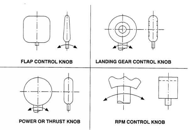
CS 25.781 Cockpit control knob shape
ED Decision 2003/2/RM
Cockpit control knobs must conform to the general shapes (but not necessarily the exact sizes or specific proportions) in the following figure:
ED Decision 2016/010/R
(See AMC 25.783)
(a) General. This paragraph applies to fuselage doors, which includes all doors, hatches, openable windows, access panels, covers, etc., on the exterior of the fuselage that do not require the use of tools to open or close. This also applies to each door or hatch through a pressure bulkhead, including any bulkhead that is specifically designed to function as a secondary bulkhead under the prescribed failure conditions of CS-25. These doors must meet the requirements of this paragraph, taking into account both pressurised and unpressurised flight, and must be designed as follows:
(1) Each door must have means to safeguard against opening in flight as a result of mechanical failure, or failure of any single structural element.
(2) Each door that could be a hazard if it unlatches must be designed so that unlatching during pressurised and unpressurised flight from the fully closed, latched, and locked condition is extremely improbable. This must be shown by safety analysis.
(3) Each element of each door operating system must be designed or, where impracticable, distinctively and permanently marked, to minimise the probability of incorrect assembly and adjustment that could result in a malfunction.
(4) All sources of power that could initiate unlocking or unlatching of any door must be automatically isolated from the latching and locking systems prior to flight and it must not be possible to restore power to the door during flight.
(5) Each removable bolt, screw, nut, pin, or other removable fastener must meet the locking requirements of CS 25.607.
(6) Certain doors, as specified by CS 25.807(h), must also meet the applicable requirements of CS 25.809 through CS 25.812 for emergency exits.
(b) Opening by persons. There must be a means to safeguard each door against opening during flight due to inadvertent action by persons. In addition, for each door that could be a hazard, design precautions must be taken to minimise the possibility for a person to open the door intentionally during flight. If these precautions include the use of auxiliary devices, those devices and their controlling systems must be designed so that:
(1) no single failure will prevent more than one exit from being opened, and
(2) failures that would prevent opening of any exit after landing must not be more probable than remote.
(c) Pressurisation prevention means. There must be a provision to prevent pressurisation of the aeroplane to an unsafe level if any door subject to pressurisation is not fully closed, latched, and locked.
(1) The provision must be designed to function after any single failure, or after any combination of failures not shown to be extremely improbable.
(2) Doors that meet the conditions described in sub-paragraph (h) of this paragraph are not required to have a dedicated pressurisation prevention means if, from every possible position of the door, it will remain open to the extent that it prevents pressurisation or safely close and latch as pressurisation takes place. This must also be shown with any single failure and malfunction except that:
(i) with failures or malfunctions in the latching mechanism, it need not latch after closing, and
(ii) with jamming as a result of mechanical failure or blocking debris, the door need not close and latch if it can be shown that the pressurisation loads on the jammed door or mechanism would not result in an unsafe condition.
(d) Latching and locking. The latching and locking mechanisms must be designed as follows:
(1) There must be a provision to latch each door.
(2) The latches and their operating mechanism must be designed so that, under all aeroplane flight and ground loading conditions, with the door latched, there is no force or torque tending to unlatch the latches. In addition, the latching system must include a means to secure the latches in the latched position. This means must be independent of the locking system.
(3) Each door subject to pressurisation, and for which the initial opening movement is not inward, must:
(i) have an individual lock for each latch;
(ii) have the lock located as close as practicable to the latch; and
(iii) be designed so that, during pressurised flight, no single failure in the locking system would prevent the locks from restraining the latches necessary to secure the door.
(4) Each door for which the initial opening movement is inward, and unlatching of the door could result in a hazard, must have a locking means to prevent the latches from becoming disengaged. The locking means must ensure sufficient latching to prevent opening of the door even with a single failure of the latching mechanism.
(5) It must not be possible to position the lock in the locked position if the latch and the latching mechanism are not in the latched position.
(6) It must not be possible to unlatch the latches with the locks in the locked position. Locks must be designed to withstand the limit loads resulting from:
(i) the maximum operator effort when the latches are operated manually;
(ii) the powered latch actuators, if installed; and
(iii) the relative motion between the latch and the structural counterpart.
(7) Each door for which unlatching would not result in a hazard is not required to have a locking mechanism meeting the requirements of sub-paragraphs (d)(3) through (d)(6) of this paragraph.
(8) A door that could result in a hazard if not closed, must have means to prevent the latches from being moved to the latched position unless it can be shown that a door that is not closed would be clearly evident before flight.
(e) Warning, caution, and advisory indications. Doors must be provided with the following indications:
(1) There must be a positive means to indicate at the door operator’s station that all required operations to close, latch, and lock the door(s) have been completed.
(2) There must be a positive means, clearly visible from each operator station for each door that could be a hazard if unlatched, to indicate if the door is not fully closed, latched, and locked.
(3) There must be a visual means on the flight deck to signal the pilots if any door is not fully closed, latched, and locked. The means must be designed such that any failure or combination of failures that would result in an erroneous closed, latched, and locked indication is remote for:
(i) each door that is subject to pressurisation and for which the initial opening movement is not inward; or
(ii) each door that could be a hazard if unlatched.
(4) There must be an aural warning to the pilots prior to or during the initial portion of take-off roll if any door is not fully closed, latched, and locked, and its opening would prevent a safe take-off and return to landing.
(f) Visual inspection provision. Each door for which unlatching could be a hazard must have a provision for direct visual inspection to determine, without ambiguity, if the door is fully closed, latched, and locked. The provision must be permanent and discernible under operational lighting conditions, or by means of a flashlight or equivalent light source.
(g) Certain maintenance doors, removable emergency exits, and access panels. Some doors not normally opened except for maintenance purposes or emergency evacuation and some access panels need not comply with certain sub-paragraphs of this paragraph as follows:
(1) Access panels that are not subject to cabin pressurisation and would not be a hazard if open during flight need not comply with sub-paragraphs (a) through (f) of this paragraph, but must have a means to prevent inadvertent opening during flight.
(2) Inward-opening removable emergency exits that are not normally removed, except for maintenance purposes or emergency evacuation, and flight deck‑openable windows need not comply with sub-paragraphs (c) and (f) of this paragraph.
(3) Maintenance doors that meet the conditions of sub-paragraph (h) of this paragraph, and for which a placard is provided limiting use to maintenance access, need not comply with sub-paragraphs (c) and (f) of this paragraph.
(h) Doors that are not a hazard. For the purposes of this paragraph, a door is considered not to be a hazard in the unlatched condition during flight, provided it can be shown to meet all of the following conditions:
(1) Doors in pressurised compartments would remain in the fully closed position if not restrained by the latches when subject to a pressure greater than 3.447 kPa (0.5 psi). Opening by persons, either inadvertently or intentionally, need not be considered in making this determination.
(2) The door would remain inside the aeroplane or remain attached to the aeroplane if it opens either in pressurised or unpressurised portions of the flight. This determination must include the consideration of inadvertent and intentional opening by persons during either pressurised or unpressurised portions of the flight.
(3) The disengagement of the latches during flight would not allow depressurisation of the cabin to an unsafe level. This safety assessment must include the physiological effects on the occupants.
(4) The open door during flight would not create aerodynamic interference that could preclude safe flight and landing.
(5) The aeroplane would meet the structural design requirements with the door open. This assessment must include the aeroelastic stability requirements of CS 25.629, as well as the strength requirements of Subpart C.
(6) The unlatching or opening of the door must not preclude safe flight and landing as a result of interaction with other systems or structures.
[Amdt 25/4]
[Amdt 25/18]
AMC 25.783 Fuselage Doors
ED Decision 2011/004/R
1. PURPOSE.
This Acceptable Means of Compliance, which is similar to the FAA Advisory Circular AC 25.783-1A describes an acceptable means for showing compliance with the requirements of CS-25 dealing with the certification of fuselage external doors and hatches.
The means of compliance described in this document is intended to provide guidance to supplement the engineering and operational judgement that must form the basis of any compliance findings relative to the structural and functional safety standards for doors and their operating systems
This document describes an acceptable means, but not the only means, for demonstrating compliance with the requirements. Terms such as “shall” and “must” are used only in the sense of ensuring applicability of this particular method of compliance when the acceptable method of compliance described in this document is used.
2. RELATED CS PARAGRAPHS.
The contents of this AMC are considered by the EASA in determining compliance of doors with the safety requirements of CS 25.783. Other related paragraphs are:
CS 25.571, “Damage-tolerance and fatigue evaluation of structure”
CS 25.607, “Fasteners”
CS 25.703, “Take-off warning system”
CS 25.809, “Emergency exit arrangement”
3. DEFINITIONS OF TERMS.
Inconsistent or inaccurate use of terms may lead to the installation of doors and hatches that do not fully meet the safety objectives of the regulations. To ensure that such installations fully comply with the regulations, the following definitions should be used when showing compliance with CS 25.783:
a. “Closed” means that the door has been placed within the door frame in such a position that the latches can be operated to the “latched” condition. “Fully closed” means that the door is placed within the door frame in the position it will occupy when the latches are in the latched condition.
b. “Door” includes all doors, hatches, openable windows, access panels, covers, etc. on the exterior of the fuselage which do not require the use of tools to open or close. This also includes each door or hatch through a pressure bulkhead including any bulkhead that is specifically designed to function as a secondary bulkhead under the prescribed failure conditions of CS-25.
c. “Door operator’s station” means the location(s) where the door closing, latching and locking operations are performed.
d. “Emergency exit” is an exit designated for use in an emergency evacuation.
e. “Exit” is a door designed to allow egress from the aeroplane.
f. “Flight” refers to that period of time from start of the take-off roll until the aeroplane comes to rest after landing.
g. “Inadvertent action by persons” means an act committed without forethought, consideration or consultation.
h. “Initial inward opening movement”. In order for a door design to be classified as having inward initial opening movement the design of its stops, guides and rollers and associated mechanism, should be such that positive pressurisation of the fuselage acting on the mean pressure plane of the fully closed door must always ensure a positive door closure force. (See AMC 25.783 Paragraph 5, (d) (4)).
i. “Initial opening movement,” refers to that door movement caused by operation of a handle or other door control mechanism, which is required to place the door in a position free of structure that would interfere with continued opening of the door.
j. “Inward” means having a directional component of movement that is inward with respect to the mean (pressure) plane of the body cut-out.
k. “Latched” means the latches are engaged with their structural counterparts and held in position by the latch operating mechanism.
l. “Latches” are movable mechanical elements that, when engaged, prevent the door from opening.
m. “Latching system” means the latch operating system and the latches.
n. “Locked” means the locks are engaged and held in position by the lock operating mechanism.
o. “Locking system” means the lock operating system and the locks.
p. “Locks” are mechanical elements in addition to the latch operating mechanism that monitor the latch positions, and when engaged, prevent latches from becoming disengaged.
q. “Stops” are fixed structural elements on the door and door frame that, when in contact with each other, limit the directions in which the door is free to move.
4. BACKGROUND.
4.1 History of incidents and accidents.
There is a history of incidents and accidents in which doors, fitted in pressurised aeroplanes, have opened during pressurised and unpressurised flight. Some of these inadvertent openings have resulted in fatal crashes. After one fatal accident that occurred in 1974, the FAA and industry representatives formed a design review team to examine the current regulatory requirements for doors to determine if those regulations were adequate to ensure safety. The team’s review and eventual recommendations led to the FAA issuing Amendment 25-54 to 14 CFR part 25 in 1980, that was adopted by the JAA in JAR-25 Change 10 in 1983, which significantly improved the safety standards for doors installed on large aeroplanes. Included as part of JAR-25 Change 10 (Amendment 25-54) was JAR 25.783, “Doors,” which provides the airworthiness standards for doors installed on large aeroplanes.
Although there have been additional minor revisions to JAR 25.783 subsequent to the issuance of Change 10 (Amendment 25-54), the safety standards for doors have remained essentially the same since 1980.
4.2 Continuing safety problems.
In spite of the improved standards brought about in 1980, there have continued to be safety problems, especially with regard to cargo doors. Cargo doors are often operated by persons having little formal instruction in their operation. Sometimes the operator is required to carry out several actions in sequence to complete the door opening and closing operations. Failure to complete all sequences during closure can have serious consequences. Service history shows that several incidents of doors opening during flight have been attributed to the failure of the operator to complete the door closure and locking sequence. Other incidents have been attributable to incorrect adjustment of the door mechanism, or failure of a vital part.
4.3 Indication to the flight crew.
Experience also has shown that, in some cases, the flight deck indication system has not been reliable. In other instances, the door indication system was verified to be indicating correctly, but the flight crew, for unknown reasons, was not alerted to the unsafe condition. A reliable indication of door status on the flight deck is particularly important on aeroplanes used in operations where the flight crew does not have an independent means readily available to verify that the doors are properly secured.
4.4 Large cargo doors as basic airframe structure.
On some aeroplanes, large cargo doors form part of the basic fuselage structure, so that, unless the door is properly closed and latched, the basic airframe structure is unable to carry the design aerodynamic and inertial loads. Large cargo doors also have the potential for creating control problems when an open door acts as an aerodynamic surface. In such cases, failure to secure the door properly could have catastrophic results, even when the aeroplane is unpressurised.
4.5 NTSB (USA) recommendations.
After two accidents occurred in 1989 due to the failure of cargo doors on transport category aeroplanes, the FAA chartered the Air Transport Association (ATA) of America to study the door design and operational issues again for the purpose of recommending improvements. The ATA concluded its study in 1991 and made recommendations to the FAA for improving the design standards of doors. Those recommendations together with additional recommendations from the National Transportation Safety Board (NTSB) were considered in the development of improved standards for doors adopted by Amendment 25-114.
5. DISCUSSION OF THE CURRENT REQUIREMENTS.
Service history has shown that to prevent doors from becoming a hazard by opening in flight, it is necessary to provide multiple layers of protection against failures, malfunctions, and human error. Paragraph 25.783 addresses these multiple layers of protection by requiring:
— a latching system;
— a locking system;
— indication systems;
— a pressure prevention means.
These features provide a high degree of tolerance to failures, malfunctions, and human error. Paragraph CS 25.783 intends that the latching system be designed so that it is inherently or specifically restrained from being back‑driven from the latches; but even so, the latches are designed to eliminate, as much as possible, all forces from the latch side that would tend to unlatch the latches. In addition to these features that prevent the latches from inadvertently opening, a separate locking system is required for doors that could be a hazard if they become unlatched. Notwithstanding these safety features, it could still be possible for the door operator to make errors in closing the door, or for mechanical failures to occur during or after closing; therefore, an indicating system is required that will signal to the flight crew if the door is not fully closed, latched, and locked. However, since it is still possible for the indication to be missed or unheeded, a separate system is required that prevents pressurisation of the aeroplane to an unsafe level if the door is not fully closed, latched, and locked.
The following material restates the requirements of CS 25.783 in italicised text and, immediately following, provides a discussion of acceptable compliance criteria.
CS 25.783(a) General Design Considerations
This paragraph applies to fuselage doors, which includes all doors, hatches, openable windows, access panels, covers, etc., on the exterior of the fuselage that do not require the use of tools to open or close. This also applies to each door or hatch through a pressure bulkhead, including any bulkhead that is specifically designed to function as a secondary bulkhead under the prescribed failure conditions of CS-25. These doors must meet the requirements of this paragraph, taking into account both pressurised and unpressurised flight, and must be designed as follows:
(a)(1) Each door must have means to safeguard against opening in flight as a result of mechanical failure, or failure of any single structural element.
Failures that should be considered when safeguarding the door against opening as a result of mechanical failure or failure of any single structural element include those caused by:
— wear;
— excessive backlash;
— excessive friction;
— jamming;
— incorrect assembly;
— incorrect adjustment;
— parts becoming loose, disconnected, or unfastened;
— parts breaking, fracturing, bending or flexing beyond the extent intended.
(a)(2) Each door that could be a hazard if it unlatches must be designed so that unlatching during pressurised and unpressurised flight from the fully closed, latched, and locked condition is extremely improbable. This must be shown by safety analysis.
All doors should incorporate features in the latching mechanism that provide a positive means to prevent the door from opening as a result of such things as:
— vibrations;
— structural loads and deflections;
— positive and negative pressure loads, positive and negative ‘g’ loads;
— aerodynamic loads etc.
The means should be effective throughout the approved operating envelope of the aeroplane including the unpressurised portions of flight.
The safety assessment required by this regulation may be a qualitative or quantitative analysis, or a combination as appropriate to the design. In evaluating a failure condition that results in total failure or inadvertent opening of the door, all contributing events should be considered, including:
— failure of the door and door supporting structure;
— flexibility in structures and linkages;
— failure of the operating system;
— erroneous signals from the door indication systems;
— likely errors in operating and maintaining the door.
(a)(3) Each element of each door operating system must be designed or, where impracticable, distinctively and permanently marked, to minimise the probability of incorrect assembly and adjustment that could result in a malfunction.
Experience has shown that the level of protection against mechanical failure can be significantly improved by careful attention to detail design. The following points should therefore be taken into account:
(a) To minimise the risk of incorrect assembly and adjustment, parts should be designed to prevent incorrect assembly if, as a result of such incorrect assembly, door functioning would be adversely affected. “Adverse effects” could be such things as preventing or impeding the opening of the door during an emergency, or reducing the capability of the door to remain closed. If such designs are impracticable and marking is used instead, the marking should remain clearly identifiable during service. In this respect, markings could be made using material such as permanent ink, provided it is resistant to typical solvents, lubricants, and other materials used in normal maintenance operations.
(b) To minimise the risk of the door operating mechanism being incorrectly adjusted in service, adjustment points that are intended for “in-service” use only should be clearly identified, and limited to a minimum number consistent with adequate adjustment capability. Any points provided solely to facilitate adjustment at the initial build and not intended for subsequent use, should be made non-adjustable after initial build, or should be highlighted in the maintenance manual as a part of the door mechanism that is not intended to be adjusted.
(a)(4) All sources of power that could initiate unlocking or unlatching of each door must be automatically isolated from the latching and locking systems prior to flight and it must not be possible to restore power to them during flight.
For doors that use electrical, hydraulic, or pneumatic power to initiate unlocking or unlatching, those power sources must be automatically isolated from the latching and locking systems before flight, and it should not be possible to restore power to them during flight. It is particularly important for doors with powered latches or locks to have all power removed that could power these systems or that could energise control circuits to these systems in the event of electrical short circuits. This does not include power to the door indicating system, auxiliary securing devices if installed, or other systems not related to door operation. Power to those systems should not be sufficient to cause unlocking or unlatching unless each failure condition that could result in energising the latching and locking systems is extremely improbable.
(a)(5) Each removable bolt, screw, nut, pin, or other removable fastener must meet the locking requirements of CS 25.607. [Fasteners]
Refer to AMC 25.607 for guidance on complying with CS 25.607.
(a)(6) Certain fuselage doors, as specified by 25.807(h), must also meet the applicable requirements of CS 25.809 through 25.812 for emergency exits.
CS 25.783(b) Opening by persons
There must be means to safeguard each door against opening during flight due to inadvertent action by persons.
The door should have inherent design features that achieve this objective. It is not considered acceptable to rely solely on cabin pressure to prevent inadvertent opening of doors during flight, because there have been instances where doors have opened during unpressurised flight, such as during landing. Therefore all doors should incorporate features to prevent the door from being opened inadvertently by persons on board.
In addition, for each door that could be a hazard, design precautions must be taken to minimise the possibility for a person to open a door intentionally during flight. If these precautions include the use of auxiliary devices, those devices and their controlling systems must be designed so that:
(1) no single failure will prevent more than one exit from being opened, and
(2) failures that would prevent opening of any exit after landing must not be more probable than remote.
The intentional opening of a door by persons on board while the aeroplane is in flight should be considered. This rule is intended to protect the aircraft and passengers but not necessarily the person who intentionally tries to open the door. Suitable design precautions should therefore be taken; however, the precautions should not compromise the ability to open an emergency exit in an emergency evacuation. The following precautions should be considered:
(a) For doors in pressurised compartments: it should not normally be possible to open the door when the compartment differential pressure is above 13.8 kPa (2 psi). The ability to open the door will depend on the door operating mechanism and the handle design, location and operating force. Operating forces in excess of 136 kg (300 pounds) should be considered sufficient to prevent the door from being opened. During approach, take-off and landing when the compartment differential pressure is lower, it is recognised that intentional opening may be possible; however, these phases are brief and all passengers are expected to be seated with seat belts fastened. Nevertheless flight experience has shown that cabin staff may cycle door handles during take-off in an attempt to ensure that the door is closed, resulting in door openings in flight. For hazardous doors CS 25.783(e)(2) intends to provide a positive means to indicate to the door operator after closure of the door on the ground, that the door is not properly closed, latched and locked. CS 25.783(e)(2) will minimise, but can not prevent the deliberate cycling of the door handle by the cabin staff during take-off.
(b) For doors that cannot meet the guidance of (a) above, and for doors in non-pressurised aeroplanes: The use of auxiliary devices (for example, a speed-activated or barometrically-activated means) to safeguard the door from opening in flight should be considered. The need for such auxiliary devices should depend upon the consequences to the aeroplane and other occupants if the door is opened in flight.
(c) Auxiliary devices installed on emergency exits: The failure of an auxiliary device should normally result in an unsecured position of the device. Failures of an auxiliary device that would prevent opening of the exit after landing should not be more probable than Remote (1x10⁻⁵/flight hour). Where auxiliary devices are controlled by a central system or other more complex systems, a single failure criterion for opening may not be sufficient. The criteria for failure of the auxiliary device to open after landing should include consideration of single failures and all failure conditions that are more probable than remote. In the assessment of single failures, no credit should be given to dormant functions.
The opening of exits on the ground should also be considered in the design, relative to the effects of differential pressure. While it is desirable and required to be able to open exits under normal residual differential pressure, opening of the exit with significant differential pressure can be a hazard to the person opening the exit. Clearly, emergency conditions may dictate that the exit be opened regardless of the differential pressure. Devices that restrict opening of the door, or affect the pressurization system, can have failure modes that create other safety concerns. However, the manufacturer should consider this issue in the design of the door and provide warnings where necessary, if it is possible to open a door under differential pressure that may be hazardous to the exit operator.
CS 25.783(c) Pressurisation prevention means
There must be a provision to prevent pressurisation of the aeroplane to an unsafe level if any door subject to pressurisation is not fully closed, latched, and locked.
(c)(1) The provision must be designed to function after any single failure, or after any combination of failures not shown to be extremely improbable.
(a) The provisions for preventing pressurisation must monitor the closed, latched and locked condition of the door. If more than one lock system is used, each lock system must be monitored. Examples of such provisions are vent panels and pressurisation inhibiting circuits. Pressurisation to an unsafe level is considered to be prevented when the pressure is kept below 3.447 kPa (1/2 psi). These systems are not intended to function to depressurise the aeroplane once the fully closed latched and locked condition is established and pressurisation is initiated.
(b) If a vent panel is used, it should be designed so that, in normal operation or with a single failure in the operating linkage, the vent panel cannot be closed until the door is latched and locked. The vent panel linkage should monitor the locked condition of each door lock system.
(c) If automatic control of the cabin pressurisation system is used as a means to prevent pressurisation, the control system should monitor each lock. Because inadvertent depressurisation at altitude can be hazardous to the occupants, this control system should be considered in showing compliance with the applicable pressurisation system reliability requirements. Normally, such systems should be automatically disconnected from the aeroplane’s pressurisation system after the aeroplane is airborne, provided no prior unsafe condition was detected.
(d) It should not be possible to override the pressurisation prevention system unless a procedure is defined in the Master Minimum Equipment List (MMEL) that confirms a fully closed, latched and locked condition. In order to prevent the override procedure from becoming routine, the override condition should not be achievable by actions solely on the flight deck and should be automatically reset at each door operational cycle.
(c)(2) Doors that meet the conditions described in sub-paragraph (h) of this paragraph are not required to have a dedicated pressurisation prevention means if, from every possible position of the door, it will remain open to the extent that it prevents pressurisation or safely close and latch as pressurisation takes place. This must also be shown with any single failure and malfunction except that:
(i) with failures or malfunctions in the latching mechanism, it need not latch after closing, and
(ii) with jamming as a result of mechanical failure or blocking debris, the door need not close and latch if it can be shown that the pressurisation loads on the jammed door or mechanism would not result in an unsafe condition.
As specified in CS 25.783(d)(7), each door for which unlatching would not result in a hazard is not required to have a locking mechanism; those doors also may not be required to have a dedicated pressurisation prevention means. However, this should be determined by demonstrating that an unsafe level of pressurisation cannot be achieved for each position that the door may take during closure, including those positions that may result from single failures or jams.
— Excluding jamming and excluding failures and malfunctions in the latching system, for every possible position of the door, it must either remain open to the extent that it prevents pressurisation, or safely close and latch as pressurisation takes place;
— With single failures of the latching system or malfunctions in the latching system the door may not necessarily be capable of latching, but it should either remain open to the extent that it prevents pressurisation, or safely move to the closed position as pressurisation takes place; and
— With jamming as a result of mechanical failure in the latching system or blocking debris, the pressurisation loads on the jammed door or mechanism may not result in damage to the door or airframe that could be detrimental to safe flight (both the immediate flight or future flights). In this regard, consideration should be given to jams or non-frangible debris that could hold the door open just enough to still allow pressurisation, and then break loose in flight after full pressurisation is reached.
CS 25.783(d) Latching and locking
The latching and locking mechanisms must be designed as follows:
(d)(1) There must be a provision to latch each door.
(a) The definitions of latches and locks are redefined in Chapter 3 [Definitions of Terms], particularly in regard to mechanical and structural elements of inward-opening plug doors. In this regard, fixed stops are not considered latches. The movable elements that hold the door in position relative to the fixed stops are considered latches. These movable elements prevent the door from opening and will support some loads in certain flight conditions, particularly when the aeroplane is unpressurised.
(b) For all doors, sub-paragraph CS 25.783(d)(2) requires that the latching system employ a securing means other than the locking system. The separate locking system may not be necessary for certain doors with an initial inward movement (see CS 25.783(d)(4)).
(d)(2) The latches and their operating mechanism must be designed so that, under all aeroplane flight and ground loading conditions, with the door latched, there is no force or torque tending to unlatch the latches. In addition, the latching system must include a means to secure the latches in the latched position. This means must be independent of the locking system.
The latches of doors for which the initial opening movement is outward are typically subject to vibrations; structural loads and deflections; positive and negative pressure loads; positive and negative ‘g’ loads; aerodynamic loads; etc. The latches of doors for which the initial opening movement is inward typically share some of these same types of loads with fixed stops. Doors for which the initial opening movement is inward tend to be resistant to opening when the aircraft is pressurised since a component of the pressure load tends to hold the door closed.
(a) Latch design. The design of the latch should be such that with the latch disconnected from its operating mechanism, the net reaction forces on the latch should not tend to unlatch the latch during both pressurised and unpressurised flight throughout the approved flight envelope. The effects of possible friction in resisting the forces on the latch should be ignored when considering reaction forces tending to unlatch the door. The effects of distortion of the latch and corresponding structural attachments should be taken into account in this determination. Any latch element for which ‘g’ loads could result in an unlatching force should be designed to minimise such forces.
(b) Latch securing means. Even though the principal back-driving forces should be eliminated by design, it is recognised that there may still be ratcheting forces that could progressively move the latches to the unlatched position. Therefore, each latch should be positively secured in the latched position by its operating mechanism, which should be effective throughout the approved flight envelope. The location of the operating system securing means will depend on the rigidity of the system and the tendency for any forces (such as ratcheting, etc.) at one latch to unlatch other latches.
(c) Over-centre features in the latching mechanism are considered to be an acceptable securing means, provided that an effective retaining feature that functions automatically to prevent back-driving is incorporated. If the design of the latch is such that it could be subject to ratcheting loads which might tend to unlatch it, the securing means should be adequate to resist such loads.
(d) Back-driving effect of switches. In those designs that use the latch to operate an electrical switch, any back-driving effect of the switch on the latch is permissible, provided that the extent of any possible movement of the switch
— is insufficient to unlatch it; and
— will not result in the latch being subjected to any other force or torque tending to unlatch it.
(e) The latch securing means must be independent of the locking means. However, the latching and locking functions may be fulfilled by a single operating means, provided that it is not possible to back-drive the locks via the latch mechanism when the door locks are engaged with the latch mechanism.
(d)(3) Each door subject to pressurisation, and for which the initial opening movement is not inward must:
(i) have an individual lock for each latch;
(ii) have the lock located as close as practicable to the latch; and
(iii) be designed so that during pressurised flight, no single failure in the locking system would prevent the locks from restraining the latches necessary to secure the door.
(a) To safeguard doors subject to pressurisation and for which the initial opening movement is not inward, each latch must have an individual lock. The lock should directly lock the latch. In this regard, the lock should be located directly at the latch to ensure that, in the event of a single failure in the latch operating mechanism, the lock would continue to restrain the latch in the latched position. Even in those cases where the lock cannot be located directly at the latch, the same objective should be achieved. In some cases, a pair of integrally-connected latches may be treated as a single latch with respect to the requirement for a lock provided that:
1) the lock reliably monitors the position of at least one of the load carrying elements of the latch, and
2) with any one latch element missing, the aeroplane can meet the full requirements of CS-25 as they apply to the unfailed aeroplane, and
3) with the pair disengaged, the aeroplane can achieve safe flight and landing, and meet the damage tolerance requirements of CS 25.571 [Damage-tolerance and fatigue evaluation of structure].
(b) In some designs more latches are provided than necessary to meet the minimum design requirements. The single failure requirement for the locking system is intended to ensure that the number and combination of latches necessary to secure the door will remain restrained by the locking mechanism. Only those latches needed to meet the minimum design requirements need to remain restrained after the single failure.
(c) In meeting this requirement, the indirect locking provided through the latch system by the locks at other latches may be considered. In this case, the locking system and the latching system between the locked latch and the unlocked latch should be designed to withstand the maximum design loads discussed in sub-paragraph d.(6) of this AMC, below, as appropriate to pressurised flight.
(d)(4) Each door for which the initial opening movement is inward, and unlatching of the door could result in a hazard, must have a locking means to prevent the latches from becoming disengaged. The locking means must ensure sufficient latching to prevent opening of the door even with a single failure of the latching mechanism.
For a door to be classified as having Initial Inward Opening Movement before opening outwards, and thus be eligible for some relief regarding the locks compared with other outward opening doors, the following conditions should be fulfilled:
a) Loads on the door resulting from positive pressure differential of the fuselage should be reacted by fixed (non moveable) structural stops on the door and fuselage doorframe.
b) The stops must be designed so that, under all 1g aeroplane level flight conditions, the door to fuselage stop interfaces produce no net force tending to move the door in the opening direction.
c) If the stops are used to provide the initial inward opening movement, the stops should be designed such that they cause the door to move inwards, typically at a minimum angle of 3° relative to the mean pressure plane, opposing any positive fuselage pressure differential:
1) until the door is in a position where it is clear of the fixed stops and is free to open, or
2) until the loads required to overcome friction between the door and fuselage stops are sufficient to prevent the door moving in an opening direction when the door is subjected to loads of +/- 0.5g, or
3) if neither of the above options are appropriate, based on justified engineering judgement and agreed with the Agency.
d) If guides or other mechanisms are used to position the door such that it can move clear of the fixed stops in an opening direction, the means used should, be designed such that it causes the door to move inwards, typically at a minimum angle of 3° relative to the mean pressure plane, opposing any positive fuselage pressure differential and be sufficiently robust to function without significant loss of effectiveness when the door is subject to a differential pressure of 13.8 kPa (2 psi):
1) until the door is in a position where it is clear of the fixed stops and is free to open, or
2) until the loads required to overcome friction are sufficient to prevent the door moving in an opening direction when the door is subjected to loads of +/- 0.5g,or
3) if neither of the above options are appropriate, based on justified engineering judgement and agreed with the Agency.
On these doors, the locking means should monitor the latch securing means, but need not directly monitor and lock each latch. Additionally, the locking means could be located such that all latches are locked by locking the latching mechanism. With any single failure in the latching mechanism, the means must still lock a sufficient number of latches to ensure that the door remains safely latched.
(d)(5) It must not be possible to position the lock in the locked position if the latch and the latching mechanism are not in the latched position.
The lock should be an effective monitor of the position of the latch such that, if any latch is unlatched, the complete locking system cannot be moved to the locked position. Although an over-centre feature may be an adequate means of securing the latching mechanism, it is not considered to be the locking means for the latches.
(d)(6) It must not be possible to unlatch the latches with the locks in the locked position. Locks must be designed to withstand the limit loads resulting from:
(i) the maximum operator effort when the latches are operated manually;
(ii) the powered latch actuators, if installed; and
(iii) the relative motion between the latch and the structural counterpart.
Although the locks are not the primary means of keeping the latches engaged, they must have sufficient strength to withstand any loads likely to be imposed during all approved modes of door operation. The operating handle loads on manually-operated doors should be based on a rational human factors evaluation. However, the application of forces on the handle in excess of 136 kg (300 pounds) need not be considered. The loads imposed by the normal powered latch actuators are generally predictable; however, loads imposed by alternate drive systems are not. For this reason the locks should have sufficient strength to react the stall forces of the latch drive system. Load-limiting devices should be installed in any alternate drive system for the latches in order to protect the latches and the locks from overload conditions. If the design of the latch is such that it could be subject to ratcheting loads which might tend to unlatch it, the locks should be adequate to resist such loads with the latch operating system disconnected from the latch.
(d)(7) Each door for which unlatching would not result in a hazard is not required to have a locking mechanism meeting the requirements of sub-paragraph (d)(3) through (d)(6) of this paragraph.
See sub-paragraph CS 25.783(h) of this AMC, below, for a description of doors for which unlatching is considered not to result in a safety hazard.
(d)(8) A door that could result in a hazard if not closed, must have means to prevent the latches from being moved to the latched position unless it can be shown that a door that is not closed would be clearly evident before flight.
For door security, it is good basic design philosophy to provide independent integrity in the closing, latching, locking and indication functions. The integrity of the closing function in particular is vulnerable to human factors and experience has shown that human error can occur resulting in an unsafe condition.
Door designs should incorporate a feature that prevents the latches from moving to the latched position if the door is not closed. The importance of such a feature is that it prevents the latched and locked functions from being completed when the door is not closed.
If the feature is provided by electronic means, the probability of failure to prevent the initiation of the latching sequence should be no greater than remote (1x10⁻⁵/flight hour).
To avoid the potential for an unsafe condition, the means provided to indicate the closed position of the door under sub-paragraph (e) should be totally independent of the feature preventing initiation of the latching sequence.
As an alternative to providing the feature described above, reliance can be placed on trained cabin crew or flight crew members to determine that certain doors are not fully closed. This alternative is applicable only to doors that are normally operated by these crew members, and where it is visually clearly evident from within the aircraft without detailed inspection under all operational lighting conditions that the door is not fully closed.
CS 25.783(e) Warning, caution and advisory indications
Doors must be provided with the following indications:
(e)(1) There must be a positive means to indicate at each door operator’s station that all required operations to close, latch, and lock the door(s) have been completed.
In order to minimise the probability of incomplete door operations, it should be possible to perform all operations for each door at one station. If there is more than one operator’s station for a single door, appropriate indications should be provided at each station. The positive means to indicate at the door operator’s station that all required operations have been completed are such things as final handle positions or indicating lights. This requirement is not intended to preclude or require a single station for multiple doors.
(e)(2) There must be a positive means, clearly visible from each operator station for each door that could be a hazard if unlatched, to indicate if the door is not fully closed, latched, and locked.
A single indication that directly monitors the door in the closed, latched and locked conditions should be provided unless the door operator has a visual indication that the door is fully closed latched and locked. This indication should be obvious to the door operator. For example, a vent door or indicator light that monitors the door locks and is located at the operator’s station may be sufficient. In case of an indicator light, it should not be less reliable than the visual means in the cockpit as required per CS 25.783(e)(3). The same sensors could be used for both indications in order to prevent any discrepancy between the indications.
(e)(3) There must be a visual means on the flight deck to signal the pilots if any door is not fully closed, latched, and locked. The means must be designed such that any failure or combination of failures that would result in an erroneous closed, latched, and locked indication is remote for:
(i) each door that is subject to pressurisation and for which the initial opening movement is not inward, or
(ii) each door that could be a hazard if unlatched.
The visual means may be a simple amber light or it may need to be a red warning light tied to the master warning system depending on the criticality of the door. The door closed, latched and locked functions must be monitored, but only one indicator is needed to signal that the door is in the closed, latched and locked condition. Indications should be reliable to ensure they remain credible. The probability of erroneous closed, latched, and locked indication should be no greater than remote (1x10⁻⁵/flight hour) for:
— each door subject to pressurisation and for which the initial opening movement is not inward; and for
— each door that could be a hazard if unlatched.
(e)(4) There must be an aural warning to the pilots prior to or during the initial portion of take-off roll if any door is not fully closed, latched, and locked and its opening would prevent a safe take-off and return to landing.
Where an unlatched door could open and prevent a safe take-off and return to landing, a more conspicuous aural warning is needed. It is intended that this system should function in a manner similar to the take-off configuration warning systems of CS 25.703 [Take-off Warning system]. The visual display for these doors may be either a red light or a display on the master warning system. Examples of doors requiring these aural warnings are:
— doors for which the structural integrity of the fuselage would be compromised if the door is not fully closed, latched and locked, or
— doors that, if open, would prevent rotation or interfere with controllability to an unacceptable level.
CS 25.783(f) Visual inspection provision
Each door for which unlatching could be a hazard, must have provisions for direct visual inspection to determine, without ambiguity, if the door is fully closed, latched, and locked. The provision must be permanent and discernible under operational lighting conditions or by means of a flashlight or equivalent light source.
A provision is necessary for direct visual inspection of the closed position of the door and the status of each of the latches and locks, because dispatch of an aeroplane may be permitted in some circumstances when a flight deck or other remote indication of an unsafe door remains after all door closing, latching and locking operations have been completed. Because the visual indication is used in these circumstances to determine whether to permit flight with a remote indication of an unsafe door, the visual indication should have a higher level of integrity than, and be independent of, the remote indication.
(a) The provisions should:
1) allow direct viewing of the position of the locking mechanism to show, without ambiguity, whether or not each latch is latched and each lock is locked. For doors which do not have a lock for each latch, direct viewing of the position of the latches and restraining mechanism may be necessary for determining that all the latches are latched. Indirect viewing, such as by optical devices or indicator flags, may be acceptable provided that there is no failure mode that could allow a false latched or locked indication.
2) preclude false indication of the status of the latches and locks as a result of changes in the viewing angle. The status should be obvious without the need for any deductive processes by the person making the assessment.
3) be of a robust design so that, following correct rigging, no unscheduled adjustment is required. Furthermore, the design should be resistant to unauthorised adjustment.
4) preclude mis-assembly that could result in a false latched and locked indication.
(b) If markings are used to assist the identification of the status of the latches and locks, such markings must include permanent physical features to ensure that the markings will remain accurately positioned.
(c) Although the visual means should be unambiguous in itself, placards and instructions may be necessary to interpret the status of the latches and locks.
(d) If optical devices or windows are used to view the latches and locks, it should be demonstrated that they provide a clear view and are not subject to fogging, obstruction from dislodged material or giving a false indication of the position of each latch and lock. Such optical devices and window materials should be resistant to scratching, crazing and any other damage from all materials and fluids commonly used in the operation and cleaning of aeroplanes.
CS 25.783(g) Certain maintenance doors, removable emergency exits, and access panels
Some doors not normally opened except for maintenance purposes or emergency evacuation and some access panels need not comply with certain sub-paragraphs of this paragraph as follows:
(1) Access panels that are not subject to cabin pressurisation and would not be a hazard if open during flight need not comply with sub-paragraphs (a) through (f) of this paragraph, but must have a means to prevent inadvertent opening during flight.
(2) Inward-opening removable emergency exits that are not normally removed, except for maintenance purposes or emergency evacuation, and flight deck‑openable windows need not comply with sub-paragraphs (c) and (f) of this paragraph.
(3) Maintenance doors that meet the conditions of sub-paragraph (h) of this paragraph, and for which a placard is provided limiting use to maintenance access, need not comply with sub-paragraphs (c) and (f) of this paragraph.
Some doors not normally opened except for maintenance purposes or emergency evacuation and some access panels are not required to comply with certain sub-paragraphs of CS 25.783 as described in CS 25.783(g). This generally pertains to access panels outside pressurised compartments whose opening is of little or no consequence to safety and doors that are not used in normal operation and so are less subject to human errors or operational damage.
CS 25.783(h) Doors that are not a hazard
For the purpose of this paragraph, a door is considered not to be a hazard in the unlatched condition during flight, provided it can be shown to meet all of the conditions as mentioned in CS 25.783(h).
CS 25.783 recognises four categories of doors:
— Doors for which the initial opening is not inward, and are presumed to be hazardous if they become unlatched.
— Doors for which the initial opening is inward, and could be a hazard if they become unlatched.
— Doors for which the initial opening is inward, and would not be a hazard if they become unlatched.
— Small access panels outside pressurised compartments for which opening is of little or no consequence to safety.
— CS 25.783(h) describes those attributes that are essential before a door in the normal (unfailed) condition can be considered not to be a hazard during flight.
6. STRUCTURAL REQUIREMENTS.
In accordance with CS 25.571, the door structure, including its mechanical features (such as hinges, stops, and latches), that can be subjected to airframe loading conditions, should be designed to be damage tolerant. In assessing the extent of damage under CS 25.571 and CS 25.783 consideration should be given to single element failures in the primary door structure, such as frames, stringers, intercostals, latches, hinges, stops and stop supports.
The skin panels on doors should be designed to be damage tolerant with a high probability of detecting any crack before the crack causes door failure or cabin decompression.
Note: This paragraph applies only to aircraft with a certification basis including CS 25.571 or equivalent requirements for damage tolerance.
[Amdt 25/4]
[Amdt 25/6]
[Amdt 25/8]
[Amdt 25/11]
CS 25.785 Seats, berths, safety belts and harnesses
ED Decision 2017/015/R
(See AMC 25.785)
(a) A seat (or berth for a non-ambulant person) must be provided for each occupant who has reached his or her second birthday.
(b) Each seat, berth, safety belt, harness, and adjacent part of the aeroplane at each station designated as occupiable during take-off and landing must be designed so that a person making proper use of these facilities will not suffer serious injury in an emergency landing as a result of the inertia forces specified in CS 25.561 and CS 25.562. However, berths intended only for the carriage of medical patients (e.g. stretchers) need not comply with the requirements of CS 25.562.
(c) Each seat or berth must be approved.
(d) Each occupant of a seat that makes more than an 18-degree angle with the vertical plane containing the aeroplane centre line must be protected from head injury by a safety belt and an energy absorbing rest that will support the arms, shoulders, head and spine, or by a safety belt and shoulder harness that will prevent the head from contacting any injurious object. Each occupant of any other seat must be protected from head injury by a safety belt and, as appropriate to the type, location, and angle of facing of each seat, by one or more of the following:
(1) A shoulder harness that will prevent the head from contacting any injurious object.
(2) The elimination of any injurious object within striking radius of the head.
(3) An energy absorbing rest that will support the arms, shoulders, head and spine.
(e) Each berth must be designed so that the forward part has a padded end board, canvas diaphragm, or equivalent means, that can withstand the static load reaction of the occupant when subjected to the forward inertia force specified in CS 25.561. Berths must be free from corners and protuberances likely to cause injury to a person occupying the berth during emergency conditions.
(f) Each seat or berth, and its supporting structure, and each safety belt or harness and its anchorage must be designed for an occupant weight of 77 kg (170 pounds), considering the maximum load factors, inertia forces, and reactions among the occupant, seat, safety belt, and harness for each relevant flight and ground load condition (including the emergency landing conditions prescribed in CS 25.561). In addition –
(1) The structural analysis and testing of the seats, berths, and their supporting structures may be determined by assuming that the critical load in the forward, sideward, downward, upward, and rearward directions (as determined from the prescribed flight, ground, and emergency landing conditions) acts separately or using selected combinations of loads if the required strength in each specified direction is substantiated. The forward load factor need not be applied to safety belts for berths.
(2) Each pilot seat must be designed for the reactions resulting from the application of the pilot forces prescribed in CS 25.395.
(3) For the determination of the strength of the local attachments of –
(i) Each seat to the structure; and
(ii) Each belt or harness to the seat or structure; a multiplication factor of 1·33 instead of the fitting factor as defined in CS 25.625 should be used for the inertia forces specified in CS 25.561. (For the lateral forces according to CS 25.561(b)(3) 1·33 times 3·0 g should be used.)
(g) Each crewmember seat at a flight-deck station must have a shoulder harness. These seats must meet the strength requirements of sub-paragraph (f) of this paragraph, except that where a seat forms part of the load path, the safety belt or shoulder harness attachments need only be proved to be not less strong than the actual strength of the seat. (See AMC 25.785(g).)
(h) Each seat located in the passenger compartment and designated for use during take-off and landing by a cabin crewmember required by the Operating Rules must be:
(1) Near a required floor level emergency exit, except that another location is acceptable if the emergency egress of passengers would be enhanced with that location. A cabin crewmember seat must be located adjacent to each Type A or B emergency exit. Other cabin crewmember seats must be evenly distributed among the required floor level emergency exits to the extent feasible.
(2) To the extent possible, without compromising proximity to a required floor level emergency exit, located to provide a direct view of the cabin area for which the cabin crewmember is responsible. (See AMC 25.785(h)(2))
(3) Positioned so that the seat will not interfere with the use of a passageway or exit when the seat is not in use.
(4) Located to minimise the probability that occupants would suffer injury by being struck by items dislodged from service areas, stowage compartments, or service equipment.
(5) Either forward or rearward facing with an energy absorbing rest that is designed to support the arms, shoulders, head and spine.
(6) Equipped with a restraint system consisting of a combined safety belt and shoulder harness unit with a single point release. There must be means to secure each restraint system when not in use to prevent interference with rapid egress in an emergency.
(i) Each safety belt must be equipped with a metal-to-metal latching device.
(j) If the seat backs do not provide a firm handhold, there must be a handgrip or rail along each aisle to enable persons to steady themselves while using the aisles in moderately rough air.
(k) Each projecting object that would injure persons seated or moving about the aeroplane in normal flight must be padded.
(l) Each forward observer’s seat required by the operating rules must be shown to be suitable for use in conducting the necessary en-route inspections.
[Amdt 25/11]
[Amdt 25/12]
[Amdt 25/13]
[Amdt 25/17]
[Amdt 25/19]
AMC 25.785 Seats, Berths, Safety Belts and Harnesses
ED Decision 2020/024/R
FAA Advisory Circular (AC) 25.785-1B, Flight Attendant Seat and Torso Restraint System Installations, dated 11.5.2010, and the relevant parts of FAA AC 25-17A Change 1, Transport Airplane Cabin Interiors Crashworthiness Handbook, dated 24.5.2016, are accepted by the Agency as providing an acceptable means of compliance with CS 25.785.
Note: ‘The relevant parts’ means ‘the parts of AC 25-17A Change 1 that address the applicable FAR/CS‑25 paragraph’.
Beds, berths, or divans convertible into a bed should be equipped with a restraint device (e.g. a belt) for use by the occupant(s) when sleeping. Beds, berths, etc. that may be occupied by more than one occupant may be equipped with a single belt.
[Amdt 25/17]
[Amdt 25/19]
[Amdt 25/26]
AMC 25.785(g) Seats, berths, safety belts and harnesses
ED Decision 2003/2/RM
Where there is a risk that a safety belt or harness might, when not in use, foul the controls or impede the crew, suitable stowage should be provided, unless it can be shown that the risk can be avoided by the application of suitable crew drills.
AMC 25.785(h)(2) Cabin Attendant Direct View
ED Decision 2017/015/R
If the total number of passenger seats approved for occupancy during taxiing, take-off, and landing is greater than the approved passenger seating configuration, the demonstration of compliance with the direct-view requirements should consider the most adverse combination of occupied seats, assuming the full passenger load on board.
[Amdt 25/19]
CS 25.787 Stowage compartments
ED Decision 2016/010/R
(See AMC 25.787)
(a) Each compartment for the stowage of cargo, baggage, carry-on articles and equipment (such as life rafts) and any other stowage compartment must be designed for its placarded maximum weight of contents and for the critical load distribution at the appropriate maximum load factors corresponding to the specified flight and ground load conditions and, where the breaking loose of the contents of such compartments could–
(1) Cause direct injury to occupants;
(2) Penetrate fuel tanks or lines or cause fire or explosion hazard by damage to adjacent systems; or
(3) Nullify any of the escape facilities provided for use after an emergency landing, to the emergency landing conditions of CS 25.561(b)(3).
If the aeroplane has a passenger-seating configuration, excluding pilot seats, of 10 seats or more, each stowage compartment in the passenger cabin, except for under seat and overhead compartments for passenger convenience, must be completely enclosed.
(b) There must be a means to prevent the contents in the compartments from becoming a hazard by shifting, under the loads specified in sub-paragraph (a) of this paragraph. (See AMC 25.787(b))
(c) If cargo compartment lamps are installed, each lamp must be installed so as to prevent contact between lamp bulb and cargo.
[Amdt 25/18]
AMC 25.787(b) Stowage compartments
ED Decision 2017/015/R
For stowage compartments in the passenger and crew compartments it must be shown by analysis and/or tests that under the load conditions as specified in CS 25.561(b)(3), the retention items such as doors, swivels, latches etc., are still performing their retention function. In the analysis and/or tests the expected wear and deterioration should be taken into account.
Stowage Compartment Latching Mechanisms:
(1) The following areas shall be considered in a special cabin interior for the purpose of designing latching mechanisms:
— Cabin crew member areas:
Cabin crew member areas are those areas in the passenger cabin where cabin crew members may be seated during taxiing, take-off, and landing (these are typically zones in proximity to floor level emergency exits, although other areas may exist).
To protect flight attendants from being struck by items dislodged from galley stowage compartments, it is common practice to install additional restraint devices (dual latching) to each stowage compartment located within a longitudinal distance equal to three rows of seats fore and aft of the cabin attendant seats. However, the following additional considerations may be used:
— A longitudinal distance of 2 metres (6.6 ft) may be used in case the ‘three rows’ criterion is difficult to assess due to widely spaced seating,
— Underseat and overhead stowage bins do not need to be considered, and
— A stowage compartment located in a closed unoccupied area during taxiing, take-off, and landing or behind a partition in the passenger cabin does not need to be considered.
— Passenger Areas:
Passengers Areas are zones in which passenger seats designed for occupancy during taxiing, take-off, and landing are installed. In such cabin areas, if the means used to prevent the contents of the compartments from becoming a hazard by shifting is a latched door, the design should take into consideration the wear and deterioration expected in service.
— Non TTOL Areas:
Non-TTOL areas are zones, separated from the remainder of the cabin by means of a door during taxiing, take-off, and landing (TTOL), in which no seat is installed (passenger or crew member) that may be occupied during taxiing, take-off, and landing, and which do not include any part of any possible egress route from the aeroplane (such areas may be for example lavatories, washrooms, bedrooms, closed galleys, etc.).
In such areas, a single latch mechanism for stowage compartments is acceptable, provided that the door separating this area from the rest of the cabin is shown to be capable of staying securely closed under the applicable emergency landing conditions of CS 25.561 with an additional inertia load, uniformly distributed on the door, equating to the highest placarded allowable single compartment contents mass inside that area. Such single latch mechanisms do not need to be designed to account for the wear and deterioration expected in service.
(2) The following is provided as a clarification of the considerations to be followed when designing latching mechanisms, as well as of the means by which wear and deterioration expected in service may be substantiated:
— Single latch:
A single latch is a latching mechanism capable of retaining a load derived from the specified maximum flight, ground and emergency landing load conditions.
— Dual latch:
A dual latch is a latching mechanism composed of two independent single latching mechanisms each of which is capable of retaining a load determined by the specified maximum flight, ground and emergency landing load conditions. It is acceptable that a single operating mechanism (e.g. handle) operates with two independent latching mechanisms at the same time.
— Latch fail indication
Latch fail indication is any means that permits clear visual confirmation that a latch is not properly engaged. In the case of a dual latching system, a single indication may serve for the two latches if it is ensured that the failure of either latch to properly engage will result in latch fail indication. All latches, whether single or dual, should include a latch fail indication.
— Wear and Deterioration
— Dual latching is a means of compliance to the wear and deterioration requirement. Where dual latches are installed there is no need to further demonstrate wear and tear.
— Consideration of wear and deterioration for single latches should be substantiated by test evidence, or analysis based on test evidence, showing that latch operation as intended by the design will be maintained following a simulation of full service life, with an appropriate scatter factor. A design life of 20 000 latch cycles may be used except if EASA finds the expected use of the aeroplane justifies more endurance substantiation. Demonstration of a 20 000 cycle design life can be accomplished by submitting the latch to a 100 000 cycle test representative of operational use, and verifying after the test that the latch is still able to operate as intended and is capable of withstanding ultimate load without failure.
(3) The above considerations regarding latching mechanisms, do not apply to compartments not accessible in flight for which a special tool is needed to gain access to (e.g. maintenance panel, access panels, etc.).
[Amdt 25/19]
ED Decision 2017/015/R
(See AMC 25.788)
(a) Showers: If a shower cubicle is installed (See AMC 25.788(a) and AMC 25.1447(c)(3)):
(1) audio and visual ‘Return to seat’ indications, readily audible and visible to a shower-cubicle occupant, and activated at the same time as the signs required by CS 25.791(b), must be provided;
(2) audio and visual indications of the need for oxygen use, readily audible and visible to a shower-cubicle occupant, and activated in the case of cabin depressurisation or deployment of the oxygen-dispensing units in the cabin, must be provided;
(3) placards must be installed to indicate that the shower cubicle must not be used for the stowage of cargo or passenger baggage;
(4) there must be means in the cubicle to steady oneself in moderately rough air; and
(5) the shower cubicle must be designed in a way to preclude anyone from being trapped inside. If a locking mechanism is installed, it must be capable of being unlocked from the inside and the outside without the aid of any tool.
(b) Large display panels: Any large display panel installed in the passenger compartment must not be a source of danger to occupants when submitted to any of the following conditions (See AMC 25.788(b)):
(1) each relevant flight and ground load conditions (including the emergency landing conditions prescribed in CS 25.561);
(2) any load to be expected in service; and
(3) a cabin depressurisation.
[Amdt 25/19]
AMC 25.788(a) Installation of Showers
ED Decision 2017/015/R
The following should be considered in the design of a shower installation:
(a) An analysis should be performed to identify possible failures leading to water leakage, and to show that appropriate mitigation features have been included in the design.
(b) The shower cubicle should be considered as a passenger compartment in terms of the need for ventilation. The applicant should justify that adequate ventilation is provided within the shower. The cabin air itself can be considered as a ‘fresh air’ source for the air supply of the shower.
(c) The shower cubicle air outflow should be directed into aeroplane areas that will not be adversely affected by the high water content of this air flow.
(d) A means to steady oneself could be either (a) firm handhold(s) specifically designed and provided for the purpose or an intrinsic design feature of the cubicle. For instance, if one or more of the cubicle wall-to-wall dimensions does not exceed 1 metre (3.3 feet), it may be assumed that an occupant can steady himself/herself by placing his/her hands on opposite wall surfaces.
(e) If electrical power outlets are installed in the room or area where the shower is present, all the following requirements should be fulfilled:
(i) the shower cubicle should be enclosed up to the ceiling;
(ii) there should be no electrical power outlet inside the shower cubicle; and
(iii) no power outlet should be placed closer than 0,6m from any point on the surface of the closed shower door.
[Amdt 25/19]
AMC 25.788(b) Large Display Panels
ED Decision 2017/015/R
1. General
This AMC does not apply to flight deck display panels. A display panel should be considered large if its diagonal is greater than 51 cm (20 in.).
Any large display panel should be shown not to be a hazard during events such as emergency landing and cabin depressurisation. It should meet the following requirements:
(a) the large display panel should withstand the differential pressures caused by a worst-case cabin depressurisation event without having any adverse effect (for instance no substances should be released through cracks or openings, no sharp edges should be created);
(b) the large display panel should be subjected to, and pass, abuse load testing (see paragraph 3 below);
(c) the installation should withstand the inertia loads outlined in CS 25.561(b)(3) without any adverse effect; and
(d) if the large display panel incorporates glass, it should be subjected to, and pass, ball impact testing (see paragraph 2 below).
With the exception of the ball impact testing, large display panels incorporating any glass element should withstand the above-defined loads with no more than minor cracks (i.e. no parts released nor the surface becoming a hazard) and without becoming dislodged from their mounts. Alternatively, the installation may still be found acceptable if some means, such as a protective cover, are provided to shield the passenger cabin from the glass monitor. The installation including its protective cover should meet all the relevant criteria identified in this AMC. Furthermore, the cover should not introduce additional hazardous characteristics of its own and should comply with all pertinent aeroplane certification requirements, e.g. flammability.
Unless it has been shown that the display panel withstands all the mechanical tests in paragraphs 1.(a) to (d) above without any damage that would result in the release of chemical substances into the cabin, documentation should be provided from medical authorities which substantiates that the type and amount of chemical substances released into the cabin in case of failure would not result in adverse health effects on cabin occupants. The specific cabin volume may be considered. Alternatively, it is acceptable to show that each installed glass screen complies with A 4(1) of Directive 2002/95/EC ‘on the restriction of the use of certain hazardous substances in electrical and electronic equipment’ (RoHS).
2. Ball Impact Testing (only for display panels containing glass)
The test procedure and pass/fail criteria of the Underwriters Laboratories standard UL 61965, Mechanical safety for cathode ray tubes, Edition 2, 27 July 2004 or former UL 1418, Standard for safety cathode ray tubes, Edition 5, 31 December 1992, or other equivalent approved method, are the basis of the ball impact strength and no-hole tests described in this paragraph.
The large display panel should be installed in a test fixture representative of the actual installation in the cabin.
2.1. Strength Test
The large display panel should be subjected to a single impact applied in accordance with the test conditions of paragraph 2.3 below. The impact energy should be 7 J, caused by a 51-mm diameter ball or, alternatively, 5.5 J, caused by a 40-mm diameter ball, as specified in paragraph 2.3.2 below.
The test is passed if the expulsion of glass within a 1-min period after the initial impact satisfies the following criteria:
(a) there is no glass particle (a single piece of glass having a mass greater than 0.025 g) between the 0.90 and 1.50-m barriers (see paragraph 2.3.1);
(b) the total mass of all pieces of glass between the 0.90 and 1.50-m barriers (see paragraph 2.3.1) does not exceed 0.1 g; and
(c) there is no glass expelled beyond the 1.50-m barrier (see paragraph 2.3.1).
2.2 No-Hole Test
The large display panel should be subjected to a single impact applied in accordance with the test conditions of paragraph 2.3 below. The impact energy should be 3.5 J, caused by a 51-mm diameter ball as specified in P 2.3.2 below.
The test is passed if the large display panel does not develop any opening that may allow a 3-mm diameter rod to enter. Cracking of the panel is permitted.
Note: If the large display panel does not develop any opening that would allow a 3-mm rod to enter when subjected to the strength test defined in paragraph 2.1 above, the no-hole test defined in this paragraph does not need to be performed.
2.3 Test Conditions
2.3.1 Test Apparatus and Setup
The centre of the large glass item should be 1.00 ± 0.05 m above the floor.
For the strength test (see paragraph 2.1 above), two barriers, each one made of material 10–20 mm thick, 250 mm high, and 2.00 m long, should be placed on the floor in front of the test item (or on both sides in case of a glass partition) at the specified location, measured horizontally from the front surface of the large glass item to the near surface of the barrier. The barriers may be less than 2.00 m long, provided that they extend to the walls of the test room. A non-skid surface such as a blanket or rug may be placed on the floor.
A solid, smooth, steel ball of the size specified in paragraph 2.3.2 below should be suspended by suitable means such as a fine wire or chain and allowed to fall freely as a pendulum and strike the large glass item with the specified impact energy. The large glass item should be placed in a way that its surface is vertical and in the same vertical plane as the suspension point of the pendulum. A single impact should be applied to any point on the surface of the large glass item at a distance of at least 25 mm from the edge of the surface.
2.3.2 Impact Objects
The 51-mm diameter steel ball used as an impact object should have a mass of approximately 0.5 kg and a minimum Scale C Rockwell Hardness of 60.
The 40-mm diameter steel ball used as an impact object should have a mass of approximately 0.23 kg and a minimum Scale C Rockwell Hardness of 60.
3. Abuse Load Tests (all large display panels)
Large display panels should withstand a 133 daN (300 lbf) static abuse load applied, in separate tests, in 5 different locations: in the centre, at the opposite corners (two separate tests), along the perimeter, at the midpoints of the short and long sides (two separate tests), or at an equivalent set of locations acceptable to EASA (see Figure 2 below).
For all the tests to be performed, the display panels should be mounted in a test fixture representative of the actual installation in the cabin.
For the above-mentioned load applications, it is acceptable to use any loading pad with a shape and dimensions that fit into a 15.24-cm (6-in.) diameter circle.
The display panels should withstand the applied loads without any adverse effect (e.g. glass elements, if present, cracking or breaking, the unit becoming dislodged from its mounts, substances released through cracks or openings, or sharp edges created).
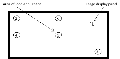 During the test, it is acceptable for the display to suffer minor failures, such as minor cracks, provided that no parts are detached and the surface does not become a hazard to occupants.
Figure 2 — Load Cases
1) centre loading;
2) corner loading;
3) opposite-corner loading;
4) short-side-midpoint perimeter loading; and
5) long-side-midpoint perimeter loading.
[Amdt 25/19]
CS 25.789 Retention of items of mass in passenger and crew compartments and galleys
ED Decision 2003/2/RM
(a) Means must be provided to prevent each item of mass (that is part of the aeroplane type design) in a passenger or crew compartment or galley from becoming a hazard by shifting under the appropriate maximum load factors corresponding to the specified flight and ground load conditions, and to the emergency landing conditions of CS 25.561(b).
(b) Each interphone restraint system must be designed so that when subjected to the load factors specified in CS 25.561(b)(3), the interphone will remain in its stowed position.
CS 25.791 Passenger information signs and placards
ED Decision 2019/013/R
(See AMC 25.791)
(a) If smoking is to be prohibited, there must be at least one placard so stating that is legible to each person seated in the cabin. If smoking is to be allowed, and if the crew compartment is separated from the passenger compartment, there must be at least one sign notifying when smoking is prohibited. Signs, which notify when smoking is prohibited, must be installed so as to be operable from either pilot’s seat and, when illuminated, must be legible under all probable conditions of cabin illumination to each person seated in the cabin.
(b) Signs that notify when seat belts should be fastened and that are installed to comply with the Operating Rules must be installed so as to be operable from either pilot’s seat and, when illuminated, must be legible under all probable conditions of cabin illumination to each person seated in the cabin.
(c) A placard must be located on or adjacent to the door of each receptacle used for the disposal of flammable waste materials to indicate that use of the receptacle for disposal of cigarettes, etc., is prohibited.
(d) Lavatories must have ‘No Smoking’ or ‘No Smoking in Lavatory’ placards conspicuously located on or adjacent to each side of the entry door.
(e) Symbols that clearly express the intent of the sign or placard may be used in lieu of letters.
[Amdt No: 25/23]
AMC 25.791 Passenger information signs and placards
ED Decision 2020/024/R
The relevant parts of FAA Advisory Circular (AC) 25-17A Change 1, Transport Airplane Cabin Interiors Crashworthiness Handbook, dated 24.5.2016, are accepted by the Agency as providing acceptable means of compliance with CS 25.791.
Note: ‘The relevant parts’ means ‘the parts of AC 25-17A Change 1 that address the applicable FAR/CS‑25 paragraph’.
[Amdt 25/11]
[Amdt 25/26]
ED Decision 2015/019/R
(See AMC to CS 25.793 and 25.810(c))
The floor surface of all areas, which are likely to become wet in service, must have slip resistant properties.
[Amdt 25/17]
AMC 25.793 and 25.810(c) Floor surfaces
ED Decision 2020/024/R
The following standard methods, using rubber and leather test devices, are acceptable (within their limitations) to conduct the testing:
— Military Specifications MIL-W-5044B (dated 24 February 1964) and MIL-W-5044C (dated 25 August 1970), titled ‘Walkway Compound, Nonslip and Walkway Matting, Nonslip’,
— DIN 51131:2014-02, titled ‘Testing of floor coverings - Determination of the anti-slip property - Method for measurement of the sliding friction coefficient’,
— ISO 8295:1995, titled ‘Plastics - Film and sheeting - Determination of coefficients of friction’,
— EN 13893:2002, titled ‘Resilient, laminate and textile floor coverings - Measurement of dynamic coefficient of friction on dry floor surfaces’,
ANSI/NFSI B101.3-2012, titled ‘Test Method for Measuring Wet DCOF of Common Hard-Surface Floor Materials’.
[Amdt 25/17]
[Amdt 25/26]
CS 25.795 Security considerations
ED Decision 2016/010/R
(see AMC 25.795)
(a) Protection of flightdeck. If a secure flightdeck door is required by operating rules, the bulkhead, door, and any other accessible boundary separating the flight crew compartment from occupied areas must be designed to:
(1) Resist forcible intrusion by unauthorised persons and be capable of withstanding impacts of 300 Joules (221.3 footpounds) as well as a 1113 Newton (250 pound) tensile load on accessible handholds, including the doorknob or handle (See AMC 25.795(a)(1)); and
(2) Resist penetration by small arms fire and fragmentation devices by meeting the following projectile definitions and projectile speeds.
(i) Demonstration Projectile #1. A 9 mm full metal jacket, round nose (FMJ RN) bullet with nominal mass of 8.0 g (124 grain) and reference velocity 436 m/s (1,430 ft/s).
(ii) Demonstration Projectile #2. A .44 Magnum, jacketed hollow point (JHP) bullet with nominal mass of 15.6 g (240 grain) and reference velocity 436 m/s (1,430 ft/s). (See AMC 25.795(a)(2))
(b) Aeroplanes with a certificated passenger seating capacity of more than 60 persons or a maximum take-off weight of over 45 500 Kg (100 000 lb) must be designed to limit the effects of an explosive or incendiary device as follows:
(1) Flight deck smoke protection. Means must be provided to limit entry of smoke, fumes, and noxious gases into the flight deck. (See AMC 25.795(b)(1))
(2) Passenger cabin smoke protection. Except for aeroplanes intended to be used solely for the transport of cargo, means must be provided to prevent passenger incapacitation in the cabin resulting from smoke, fumes, and noxious gases as represented by the initial combined volumetric concentrations of 0.59% carbon monoxide and 1.23% carbon dioxide. (See AMC 25.795(b)(2))
(3) Cargo compartment fire suppression. An extinguishing agent must be capable of suppressing a fire. All cargo-compartment fire suppression-system components must be designed to withstand the following effects, including support structure displacements or adjacent materials displacing against the distribution system:
(i) Impact or damage from a 13 mm (0.5-inch) -diameter aluminium sphere travelling at 131 m/s (430 feet per second);
(ii) A 103 kPa (15 psi) pressure load if the projected surface area of the component is greater than 0,4 square meter (4 square feet). Any single dimension greater than 1,2 meters (4 feet) may be assumed to be 1,2 meters (4 feet) in length; and
(iii) A 15 cm (6-inch) displacement, except where limited by the fuselage contour, from a single point force applied anywhere along the distribution system where relative movement between the system and its attachment can occur.
(iv) Paragraphs (b)(3)(i) through (iii) of this paragraph do not apply to components that are redundant and separated in accordance with paragraph (c)(2) of this paragraph or are installed remotely from the cargo compartment. (See AMC 25.795(b)(3))
(c) An aeroplane with a certificated passenger seating capacity of more than 60 persons or a maximum take-off weight of over 45 500 Kg (100,000 lbs) must comply with the following:
(1) Least risk bomb location. Except for aeroplanes intended to be used solely for the transport of cargo, an aeroplane must be designed with a designated location where a bomb or other explosive device could be placed to best protect integrity of the structure and flight-critical systems from damage in the case of detonation. (See AMC 25.795(c)(1))
(2) Survivability of systems.
(i) Except where impracticable, redundant aeroplane systems necessary for continued safe flight and landing must be physically separated, at a minimum, by an amount equal to a sphere of diameter
![]()
(where H0 is defined under paragraph 25.365(e)(2) and D need not exceed 1,54 meters (5.05 feet).
The sphere is applied everywhere within the fuselage-limited by the forward bulkhead and the aft bulkhead of the passenger cabin and cargo compartment beyond which only one-half the sphere is applied.
(ii) Where compliance with sub-paragraph (c)(2)(i) of this paragraph is impracticable, other design precautions must be taken to maximise the survivability of those systems. (See AMC 25.795(c)(2))
(3) Interior design to facilitate searches. Except for aeroplanes intended to be used solely for the transport of cargo, design features must be incorporated that will deter concealment or promote discovery of weapons, explosives, or other objects from a simple inspection in the following areas of the aeroplane cabin:
(i) Areas above the overhead bins must be designed to prevent objects from being hidden from view in a simple search from the aisle. Designs that prevent concealment of objects with volumes 0.33 cubic decimetre (20 cubic inches) and greater satisfy this requirement.
(ii) Toilets must be designed to prevent the passage of solid objects greater than 5 cm (2.0 inches) in diameter.
(iii) Life preservers or their storage locations must be designed so that tampering is evident. (See AMC 25.795(c)(3))
(d) Each chemical oxygen generator or its installation must be designed to be secure from deliberate manipulation by one of the following:
(1) By providing effective resistance to tampering;
(2) By providing an effective combination of resistance to tampering and active tamper-evident features;
(3) By installation in a location or manner whereby any attempt to access the generator would be immediately obvious; or
(4) By a combination of approaches specified in subparagraphs (d)(1), (d)(2) and (d)(3) of this paragraph. (See AMC 25.795(d))
[Amdt 25/9]
[Amdt 25/17]
[Amdt 25/18]
AMC 25.795 Security considerations
ED Decision 2003/2/RM
Referenced Documentation:
— FAA memorandum, Subject Information: Certification of strengthened Flight Deck Doors on Transport Category Airplanes, Original release 6 November 2001.
AMC 25.795(a)(1) Flightdeck intrusion resistance
ED Decision 2010/005/R
Referenced Documentation:
— Federal Aviation Administration Advisory Circular (AC) 25.795-1A, Flightdeck Intrusion Resistance, issue date 24 October 2008.
[Amdt 25/9]
AMC 25.795(a)(2) Flightdeck penetration resistance
ED Decision 2010/005/R
Referenced Documentation:
— Federal Aviation Administration Advisory Circular (AC) 25.795-2A, Flightdeck Penetration Resistance, issue date 24 October 2008.
— Level IIIA of the (US) National Institute of Justice, Ballistic Resistance of Personal Body Armor, NIJ Standard 0101.04, Office of Science and Technology, Washington, D.C. 20531, September 2000.
[Amdt 25/9]
AMC 25.795(b)(1) Flight deck smoke protection
ED Decision 2010/005/R
Referenced Documentation:
— Federal Aviation Administration Advisory Circular (AC) 25.795-3, Flight deck Protection (smoke and fumes), issue date 24 October 2008.
[Amdt 25/9]
AMC 25.795(b)(2) Passenger cabin smoke protection
ED Decision 2010/005/R
Referenced Documentation:
— Federal Aviation Administration Advisory Circular (AC) 25.795-4, Passenger Cabin SmokeProtection, issue date 24 October 2008.
[Amdt 25/9]
AMC 25.795(b)(3) Cargo compartment fire suppression
ED Decision 2010/005/R
Referenced Documentation:
— Federal Aviation Administration Advisory Circular (AC) 25.795-5, Cargo Compartment Fire Suppression, issue date 24 October 2008.
[Amdt 25/9]
AMC 25.795(c)(1) Least risk bomb location
ED Decision 2010/005/R
Referenced Documentation:
— Federal Aviation Administration Advisory Circular (AC) 25.795-6, Least Risk Bomb Location, issue date 24 October 2008.
[Amdt 25/9]
AMC 25.795(c)(2) Survivability of systems
ED Decision 2010/005/R
Referenced Documentation:
— Federal Aviation Administration Advisory Circular (AC) 25.795-7, Survivability of Systems, issue date 24 October 2008.
[Amdt 25/9]
AMC 25.795(c)(3) Interior design to facilitate searches
ED Decision 2010/005/R
Referenced Documentation:
— Federal Aviation Administration Advisory Circular (AC) 25.795-8, Interior design to facilitate searches, issue date 24 October 2008.
[Amdt 25/9]
AMC 25.795(d) Security of chemical oxygen generators
ED Decision 2015/019/R
1. Purpose
CS 25.795(d) requires each Chemical Oxygen Generator (COG) or its installation to be designed so that it meets one of several criteria. The means of compliance described in this AMC provides guidance to supplement the engineering and operational judgment that should form the basis of any compliance findings related to a COG installed on an aeroplane.
2. Definition of terms
For this AMC, the following definitions apply:
(a) Access: The ability to manipulate the COG with the intent of making alterations for a purpose for which the COG was not originally designed. This includes gaining access to the area surrounding the COG.
(b) Activation: Release of the firing mechanism of the COG for the purpose of initiating the chemical reaction inside.
(c) Alteration: A change in the configuration of the COG once ‘access’ has been gained for the purpose of using the COG for a function other than the one it is intended for.
(d) Chemical Oxygen Generator (COG): A device that releases oxygen that is created from a chemical reaction.
(e) Immediately obvious: Where an attempt to gain ‘access’ to the COG would be readily recognised as suspicious (prior to gaining ‘access’). This would only be in locations with ‘unrestricted access’ that are ‘observable’.
(f) Intervention: The actions crew members must take to prevent damage to the aeroplane once an alert is activated indicating that the COG is being tampered with. The time it takes to intervene when the lavatory is occupied has not been determined; however, it can be assumed that it will take several minutes to resolve the issue.
(g) Observable: A crew member is able to see if a person attempts to gain ‘access’ to a COG installation during the course of the crew member’s normal duties.
(h) Tamper-evident feature: A unique feature that provides an active and obvious contemporaneous alert to crew members that someone is trying to gain ‘access’ to the COG and immediate crew ‘intervention’ is necessary.
(i) Tamper-resistance: The level of deterrence for gaining ‘access’ to the COG.
(j) Unrestricted access: An area of the cabin passengers can enter without overcoming locks or other mechanical closure means.
3. Related Certification Specifications (CSs)
CS 25.795 Security considerations
CS 25.1301 Equipment — Function and installation
CS 25.1309 Equipment, systems, and installations
CS 25.1322 Flight crew alerting
CS 25.1450 Chemical oxygen generators
4. Compliance with CS 25.795(d)
(a) Acceptable means of determining if a COG or its installation is designed to be secure
Several criteria may be used for determining if a COG installation is secure or has a security vulnerability. COG installations with a security vulnerability must include design features to prevent potential misuse of the COG. Figure 1, Criteria for Assessing an Installation, includes assessment criteria that can be used for determining if a COG installation has a security vulnerability. Table 1 includes guidance to assist in answering the questions in Figure 1. For installations identified as having security vulnerabilities, such as those for which the answers to the assessment statements in Figure 1 result in the answer to question number 4 being yes, the design should be changed. Alternatively, the COG can be replaced with an acceptable oxygen source that is not a security threat.
Figure 1: Criteria for assessing an installation
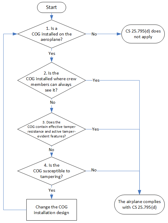
Table 1: Assessment statement analysis
|
Question number |
Notes and questions to assist with the assessment statement analysis |
|
1. |
Review the instructions for continued airworthiness. Review the drawing system. Inspect the aeroplane’s configuration. |
|
2. |
Can crew members observe the COG installation? Check the area where the COG is installed. Isolated areas such as galleys, lavatories, crew rests, enclosed occupied compartments, and lower lobe lavatory complexes are potential areas of concern and require further evaluation. Are crew members close to the COG installation during their normal duties? Are there physical barriers between the crew members and the area being evaluated? Is there significant distance between the crew members and the area being observed? How accessible is the COG? Is the COG installation surrounded by curtains? Curtained areas are also considered potential areas of concern and may require further evaluation. |
|
3. |
Are there locks on doors/access panels to prevent access? Are there tamper-resistant fasteners on panels? Are alarms or some other active alerting tamper indication method part of the installation’s design? |
|
4. |
Check if the COG can be compromised in place. Assess the vulnerability of the adjacent materials to contain the compromised device. Assess the ability of the compartment to contain the event. Check if the COG can be removed. |
(b) Installation of tamper-resistant features
Tamper-resistant design features can be used, in whole or in part, to make a COG installation secure. There are different types of tamper-resistant design features, and their functionality largely depends on the installation. The principal benefit of tamper-resistance is to delay exploitation of the COG as a weapon. However, it is not likely that an existing COG installation that can be accessed from within the lavatory could be modified with tamper-resistant design features sufficient to prevent a successful attack. This is because typical measures of tamper-resistance, such as special tools and fasteners, could likely be overcome given enough time. These measures are normally used as one of several layers of security. Thus, the reliance on such measures is only one element of the security system.
(1) A tamper-resistant installation employs multiple elements, which may include:
(i) the COG’s location;
(ii) the method of mounting;
(iii) physical protection (through shielding or mechanical isolation of key components); and
(iv) internal design.
(2) Eliminating access to the COG is the most straightforward way to make the COG tamper-resistant. Typically, this can be done by placing the COG in a location where significant disassembly of the cabin interior would be required to gain access. For example, the COG for a lavatory could be located so that the entire lavatory module would have to be removed to access the COG. However, the installer should also consider the ramifications on maintenance when this approach is used.
(c) Installation of tamper-evident features
(1) For COGs that can be accessed from isolated compartments, such as lavatories, some form of active tamper-evidence (for example, an alert) would be needed in addition to the installation of tamper-resistant features. This is necessary so that the time to intervene and stop the attack is less than the time required to carry out the attack. In this case, passive tamper-evident features, such as a tamper-evident seal, are not effective because they provide an after-the-fact notification of tampering. The effectiveness of a tamper-evident system depends on intervention; it cannot be assumed that the alarm by itself would inhibit the attack.
(2) Once an alert is activated indicating that the COG is being tampered with, actions by crew members and other available, authorised responders are necessary to prevent catastrophic damage to the aeroplane. Therefore, there is a critical relationship between the tamper-evidence system and the training and capability of the crew to respond. To be most effective, crew training should be accomplished prior to the alarm feature being deployed into the fleet. The time needed to successfully respond to the alarm may be several minutes and depends on several factors. The time available to respond to a threat and intervention times are functions of not only the design features but also of many complex and human factor-dependent variables that are difficult to define. These variables include but are not limited to the individual capabilities and numbers of flight attendants/authorised responders relative to the terrorists/accomplices, as well as the extensiveness of the training received.
(3) In order to be effective, the alerting system must itself be resistant to tampering. Otherwise, the entire concept of using the early notification to crew could be nullified and the COG accessed without impediment.
(d) System safety considerations
The applicant should consult AMC 25.1309 for guidance on compliance with CS 25.1309.
(e) Hazard classification. Failure of tamper-resistant or tamper-evident features should be considered major.
(f) System performance when installed
A tamper-evidence system installed for compliance with CS 25.795(d) is intended to notify crew members that someone is trying to gain access to a COG. The system should provide aural and visual warnings to immediately notify crew members so that they can provide direct response in a timely manner. For example, visual indication should be provided so that crew members can identify which COG location is being tampered with while performing their normal duties. Aural alerts should be distinct from other alerts and clearly audible to the crew members expected to respond to the alert. If an alert is provided to the flight crew, the alert should be presented in accordance with CS 25.1322.
5. Areas that are immediately obvious
For COG installations located where any attempt to access would be immediately obvious, additional safety measures are not required. Immediately obvious areas include the main passenger cabin and other areas where occupants are always present. While some measure of tamper-resistance is encouraged for these locations, none is required to meet CS 25.795(d). Private compartments (such as a lavatory) or visually divided sections of larger cabin areas are assessed independently. The ‘immediately obvious’ criterion applies to the specific location of each COG installation, not simply the general area in which it is located. In addition, the installation should be evaluated under all conditions that may exist during a flight. So, for example, if tampering would be immediately obvious except when a curtain is pulled to provide privacy, the installation should be evaluated based on the curtain being arranged in a way that most conceals the installation. As with tamper-evident designs, crews should be made aware that tampering with any COG is a safety risk, and any necessary information should be incorporated into the training programmes.
[Amdt 25/17]