
CS 25.1301 Function and installation
ED Decision 2008/006/R
(See AMC 25.1301)
(a) Each item of installed equipment must –
(1) Be of a kind and design appropriate to its intended function;
(2) Be labelled as to its identification, function, or operating limitations, or any applicable combination of these factors. (See AMC 25.1301(a)(2).)
(3) Be installed according to limitations specified for that equipment.
(b) Electrical wiring interconnection systems must meet the requirements of subpart H of this CS-25.
[Amdt 25/2]
[Amdt 25/5]
AMC 25.1301(a)(2) Function and installation
ED Decision 2008/006/R
When pipelines are marked for the purpose of distinguishing their functions, the markings should be such that the risk of confusion by maintenance or servicing personnel will be minimised. Distinction by means of colour markings alone is not acceptable. The use of alphabetic or numerical symbols will be acceptable if recognition depends upon reference to a master key and any relation between symbol and function is carefully avoided. Specification ISO.12 version 2ED 1987 gives acceptable graphical markings.
[Amdt 25/5]
CS 25.1302 Installed systems and equipment for use by the flight crew
ED Decision 2007/010/R
(See AMC 25.1302.)
This paragraph applies to installed equipment intended for flight-crew members’ use in the operation of the aeroplane from their normally seated positions on the flight deck. This installed equipment must be shown, individually and in combination with other such equipment, to be designed so that qualified flight-crew members trained in its use can safely perform their tasks associated with its intended function by meeting the following requirements:
(a) Flight deck controls must be installed to allow accomplishment of these tasks and information necessary to accomplish these tasks must be provided.
(b) Flight deck controls and information intended for flight crew use must:
(1) Be presented in a clear and unambiguous form, at resolution and precision appropriate to the task.
(2) Be accessible and usable by the flight crew in a manner consistent with the urgency, frequency, and duration of their tasks, and
(3) Enable flight crew awareness, if awareness is required for safe operation, of the effects on the aeroplane or systems resulting from flight crew actions.
(c) Operationally-relevant behaviour of the installed equipment must be:
(1) Predictable and unambiguous, and
(2) Designed to enable the flight crew to intervene in a manner appropriate to the task.
(d) To the extent practicable, installed equipment must enable the flight crew to manage errors resulting from the kinds of flight crew interactions with the equipment that can be reasonably expected in service, assuming the flight crew is acting in good faith. This sub-paragraph (d) does not apply to skill-related errors associated with manual control of the aeroplane.
[Amdt 25/3]
AMC 25.1302 Installed Systems and Equipment for Use by the Flight Crew
ED Decision 2007/010/R
Table of content
1. Purpose
2. Background
3. Scope and Assumptions
4. Certification Planning
5. Design Considerations and Guidance
6. Means of Compliance
Appendix 1: Related Regulatory Material
Appendix 2: Definitions and Acronyms
1. PURPOSE
This Acceptable Means of Compliance (AMC) provides guidance material for demonstrating compliance with the requirements of CS 25.1302 and several other paragraphs in CS-25 that relate to the installed equipment used by the flight crew in the operation of an aeroplane. In particular, this AMC addresses the design and approval of installed equipment intended for the use of flight-crew members from their normally seated positions on the flight deck. This AMC also provides recommendations for the design and evaluation of controls, displays, system behaviour, and system integration, as well as design guidance for error management.
Applicants should use Paragraphs 4, 5 and 6 of this AMC together to constitute an acceptable means of compliance. Paragraph 4 “Certification Planning”, describes the activities and communication between the applicant and the Agency for certification planning. Paragraph 5 “Design Considerations and Guidance”, is organised in accordance with the sub-paragraphs of CS 25.1302 and identifies HF related design issues that should be addressed to show compliance with CS 25.1302 and other relevant rules. Paragraph 6 “Means of Compliance” describes general means of compliance and how they may be used.
2. BACKGROUND
Flight crews make a positive contribution to the safety of the air transportation system because of their ability to assess continuously changing conditions and situations, analyse potential actions, and make reasoned decisions. However, even well trained, qualified, healthy, alert flight-crew members make errors. Some of these errors may be influenced by the design of the systems and their flight crew interfaces, even with those that are carefully designed. Most of these errors have no significant safety effects, or are detected and/or mitigated in the normal course of events,. Still, accident analyses have identified flight crew performance and error as significant factors in a majority of accidents involving transport category aeroplanes.
Accidents most often result from a sequence or combination of errors and safety related events (e.g., equipment failure and weather conditions). Analyses show that the design of the flight deck and other systems can influence flight crew task performance and the occurrence and effects of some flight crew errors.
Some current regulatory requirements mean to improve aviation safety by requiring that the flight deck and its equipment be designed with certain capabilities and characteristics. Approval of flight deck systems with respect to design-related flight crew error has typically been addressed by referring to system specific or general applicability requirements, such as CS 25.1301(a), CS 25.771(a), and CS 25.1523. However, little or no guidance exists to show how the applicant may address potential crew limitations and errors. That is why CS 25.1302 and this guidance material have been developed.
Often, showing compliance with design requirements that relate to human abilities and limitations is subject to a great deal of interpretation. Findings may vary depending on the novelty, complexity, or degree of integration related to system design. The EASA considers that guidance describing a structured approach to selecting and developing acceptable means of compliance is useful in aiding standardised certification practices.
This AMC provides guidance for showing compliance with CS 25.1302 and guidance related to several other requirements associated with installed equipment the flight crew uses in operating the aeroplane. Table 1 below contains a list of requirements related to flight deck design and flight crew interfaces for which this AMC provides guidance. Note that this AMC does not provide a comprehensive means of compliance for any of the requirements beyond CS 25.1302.
This material applies to flight crew interfaces and system behaviour for installed systems and equipment used by the flight crew on the flight deck while operating the aeroplane in normal and non-normal conditions. It applies to those aeroplane and equipment design considerations within the scope of CS-25 for type certificate and supplemental type certificate (STC) projects. It does not apply to flight crew training, qualification, or licensing requirements. Similarly, it does not apply to flight crew procedures, except as required within CS-25.
In showing compliance to the requirements referenced by this AMC, the applicant may assume a qualified flight crew trained in the use of the installed equipment. This means a flight crew that is allowed to fly the aeroplane by meeting the requirements in the operating rules for the relevant Authority.
Paragraph 3 - Table 1: Requirements relevant to this AMC.
|
CS-25 BOOK 1 Requirements |
General topic |
Referenced material in this AMC |
|
CS 25.771(a) |
Unreasonable concentration or fatigue |
Error, 5.6. Integration, 5.7. Controls, 5.3. System Behaviour, 5.5. |
|
CS 25.771(c) |
Controllable from either pilot seat |
Controls, 5.3. Integration, 5.7. |
|
CS 25.773 |
Pilot compartment view |
Integration, 5.7. |
|
CS 25.777(a) |
Location of cockpit controls. |
Controls, 5.3. Integration, 5.7. |
|
CS 25.777(b) |
Direction of movement of cockpit controls |
Controls, 5.3. Integration, 5.7. |
|
CS 25.777(c) |
Full and unrestricted movement of controls |
Controls, 5.3. Integration, 5.7. |
|
CS 25.1301(a) |
Intended function of installed systems |
Error, 5.6. Integration, 5.7. Controls, 5.3. Presentation of Information, 5.4. System Behaviour, 5.5. |
|
CS 25.1302 |
Flight crew error |
Error, 5.6. Integration, 5.7. Controls, 5.3. Presentation of Information, 5.4. System Behaviour, 5.5. |
|
CS 25.1303 |
Flight and navigation instruments |
Integration, 5.7. |
|
CS 25.1309(a) |
Intended function of required equipment under all operating conditions |
Controls, 5.3. Integration, 5.7. |
|
CS 25.1309(c) |
Unsafe system operating conditions and minimising crew errors which could create additional hazards |
Presentation of information, 5.4. Errors, 5.6. |
|
CS 25.1321 |
Visibility of instruments |
Integration, 5.7. |
|
CS 25.1322 |
Warning caution and advisory lights |
Integration, 5.7. |
|
CS 25.1329 |
Autopilot, flight director and autothrust |
System Behaviour, 5.5. |
|
CS 25.1523 |
Minimum flight crew |
Controls, 5.3. Integration, 5.7. |
|
CS 25.1543(b) |
Visibility of instrument markings |
Presentation of Information, 5.4. |
|
CS 25.1555 (a) |
Control markings |
Controls, 5.3. |
|
CS 25 Appendix D |
Criteria for determining minimum flight crew |
Integration, 5.7. |
CS 25.1302 is a general applicability requirement. Other CS-25 requirements exist for specific equipment and systems. Where guidance in other AMCs is provided for specific equipment and systems, that guidance is assumed to have precedence if a conflict exists with guidance provided here. Appendix 1 of this AMC lists references to other related regulatory material and documents.
This paragraph describes applicant activities, communication between the applicant and the Agency, and the documentation necessary for finding compliance in accordance with this AMC. Requirements for type certification related to complying with CS-25 may be found in Part 21.
Applicants can gain significant advantages by involving the Agency in the earliest possible phases of application and design. This will enable timely agreements on potential design related human factors issues to be reached and thereby reduce the applicant’s risk of investing in design features that may not be acceptable to the Agency.
Certain activities that typically take place during development of a new product or a new flight deck system or function, occur before official certification data is submitted to demonstrate compliance with the requirements. The applicant may choose to discuss or share these activities with the Agency on an information-only basis. Where appropriate, the Agency may wish to participate in assessments the applicant is performing with mock-ups, prototypes, and simulators.
When the Agency agrees, as part of the certification planning process, that a specific evaluation, analysis, or assessment of a human factors issue will become part of the demonstration that the design is in compliance with requirements, that evaluation, analysis, or assessment is given “certification credit”.
Figure 1 illustrates the interaction between paragraph 4, 5 and 6 of this AMC. These paragraphs are used simultaneously during the certification process. Paragraph 4 details applicant activities and communication between the applicant and the Agency. Paragraph 5 provides means of compliance on specific topics. Paragraphs 5.2, 5.6 and 5.7 assist the applicant in determining inputs required for the scoping discussions outlined in paragraph 4.1. Paragraphs 5.3 through 5.5 provide guidance in determining the list of applicable requirements for discussion, outlined in paragraph 4.2. Paragraph 6 provides a list of acceptable general means of compliance used to guide the discussions for paragraph 4.3. Paragraph 4.4 lists items that may be documented as a result of the above discussions.
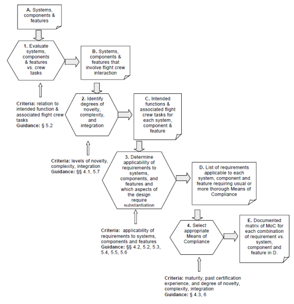
Paragraph 4 - Fig. 1: Methodical approach to planning certification for design related Human performance issues
4.1 Scope of the flight deck certification programme
This paragraph provides means of establishing the scope of the certification programme.
In a process internal to the applicant, the applicant should consider the flight deck controls, information and system behaviour that involve flight crew interaction. The applicant should relate the intended functions of the system(s), components and features to the flight crew tasks. The objective is to improve understanding about how flight crew tasks might be changed or modified as a result of introducing the proposed system(s), components and features. Paragraph 5.2, Intended Function and Associated Flight Crew Tasks, provides guidance.
The certification programme may be impacted by the level of integration, complexity and novelty of the design features, each of which is described in the sub-paragraphs that follow. Taking these features into account, the applicant should reach an agreement with the Agency on the scope of flight deck controls, information and system behaviour that will require extra scrutiny during the certification process. Applicants should be aware that the impact of a novel feature might also be affected by its complexity and the extent of its integration with other elements of the flight deck. A novel but simple feature will likely require less rigorous scrutiny than one that is both novel and complex.
a) Integration
In this document, the term “level of systems integration”, refers to the extent to which there are interactions or dependencies between systems affecting the flight crew’s operation of the aeroplane. The applicant should describe such integration among systems, because it may affect means of compliance. Paragraph 5.7 also refers to integration. In the context of that paragraph, integration defines how specific systems are integrated into the flight deck and how the level of integration may affect the means of compliance.
b) Complexity
Complexity of the system design from the flight crew’s perspective is an important factor that may also affect means of compliance in this process. Complexity has multiple dimensions. The number of information elements the flight crew has to use (the number of pieces of information on a display, for instance) may be an indication of complexity. The level of system integration may be a measure of complexity of the system from the flight crew’s perspective. Design of controls can also be complex. An example would be a knob with multiple control modes. Paragraph 5 addresses several aspects of complexity.
c) Novelty
The applicant should identify the degree of design novelty based on the following factors:
— Are new technologies introduced that operate in new ways for either established or new flight deck designs?
— Are unusual or additional operational procedures needed as a result of the introduction of new technologies?
— Does the design introduce a new way for the flight crew to interact with systems using either conventional or innovative technology?
— Does the design introduce new uses for existing systems that change the flight crew’s tasks or responsibilities?
Based on the above criteria, the applicant should characterise features by their novelty. More novel features may require extra scrutiny during certification. Less novel features must still be shown to be compliant with requirements, but will usually follow a typical certification process that may be less rigorous than the process described below.
The applicant should identify design requirements applicable to each of the systems, components, and features for which means of demonstrating compliance must be selected. This can be accomplished in part by identifying design characteristics that can adversely affect flight crew performance, or that pertain to avoidance and management of flight crew errors.
Specific design considerations for requirements involving human performance are discussed in Paragraph 5. The applicability of each design consideration in Paragraph 5 will depend on the design characteristics identified in paragraph 4.1.
4.3 Select appropriate means of compliance
After identifying what should be shown in order to demonstrate compliance, the applicant should review paragraph 6.1 for guidance on selecting the means, or multiple means of compliance, appropriate to the design. In general, it is expected that the level of scrutiny or rigour represented by the means of compliance should increase with higher levels of novelty, complexity and integration of the design.
Paragraph 6 identifies general means of compliance that have been used on many certification programmes and discusses their selection, appropriate uses, and limitations. The applicant may propose other general means of compliance, subject to approval by the Agency.
Once the human performance issues have been identified and means of compliance have been selected and proposed to the Agency, the Agency may agree, as part of the certification planning process, that a specific evaluation, analysis or assessment of a human factors issue will become part of the demonstration that the design is in compliance with requirements. Certification credit can be granted when data is transmitted to and accepted by the Agency using standard certification procedures. This data will be a part of the final record of how the applicant has complied with the requirements.
The output of this step will consist of the means that will be used to show compliance to the requirements.
4.4 Certification plan
The applicant should document the certification process, outputs and agreements described in the previous paragraphs. This may be done in a separate plan or incorporated into a higher level certification plan. The following is a summary of what may be contained in the document:
— The new aeroplane, system, control, information or feature(s)
— The design feature(s) being evaluated and whether or not the feature(s) is(are) new or novel
— The integration or complexity of the new feature(s)
— Flight crew tasks that are affected or any new tasks that are introduced
— Any new flight crew procedures
— Specific requirements that must be complied with
— The means (one or several) that will be used to show compliance
— The method for transferring data to the Agency
5. DESIGN CONSIDERATIONS AND GUIDANCE
This paragraph contains a discussion of CS 25.1302 and guidance on complying with it and other requirements.
The applicant should first complete the following steps.
— Identify systems, components, and features of a new design that are potentially affected by the requirements.
— Assess degrees of novelty, complexity, and level of integration using the initial process steps in paragraph 4.
Once these steps have been completed, use the contents of this paragraph to identify what should be shown to demonstrate compliance.
To comply with the requirements of CS-25, the design of flight deck systems should appropriately address foreseeable capabilities and limitations of the flight crew. To aid the applicant in complying with this overall objective, this paragraph has been divided into sub-paragraphs. They provide guidance on the following topics:
— Applicability and Explanatory material to CS 25.1302 (See paragraph 5.1),
— Intended function and associated flight crew tasks(See paragraph 5.2),
— Controls (See paragraph 5.3),
— Presentation of information(See paragraph 5.4),
— System behaviour (See paragraph 5.5),
— Flight crew error management(See paragraph 5.6),
— Integration (See paragraph 5.7),
Each sub-paragraph discusses what the applicant should show to establish compliance with applicable requirements. We are not describing here what might otherwise be referred to as industry “best practices.” The guidance presented here is the airworthiness standard for use in compliance. Obviously, not all criteria can or should be met by all systems. Because the nature of the guidance in this AMC is broad and general, some of it will conflict in certain instances. The applicant and the Agency must apply some judgment and experience in determining which guidance applies to what parts of the design and in what situations. Headings indicate the regulations to which the guidance applies. First, however, we provide a more detailed discussion of CS 25.1302.
As described in the Background and Scope paragraphs of this document, flight crew error is a contributing factor in accidents. CS 25.1302 was developed to provide a regulatory basis for, and this AMC provides guidance to address design-related aspects of avoidance and management of flight crew error by taking the following approach:
First, by providing guidance about design characteristics that are known to reduce or avoid flight crew error and that address flight crew capabilities and limitations. Requirements in sub-paragraphs (a) through (c) of CS 25.1302 are intended to reduce the design contribution to such errors by ensuring information and controls needed by the flight crew to perform tasks associated with the intended function of installed equipment are provided, and that they are provided in a usable form. In addition, operationally relevant system behaviour must be understandable, predictable, and supportive of flight crew tasks. Guidance is provided in this paragraph on the avoidance of design-induced flight crew error.
Second, CS 25.1302(d) addresses the fact that since flight crew errors will occur, even with a well-trained and proficient flight crew operating well-designed systems, the design must support management of those errors to avoid safety consequences. Paragraph 5.6 below on flight crew error management provides relevant guidance.
5.1 Applicability and Explanatory Material to CS 25.1302
CS-25 contains requirements for the design of flight deck equipment that are system-specific (e.g., CS 25.777, CS 25.1321, CS 25.1329, CS 25.1543 etc.), generally applicable (e.g., CS 25.1301(a), CS 25.1309(c), CS 25.771 (a)), and that establish minimum flight crew requirements (e.g. CS 25.1523 and CS-25 Appendix D). CS 25.1302 augments previously existing generally applicable requirements by adding more explicit requirements for design attributes related to avoidance and management of flight crew error. Other ways to avoid and manage flight crew error are regulated through requirements governing licensing and qualification of flight-crew members and aircraft operations. Taken together, these complementary approaches provide a high degree of safety.
The complementary approach is important. It is based upon recognition that equipment design, training/licensing/ qualification, and operations/procedures each provide safety contributions to risk mitigation. An appropriate balance is needed among them. There have been cases in the past where design characteristics known to contribute to flight crew error were accepted based upon the rationale that training or procedures would mitigate that risk. We now know that this can often be an inappropriate approach. Similarly, due to unintended consequences, it would not be appropriate to require equipment design to provide total risk mitigation. If a flight-crew member misunderstands a controller's clearance, it does not follow that the Agency should mandate datalink or some other design solution as Certification Specifications. Operating rules currently require equipment to provide some error mitigations (e.g., Terrain Awareness and Warning Systems), but not as part of the airworthiness requirements.
As stated, a proper balance is needed among design approval requirements in the minimum airworthiness standards of CS-25 and requirements for training/ licensing/ qualification and operations/procedures. CS 25.1302 and this AMC were developed with the intent of achieving that appropriate balance.
Introduction The introductory sentence of CS 25.1302 states that the provisions of this paragraph apply to each item of installed equipment intended for the flight crew’s use in operating the aeroplane from their normally seated positions on the flight deck.
“Intended for the flight-crew member’s use in the operation of the aeroplane from their normally seated position,” means that intended function of the installed equipment includes use by the flight crew in operating the aeroplane. An example of such installed equipment would be a display that provides information enabling the flight crew to navigate. The phrase “flight-crew members” is intended to include any or all individuals comprising the minimum flight crew as determined for compliance with CS 25.1523. The phrase “from their normally seated position” means flight-crew members are seated at their normal duty stations for operating the aeroplane. This phrase is intended to limit the scope of this requirement so that it does not address systems or equipment not used while performing their duties in operating the aeroplane in normal and non-normal conditions. For example, this paragraph is not intended to apply to items such as certain circuit breakers or maintenance controls intended for use by the maintenance crew (or by the flight crew when not operating the aeroplane).
The words “This installed equipment must be shown…” in the first paragraph means the applicant must provide sufficient evidence to support compliance determinations for each of the CS 25.1302 requirements. This is not intended to require a showing of compliance beyond that required by Part 21A.21(b). Accordingly, for simple items or items similar to previously approved equipment and installations, we do not expect the demonstrations, tests or data needed to show compliance with CS 25.1302 to entail more extensive or onerous efforts than are necessary to show compliance with previous requirements.
The phrase “individually and in combination with other such equipment” means that the requirements of this paragraph must be met when equipment is installed on the flight deck with other equipment. The installed equipment must not prevent other equipment from complying with these requirements. For example, applicants must not design a display so that information it provides is inconsistent or in conflict with information from other installed equipment.
In addition, provisions of this paragraph presume a qualified flight crew trained to use the installed equipment. This means the design must meet these requirements for flight-crew members who are allowed to fly the aeroplane by meeting operating rules qualification requirements. If the applicant seeks type design or supplemental type design approval before a training programme is accepted, the applicant should document any novel, complex, or highly integrated design features and assumptions made during design that have the potential to affect training time or flight crew procedures. The requirement and associated material are written assuming that either these design features and assumptions, or knowledge of a training programme (proposed or in the process of being developed) will be coordinated with the appropriate operational approval organisation when judging the adequacy of the design.
The requirement that equipment be designed so the flight crew can safely perform tasks associated with the equipment’s intended function, applies in both normal and non-normal conditions. Tasks intended for performance under non-normal conditions are generally those prescribed by non-normal (including emergency) flight crew procedures. The phrase “safely perform their tasks” is intended to describe one of the safety objectives of this requirement. The requirement is that equipment design enables the flight crew to perform the tasks with sufficient accuracy and in a timely manner, without unduly interfering with other required tasks. The phrase “tasks associated with its intended function” is intended to characterise either tasks required to operate the equipment or tasks for which the equipment’s intended function provides support.
CS 25.1302(a) requires the applicant to install appropriate controls and provide necessary information for any flight deck equipment identified in the first paragraph of CS 25.1302. Controls and information displays must be sufficient to allow the flight crew to accomplish their tasks. Although this may seem obvious, this requirement is included because a review of CS-25 on the subject of human factors revealed that a specific requirement for flight deck controls and information to meet the needs of the flight crew is necessary. This requirement is not reflected in other parts of the rules, so it is important to be explicit.
CS 25.1302(b) addresses requirements for flight deck controls and information that are necessary and appropriate so the flight crew can accomplish their tasks, as determined through (a) above. The intent is to ensure that the design of the control and information devices makes them usable by the flight crew. This sub-paragraph seeks to reduce design-induced flight crew errors by imposing design requirements on flight deck information presentation and controls. Sub-paragraphs (1) through (3) specify these design requirements.
Design requirements for information and controls are necessary to:
— Properly support the flight crew in planning their tasks,
— Make available to the flight crew appropriate, effective means to carry-out planned actions,
— Enable the flight crew to have appropriate feedback information about the effects of their actions on the aeroplane.
CS 25.1302(b)(1) specifically requires that controls and information be provided in a clear and unambiguous form, at a resolution and precision appropriate to the task. As applied to information, “clear and unambiguous” means that it:
— Can be perceived correctly (is legible).
— Can be comprehended in the context of the flight crew task.
— Supports the flight crew’s ability to carry out the action intended to perform the tasks.
For controls, the requirement for “clear and unambiguous” presentation means that the crew must be able to use them appropriately to achieve the intended function of the equipment. The general intent is to foster design of equipment controls whose operation is intuitive, consistent with the effects on the parameters or states they affect, and compatible with operation of other controls on the flight deck.
Sub-paragraph CS 25.1302(b)(1) also requires that the information or control be provided, or operate, at a level of detail and accuracy appropriate to accomplishing the task. Insufficient resolution or precision would mean the flight crew could not perform the task adequately. Conversely, excessive resolution has the potential to make a task too difficult because of poor readability or the implication that the task should be accomplished more precisely than is actually necessary.
CS 25.1302(b)(2) requires that controls and information be accessible and usable by the flight crew in a manner consistent with the urgency, frequency, and duration of their tasks. For example, controls used more frequently or urgently must be readily accessed, or require fewer steps or actions to perform the task. Less accessible controls may be acceptable if they are needed less frequently or urgently. Controls used less frequently or urgently should not interfere with those used more urgently or frequently. Similarly, tasks requiring a longer time for interaction should not interfere with accessibility to information required for urgent or frequent tasks.
CS 25.1302(b)(3) requires that equipment presents information advising the flight crew of the effects of their actions on the aeroplane or systems, if that awareness is required for safe operation. The intent is that the flight crew be aware of system or aeroplane states resulting from flight crew actions, permitting them to detect and correct their own errors.
This sub-paragraph is included because new technology enables new kinds of flight crew interfaces that previous requirements don’t address. Specific deficiencies of existing requirements in addressing human factors are described below:
— CS 25.771(a) addresses this topic for controls, but does not include criteria for information presentation.
— CS 25.777(a) addresses controls, but only their location.
— CS 25.777(b) and CS 25.779 address direction of motion and actuation but do not encompass new types of controls such as cursor devices. These requirements also do not encompass types of control interfaces that can be incorporated into displays via menus, for example, thus affecting their accessibility.
— CS 25.1523 and CS-25 Appendix D have a different context and purpose (determining minimum crew), so they do not address these requirements in a sufficiently general way.
CS 25.1302(c) requires that installed equipment be designed so its behaviour that is operationally relevant to flight crew’ tasks is:
— Predictable and unambiguous.
— Designed to enable the flight crew to intervene in a manner appropriate to the task (and intended function).
Improved flight deck technologies involving integrated and complex information and control systems, have increased safety and performance. However, they have also introduced the need to ensure proper interaction between the flight crew and those systems. Service experience has found that some equipment behaviour (especially from automated systems) is excessively complex or dependent upon logical states or mode transitions that are not well understood or expected by the flight crew. Such design characteristics can confuse the flight crew and have been determined to contribute to incidents and accidents.
The phrase “operationally-relevant behaviour” is meant to convey the net effect of the equipment’s system logic, controls, and displayed information upon flight crew awareness or perception of the system’s operation to the extent that this is necessary for planning actions or operating the system. The intent is to distinguish such system behaviour from the functional logic within the system design, much of which the flight crew does not know or need to know and which should be transparent to them.
CS 25.1302(c)(1) requires that system behaviour be such that a qualified flight crew can know what the system is doing and why. It requires that operationally relevant system behaviour be “predictable and unambiguous”. This means that a crew can retain enough information about what their action or a changing situation will cause the system to do under foreseeable circumstances, that they can operate the system safely. System behaviour must be unambiguous because crew actions may have different effects on the aeroplane depending on its current state or operational circumstances.
CS 25.1302(c)(2) requires that the design be such that the flight crew will be able to take some action, or change or alter an input to the system in a manner appropriate to the task.
CS 25.1302(d) addresses the reality that even well-trained, proficient flight crews using well-designed systems will make errors. It requires that equipment be designed to enable the flight crew to manage such errors. For the purpose of this rule, errors “resulting from flight crew interaction with the equipment” are those errors in some way attributable to, or related to, design of the controls, behaviour of the equipment, or the information presented. Examples of designs or information that could cause errors are indications and controls that are complex and inconsistent with each other or other systems on the flight deck. Another example is a procedure inconsistent with the design of the equipment. Such errors are considered to be within the scope of this requirement and AMC.
What is meant by design which enables the flight crew to “manage errors” is that:
— The flight crew must be able to detect and/or recover from errors resulting from their interaction with the equipment, or
— Effects of such flight crew errors on the aeroplane functions or capabilities must be evident to the flight crew and continued safe flight and landing must be possible, or
— Flight crew errors must be discouraged by switch guards, interlocks, confirmation actions, or other effective means, or
— Effects of errors must be precluded by system logic or redundant, robust, or fault tolerant system design.
The requirement to manage errors applies to those errors that can be reasonably expected in service from qualified and trained flight crews. The term “reasonably expected in service” means errors that have occurred in service with similar or comparable equipment. It also means error that can be projected to occur based on general experience and knowledge of human performance capabilities and limitations related to use of the type of controls, information, or system logic being assessed.
CS 25.1302(d) includes the following statement: “This sub-paragraph does not apply to skill-related errors associated with manual control of the aeroplane”. That statement means to exclude errors resulting from flight crew proficiency in control of flight path and attitude with the primary roll, pitch, yaw and thrust controls, and which are related to design of the flight control systems. These issues are considered to be adequately addressed by existing requirements, such as CS-25 Subpart B and CS 25.671(a). It is not intended that design be required to compensate for deficiencies in flight crew training or experience. This assumes at least the minimum flight crew requirements for the intended operation, as discussed at the beginning of Paragraph 5.1 above.
This requirement is intended to exclude management of errors resulting from decisions, acts, or omissions by the flight crew that are not in good faith. It is intended to avoid imposing requirements on the design to accommodate errors committed with malicious or purely contrary intent. CS 25.1302 is not intended to require applicants to consider errors resulting from acts of violence or threats of violence.
This “good faith” exclusion is also intended to avoid imposing requirements on design to accommodate errors due to obvious disregard for safety by a flight-crew member. However, it is recognised that errors committed intentionally may still be in good faith but could be influenced by design characteristics under certain circumstances. An example would be a poorly designed procedure not compatible with the controls or information provided to the flight crew.
The intent of requiring errors to be manageable only “to the extent practicable” is to address both economic and operational practicability. It is meant to avoid imposing requirements without considering economic feasibility and commensurate safety benefits. It is also meant to address operational practicability, such as the need to avoid introducing error management features into the design that would inappropriately impede flight crew actions or decisions in normal or non-normal conditions. For example, it is not intended to require so many guards or interlocks on the means to shut down an engine that the flight crew would be unable to do this reliably within the available time. Similarly, it is not intended to reduce the authority or means for the flight crew to intervene or carry out an action when it is their responsibility to do so using their best judgment in good faith.
This sub-paragraph was included because managing errors that result from flight crew interaction with equipment (that can be reasonably expected in service), is an important safety objective. Even though the scope of applicability of this material is limited to errors for which there is a contribution from or relationship to design, CS 25.1302(d) is expected to result in design changes that will contribute to safety. One example, among others, would be the use of an "undo" functions in certain designs.
5.2 Intended Function and Associated Flight Crew Tasks
CS 25.1301(a) requires that: “each item of installed equipment must - (a) Be of a kind and design appropriate to its intended function”. CS 25.1302 establishes requirements to ensure the design supports flight-crew member’s ability to perform tasks associated with a system’s intended function. In order to show compliance with CS 25.1302, the intended function of a system and the tasks expected of the flight crew must be known.
An applicant’s statement of intended function must be sufficiently specific and detailed that the Agency can evaluate whether the system is appropriate for the intended function(s) and the associated flight crew tasks. For example, a statement that a new display system is intended to “enhance situation awareness” must be further explained. A wide variety of different displays enhance situation awareness in different ways. Examples are; terrain awareness, vertical profile, and even the primary flight displays). The applicant may need more detailed descriptions for designs with greater levels of novelty, complexity or integration.
An applicant should describe intended function(s) and associated task(s) for:
— Each item of flight deck equipment,
— Flight crew indications and controls for that equipment,
— Individual features or functions of that equipment.
This type of information is of the level typically provided in a pilot handbook or an operations manual. It would describe indications, controls, and flight crew procedures.
As discussed in paragraph 4, novel features may require more detail, while previously approved systems and features typically require less. Paragraph 4.1 discusses functions that are sufficiently novel that additional scrutiny is required. Applicants may evaluate whether statements of intended function(s) and associated task(s) are sufficiently specific and detailed by using the following questions:
— Does each feature and function have a stated intent?
— Are flight crew tasks associated with the function described?
— What assessments, decisions, and actions are flight-crew members expected to make based on information provided by the system?
— What other information is assumed to be used in combination with the system?
— Will installation or use of the system interfere with the ability of the flight crew to operate other flight deck systems?
— Are there any assumptions made about the operational environment in which the equipment will be used?
— What assumptions are made about flight crew attributes or abilities beyond those required in regulations governing flight operations, training, or qualification?
For purposes of this AMC, we define controls as devices the flight crew manipulates in order to operate, configure, and manage the aeroplane and its flight control surfaces, systems, and other equipment. This may include equipment in the flight deck such as;
— Buttons
— Switches
— Knobs
— Keyboards
— Keypads
— Touch screens
— Cursor control devices
— Graphical user interfaces, such as pop-up windows and pull-down menus that provide control functions
— Voice activated controls
5.3.2 Showing Compliance with CS 25.1302(b)
Applicants should propose means of compliance to show that controls in the proposed design comply with CS 25.1302(b). The proposed means should be sufficiently detailed to demonstrate that each function, method of control operation, and result of control actuation complies with the requirements, i.e.:
— Clear
— Unambiguous
— Appropriate in resolution and precision
— Accessible
— Usable
— Enables flight crew awareness (provides adequate feedback)
For each of these requirements, the proposed means of compliance should include consideration of the following control characteristics for each control individually and in relation to other controls:
— Physical location of the control
— Physical characteristics of the control (e.g., shape, dimensions, surface texture, range of motion, colour)
— Equipment or system(s) that the control directly affects
— How the control is labelled
— Available control settings
— Effect of each possible actuation or setting, as a function of initial control setting or other conditions
— Whether there are other controls that can produce the same effect (or affect the same target parameter) and conditions under which this will happen
— Location and nature of control actuation feedback
The following discussion provides additional guidance for design of controls that comply with CS 25.1302. It also provides industry accepted best practices.
5.3.3 Clear and Unambiguous Presentation of Control Related Information
a. Distinguishable and Predictable Controls [CS 25.1301(a), CS 25.1302]
Each flight-crew member should be able to identify and select the current function of the control with speed and accuracy appropriate to the task. Function of a control should be readily apparent so that little or no familiarisation is required. The applicant should evaluate consequences of control activation to show they are predictable and obvious to each flight-crew member. This includes control of multiple displays with a single device and shared display areas that flight-crew members access with individual controls. Controls can be made distinguishable or predictable by differences in form, colour, location, and/or labelling. Colour coding is usually not sufficient as a sole distinguishing feature. This applies to physical controls as well as to controls that are part of an interactive graphical user interface.
b. Labelling [CS 25.1301(a), CS 25.1543(b), CS 25.1555(a)]
For general marking of controls see CS 25.1555(a). Labels should be readable from the crewmember’s normally seated position in all lighting and environmental conditions. If a control performs more than one function, labelling should include all intended functions unless function of the control is obvious. Labels of graphical controls accessed by a cursor device such as a trackball should be included on the graphical display. When menus lead to additional choices (submenus), the menu label should provide a reasonable description of the next submenu.
The applicant can label with text or icons. Text and icons should be shown to be distinct and meaningful for the function that they label. The applicant should use standard and/or non-ambiguous abbreviations, nomenclature, or icons, consistent within a function and across the flight deck. ICAO 8400 provides standard abbreviations and is an acceptable basis for selection of labels.
The design should avoid hidden functions (such as clicking on empty space on a display to make something happen), However, such hidden functions may be acceptable if adequate alternate means are available for accessing the function. The design should still be evaluated for ease of use and crew understanding.
When using icons instead of text labelling, the applicant should show that the flight crew requires only brief exposure to the icon to determine the function of a control and how it operates. Based on design experience, the following guidelines for icons have been shown to lead to usable designs:
— The icon should be analogous to the object it represents
— The icon should be in general use in aviation and well known to flight crews
— The icon should be based on established standards, when they exist, and conventional meanings.
In all cases, the applicant should show use of icons to be at least equivalent to text labels in terms of speed and error rate. Alternatively, the applicant should show that the increased error rate or task times have no unacceptable effect on safety or flight crew workload and do not cause flight crew confusion.
c. Interaction of Multiple Controls [CS 25.1302]
If multiple controls for the flight crew are provided for a function, the applicant should show that there is sufficient information to make the flight crew aware of which control is currently functioning. As an example, crewmembers need to know which flight-crew member’s input has priority when two cursor control devices can access the same display. Designers should use caution when dual controls can affect the same parameter simultaneously.
5.3.4 Accessibility of controls [CS 25.771(a), CS 25.777(b), CS 25.1302]
The applicant must show that each flight-crew member in the minimum flight crew, as defined by CS 25.1523, has access to and can operate all necessary controls. Accessibility is one factor in determining whether controls support the intended function of equipment used by the flight crew. Any control required for flight-crew member operation in the event of incapacitation of other flight-crew members (in both normal and non-normal conditions) must be shown to be viewable, reachable, and operable by flight-crew members with the stature specified in CS 25.777(c), from the seated position with shoulder restraints on. If shoulder restraints are lockable, this may be shown with shoulder restraints unlocked.
CS 25.777(c) requires that the location and arrangement of each flight deck control permit full and unrestricted movement of that control without interference from other controls, equipment, or structure in the flight deck.
Layering of information, as with menus or multiple displays, should not hinder flight crew in identifying the location of the desired control. In this context, location and accessibility are not only the physical location of the control function (on a display device) or any multifunction control (for example,, a cursor control device) used to access them. Location and accessibility also includes consideration of where the control functions may be located within various menu layers and how the flight-crew member navigates those layers to access the functions. Accessibility should be shown in conditions of system failures (including crew incapacitation) and minimum equipment list dispatch.
Control position and direction of motion should be oriented from the vantage point of the flight-crew member. Control/display compatibility should be maintained from that regard. For example, a control on an overhead panel requires movement of the flight-crew member’s head backwards and orientation of the control movement should take this into consideration.
5.3.5 Use of controls
a. Environmental issues affecting controls [CS 25.1301(a) and CS 25.1302]
Turbulence or vibration and extremes in lighting levels should not prevent the crew from performing all their tasks at an acceptable level of performance and workload. If use of gloves is anticipated for cold weather operations, the design should account for the effect of their use on the size and precision of controls. Sensitivity of controls should afford precision sufficient to perform tasks even in adverse environments as defined for the aeroplane’s operational envelope. Analysis of environmental issues as a means of compliance (see 6.3.3) is necessary, but not sufficient for new control types or technologies or for novel use of controls that are themselves not new or novel.
The applicant should show that controls required to regain aeroplane or system control and controls required to continue operating the aeroplane in a safe manner are usable in conditions such as dense smoke in the flight deck or severe vibrations. An example of the latter condition would be after a fan blade loss.
b. Control-display compatibility [CS 25.777(b)]
To ensure that a control is unambiguous, the relationship and interaction between a control and its associated display or indications should be readily apparent, understandable, and logical. A control input is often required in response to information on a display or to change a parameter setting on a display. The applicant should specifically asses any rotary knob that has no obvious “increase” or “decrease” function with regard to flight crew expectations and its consistency with other controls on the flight deck. The Society of Automotive Engineers’ (SAE) publication ARP 4102, section 5.3, is an acceptable means of compliance for controls used in flight deck equipment.
When a control is used to move an actuator through its range of travel, the equipment should provide, within the time required for the relevant task, operationally significant feedback of the actuator’s position within its range. Examples of information that could appear relative to an actuator’s range of travel include trim system positions, target speed, and the state of various systems valves.
Controls associated with a display should be located so that they do not interfere with the performance of the crew task. Controls whose function is specific to a particular display surface should be mounted near to the display or function being controlled. Locating controls immediately below a display is generally preferable as mounting controls immediately above a display has, in many cases, caused the flight-crew member’s hand to obscure viewing of the display when operating controls. However, controls on the bezel of multifunction displays have been found to be acceptable.
Spatial separation between a control and its display may be necessary. This is the case with a system’s control located with others for that same system, or when it is one of several controls on a panel dedicated to controls for that multifunction display. When there is large spatial separation between a control and its associated display, the applicant should show that use of the control for the associated task(s), is acceptable in terms of types of errors, error rate(s) and access time(s).
In general, control design and placement should avoid the possibility that the visibility of information could be blocked. If range of control movement temporarily blocks the flight crew’s view of information, the applicant should show that this information is either not necessary at that time or available in another accessible location.
Annunciations/labels on electronic displays should be identical to labels on related switches and buttons located elsewhere on the flight deck. If display labels are not identical to related controls, the applicant should show that flight-crew members can quickly, easily, and accurately identify associated controls.
5.3.6 Adequacy of Feedback [CS 25.771(a), CS 25.1301(a), CS 25.1302)]
Feedback for control inputs is necessary to give the flight crew awareness of the effects of their actions. Each control should provide feedback to the crewmember for menu selections, data entries, control actions, or other inputs. There should be clear and unambiguous indication when crew input is not accepted or followed by the system. This feedback can be visual, auditory, or tactile. Feedback, in whatever form, should be provided to inform the crew that:
— A control has been activated (commanded state/value)
— The function is in process (given an extended processing time)
— The action associated with the control has been initiated (actual state/value if different from the commanded state).
The type, duration and appropriateness of feedback, will depend upon the crew’s task and the specific information required for successful operation. As an example, switch position alone is insufficient feedback if awareness of actual system response or the state of the system as a result of an action is required.
Controls that may be used while the user is looking outside or at unrelated displays should provide tactile feedback. Keypads should provide tactile feedback for any key depression. In cases when this is omitted, it should be replaced with appropriate visual or other feedback that the system has received the inputs and is responding as expected.
Equipment should provide appropriate visual feedback, not only for knob, switch, and pushbutton position, but also for graphical control methods such as pull-down menus and pop-up windows. The user interacting with a graphical control should receive positive indication that a hierarchical menu item has been selected, a graphical button has been activated, or other input has been accepted.
The applicant should show that feedback in all forms is obvious and unambiguous to the flight crew in performance of the tasks associated with the intended function of the equipment.
5.4 Presentation of Information
Applicants should propose means of compliance to show that information displayed in the proposed design complies with CS 25.1302(b). The proposed means should be sufficiently detailed to show that the function, method of control operation and result, complies with the requirements, i.e.:
— Clear
— Unambiguous
— Appropriate in resolution and precision
— Accessible
— Usable
— Enables Flight Crew awareness (provides adequate feedback)
Presentation of information to the flight crew can be visual (for instance, on an LCD), auditory (a “talking” checklist) or tactile (for example, control feel). Information presentation on the integrated flight deck, regardless of the medium used, should meet all of the requirements bulleted above. For visual displays, this AMC addresses mainly display format issues and not display hardware characteristics. The following provides design considerations for requirements found in CS 25.1301(a), CS 25.1301(b), CS 25.1302, and CS 25.1543(b). In the event of a conflict between this document and AMC 25-11 regarding guidance on specific electronic visual display functions, AMC 25-11 takes precedence.
5.4.2 Clear and Unambiguous Presentation of Information
a. Qualitative and quantitative display formats [CS 25.1301(a) and CS 25.1302]
Applicants should show that display formats include the type of information the flight crew needs for the task, specifically with regard to the speed and precision of reading required. For example, the information could be in the form of a text message, numerical value, or a graphical representation of state or rate information). State information identifies the specific value of a parameter at a particular time. Rate information indicates the rate of change of that parameter.
If the flight crew’s sole means of detecting non-normal values is by monitoring values presented on the display, the equipment should offer qualitative display formats. Qualitative display formats better convey rate and trend information. If this is not practical, the applicant should show that the flight crew can perform the tasks for which the information is used. Quantitative presentation of information is better for tasks requiring precise values.
Digital readouts or present value indices incorporated into qualitative displays should not make the scale markings or graduations unusable as they pass the present value index.
b. Consistency [CS 25.1302]
If similar information is presented in multiple locations or modes (visual and auditory, for example), consistent presentation of information is desirable. Consistency in information presentation within the system tends to minimise flight crew error. If information cannot be presented consistently within the flight deck, the applicant should show that differences do not increase error rates or task times leading to significant safety or flight crew workload and do not cause flight crew confusion.
c. Characters, fonts, lines and scale markings [CS 25.1301(a) and CS 25.1543(b)]
The applicable crew members, seated at their stations and using normal head movement, should be able to see and read display format features such as fonts, symbols, icons and markings. In some cases, cross flight deck readability may be required. Examples of situations where this might be needed are cases of display failure or when cross checking flight instruments. Readability must be maintained in sunlight viewing conditions (per CS 25.773(a)) and under other adverse conditions such as vibration. Figures and letters should subtend not less than the visual angles defined in SAE ARP 4102-7 at the design eye position of the flight-crew member who normally uses the information.
d. Colour [CS 25.1302]
Avoid using many different colours to convey meaning on displays. However, judicious use of colour can be very effective in minimising display interpretation workload and response time. Colour can be used to group logical electronic display functions or data types. A common colour philosophy across the flight deck is desirable, although deviations may be approved with acceptable justification. Applicants should show that the chosen colour set is not susceptible to confusion or misinterpretation due to differences in colour usage between displays. Improper colour coding increases response times for display item recognition and selection, and increases likelihood of errors in situations where the speed of performing a task is more important than accuracy. Extensive use of the colours red and amber for other than alerting functions or potentially unsafe conditions is discouraged. Such use diminishes the attention-getting characteristics of true warnings and cautions.
Use of colour as the sole means of presenting information is also discouraged. It may be acceptable however, to indicate the criticality of the information in relation to the task. Colour, when used for task essential information, should be in addition to other coding characteristics, such as texture or differences in luminance. AMC 25-11 contains recommended colour sets for specific display features.
Applicants should show that layering information on a display does not add to confusion and clutter as a result of the colour standards and symbols used. Designs requiring flight-crew members to manually de-clutter such displays should also be avoided.
e. Symbology, Text, and Auditory Messages [CS 25.1302]
Designs can base many elements of electronic display formats on established standards and conventional meanings. For example, ICAO 8400 provides abbreviations and is one standard that could be applied to flight deck text. SAE ARP 4102-7, Appendix A-C and SAE ARP 5289 are acceptable standards for avionic display symbols.
The position of a message or symbol within a display also conveys meaning to the flight-crew member. Without the consistent or repeatable location of a symbol in a specific area of the electronic display, interpretation errors and response times may increase. Applicants should give careful attention to symbol priority (priority of displaying one symbol overlaying another symbol by editing out the secondary symbol) to ensure that higher priority symbols remain viewable.
New symbols (a new design or a new symbol for a function which historically had an associated symbol) should be tested for distinguishability and flight crew comprehension and retention.
The applicant should show that display text and auditory messages are distinct and meaningful for the information presented. Assess messages for whether they convey the intended meaning. Equipment should display standard and/or non-ambiguous abbreviations and nomenclature, consistent within a function and across the flight deck.
5.4.3 Accessibility and Usability of Information
a. Accessibility of information [CS 25.1302]
Some information may at certain times be immediately needed by the flight crew, while other information may not be necessary during all phases of flight. The applicant should show that the flight crew can access and manage (configure) all necessary information on the dedicated and multifunction displays for the phase of flight. The applicant should show that any information required for continued safe flight and landing is accessible in the relevant degraded display modes following failures as defined by CS 25.1309. The applicant should specifically assess what information is necessary in those conditions, and how such information will be simultaneously displayed. The applicant should also show that supplemental information does not displace or otherwise interfere with required information.
Analysis as the sole means of compliance is not sufficient for new or novel display management schemes. The applicant should use simulation of typical operational scenarios to validate the flight crew’s ability to manage available information.
b. Clutter [CS 25.1302]
Clutter is the presentation of information in a way that distracts flight-crew members from their primary task. Visual or auditory clutter is undesirable. To reduce flight-crew member’s interpretation time, equipment should present information simply and in a well-ordered way. Applicants should show that an information delivery method (whether visual or auditory) presents the information the flight-crew member actually requires to perform the task at hand. The flight crew can use their own discretion to limit the amount of information that needs to be presented at any point in time. For instance, a design might allow the flight crew to program a system so that it displays the most important information all the time, and less important information on request. When a design allows, flight crew selection of additional information, the basic display modes should remain uncluttered.
Automatically de-cluttering display options can hide needed information from the flight-crew member. The applicant should show that equipment that uses automatic de-selection of data to enhance the flight-crew member’s performance in certain emergency conditions provides the information the flight-crew member requires. Use of part-time displays depends not only on information de-clutter goals but also on display availability and criticality. Therefore, when designing such features, the applicant should follow the guidance in AMC 25-11.
Because of the transient nature of auditory information presentation, designers should be careful to avoid the potential for competing auditory presentations that may conflict with each other and hinder interpretation. Prioritisation and timing may be useful to avoid this potential problem.
Prioritise information according to task criticality. Lower priority information should not mask higher priority information and higher priority information should be available, readily detectable, easily distinguishable and usable. This does not mean that the display format needs to change based on phase of flight.
c. System response to control input [CS 25.1302]
Long or variable response times between control input and system response can adversely affect system usability. The applicant should show that response to control input, such as setting values, displaying parameters, or moving a cursor symbol on a graphical display is fast enough to allow the flight crew to complete the task at an acceptable performance level. For actions requiring noticeable system processing time equipment should indicate that system response is pending.
Flight crew task demands vary depending on the characteristics of the system design. Systems differ in their responses to relevant flight crew input. The response can be direct and unique as in mechanical systems or it can vary as a function of an intervening subsystem (such as hydraulics or electrics). Some systems even automatically vary their response to capture or maintain a desired aeroplane or system state.
As described in paragraph 5.1, CS 25.1302(c) states that installed equipment must be designed so that the behaviour of the equipment that is operationally relevant to the flight crew’s tasks is: (1) predictable and unambiguous, and (2) designed to enable the flight crew to intervene in a manner appropriate to the task (and intended function).
The requirement for operationally relevant system behaviour to be predictable and unambiguous will enable a qualified flight crew to know what the system is doing and why. This means that a crew should have enough information about what the system will do under foreseeable circumstances as a result of their action or a changing situation that they can operate the system safely. This distinguishes system behaviour from the functional logic within the system design, much of which the flight crew does not know or need to know.
If flight crew intervention is part of the intended function or non-normal procedures for the system, the crewmember may need to take some action, or change an input to the system. The system must be designed accordingly. The requirement for flight crew intervention capabilities recognises this reality.
Improved technologies, which have increased safety and performance, have also introduced the need to ensure proper cooperation between the flight crew and the integrated, complex information and control systems. If system behaviour is not understood or expected by the flight crew, confusion may result.
Some automated systems involve tasks that require flight crew attention for effective and safe performance. Examples include the flight management system (FMS) or flight guidance systems. Alternatively, systems designed to operate autonomously, in the sense that they require very limited or no human interaction, are referred to as 'automatic systems'. Such systems are switched 'on' or 'off 'or run automatically and are not covered in this paragraph. Examples include fly-by-wire systems, full authority digital engine controls (FADEC), and yaw dampers. Detailed specific guidance for automatic systems can be found in relevant parts of CS-25.
Service experience shows that automated system behaviour that is excessively complex or dependent on logical states, or mode transitions are not understood or expected by the flight crew can lead to flight crew confusion. Design characteristics such as these have been determined to contribute to incidents and accidents.
This sub-paragraph provides guidance material for showing compliance with these design considerations for requirements found in CS 25.1302(c), CS 25.1301(a), CS 25.1309(c), or any other relevant paragraphs of CS-25.
5.5.2 System Function Allocation
The applicant should show that functions of the proposed design are allocated so that:
— The flight crew can be expected to complete their allocated tasks successfully in both normal and non-normal operational conditions, within the bounds of acceptable workload and without requiring undue concentration or causing undue fatigue. (See CS 25.1523 and CS-25 Appendix D for workload evaluation);
— Flight crew interaction with the system enables them to understand the situation, and enables timely detection of failures and crew intervention when appropriate;
— Task sharing and distribution of tasks among flight-crew members and the system during normal and non-normal operations is considered.
5.5.3 System Functional Behaviour
A system’s behaviour results from the interaction between the flight crew and the automated system and is determined by:
— The system’s functions and the logic that governs its operation; and
— The user interface, which consists of the controls and information displays that communicate the flight crew’s inputs to the system and provide feedback on system behaviour to the crew.
It is important that the design reflect a consideration of both of these together. This will avoid a design in which the functional logic governing system behaviour can have an unacceptable effect on crew performance. Examples of system functional logic and behaviour issues that may be associated with errors and other difficulties for the flight crew are the following:
— Complexity of the flight crew interface for both inputs (entering data) and outputs.
— Inadequate understanding and inaccurate expectations of system behaviour by the flight crew following mode selections and transitions.
Inadequate understanding and incorrect expectations by the flight crew of system intentions and behaviour.
Predictable and Unambiguous System Behaviour (CS 25.1302(c)(1))
Applicants should propose the means they will use to show that system or system mode behaviour in the proposed design is predictable and unambiguous to the flight crew.
System or system mode behaviour that is ambiguous or unpredictable to the flight crew has been found to cause or contribute to flight crew errors. It can also potentially degrade the flight crew’s ability to perform their tasks in both normal and non-normal conditions. Certain design characteristics have been found to minimise flight crew errors and other crew performance problems.
The following design considerations are applicable to operationally relevant system or system mode behaviours:
— Simplicity of design (for example, number of modes, mode transitions).
— Clear and unambiguous mode annunciation. For example, a mode engagement or arming selection by the flight crew should result in annunciation, indication or display feedback adequate to provide awareness of the effect of their action.
— Accessible and usable methods of mode arming, engagement and de-selection. For example, the control action necessary to arm, engage, disarm or disengage a mode should not depend on the mode that is currently armed or engaged, on the setting of one or more other controls, or on the state or status of that or another system.
— Predictable un-commanded mode change and reversions. For example, there should be sufficient annunciation, indication or display information to provide awareness of uncommanded changes of the engaged or armed mode of a system.
Note that formal descriptions of modes typically define them as mutually exclusive, so that a system cannot be in more than one mode at a particular time. For instance, a display can be in “north up” mode or “track up” mode, but not both at the same time.
For specific guidance on flight guidance system modes, see AMC 25.1329.
Flight Crew Intervention (CS 25.1302(c)(2))
Applicants should propose the means that they will use to show that system behaviour in the proposed design allows the flight crew to intervene in operation of the system without compromising safety. This should include descriptions of how they will determine that functions and conditions in which intervention should be possible have been addressed.
If done by analysis, the completeness of the analysis may be established either by defining acceptable criteria for the depth and breadth of the analysis, or by proposing an analysis method that is inherently complete. In addition, applicant’s proposed methods should describe how they would determine that each intervention means is appropriate to the task.
Controls for Automated Systems
Automated systems can perform various tasks selected by and under supervision of the flight crew. Controls should be provided for managing functionalities of such a system or set of systems. The design of such “automation specific” controls should enable the crew to:
— Safely prepare the system for the task to be executed or the subsequent task to be executed. Preparation of a new task (for example, new flight trajectory) should not interfere with, or be confused with, the task being executed by the automated system.
— Activate the appropriate system function without confusion about what is being controlled, in accordance with crew expectations. For example, the flight crew should have no confusion when using a vertical speed selector which could set either vertical speed or flight path angle.
— Manually intervene in any system function, as required by operational conditions, or to revert to manual control. For example, manual intervention might be needed during loss of system functionality, system abnormalities, or failure conditions.
Displays for Automated Systems
Automated systems can perform various tasks with minimal crew interventions, but under the supervision of the flight crew. To ensure effective supervision and maintain crew awareness of system state and system “intention” (future states), displays should provide recognisable feedback on:
— Entries made by the crew into the system so that the crew can detect and correct errors.
— Present state of the automated system or mode of operation. (What is it doing?)
— Actions taken by the system to achieve or maintain a desired state. (What is it trying to do?)
— Future states scheduled by the automation. (What is it going to do next?)
— Transitions between system states.
The applicant should consider the following aspects of automated system design:
— Indications of commanded and actual values should enable the flight crew to determine whether the automated systems will perform according to their expectations;
— If the automated system nears its operational authority or is operating abnormally for the conditions, or is unable to perform at the selected level, it should inform the flight crew, as appropriate for the task;
— The automated system should support crew coordination and cooperation by ensuring shared awareness of system status and crew inputs to the system; and
— The automated system should enable the flight crew to review and confirm the accuracy of commands constructed before being activated. This is particularly important for automated systems because they can require complex input tasks.
5.6 Flight Crew Error Management
5.6.1 Showing Compliance with CS 25.1302(d)
It is important to recognise that flight crews will make errors, even when well trained, experienced and rested individuals are using well-designed systems. Therefore, CS 25.1302(d) requires that “To the extent practicable, the installed equipment must enable the flight crew to manage errors resulting from flight crew interaction with the equipment that can be reasonably expected in service, assuming flight crews acting in good faith. This sub-paragraph does not apply to skill-related errors associated with manual control of the aeroplane.”
To comply with CS 25.1302(d), the design should meet at least one of the following criteria. It should:
— Enable the flight crew to detect (see 5.6.2), and/or recover from errors (see 5.6.3); or
— Ensure that effects of flight crew errors on the aeroplane functions or capabilities are evident to the flight crew and continued safe flight and landing is possible (see 5.6.4); or
— Discourage flight crew errors by using switch guards, interlocks, confirmation actions, or similar means, or preclude the effects of errors through system logic and/or redundant, robust, or fault tolerant system design (see 5.6.5).
These objectives:
— Are, in a general sense, in a preferred order.
— Recognise and assume that flight crew errors cannot be entirely prevented, and that no validated methods exist to reliably predict either their probability or all the sequences of events with which they may be associated.
— Call for means of compliance that are methodical and complementary to, and separate and distinct from, aeroplane system analysis methods such as system safety assessments.
As discussed previously in paragraph 5.1, Compliance with CS 25.1302(d) is not intended to require consideration of errors resulting from acts of violence or threats of violence. Additionally, the requirement is intended to require consideration of only those errors that are design related.
Errors that do have a design-related component are considered to be within the scope of this regulatory and advisory material. Examples are a procedure that is inconsistent with the design of the equipment, or indications and controls that are complex and inconsistent with each other or other systems on the flight deck.
When demonstrating compliance, the applicant should evaluate flight crew tasks in both normal and non-normal conditions, considering that many of the same design characteristics are relevant in either case. For example, under non-normal conditions, the flying tasks (navigation, communication and monitoring), required for normal conditions are generally still present, although they may be more difficult in some non-normal conditions. So tasks associated with the non-normal conditions should be considered as additive. The applicant should not expect the errors considered to be different from those in normal conditions, but any evaluation should account for the change in expected tasks.
To show compliance with CS 25.1302(d), an applicant may employ any of the general types of methods of compliance discussed in Paragraph 6, singly or in combination. These methods must be consistent with an approved certification plan as discussed in Paragraph 4, and account for the objectives above and the considerations described below. When using some of these methods, it may be helpful for some applicants to refer to other references relating to understanding error occurrence. Here is a brief summary of those methods and how they can be applied to address flight crew error considerations:
— Statement of Similarity (paragraph 6.3.1): A statement of similarity may be used to substantiate that the design has sufficient certification precedent to conclude that the ability of the flight crew to manage errors is not significantly changed. Applicants may also use service experience data to identify errors known to commonly occur for similar crew interfaces or system behaviour. As part of showing compliance, the applicant should identify steps taken in the new design to avoid or mitigate similar errors.
— Design Descriptions (paragraph 6.3.2): Applicants may structure design descriptions and rationale to show how various types of errors are considered in the design and addressed, mitigated or managed. Applicants can also use a description of how the design adheres to an established and valid design philosophy to substantiate that the design enables flight crews to manage errors.
— Calculation and Engineering Analysis (paragraph 6.3.3): As one possible means of showing compliance with CS 25.1302(d), an applicant may document means of error management through analysis of controls, indications, system behaviour, and related flight crew tasks. This would need to be done in conjunction with an understanding of potential error opportunities and the means available for the flight crew to manage those errors. In most cases it is not considered feasible to predict the probability of flight crew errors with sufficient validity or precision to support a means of compliance. If an applicant chooses to use a quantitative approach, the validity of the approach should be established.
— Evaluations, Demonstrations, and Tests (paragraph 6.3.4-6): For compliance purposes, evaluations are intended to identify error possibilities that may be considered for mitigation in design or training. In any case, scenario objectives and assumptions should be clearly stated before running the evaluations, demonstrations, or tests. In that way, any discrepancy in those expectations can be discussed and explained in the analysis of the results.
As discussed further in Paragraph 6, these evaluations, demonstrations, or tests should use appropriate scenarios that reflect intended function and tasks, including use of the equipment in normal and non-normal conditions. Scenarios should be designed to consider flight crew error. If inappropriate scenarios are used or important conditions are not considered, incorrect conclusions can result. For example, if no errors occur during an evaluation it may mean only that the scenarios are too simple. On the other hand, if some errors do occur, it may mean any of the following:
— The design, procedures, or training should be modified,
— The scenarios are unrealistically challenging, or
— Insufficient training occurred prior to the evaluation.
In such evaluations it is not considered feasible to establish criteria for error frequency.
Applicants should design equipment to provide information so the flight crew can become aware of an error or a system/aeroplane state resulting from a system action. Applicants should show that this information is available to the flight crew, adequately detectable, and clearly related to the error in order to enable recovery in a timely manner.
Information for error detection may take three basic forms:
Indications provided to the flight crew during normal monitoring tasks. As an example, if an incorrect knob was used, resulting in an unintended heading change, the change would be detected through the display of target values. Presentation of a temporary flight plan for flight crew review before accepting it would be another way of providing crew awareness of errors.
Indications on instruments in the primary field of view that are used during normal operation may be adequate if the indications themselves contain information used on a regular basis and are provided in a readily accessible form. These may include mode annunciations and normal aeroplane state information such as altitude or heading. Other locations for the information may be appropriate depending on the flight crew’s tasks, such as on the control-display unit when the task involves dealing with a flight plan. Paragraph 5.4, Presentation of Information, contains additional guidance to determine whether information is adequately detectable.
Flight crew indications that provide information of an error or a resulting aeroplane system condition. An example might be an alert to the flight crew about the system state resulting from accidentally shutting down a hydraulic pump. Note that if the indication is an alert, it is related to the resulting system state, not necessarily directly to the error itself. Existence of a flight crew alert that occurs in response to flight crew error may be sufficient to establish that information exists and is adequately detectable, if the alert directly and appropriately relates to the error. Definitions of alert levels in CS 25.1322 are sufficient to establish that the urgency of the alert is appropriate. Content of the indication should directly relate to the error. Indications for indirect effects of an error may lead the flight crew to believe there may be non-error causes for the annunciated condition.
“Global” alerts that cover a multitude of possible errors by annunciating external hazards or aeroplane envelope or operational conditions. Examples include monitoring systems such as terrain awareness warning systems (TAWS) and traffic collision avoidance systems (TCAS). An example would be a TAWS alert resulting from turning the wrong direction in a holding pattern in mountainous terrain.
The applicant should consider the following when establishing whether the degree or type of information is available to the flight crew, adequately detectable, and clearly related to the error:
— Effects of some errors are easily and reliably determined by the system (by design), and some are not. For those that cannot be sensed by the system, design and arrangement of the information monitored and scanned by the flight crew can facilitate error detection. An example would be alignment of engine speed indicator needles in the same direction during normal operation.
— Aeroplane alerting and indication systems may not detect whether an action is erroneous because systems cannot know flight crew intent for many operational circumstances. In these cases, reliance is often placed on the flight crew’s ability to scan and observe indications that will change as a result of an action such as selecting a new altitude or heading, or making a change to a flight plan in a flight management system. For errors of this nature, detection depends on flight crew interpretation of available information. Training, crew resource management, and monitoring systems such as TAWS and TCAS are examples of ways to provide a redundant level of safety if any or all flight-crew members fail to detect certain errors.
— From a design standpoint, some information, such as heading, altitude, and fuel state, should be provided as readily available indications rather than in the form of alerts when there is potential for them to contribute to excessive nuisance alerts.
The applicant may establish that information is available and clearly related to the error by design description when precedent exists or when a reasonable case may be made that the content of the information is clearly related to the error that caused it. In some cases, piloted evaluations (see 6.3.4) may be needed to assess whether the information provided is adequately available and detectable.
Assuming that the flight crew detects errors or their effects, the next logical step is to ensure that the error can be reversed, or the effect of the error can be mitigated in some way so that the aeroplane is returned to a safe state.
An acceptable means to establish that an error is recoverable is to show that:
— Controls and indications exist that can be used either to reverse an erroneous action directly so that the aeroplane or system is returned to the original state, or to mitigate the effect so that the aeroplane or system is returned to a safe state, and
— The flight crew can be expected to use those controls and indications to accomplish the corrective actions in a timely manner.
To establish the adequacy of controls and indications that facilitate error recovery, a statement of similarity or design description of the system and crew interface may be sufficient. For simple or familiar types of system interfaces, or systems that are not novel, even if complex, a statement of similarity or design description of the crew interfaces and procedures associated with indications is an acceptable means of compliance.
To establish that the flight crew can be expected to use those controls and indications to accomplish corrective actions in a timely manner, evaluation of flight crew procedures in a simulated flight deck environment can be highly effective. This evaluation should include examination of nomenclature used in alert messages, controls, and other indications. It should also include the logical flow of procedural steps and the effects that executing the procedures have on other systems.
Another means of satisfying the objective of error mitigation is to ensure that effects of the error or relevant effects on aeroplane state:
— Are evident to the flight crew, and
— Do not adversely impact safety (do not prevent continued safe flight and landing).
Piloted evaluations in the aeroplane or in simulation may be relevant if flight crew performance issues are in question for determining whether a state following an error permits continued safe flight and landing. Evaluations and/or analyses may be used to show that, following an error, the flight crew has the information in an effective form and has the aeroplane capability required to continue safe flight and landing.
5.6.5 Precluding Errors or Their Effects
For irreversible errors that have potential safety implications, means to discourage the errors are recommended. Acceptable ways to discourage errors include switch guards, interlocks, or multiple confirmation actions. For example, generator drive controls on many aeroplanes have guards over the switches to discourage inadvertent actuation, because once disengaged, the drives cannot be re-engaged while in flight or with the engine running. An example of multiple confirmations would be presentation of a temporary flight plan that the flight crew can review before accepting.
Another way of avoiding flight crew error is to design systems to remove misleading or inaccurate information, (e.g., sensor failures), from displays. An example would be a system that removes flight director bars from a primary flight display or removing “own-ship” position from an airport surface map display when the data driving the symbols is incorrect.
The applicant should avoid applying an excessive number of protections for a given error. Excessive use of protections could have unintended safety consequences. They might hamper the flight-crew member‘s ability to use judgment and take actions in the best interest of safety in situations not predicted by the applicant. If protections become a nuisance in daily operation flight crews may use well-intentioned and inventive means to circumvent them. This could have further effects not anticipated by the operator or the designer.
Many systems, such as flight management systems, are integrated physically and functionally into the flight deck and may interact with other flight deck systems. It is important to consider a design not just in isolation, but in the context of the overall flight deck. Integration issues include where a display or control is installed, how it interacts with other systems, and whether there is internal consistency across functions within a multi-function display, as well as consistency with the rest of the flight deck’s equipment.
CS 25.1302 requires that “…installed equipment must be shown, individually and in combination with other such equipment, to be designed so that qualified flight-crew members trained in its use can safely perform their tasks associated with its intended function …”. To comply with this integration requirement, all flight deck equipment must be able to be used by the flight crew to perform their tasks, in any combination reasonably expected in service. Flight deck equipment includes interfaces to aeroplane systems the flight crew interacts with, such as controls, displays, indications, and annunciators.
Analyses, evaluations, tests and other data developed to establish compliance with each of the specific requirements in CS 25.1302 (a) through (d) should address integration of new or novel design features or equipment with previously approved features or equipment as well as with other new items. It should include consideration of the following integration factors:
— Consistency (see 5.7.2)
— Consistency trade-offs (see 5.7.3)
— Flight deck environment (see 5.7.4)
— Integration related workload and error (see 5.7.5)
Consistency needs to be considered within a given system and across the flight deck. Inconsistencies may result in vulnerabilities, such as increased workload and errors, especially during stressful situations. For example, in some flight management systems, the format for entering latitude and longitude differs across the display pages. This may induce flight crew errors, or at least increase flight crew workload. Additionally, errors may result if latitude and longitude is displayed in a format that differs from formats on the most commonly used paper charts. Because of this, it is desirable to use formats that are consistent with other media whenever possible. Although trade-offs exist, as discussed in the next paragraph, the following are design attributes to consider for consistency within and across systems:
— Symbology, data entry conventions, formatting, colour philosophy, terminology, and labelling.
— Function and logic. For example, when two or more systems are active and performing the same function, they should operate consistently and use the same style interface.
— Information presented with other information of the same type that is used in the flight deck. For example, navigation symbology used on other flight deck systems or on commonly used paper charts should be considered when developing the symbology to be used on electronic map displays.
— The operational environment. It is important that a flight management system is consistent with the operational environment so that the order of the steps required to enter a clearance into the system is consistent with the order in which they are given by air traffic management.
Adherence to a flight deck design philosophy is one way to achieve consistency within a given system as well as within the overall flight deck. Another way is to standardise aspects of the design by using accepted, published industry standards such as the labels and abbreviations recommended in ICAO Annex 8400/5. The applicant might Standardise symbols used to depict navigation aids (the very high frequency omnidirectional ranges, VORs, for example), by following the conventions recommended in SAE ARP5289. However, inappropriate standardisation, rigidly applied, can be a barrier to innovation and product improvement. Additionally, standardisation may result in a standard to the lowest common denominator. Thus, guidance in this paragraph promotes consistency rather than rigid standardisation.
It is recognised that it is not always possible or desirable to provide a consistent flight crew interface. Despite conformance with the flight deck design philosophy, principles of consistency, etc, it is possible to negatively impact flight crew workload,. For example, all auditory alerts may adhere to a flight deck alerting philosophy, but the number of alerts may be unacceptable. Consistent format across the flight deck may not work when individual task requirements necessitate presentation of data in two significantly different formats. An example is a weather radar display formatted to show a sector of the environment, while a moving map display shows a 360 degree view. In such cases it should be demonstrated that the interface design is compatible with the requirements of the piloting task and can be used individually and in combination with other interfaces without interference to either system or function.
Additionally:
— The applicant should provide an analysis identifying each piece of information or data presented in multiple locations and show that the data is presented in a consistent manner or, where that is not true, justify why that is not appropriate.
— Where information is inconsistent, that inconsistency should be obvious or annunciated, and should not contribute to errors in information interpretation.
— There should be a rationale for instances where a system’s design diverges from the flight deck design philosophy. Consider any impact on workload and errors as a result of this divergence.
— The applicant should describe what conclusion the flight crew is expected to draw and what action should be taken when information on the display conflicts with other information on the flight deck (either with or without a failure).
The flight deck system is influenced by physical characteristics of the aeroplane into which a system is integrated, as well as by operational environment characteristics. The system is subject to such influences on the flight deck as turbulence, noise, ambient light, smoke, and vibrations (such as those that may result from ice or fan blade loss). System design should recognise the effect of such influences on usability, workload, and crew task performance. Turbulence and ambient light, for example, may affect readability of a display. Flight deck noise may affect audibility of aural alerts. The applicant should also consider the impact of the flight deck environment for non-normal situations, such as unusual attitude recovery or regaining control of the aeroplane or system.
The flight deck environment includes the layout, or physical arrangement of the controls and information displays. Layout should take into account crew requirements in terms of:
— Access and reach (to controls).
— Visibility and readability of displays and labels.
— Task-oriented location and grouping of human-machine interaction elements.
An example of poor physical integration would be a required traffic avoidance system obscured by thrust levers in the normal operating position.
5.7.5 Integration Related Workload and Error
When integrating functions and/or equipment, designers should be aware of potential effects, both positive and negative, that integration can have on crew workload and its subsequent impact on error management. Systems must be designed and evaluated, both in isolation and in combination with other flight deck systems, to ensure that the flight crew is able to detect, reverse, or recover from errors. This may be more challenging when integrating systems that employ higher levels of automation or have a high degree of interaction and dependency on other flight deck systems.
Applicants should show that the integrated design does not adversely impact workload or errors given the context of the entire flight regime. Examples of such impacts would be increased time to:
— Interpret a function,
— Make a decision,
— Take appropriate actions.
Controls, particularly multi-function controls and/or novel control types, may present the potential for misidentification and increased response times. Designs should generally avoid multi-function controls with hidden functions, because they increase both crew workload and the potential for error.
Two examples of integrated design features that may or may not impact error and workload are as follows:
— Presenting the same information in two different formats. This may increase workload, such as when altitude information is presented concurrently in tape and round-dial formats. Yet different formats may be suitable depending on the design and the flight crew task. For example, an analog display of engine revolutions-per-minute can facilitate a quick scan, whereas a digital numeric display can facilitate precise inputs. The applicant is responsible for demonstrating compliance with CS 25.1523 and showing that differences in the formats do not result in unacceptable workload levels.
— Presenting conflicting information. Increases in workload and error may result from two displays depicting conflicting altitude information on the flight deck concurrently, regardless of format. Systems may exhibit minor differences between each flight-crew member station, but all such differences should be evaluated specifically to ensure that potential for interpretation error is minimised, or that a method exists for the flight crew to detect incorrect information, or that the effects of these errors can be precluded.
The applicant should show that the proposed function will not inappropriately draw attention away from other flight deck information and tasks in a way that degrades flight crew performance and decreases the overall level of safety. There are some cases where it may be acceptable for system design to increase workload. For example, adding a display into the flight deck may increase workload by virtue of the additional time flight-crew members spend looking at it, but the safety benefit the additional information provides may make it an acceptable trade-off.
Because each new system integrated into the flight deck may have a positive or negative effect on workload, each must be evaluated in isolation and combination with the other systems for compliance with CS 25.1523. This is to ensure that the overall workload is acceptable, i.e., that performance of flight tasks is not adversely impacted and that the crew’s detection and interpretation of information does not lead to unacceptable response times. Special attention should be paid to CS-25 Appendix D and specifically compliance for items that the appendix lists as workload factors. They include “accessibility, ease, and simplicity of operation of all necessary flight, power, and equipment controls.”
This paragraph discusses considerations in selecting means of compliance. It provides six general acceptable means to demonstrate compliance in addressing human performance issues. These means of compliance are generic and have been used in certification programmes. The acceptable means of compliance to be used on any given project should be determined on a case-by-case basis, driven by the specific compliance issues. They should be developed and proposed by the applicant, and then agreed to by the Agency. Uses and limitations of each type of compliance means are provided in paragraph 6.3.
6.1 Selecting Means of Compliance
— The means of compliance discussed in this paragraph include:
— Statements of similarity (See paragraph 6.3.1),
— Design description (See paragraph 6.3.2),
— Calculations/analyses (See paragraph 6.3.3),
— Evaluations (See paragraph 6.3.4),
— Tests ( See paragraph 6.3.5),
There is no generic method to determine appropriate compliance means for a specific project. The choice of an appropriate compliance means or combination of several different means depends on a number of factors specific to a project.
Some certification projects may necessitate more than one means of demonstrating compliance with a particular requirement. For example, when flight testing in a conforming aeroplane is not possible, a combination of design review and part-task simulation evaluation may be proposed.
Answering the following questions will aid in selecting means of compliance.
— With which means of compliance will it possible to gather the required certification data?
— Will a single means of compliance provide all of the data or will several means of compliance be used in series or in parallel?
— What level of fidelity of the facility is required to collect the required data?
— Who will be the participants?
— What level of training is required prior to acting as a participant?
— How will the data from an evaluation be presented to show compliance?
— Will results of a demonstration be submitted for credit?
— If a test is required, what conformed facility will be used?
6.2 Discussion and Agreement with the Agency on Compliance Demonstrations
The applicant’s proposal for means of compliance must be coordinated with the Agency to ensure that all aspects necessary for desired credit towards certification are achieved. These could include the planned scenarios, the necessary types of human performance issues to be explored, or the conditions under which the test will be conducted to provide a realistic environment for the evaluation.
6.3 Description of Means of Compliance
The six general means of compliance found to be acceptable for use in demonstrating compliance related to flight deck design are described in the following sub-paragraphs.
6.3.1 Statement of Similarity
|
Description |
|
A statement of similarity is a description of the system to be approved and a description of a previously approved system detailing the physical, logical, and operational similarities with respect to compliance with requirements. |
|
Deliverable |
|
A statement of similarity could be part of a certification report, containing references to existing certification data/documents. |
|
Participants |
|
Not applicable. |
|
Conformity |
|
Not applicable. |
|
Uses |
|
It may be possible to substantiate the adequacy of a design by comparing it to previously certificated systems shown to be robust with respect to lack of contribution to crew error and/or capability of the flight crew to manage the situation should an error occur. This avoids repetition of unnecessary effort to justify the safety of such systems. |
|
Limitations |
|
A statement of similarity to show compliance must be used with care. The flight deck should be evaluated as a whole, not as merely a set of individual functions or systems. Two functions or features previously approved on separate programmes may be incompatible when combined on a single flight deck. Also, changing one feature in a flight deck may necessitate corresponding changes in other features, to maintain consistency and prevent confusion. |
|
Example |
|
If the window design in a new aeroplane is identical to that in an existing aeroplane, a statement of similarity may be an acceptable means of compliance to meet CS 25.773. |
6.3.2 Design Description
The applicant may elect to substantiate that the design meets the requirements of a specific paragraph by describing the design. Applicants have traditionally used drawings, configuration descriptions, and/or design philosophy to show compliance. Selection of participants and conformity are not relevant to this means of compliance.
a. Drawings
|
Description |
|
Layout drawings or engineering drawings, or both, depicting the geometric arrangement of hardware or display graphics. |
|
Deliverable |
|
The drawing, which can be part of a certification report. |
|
Uses |
|
Applicants can use drawings for very simple certification programmes when the change to the flight deck is very simple and straightforward. Drawings can also be used to support compliance findings for more complex interfaces. |
|
Limitations |
|
The use of drawings is limited to physical arrangements and graphical concerns. |
b. Configuration Description
|
Description |
|
A configuration description is a description of the layout, general arrangement, direction of movement, etc., of regulated item. It can also be a reference to documentation, giving such a description (for example from a different project with similar layout) . It could be used to show the relative locations of flight instruments, groupings of control functions, allocation of colour codes to displays and alerts, etc. |
|
Deliverable |
|
Explanation of functional aspects of crew interface: text description of certification item and/or functional aspects of the crew interface with the system (with visuals as appropriate). |
|
Uses |
|
Configuration descriptions are generally less formalised than engineering drawings. They are developed to point out features of the design that support a finding of compliance. In some cases, such configuration descriptions may provide sufficient information for a finding of compliance. More often, however, they provide important background information, while final confirmation of compliance is found through other means, such as demonstrations or tests. The background information provided by configuration descriptions may significantly reduce the complexity and/or risk associated with demonstrations or tests. The applicant will have already communicated how a system works with the configuration description and any discussions or assumptions may have already been coordinated. |
|
Limitations |
|
Configuration descriptions may provide sufficient information for a finding of compliance with a specific requirement. More often, though, they provide important background information, while final confirmation of compliance is found by other means, such as demonstrations or tests. Background information provided by configuration descriptions may significantly reduce the complexity and/or risk associated with the demonstrations or tests. |
c. Design philosophy
|
Description |
|
A design philosophy approach can be used to demonstrate that an overall safety-centred philosophy, as detailed in the design specifications for the product/system or flight deck, has been applied. |
|
Deliverable |
|
Text description of certification item and/or functional aspects of the crew interface with the system (with figures and drawings as appropriate) and its relationship to overall design philosophy. |
|
Uses |
|
Documents the ability of a design to meet requirements of a specific paragraph. |
|
Limitations |
|
In most cases, this means of compliance will be insufficient as the sole means to demonstrate compliance. |
|
Example |
|
Design philosophy may be used as a means of compliance when a new alert is added to the flight deck, if the new alert is consistent with the acceptable existing alerting philosophy. |
6.3.3 Calculation/analysis
|
Description |
|
Calculations or engineering analyses (“paper and pencil” assessments) that do not require direct participant interaction with a physical representation of the equipment. |
|
Deliverable |
|
Report detailing the analysis, its components, evaluation assumptions, and basis for decision making. The report details results and conclusions. |
|
Participants |
|
Conducted by the applicant. |
|
Conformity |
|
Not applicable. |
|
Uses |
|
Provides a systematic evaluation of specific or overall aspects of the human interface part of the product/system/flight deck. May be specified by guidance material. |
|
Limitations |
|
Carefully consider the validity of the assessment technique for analyses not based on advisory material or accepted industry standard methods. Applicants may be asked to validate any computational tools used in such analyses. If analysis involves comparing measured characteristics to recommendations derived from pre-existing research (internal or public domain), the applicant may be asked to justify the applicability of data to the project. |
|
Example |
|
An applicant may conduct a vision analysis to demonstrate that the flight crew has a clear and undistorted view out the windows. Similarly, an analysis may also demonstrate that flight, navigation and powerplant instruments are plainly visible from the flight-crew member station. The applicant may need to validate results of the analysis in ground or flight test. |
6.3.4 Evaluations
The applicant may use a wide variety of part-task to full-installation representations of the product/system or flight deck for evaluations. These all have two characteristics in common: (1) the representation of the human interface and the system interface do not necessarily conform to the final documentation, and (2) the certification Agency is generally not present. The paragraphs below address mock-ups, part-task simulations, full simulations, and in-flight evaluations that typically make up this group of means of compliance. A mock-up is a full-scale, static representation of the physical configuration (form and fit). It does not include functional aspects of the flight deck and its installed equipment.
|
Description |
|
Evaluations are assessments of the design conducted by the applicant, who then provides a report of the results to the Agency. |
|
Deliverable |
|
A report, delivered to the Agency. |
|
Participants |
|
Applicant and possibly Agency |
|
Facilities |
|
An evaluation can be conducted in a mock-up, on a bench, or in a laboratory, simulator or aeroplane. |
|
Conformity |
|
Conformity is not required. |
|
Mock-up evaluation |
|
Mock-ups can be used as representations of the design, allowing participants to physically interact with the design. Three-dimensional representations of the design in a CAD system, in conjunction with three-dimensional models of the flight deck occupants, have also been used as “virtual” mock-ups for certain limited types of evaluations. Reach assessments, for example, can use either type of mock-up. |
|
Example of a mock-up evaluation |
|
An analysis to demonstrate that controls are arranged so that flight-crew members from 1.58 m (5ft 2 inches) to 1.91 m (6ft 3 inches) in height can reach all controls. This analysis may use computer-generated data based on engineering drawings. The applicant may demonstrate results of the analysis in the actual aeroplane. |
|
Bench or laboratory evaluation |
|
The applicant can conduct an evaluation using devices emulating crew interfaces for a single system or a related group of systems. The applicant can use flight hardware, simulated systems, or combinations of these. |
|
Example of a bench or laboratory evaluation |
|
A bench evaluation for an integrated system could be an avionics suite installed in a mock-up of a flight deck, with the main displays and autopilot controls included. Such a tool may be valuable during development and for providing system familiarisation to the Agency. However, in a highly integrated architecture, it may be difficult or impossible to assess how well the avionics system will fit into the overall flight deck without more complete simulation or use of the actual aeroplane. |
|
Simulator evaluation |
|
A simulator evaluation uses devices that present an integrated emulation (using flight hardware, simulated systems, or combinations of these) of the flight deck and the operational environment. These devices can also be “flown” with response characteristics that replicate, to some extent, responses of the aeroplane. Simulation functional and physical fidelity (or degree of realism) requirements will typically depend on the configurations, functions, tasks, and equipment. |
|
Aeroplane evaluation |
|
This is an evaluation conducted in the actual aeroplane. |
|
Uses |
|
Traditionally, these types of activities have been used as part of the design process without formal certification credit. However, these activities can result in better designs that are more likely to be compliant with applicable requirements. |
|
Limitations |
|
Evaluations are limited by the extent to which the facilities actually represent the flight deck configuration and realistically represent flight crew tasks. As flight deck systems become more integrated, part-task evaluations may become less useful as a means of compliance, even though their utility as engineering tools may increase. |
6.3.5 Tests
Tests are means of compliance conducted in a manner very similar to evaluations (described above in paragraph 6.3.4). There is, however, a significant difference. Tests require a conforming product/system and system interface. A test can be conducted on a bench, in a laboratory, in a simulator, or on an aeroplane.
|
Description |
|
Tests are assessments of the design conducted with the Agency present. |
|
Deliverable |
|
A report, delivered to the Agency. |
|
Participants |
|
Applicant and possibly Agency |
|
Facilities |
|
A test can be conducted on a bench or in a laboratory, simulator or an aeroplane. |
|
Conformity |
|
The facility must be conforming. |
|
Bench or laboratory test |
|
This type of testing is usually confined to showing that components perform as designed. Bench tests are usually not enough to stand alone as a means of compliance. They can, however, provide useful supporting data in combination with other means. |
|
Example of a bench or laboratory test |
|
The applicant might show visibility of a display under the brightest of expected lighting conditions with a bench test, provided there is supporting analysis to define the expected lighting conditions. Such supporting information might include a geometric analysis to show potential directions from which the sun could shine on the display, with calculations of expected viewing angles. These conditions might then be reproduced in the laboratory. |
|
Conformity related to a bench or laboratory test |
|
The part or system would need to be conforming to show compliance. |
|
Simulator test |
|
A simulator test uses devices that present an integrated emulation (using flight hardware, simulated systems, or combinations of these) of the flight deck and the operational environment. They can also be “flown” with response characteristics that replicate the responses of the aeroplane. The applicant should determine the physical and functional fidelity requirements of the simulation as a function of the issue under evaluation. |
|
Simulator test conformity and fidelity issues |
|
Only conforming parts of the flight deck may be used for simulator tests. Applicants may use a flight crew training simulator to validate most of the normal and emergency procedures for the design, and any workload effects of the equipment on the flight crew. If the flight deck is fully conforming and the avionics are driven by conforming hardware and software, then the applicant may conduct and use integrated avionics testing for showing compliance. Note that not all aspects of the simulation must have a high level of fidelity for any given compliance issue. Rather, assess fidelity requirements in view of the issue being evaluated. |
|
Aeroplane test |
|
Aeroplane tests can be conducted either on the ground or in flight. |
|
Example of an aeroplane test |
|
An example of a ground test is an evaluation for the potential of reflections on displays. Such a test usually involves covering the flight deck windows to simulate darkness and setting the flight deck lighting to desired levels. This particular test may not be possible in a simulator, because of differences in the light sources, display hardware, and/or window construction. Flight testing during certification is the final demonstration of the design. These are tests conducted in a conforming aeroplane during flight. The aeroplane and its components (flight deck) are the most representative of the type design to be certified and will be the closest to real operations of the equipment. In-flight testing is the most realistic testing environment, although it is limited to those evaluations that can be conducted safely. Flight testing can be used to validate and verify other tests previously conducted during the development and certification programme. It is often best to use flight testing as final confirmation of data collected using other means of compliance, including analyses and evaluations. |
|
Limitations of flight tests |
|
Flight tests may be limited by the extent to which flight conditions of particular interest (for example, weather, failure, unusual attitudes) can be found/produced and then safely evaluated in flight. Also note that flight testing on the aeroplane provides the least control over conditions of any of the means of compliance. The Agency and the applicant should thoroughly discuss how and when flight tests and their results will be used to show compliance. |
[Amdt 25/3]
AMC 25.1302 APPENDIX 1: Related regulatory material and documents
ED Decision 2007/010/R
The following is a list of requirements, acceptable means of compliance and other documents relevant to flight deck design and flight crew interfaces which may be useful when reviewing this AMC.
1.1 Related EASA Certification Specifications
Table 1.1 List of related regulations and AMCs referenced in this document:
|
CS-25 BOOK 1 Requirements |
General topic |
CS-25 BOOK 2 Acceptable Means of Compliance |
|
CS 25.785 (g) |
Seats, berths, safety belts and harnesses |
AMC 25.785 (g) |
|
CS 25.1309(c) |
Minimising flight crew errors that could create additional hazards. |
AMC 25.1309 |
|
CS 25.1523 |
Minimum flight crew and workload. |
AMC 25.1523 |
|
CS 25.1321 |
Arrangement and visibility |
|
|
CS 25.1322 |
Colours for warning, caution, or advisory lights. |
AMC 25.1322 |
|
CS 25.1329 |
Autopilot, flight director, autothrust |
AMC 25.1329 |
|
|
Electronic displays |
AMC 25-11 |
|
CS 25.1543 |
Instrument markings - general |
AMC 25.1543 |
Note: The table above does not list all requirements associated with flight deck design and human performance. This AMC does not provide guidance for requirements that already have specific design requirements, such as CS 25.777(e), which states that “Wing flap controls and other auxiliary lift device controls must be located on top of the pedestal, aft of the throttles, centrally or to the right of the pedestal centerline, and not less than 25 cm (10 inches) aft of the landing gear control.”
1.2 RESERVED
1.3 FAA Orders and Policy
— Policy Memo ANM-99-2, Guidance for Reviewing Certification Plans to Address Human Factors for Certification of Transport Airplane Flight Decks.
— Policy Memo ANM-0103, Factors to Consider When Reviewing an Applicant’s Proposed Human Factors Methods of Compliance for Flight Deck Certification.
— FAA Notice 8110.98, Addressing Human Factors/Pilot Interface Issues of Complex, Integrated Avionics as Part of the Technical Standard Order (TSO) Process.
1.4 Other documents
Following is a list of other documents relevant to flight deck design and flight crew interfaces that may be useful when reviewing this AMC. Some contain special constraints and limitations, however, particularly those that are not aviation specific. For example, International Standard ISO 9241-4 has much useful guidance that is not aviation specific. When using that document, applicants should consider environmental factors such as the intended operational environment, turbulence, and lighting as well as cross-side reach.
— SAE ARP 4033 (Pilot-System Integration), August 1995
— SAE ARP5289, Electronic Aeronautical Symbols
— SAE ARP-4102/7, Electronic Displays
— FAA Human Factors Team report on: The Interfaces Between Flightcrews and Modern Flight Deck Systems, 1996
— DOT/FAA/RD –93/5: Human Factors for Flight Deck Certification Personnel
— ICAO 8400/5, Procedures for Air Navigation Services ICAO Abbreviations and Codes. Fifth Edition, 1999
— ICAO Human Factors Training Manual: DOC 9683 – AN/950
— International Standards ISO 9241-4, Ergonomic Requirements for Office Work with Visual Display Terminals (VDTs)
[Amdt 25/3]
AMC 25.1302 Appendix 2: Definitions and acronyms
ED Decision 2011/004/R
Following is a list of terms, abbreviations, and acronyms used throughout this advisory material and in CS-25.
2.1 Abbreviations and acronyms
AC – Advisory circular
AMC – Acceptable Means of Compliance
CS – Certification Specifications
DOT – Department of Transportation
EASA – European Aviation Safety Agency
FAA – Federal Aviation Administration
ICAO – International Civil Aviation Organization
ISO – International Standards Organization
JAR – Joint Aviation Requirements
JAR OPS – Joint Aviation Requirements (Commercial Air Transportation - Aeroplanes)
MOC – Means of Compliance
SAE – Society of Automotive Engineers
STC – Supplemental Type Certificate
TAWS – Terrain Awareness Warning System
TCAS – Traffic Collision Avoidance System
TSO – Technical Standards Order
VOR – Very High Frequency Omnidirectional Range
2.2 Definitions
Following is a list of terms and definitions used in this AMC.
Alert – A generic term used to describe a flight deck indication meant to attract the attention of the flight crew, and identify to them a non-normal operational or aeroplane system condition. Warnings, Cautions, and Advisories are considered to be alerts. (Reference definition in AMC 25.1322)
Automation – The autonomous execution of a task (or tasks) by aeroplane systems started by a high-level control action of the flight crew.
Conformity – Official verification that the flight deck/system/product conforms to the type design data. Conformity of the facility is one parameter that distinguishes one means of compliance from another.
Control Device (Flight Deck Control) – Device used by the flight crew to transmit their intent to the aeroplane systems.
Cursor Control Device – Control device for interacting with virtual controls, typically used with a graphical user interface on an electro-optical display.
Design Philosophy – A high-level description of human-centred design principles that guide the designer and aid in ensuring that a consistent, coherent user interface is presented to the flight crew.
Display – Device (typically visual but may be auditory or tactile) that transmits data or information from the aeroplane to the flight crew.
Multifunction Control – A control device that can be used for many functions as opposed to a control device with a single dedicated function.
Task Analysis – A formal analytical method used to describe the nature and relationship of complex tasks involving a human operator.
[Amdt 25/3]
[Amdt 25/11]
CS 25.1303 Flight and navigation instruments
ED Decision 2018/005/R
(a) The following flight and navigation instruments must be installed so that the instruments are visible from each pilot station:
(1) A free-air temperature indicator or an air-temperature indicator which provides indications that are convertible to free-air temperature.
(2) A clock displaying hours, minutes, and seconds with a sweep-second pointer or digital presentation.
(3) A magnetic direction indicator.
(b) The following flight and navigation instruments must be installed at each pilot station:
(1) An airspeed indicator. If airspeed limitations vary with altitude, the indicator must have a maximum allowable airspeed indicator showing the variation of VMO with altitude.
(2) An altimeter (sensitive).
(3) A rate-of-climb indicator (vertical speed).
(4) A gyroscopic rate of turn indicator combined with an integral slip-skid indicator (turn-and-bank indicator) except that only a slipskid indicator is required on aeroplanes with a third attitude instrument system usable through flight attitudes of 360o of pitch and roll, which is powered from a source independent of the electrical generating system and continues reliable operation for a minimum of 30 minutes after total failure of the electrical generating system, and is installed in accordance with CS 25.1321(a).
(5) A bank and pitch indicator (gyroscopically stabilised). (See AMC 25.1303(b)(5).)
(6) A direction indicator (gyroscopically stabilised, magnetic or non-magnetic).
(c) The following flight and navigation instruments are required as prescribed in this paragraph:
(1) A speed warning device which must give effective aural warning (differing distinctively from aural warnings used for other purposes) to the pilots whenever the speed exceeds VMO plus 11.1 km/h (6 knots) or MMO + 0·01. The upper limit of the production tolerance for the warning device may not exceed the prescribed warning speed. (See AMC 25.1303(c)(1).)
(2) A mach meter is required at each pilot station for aeroplanes with compressibility limitations not otherwise indicated to the pilot by the airspeed indicating system required under sub-paragraph (b)(1) of this paragraph.
[Amdt 25/18]
[Amdt 25/21]
AMC 25.1303(a)(3) Direction indicators
ED Decision 2018/005/R
In this AMC, ‘primary direction indicator’ refers to the direction indicator required by CS 25.1303(b)(6) and ‘standby direction indicator’ to the one required by CS 25.1303(a)(3).
When designing and installing a standby direction indicator, the applicant should follow the guidelines below:
(a) Independence between the primary direction indicator and the standby direction indicator should be established in all foreseeable operating conditions. Failure conditions and subsequent switching to the backup source of direction should be carefully considered;
(b) The reliability of the standby direction indicator should be commensurate with the identified hazard level. Consideration should be given to CS 25.1333(b) and AMC 25-11, Chapter 4, Table 6;
(c) Additional availability assessments should be provided:
(1) Direction indications should be available immediately following the loss of the primary direction source without additional crew member action, and after any single failure or combination of failures. Consideration should be given to CS 25.1333(b);
(2) Direction indications should not be adversely affected following a loss of normal electrical power. Consideration should be given to CS 25.1351(d);
(3) Operation during and after exposure to a high-intensity radiated field (HIRF) environment should be demonstrated. Consideration should be given to CS 25.1317(a);
(4) Operation after exposure to indirect effects of lightning should be established. Consideration should be given to CS 25.1316(a).
[Amdt 25/21]
AMC 25.1303(b)(5) Attitude Displays
ED Decision 2003/2/RM
1 Attitude Displays
1.1 For turbo-jet aeroplanes each display should be usable over the full range of 360° in pitch and in roll. For propeller-driven aeroplanes the pitch range may be reduced to ± 75° provided that no misleading indication is given when the limiting attitude is exceeded.
1.2 Paragraph 1.1 is not intended to prohibit the use of vertical references having controlled gyro precession, or its equivalent in the case of a stable platform, but precession should not occur at a pitch attitude closer to the horizontal than 70°, and should be completed within an attitude change of 15°.
1.3 The display should take the form of an artificial horizon line, which moves relative to a fixed reference aeroplane symbol so as to indicate the position of the true horizon.
NOTES:
1 It is acceptable for the fixed reference aeroplane symbol to be positioned so that it is aligned with the horizon line during cruising flight.
2 If a variable index is provided in addition to the fixed aeroplane symbol it should be so designed that it will not introduce any risk of misinterpretation of the display.
1.4 There should be no means accessible to the flight crew of adjusting the relationship between the horizon line and the reference aeroplane symbol.
1.5 The artificial horizon line should move in roll so as to remain parallel to the true horizon, i.e. when the aeroplane rolls through an angle of 30° the artificial horizon line should also rotate through 30° relative to the fixed index.
1.6 The artificial horizon line should remain in view over a range of pitch attitudes sufficient to cover all normal operation of the aeroplane plus a margin of not less than 2° in either direction. Additional ‘ghost’ horizon lines should be provided parallel to the main horizon line so that beyond this range at least one such line is in view at an attitude with the range of the display.
1.7 The pitch attitude scale should be sensibly linear while the main horizontal line is in view, but may become non-linear beyond this range.
All the attitude displays in the aeroplane should have a similar presentation so as to prevent any risk of confusion in transferring attention from one display to another.
1.9 Sufficient pitch and bank angle graduations and markings should be provided to allow an acceptably accurate reading of attitude and to minimise the possibility of confusion at extreme attitudes.
1.10 A bank angle index and scale should be provided. The index may be on the fixed or moving part of the display.
1.11 The ‘earth’ and ‘sky’ areas of the display should be of contrasting colours or shades. The distinction should not be lost at any pitch or roll angle.
1.12 Any additional information (e.g. flight director commands) displayed on an attitude display should not obscure or significantly degrade the attitude information.
1.13 The display should be clearly visible under all conditions of daylight and artificial lighting.
1.14 Words that may be ambiguous (e.g. ‘climb’, ‘dive’, ‘push’, ‘pull’) should not be used.
2 Attitude Display Systems (Acceptable Means of Compliance)
2.1 The probability of indication of dangerously incorrect information without a warning being given should be Extremely Remote.
2.2 The warning may be provided by means of self- or comparison-monitoring and should be clear and unambiguous, e.g. a flashing light. Instrument flags are unlikely to be acceptable as a comparator warning unless they exclude a significant portion of the display in which case means should be provided to permit the removal of the flag from the display, which is not in error.
2.3 The definition of dangerously incorrect information depends to some extent on the characteristics of the aeroplane, but in general an error greater than 5° in pitch or 10° in roll will be considered to be dangerous.
AMC 25.1303(c)(1) Flight and navigation instruments
ED Decision 2003/2/RM
In the absence of warning through the inherent aerodynamic qualities of the aeroplane (e.g. buffeting) it should be shown that no single faults can result both in misleading airspeed information and in operation of the warning system outside its tolerances, such as would be likely to lead to exceedance of VMO/MMO.
CS 25.1305 Powerplant instruments
ED Decision 2021/015/R
(See AMC 25.1305)
The following are required powerplant instruments:
(a) For all aeroplanes
(1) A fuel pressure warning means for each engine, or a master warning means for all engines with provision for isolating the individual warning means from the master warning means.
(2) Fuel indication system(s) which:
(i) Provide(s) to the flight crew a full-time display of the total quantity of usable fuel on board;
(ii) Is (are) capable of indicating to the flight crew the quantity of usable fuel in each tank in accordance with CS 25.1337(b);
(iii) Provide(s) fuel quantity and availability information to the flight crew, including alerts, to indicate any fuel system condition (e.g. misconfiguration or failure) that, if not corrected, would result in no fuel being supplied to one or more engine(s). This includes:
(A) Abnormal fuel transfer between tanks;
(B) Trapped fuel;
(C) Fuel leaks including in the engines.
(iv) Provide(s) a low fuel level cockpit alert for any tank and/or collector cell that should not become depleted of fuel.
Each alert is such that:
(A) It is provided to the flight crew when the usable quantity of fuel in the tank concerned reaches the quantity required to operate the engine(s) for 30 minutes at cruise conditions;
(B) The alert and the fuel quantity indication for that tank are not adversely affected by the same single failure. (See AMC 25.1305(a)(2))
(3) An oil quantity indicator for each oil tank.
(4) An oil pressure indicator for each independent pressure oil system of each engine.
(5) An oil pressure warning means for each engine, or a master warning means for all engines with provision for isolating the individual warning means from the master warning means.
(6) An oil temperature indicator for each engine.
(7) Fire-warning devices that provide visual and audible warning.
(8) An augmentation liquid quantity indicator (appropriate for the manner in which the liquid is to be used in operation) for each tank.
(b) Reserved.
(c) For turbine engine-powered aeroplanes. In addition to the powerplant instruments required by sub-paragraph (a) of this paragraph, the following powerplant instruments are required:
(1) A gas temperature indicator for each engine.
(2) A fuel flow meter indicator for each engine.
(3) A tachometer (to indicate the speed of the rotors with established limiting speeds) for each engine.
(4) A means to indicate, to the flight crew, the operation of each engine starter that can be operated continuously but that is neither designed for continuous operation nor designed to prevent hazard if it failed.
(5) An indicator to indicate the functioning of the powerplant ice protection system for each engine.
(6) An indicator for the fuel strainer or filter required by CS 25.997 to indicate the occurrence of contamination of the strainer or filter before it reaches the capacity established in accordance with CS 25.997(d).
(7) A warning means for the oil strainer or filter required by CS 25.1019, if it has no bypass, to warn the pilot of the occurrence of contamination of the strainer or filter screen before it reaches the capacity established in accordance with CS 25.1019(a)(2).
(8) An indicator to indicate the proper functioning of any heater used to prevent ice clogging of fuel system components.
(9) A vibration indication system that indicates unbalances in engine rotor systems and, when applicable, in propeller rotating assemblies.
(d) For turbo-jet engine-powered aeroplanes. In addition to the powerplant instruments required by sub-paragraphs (a) and (c) of this paragraph, the following powerplant instruments are required:
(1) An indicator to indicate thrust, or a parameter that is directly related to thrust, to the pilot. The indication must be based on the direct measurement of thrust or of the parameters that are directly related to thrust. The indicator must indicate a change in thrust resulting from any engine malfunction, damage or deterioration. (See AMC 25.1305(d)(1).)
(2) A position indicating means to indicate to the flight crew when the thrust reversing device –
(i) Is not in the selected position, and
(ii) Is in the reverse thrust position, for each engine using a thrust-reversing device.
(e) For turbo-propeller-powered aeroplanes. In addition to the powerplant instruments required by sub-paragraphs (a) and (c) of this paragraph, the following powerplant instruments are required:
(1) A torque indicator for each engine.
(2) Position indicating means to indicate to the flight crew when the propeller blade angle is below the flight low pitch position, for each propeller.
(3) Reserved
(f) For aeroplanes equipped with fluid systems (other than fuel) for thrust or power augmentation, an approved means must be provided to indicate the proper functioning of that system to the flight crew.
[Amdt No: 25/12]
[Amdt No: 25/18]
[Amdt No: 25/27]
AMC 25.1305(a)(2) Fuel indication system(s)
ED Decision 2012/008/R
0. Related references
AMC 25-11 Electronic Flight Deck Displays
1. Purpose
This AMC provides guidance and means of compliance for demonstrating compliance with CS 25.1305(a)(2) when designing a fuel indication system(s).
2. General objective
a. The primary function of fuel indication system(s) is indicating the usable fuel quantity on board an aircraft. Additionally, the fuel indication system(s) provide(s) any alert and information to the flight crew to assist them in the task of managing the fuel quantity on board.
b. Service experience indicates that scenarios leading to impending fuel starvation of one or more engines have developed into an unsafe system operating condition. Therefore, such scenarios have to be identified and, as required per CS 25.1309(c), appropriate information should be provided to the flight crew to enable them to take corrective action.
This information, including alerts, is provided in a timely manner so that any unsafe fuel starvation situation can be avoided.
c. The fuel indication system(s) alerts as a minimum inform the flight crew of:
— any abnormal fuel transfer;
— a trapped fuel situation;
— the existence of a fuel leak;
— a low fuel level situation.
For each alert, corrective actions are made available to the flight crew. This should include for instance:
— procedure(s) to identify and isolate the fuel leak;
— procedure(s) to correct the abnormal fuel transfer and/or to manage the trapped fuel situation;
— diversion procedure or the instruction to land as soon as possible;
— any required procedure to avoid additional hazard (for instance: fuel coming into contact with wheel brakes during landing when a fuel leak is not isolated; exceeding centre of gravity or fuel imbalance limits).
3. Usable fuel quantity
a. The total usable fuel quantity is considered essential information. Operational regulations require the flight crew to regularly check the remaining total usable fuel quantity. This quantity is then evaluated when comparing the actual quantity of fuel used to the planned fuel consumption, and to ensure that sufficient fuel is available to complete the flight with the required fuel reserve. The total usable fuel quantity is therefore displayed full-time and it is easily and directly readable by the flight crew.
b. As required per CS 25.1337(b), there is a means to indicate to the flight crew the usable fuel quantity in each fuel tank. It is considered acceptable that these individual tank quantities be only displayed when required. This may be displayed either at pilot discretion (on demand) or automatically as determined to support operational procedures associated with fuel system alerts.
4. Abnormal fuel transfer between tanks
The fuel indication system(s) provide(s) any alert and information enabling identification of abnormal fuel transfer between tanks.
Abnormal fuel transfer between tanks is a fuel transfer that - if no corrective action is taken - can lead to no fuel becoming available to an engine and/or fuel imbalance. This may result either from a fuel management system failure or from inappropriate flight crew action.
5. Trapped fuel
The fuel indication system(s) provide(s) any alert and information enabling identification of trapped fuel situations.
Trapped fuel means any fuel quantity (above the unusable fuel quantity) gauged by the FQIS that cannot be supplied to the engine.
For instance, failure of an isolation valve in an auxiliary tank, failure of a transfer pump, fuel pipe failure inside a tank could result in trapped fuel. Also, inappropriate selection of fuel system configuration by the flight crew has to be considered.
6. Fuel leaks
The fuel indication system(s) provide(s), as early as practical, any alert and information enabling the crew to identify a fuel leak.
Fuel leaks can be caused by a loss of integrity of the fuel system (for instance, fuel pipes failures, leakage of connections) and result in fuel being drained overboard the aircraft.
The fuel leaks analysis will identify all foreseeable leakage sources from the aircraft fuel tank(s) to the engine fuel nozzles. For the engines, it means that the effects of leaks upstream and downstream of the engine fuel flow meter have to be considered.
The leak detection may be performed by monitoring and comparing several sources of information (for instance fuel flows, fuel used computation, usable fuel quantities per tank(s) and total usable fuel on board before take-off).
7. Low fuel level alert
a. The fuel indication system(s) trigger(s) an alert in case of low fuel level. The low fuel level cockpit alert is applicable to any tank or collector cell that is not expected to be depleted in flight because otherwise this situation would lead to an engine fuel starvation. Fuel tanks that may normally be depleted during flight do not require a low fuel level alert.
b. The alert is triggered when the quantity of usable fuel in the tank concerned reaches the quantity required to operate an engine for 30 minutes with the aircraft operated in optimum cruise conditions. When defining the 30 minutes under optimum cruise conditions the applicant will consider the mission profile for which the aircraft is designed.
c. The safety analysis in accordance with CS 25.1309(b) and (c) includes as a minimum the following failure scenarios:
— Erroneous high fuel quantity indication system (FQIS) readings;
— Loss of FQIS gauging information.
No single failure of the FQIS (including total loss of FQIS power supply) or total loss of the primary basic FQIS information will lead to the fuel low level alert not being correctly triggered.
[Amdt 25/12]
AMC 25.1305(c)(5) Powerplant ice protection system functioning indication
ED Decision 2018/005/R
In addition to an indication of the functioning of each nacelle ice protection system, an indication of the functioning of each engine ice protection system should be provided under the following conditions:
1. If the engine ice protection system requires a flight crew action to operate it (i.e. the system is manual), and
2. If the engine ice protection system does not require a flight crew action to operate it (i.e. the system is automatic, or it functions permanently), unless all of the following conditions are met:
— The engine thrust/torque and aeroplane performance are not significantly affected by the engine ice protection system switching on/off;
— There is no significant effect of the engine ice protection system switching on/off on the flight deck instruments, controls (such as the throttle lever) and the flight deck environment (such as noise);
— The engine ice protection system failures are indicated to the flight crew; and
— The indication of the functioning of the engine ice protection system is not used to indicate to the flight crew that the aircraft is operating in an icing environment, requiring, for example, the flight crew to apply an AFM procedure to protect the engine against the effects of the icing environment.
[Amdt 25/21]
AMC 25.1305(d)(1) Powerplant instruments
ED Decision 2003/2/RM
The following are examples of parameters, which are considered to be directly related to thrust; fan RPM(N1), integrated engine pressure ratio (IEPR) and engine pressure ratio (EPR), depending on engine type.
CS 25.1307 Miscellaneous equipment
ED Decision 2003/2/RM
The following is required miscellaneous equipment:
(a) Reserved
(b) Two or more independent sources of electrical energy.
(c) Electrical protective devices, as prescribed in this CS-25.
(d) Two systems for two-way radio communications, with controls for each accessible from each pilot station, designed and installed so that failure of one system will not preclude operation of the other system. The use of a common antenna system is acceptable if adequate reliability is shown.
(e) Two systems for radio navigation, with controls for each accessible from each pilot station, designed and installed so that failure of one system will not preclude operation of the other system. The use of a common antenna system is acceptable if adequate reliability is shown.
CS 25.1309 Equipment, systems and installations
ED Decision 2020/001/R
(See AMC 25.1309)
The requirements of this paragraph, except as identified below, are applicable, in addition to specific design requirements of CS-25, to any equipment or system as installed in the aeroplane. Although this paragraph does not apply to the performance and flight characteristic requirements of Subpart B and the structural requirements of Subparts C and D, it does apply to any system on which compliance with any of those requirements is dependent. Jams of flight control surfaces or pilot controls covered by CS 25.671(c)(3) are excepted from the requirements of CS 25.1309(b)(1)(ii). Certain single failures covered by CS 25.735(b) are excepted from the requirements of CS 25.1309(b). The failure conditions covered by CS 25.810 and CS 25.812 are excepted from the requirements of CS 25.1309(b). The requirements of CS 25.1309(b) apply to powerplant installations as specified in CS 25.901(c).
(a) The aeroplane equipment and systems must be designed and installed so that:
(1) Those required for type certification or by operating rules, or whose improper functioning would reduce safety, perform as intended under the aeroplane operating and environmental conditions.
(2) Other equipment and systems are not a source of danger in themselves and do not adversely affect the proper functioning of those covered by sub-paragraph (a)(1) of this paragraph.
(b) The aeroplane systems and associated components, considered separately and in relation to other systems, must be designed so that -
(1) Any catastrophic failure condition
(i) is extremely improbable; and
(ii) does not result from a single failure; and
(2) Any hazardous failure condition is extremely remote; and
(3) Any major failure condition is remote; and
(4) Any significant latent failure is eliminated as far as practical, or, if not practical to eliminate, the latency of the significant latent failure is minimised; and
(5) For each catastrophic failure condition that results from two failures, either one of which is latent for more than one flight, it must be shown that:
(i) it is impractical to provide additional redundancy; and
(ii) given that a single latent failure has occurred on a given flight, the failure condition is remote; and
(iii) the sum of the probabilities of the latent failures which are combined with each evident failure does not exceed 1/1 000.
(c) Information concerning unsafe system operating conditions must be provided to the flight crew to enable them to take appropriate corrective action in a timely manner. Installed systems and equipment for use by the flight crew, including flight deck controls and information, must be designed to minimise flight crew errors which could create additional hazards.
(d) Electrical wiring interconnection systems must be assessed in accordance with the requirements of CS 25.1709.
(e) Certification Maintenance Requirements must be established to prevent the development of the failure conditions described in CS 25.1309(b), and must be included in the Airworthiness Limitations Section of the Instructions for Continued Airworthiness required by CS 25.1529.
[Amdt 25/5]
[Amdt 25/6]
[Amdt 25/19]
[Amdt 25/20]
[Amdt 25/24]
AMC 25.1309 System design and analysis
ED Decision 2021/015/R
Table of Contents
1. PURPOSE
2. RESERVED
3. RELATED DOCUMENTS
a. Advisory Circulars, Acceptable Means of Compliance
b. Industry Documents
4. APPLICABILITY OF CS 25.1309
5. DEFINITIONS
6. BACKGROUND
a. General
b. Fail-Safe Design Concept
c. Development of Aeroplane and System Functions
7. FAILURE CONDITION CLASSIFICATIONS AND PROBABILITY TERMS
a. Classifications
b. Qualitative Probability Terms
c. Quantitative Probability Terms
8. SAFETY OBJECTIVE
9. COMPLIANCE WITH CS 25.1309
a. Compliance with CS 25.1309(a)
b. Compliance with CS 25.1309(b)
(1) General
(2) Planning
(3) Availability of Industry Standards and Guidance Materials
(4) Acceptable Application of Development Assurance Methods
(5) Crew and Maintenance Actions
(6) Significant Latent Failures
c. Compliance with CS 25.1309(c)
10. IDENTIFICATION OF FAILURE CONDITIONS AND CONSIDERATIONS WHEN ASSESSING THEIR EFFECTS
a. Identification of Failure Conditions
b. Identification of Failure Conditions Using a Functional Hazard Assessment
c. Considerations When Assessing Failure Condition Effects
11. ASSESSMENT OF FAILURE CONDITION PROBABILITIES AND ANALYSIS CONSIDERATIONS
a. Assessment of Failure Condition Probabilities
b. Single Failure Considerations
c. Common-Cause Failure Considerations
d. Depth of Analysis
e. Calculation of Average Probability per Flight Hour (Quantitative Analysis)
f. Integrated Systems
g. Operational or Environmental Conditions
h. Justification of Assumptions, Data Sources and Analytical Techniques
12. OPERATIONAL AND MAINTENANCE CONSIDERATIONS
a. Flight Crew Action
b. Maintenance Action
c. Candidate Certification Maintenance Requirements
d. Flight with Equipment or Functions known to be Inoperative
13. ASSESSMENT OF MODIFICATIONS TO PREVIOUSLY CERTIFIED AEROPLANES
APPENDIX 1. ASSESSMENT METHODS
APPENDIX 2. SAFETY ASSESSMENT PROCESS OVERVIEW
APPENDIX 3. CALCULATION OF THE AVERAGE PROBABILITY PER FLIGHT HOUR
APPENDIX 4. ALLOWABLE PROBABILITIES
APPENDIX 5. EXAMPLE OF LIMIT LATENCY AND RESIDUAL PROBABILITY ANALYSIS
1. PURPOSE.
a. This AMC describes acceptable means for showing compliance with the requirements of CS 25.1309. These means are intended to provide guidance to supplement the engineering and operational judgement that must form the basis of any compliance demonstration.
b. The extent to which the more structured methods and guidelines contained in this AMC should be applied is a function of systems complexity and systems failure consequence. In general, the extent and structure of the analyses required to show compliance with CS 25.1309 will be greater when the system is more complex and the effects of the Failure Conditions are more severe. This AMC is not intended to require that the more structured techniques introduced in this revision be applied where traditional techniques have been shown to be acceptable for more traditional systems designs. The means described in this AMC are not mandatory. Other means may be used if they show compliance with CS 25.1309.
2. RESERVED.
3. RELATED DOCUMENTS.
The following guidance and advisory materials are referenced herein:
a. Advisory Circulars, Acceptable Means of Compliance.
(1) AMC 25.1322 Alerting Systems.
(2) AC 25.19/AMC 25.19 Certification Maintenance Requirements.
(3) AMC 20-115 Software Considerations for Airborne Systems and Equipment Certification
(4) AMC 25.901(c) Safety Assessment of Powerplant Installations.
b. Industry documents.
(1) RTCA, Inc., Document No. DO-160D/EUROCAE ED-14G, Environmental Conditions and Test Procedures for Airborne Equipment.
(2) Society of Automotive Engineers (SAE) Aerospace Recommended Practice (ARP) 4754A/EUROCAE ED-79A, Guidelines for development of civil aircraft and systems.
(3) Society of Automotive Engineers (SAE) Aerospace Recommended Practice (ARP) 4761, Guidelines and Methods for Conducting the Safety Assessment Process on Civil Airborne Systems and Equipment.
4. APPLICABILITY OF CS 25.1309.
Paragraph 25.1309 is intended as a general requirement that should be applied to any equipment or system as installed, in addition to specific systems requirements, except as indicated below.
a. While CS 25.1309 does not apply to the performance and flight characteristics of Subpart B and structural requirements of Subparts C and D, it does apply to any system on which compliance with any of those requirements is based. For example, it does not apply to an aeroplane's inherent stall characteristics or their evaluation, but it does apply to a stall warning system used to enable compliance with CS 25.207.
b. Jams of flight control surfaces or pilot controls that are covered by CS 25.671(c)(3) are excepted from the requirements of CS 25.1309(b)(1)(ii).
c. Certain single failures covered by CS 25.735(b)(1) are excepted from the requirements of CS 25.1309(b). The reason concerns the brake system requirement that limits the effect of a single failure to doubling the brake roll stopping distance. This requirement has been shown to provide a satisfactory level of safety without the need to analyse the particular circumstances and conditions under which the single failure occurs.
d. The failure conditions covered by CS 25.810 and CS 25.812 are excepted from the requirements of CS 25.1309(b). These failure conditions related to loss of function are associated with varied evacuation scenarios for which the probability cannot be determined. It has not been proven possible to define appropriate scenarios under which compliance with CS 25.1309(b) can be demonstrated. It is therefore considered more practical to require particular design features or specific reliability demonstrations as described in CS 25.810 and CS 25.812. Traditionally, this approach has been found to be acceptable.
e. The requirements of CS 25.1309 are generally applicable to engine, propeller, and propulsion system installations. The specific applicability and exceptions are stated in CS 25.901(c).
f. Some systems and some functions already receive an evaluation to show compliance with specific requirements for specific failure conditions and, therefore, meet the intent of CS 25.1309 without the need for additional analysis for those specific failure conditions.
g. The safety assessment process should consider all phases during flight and on ground when the aeroplane is in service. While this includes the conditions associated with the pre-flight preparation, embarkation and disembarkation, taxi phase, etc., it, therefore, does not include periods of shop maintenance, storage, or other out-of-service activities.
Where relevant, the effects on persons other than the aeroplane occupants should be taken into account when assessing failure conditions in compliance with CS 25.1309.
5. DEFINITIONS.
The following definitions apply to the system design and analysis requirements of CS 25.1309 and the guidance material provided in this AMC. They should not be assumed to apply to the same or similar terms used in other regulations or AMCs. Terms for which standard dictionary definitions apply are not defined herein.
a. Analysis. The terms "analysis" and "assessment" are used throughout. Each has a broad definition and the two terms are to some extent interchangeable. However, the term analysis generally implies a more specific, more detailed evaluation, while the term assessment may be a more general or broader evaluation but may include one or more types of analysis. In practice, the meaning comes from the specific application, e.g., fault tree analysis, Markov analysis, Preliminary System Safety Assessment, etc.
b. Assessment. See the definition of analysis above.
c. At-Risk Time. The period of time during which an item must fail in order to cause the failure effect in question. This is usually associated with the final fault in a fault sequence leading to a specific failure condition.
d. Average Probability Per Flight Hour. For the purpose of this AMC, is a representation of the number of times the subject Failure Condition is predicted to occur during the entire operating life of all aeroplanes of the type divided by the anticipated total operating hours of all aeroplanes of that type (Note: The Average Probability Per Flight Hour is normally calculated as the probability of a Failure Condition occurring during a typical flight of mean duration divided by that mean duration).
e. Candidate Certification Maintenance Requirements (CCMR). A periodic maintenance or flight crew check may be used in a safety analysis to help demonstrate compliance with CS 25.1309(b) for hazardous and catastrophic failure conditions. Where such checks cannot be accepted as basic servicing or airmanship they become Candidate Certification Maintenance Requirements (CCMRs). AMC 25.19 defines a method by which Certification Maintenance Requirements (CMRs) are identified from the candidates. A CMR becomes a required periodic maintenance check identified as an operating limitation of the type certificate for the aeroplane.
f. Check. An examination (e.g., an inspection or test) to determine the physical integrity and/or functional capability of an item.
g. Complex. A system is Complex when its operation, failure modes, or failure effects are difficult to comprehend without the aid of analytical methods.
h. Complexity. An attribute of functions, systems or items, which makes their operation, failure modes, or failure effects difficult to comprehend without the aid of analytical methods.
i. Conventional. A system is considered to be Conventional if its functionality, the technological means used to implement its functionality, and its intended usage are all the same as, or closely similar to, that of previously approved systems that are commonly-used.
j. Design Appraisal. This is a qualitative appraisal of the integrity and safety of the system design.
k. Development Assurance. All those planned and systematic actions used to substantiate, to an adequate level of confidence, that errors in requirements, design, and implementation have been identified and corrected such that the system satisfies the applicable certification basis.
l. Development Error. A mistake in requirements, design, or implementation.
m. Error. An omission or incorrect action by a crewmember or maintenance personnel, or a development error (e.g. mistake in requirements determination, design, or implementation).
n. Event. An occurrence which has its origin distinct from the aeroplane, such as atmospheric conditions (e.g. gusts, temperature variations, icing and lightning strikes), runway conditions, conditions of communication, navigation, and surveillance services, bird-strike, cabin and baggage fires. The term is not intended to cover sabotage.
o. Exposure Time. The period of time between the time when an item was last known to be operating properly and the time when it will be known to be operating properly again.
p. Failure. An occurrence, which affects the operation of a component, part, or element such that it can no longer function as intended, (this includes both loss of function and malfunction). Note: Errors may cause Failures, but are not considered to be Failures.
q. Failure Condition. A condition having an effect on the aeroplane and/or its occupants, either direct or consequential, which is caused or contributed to by one or more failures or errors, considering flight phase and relevant adverse operational or environmental conditions, or external events.
r. Installation Appraisal. This is a qualitative appraisal of the integrity and safety of the installation. Any deviations from normal, industry-accepted installation practices, such as clearances or tolerances, should be evaluated, especially when appraising modifications made after entry into service.
s. Item. A hardware or software element having bounded and well-defined interfaces.
t. Latent Failure. A failure is latent until it is made known to the flight crew or maintenance personnel.
u. Qualitative. Those analytical processes that assess system and aeroplane safety in an objective, nonnumerical manner.
v. Quantitative. Those analytical processes that apply mathematical methods to assess system and aeroplane safety.
w. Redundancy. The presence of more than one independent means for accomplishing a given function or flight operation.
x. Significant Latent Failure. A latent failure that would, in combination with one or more specific failure(s) or event(s), result in a hazardous or catastrophic failure condition.
y. System. A combination of interrelated items arranged to perform one or more specific functions.
6. BACKGROUND
a. General
For a number of years aeroplane systems were evaluated to specific requirements, to the "ʽsingle fault’" criterion, or to the fail-safe design concept. As later-generation aeroplanes developed, more safety-critical functions were required to be performed, which generally resulted in an increase in the complexity of the systems designed to perform these functions. The potential hazards to the aeroplane and its occupants which could arise in the event of loss of one or more functions provided by a system or that system's malfunction had to be considered, as also did the interaction between systems performing different functions. This has led to the general principle that an inverse relationship should exist between the probability of a failure condition and its effect on the aeroplane and/or its occupants (see Figure 1). In assessing the acceptability of a design it was recognised that rational probability values would have to be established. Historical evidence indicated that the probability of a serious accident due to operational and airframe-related causes was approximately one per million hours of flight. Furthermore, about 10 % of the total were attributed to failure conditions caused by the aeroplane's systems. It seems reasonable that serious accidents caused by systems should not be allowed a higher probability than this in new aeroplane designs. It is reasonable to expect that the probability of a serious accident from all such failure conditions be not greater than one per ten million flight hours or 1 × 10⁻⁷ per flight hour for a newly designed aeroplane. The difficulty with this is that it is not possible to say whether the target has been met until all the systems on the aeroplane are collectively analysed numerically. For this reason it was assumed, arbitrarily, that there are about one hundred potential failure conditions in an aeroplane, which could be Ccatastrophic. The target allowable average probability per flight hour of 1 × 10⁻⁷ was thus apportioned equally among these failure conditions, resulting in an allocation of not greater than 1 × 10⁻⁹ to each. The upper limit for the average probability per flight hour for catastrophic failure conditions would be 1 × 10⁻⁹, which establishes an approximate probability value for the term ʽextremely improbable’. Failure conditions having less severe effects could be relatively more likely to occur.
b. Fail-Safe Design Concept.
The CS-25 airworthiness standards are based on, and incorporate, the objectives and principles or techniques of the fail-safe design concept, which considers the effects of failures and combinations of failures in defining a safe design.
(1) The following basic objectives pertaining to failures apply:
(i) In any system or subsystem, the failure of any single element, component, or connection during any one flight should be assumed, regardless of its probability. Such single failures should not be catastrophic.
(ii) Subsequent failures of related systems during the same flight, whether detected or latent, and combinations thereof, should also be considered.
(2) The fail-safe design concept uses the following design principles or techniques in order to ensure a safe design. The use of only one of these principles or techniques is seldom adequate. A combination of two or more is usually needed to provide a fail-safe design; i.e. to ensure that major failure conditions are remote, hazardous failure conditions are extremely remote, and catastrophic failure conditions are extremely improbable:
(i) Designed Integrity and Quality, including Life Limits, to ensure intended function and prevent failures.
(ii) Redundancy or Backup Systems to enable continued function after any single (or other defined number of) failure(s); e.g., two or more engines, hydraulic systems, flight control systems, etc.
(iii) Isolation and/or Segregation of Systems, Components, and Elements so that the failure of one does not cause the failure of another.
(iv) Proven Reliability so that multiple, independent failures are unlikely to occur during the same flight.
(v) Failure Warning or Indication to provide detection.
(vi) Flight crew Procedures specifying corrective action for use after failure detection.
(vii) Checkability: the capability to check a component's condition.
(viii) Designed Failure Effect Limits, including the capability to sustain damage, to limit the safety impact or effects of a failure.
(ix) Designed Failure Path to control and direct the effects of a failure in a way that limits its safety impact.
(x) Margins or Factors of Safety to allow for any undefined or unforeseeable adverse conditions.
(xi) Error-Tolerance that considers adverse effects of foreseeable errors during the aeroplane's design, test, manufacture, operation, and maintenance.
c. Development of Aeroplane and System Functions.
(1) A concern arose regarding the efficiency and coverage of the techniques used for assessing safety aspects of aeroplane and systems functions implemented through the use of electronic technology and software-based techniques. The concern is that design and analysis techniques traditionally applied to deterministic risks or to conventional, non-complex systems may not provide adequate safety coverage for these aeroplane and system functions. Thus, other assurance techniques, such as development assurance utilising a combination of integral processes (e.g. process assurance, configuration management, requirement validation and implementation verification), or structured analysis or assessment techniques applied at the aeroplane level and across integrated or interacting systems, have been requested. Their systematic use increases confidence that development errors and integration or interaction effects have been adequately identified and corrected.
(2) Considering the above developments, as well as revisions made to the CS 25.1309, this AMC was revised to include new approaches, both qualitative and quantitative, which may be used to assist in determining safety requirements and establishing compliance with these requirements, and to reflect revisions in the rule, considering the whole aeroplane and its systems. It also provides guidance for determining when, or if, particular analyses or development assurance actions should be conducted in the frame of the development and safety assessment processes. Numerical values are assigned to the probabilistic terms included in the requirements for use in those cases where the impact of system failures is examined by quantitative methods of analysis. The analytical tools used in determining numerical values are intended to supplement, but not replace, qualitative methods based on engineering and operational judgement.
7. FAILURE CONDITION CLASSIFICATIONS AND PROBABILITY TERMS
a. Classifications.
Failure conditions may be classified according to the severity of their effects as follows:
(1) No Safety Effect: Failure conditions that would have no effect on safety; for example, failure conditions that would not affect the operational capability of the aeroplane or increase crew workload.
(2) Minor: Failure conditions which would not significantly reduce aeroplane safety, and which involve crew actions that are well within their capabilities. Minor failure conditions may include, for example, a slight reduction in safety margins or functional capabilities, a slight increase in crew workload, such as routine flight plan changes, or some physical discomfort to passengers or cabin crew.
(3) Major: Failure conditions which would reduce the capability of the aeroplane or the ability of the crew to cope with adverse operating conditions to the extent that there would be, for example, a significant reduction in safety margins or functional capabilities, a significant increase in crew workload or in conditions impairing crew efficiency, or discomfort to the flight crew, or physical distress to passengers or cabin crew, possibly including injuries.
(4) Hazardous: Failure conditions, which would reduce the capability of the aeroplane or the ability of the crew to cope with adverse operating, conditions to the extent that there would be:
(i) A large reduction in safety margins or functional capabilities;
(ii) Physical distress or excessive workload such that the flight crew cannot be relied upon to perform their tasks accurately or completely; or
(iii) Serious or fatal injury to a relatively small number of the occupants other than the flight crew.
(5) Catastrophic: Failure conditions, which would result in multiple fatalities, usually with the loss of the aeroplane.
(Note: A failure condition which would prevent continued safe flight and landing should be classified catastrophic unless otherwise defined in other specific AMCs. For flight control systems, continued safe flight and landing is defined in AMC 25.671, paragraphs 4 and 7.)
b. Qualitative Probability Terms.
When using qualitative analyses to determine compliance with CS 25.1309(b), the following descriptions of the probability terms used in CS 25.1309 and this AMC have become commonly accepted as aids to engineering judgement:
(1) Probable failure conditions are those anticipated to occur one or more times during the entire operational life of each aeroplane.
(2) Remote failure conditions are those unlikely to occur to each aeroplane during its total life, but which may occur several times when considering the total operational life of a number of aeroplanes of the type.
(3) Extremely remote failure conditions are those not anticipated to occur to each aeroplane during its total life but which may occur a few times when considering the total operational life of all aeroplanes of the type.
(4) Extremely improbable failure conditions are those so unlikely that they are not anticipated to occur during the entire operational life of all aeroplanes of one type.
c. Quantitative Probability Terms.
When using quantitative analyses to help determine compliance with CS 25.1309(b), the following descriptions of the probability terms used in this requirement and this AMC have become commonly accepted as aids to engineering judgement. They are expressed in terms of acceptable ranges for the average probability per flight hour.
(1) Probability Ranges.
(i) Probable failure conditions are those having average probability per flight hour greater than of the order of 1 × 10⁻⁵.
(ii) Remote failure conditions are those having an average probability per flight hour of the order of 1 × 10⁻⁵ or less, but greater than of the order of 1 × 10⁻⁷.
(iii) Extremely remote failure conditions are those having an average probability per flight hour of the order of 1 × 10⁻⁷ or less, but greater than of the order of 1 × 10⁻⁹.
(iv) Extremely improbable failure conditions are those having an average probability per flight hour of the order of 1 × 10⁻⁹ or less.
8. SAFETY OBJECTIVE.
a. The objective of CS 25.1309 is to ensure an acceptable safety level for equipment and systems as installed on the aeroplane. A logical and acceptable inverse relationship must exist between the average probability per flight hour and the severity of failure condition effects, as shown in Figure 1, such that:
(1) Failure conditions with no safety effect have no probability requirement.
(2) Minor failure conditions may be probable.
(3) Major failure conditions must be no more frequent than remote.
(4) Hazardous failure conditions must be no more frequent than extremely remote.
(5) Catastrophic failure conditions must be extremely improbable.
Figure 1: Relationship between Probability and Severity of Failure Condition Effects
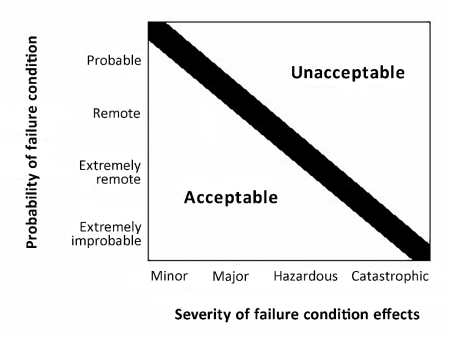
b. The classification of the failure conditions associated with the severity of their effects are described in Figure 2a.
The safety objectives associated with failure conditions are described in Figure 2b.
Figure 2a: Relationship Between Severity of the Effects and Classification of Failure Conditions
|
Effect on Aeroplane |
No effect on operational capabilities or safety |
Slight reduction in functional capabilities or safety margins |
Significant reduction in functional capabilities or safety margins |
Large reduction in functional capabilities or safety margins |
Normally with hull loss |
|
|
Effect on Occupants excluding Flight Crew |
Inconvenience |
Physical discomfort |
Physical distress, possibly including injuries |
Serious or fatal injury to a small number of passengers or cabin crew |
Multiple fatalities |
|
|
Effect on Flight Crew |
No effect on flight crew |
Slight increase in workload |
Physical discomfort or a significant increase in workload |
Physical distress or excessive workload impairs ability to perform tasks |
Fatalities or incapacitation |
|
|
Classification of Failure Conditions |
No Safety Effect |
Minor |
Major |
Hazardous |
Catastrophic |
|
Figure 2b: Relationship Between Classification of Failure Conditions and Probability
|
Classification of Failure Conditions |
No Safety Effect |
Minor |
Major |
Hazardous |
Catastrophic |
|
Allowable Qualitative Probability |
No Probability Requirement
|
<-Probable-> |
<--Remote--> |
Extremely <--------------> Remote |
Extremely Improbable |
|
Allowable Quantitative Probability: Average Probability per Flight Hour on the Order of: |
No Probability Requirement |
<-------------->
<10-3
Note 1 |
<-------------->
<10-5
|
<-------------->
<10-7
|
<10-9
|
|
Note 1: A numerical probability range is provided here as a reference. The applicant is not required to perform a quantitative analysis, nor substantiate by such an analysis, that this numerical criteria has been met for Minor Failure Conditions. Current transport category aeroplane products are regarded as meeting this standard simply by using current commonly‑accepted industry practice. |
|||||
c. The safety objectives associated with catastrophic failure conditions must be satisfied by demonstrating that:
(1) No single failure will result in a catastrophic failure condition; and
(2) Each catastrophic failure condition is extremely improbable; and
(3) Given that a single latent failure has occurred on a given flight, each catastrophic failure condition, resulting from two failures, either of which is latent for more than one flight, is remote.
9. COMPLIANCE WITH CS 25.1309.
This paragraph describes specific means of compliance for CS 25.1309. The applicant should obtain early concurrence of the certification authority on the choice of an acceptable means of compliance.
a. Compliance with CS 25.1309(a).
(1) Equipment covered by CS 25.1309(a)(1) must be shown to function properly when installed. The aeroplane operating and environmental conditions over which proper functioning of the equipment, systems, and installation is required to be considered includes the full normal envelope of the aeroplane as defined by the Aeroplane Flight Manual operating limitations together with any modification to that envelope associated with abnormal or emergency procedures. Other external environmental conditions such as atmospheric turbulence, HIRF, lightning, and precipitation, which the aeroplane is reasonably expected to encounter, should also be considered. The severity of the external environmental conditions, which should be considered, are limited to those established by certification standards and precedence.
(2) In addition to the external operating and environmental conditions, the effect of the environment within the aeroplane should be considered. These effects should include vibration and acceleration loads, variations in fluid pressure and electrical power, fluid or vapour contamination, due either to the normal environment or accidental leaks or spillage and handling by personnel. Document referenced in paragraph 3b(1) defines a series of standard environmental test conditions and procedures, which may be used to support compliance. Equipment covered by (CS) Technical Standard Orders containing environmental test procedures or equipment qualified to other environmental test standards can be used to support compliance. The conditions under which the installed equipment will be operated should be equal to or less severe than the environment for which the equipment is qualified.
(3) The required substantiation of the proper functioning of equipment, systems, and installations under the operating and environmental conditions approved for the aeroplane may be shown by test and/or analysis or reference to comparable service experience on other aeroplanes. It must be shown that the comparable service experience is valid for the proposed installation. For the equipment systems and installations covered by CS 25.1309(a)(1), the compliance demonstration should also confirm that the normal functioning of such equipment, systems, and installations does not interfere with the proper functioning of other equipment, systems, or installations covered by CS 25.1309(a)(1).
(4) The equipment, systems, and installations covered by CS 25.1309(a)(2) are typically those associated with amenities for passengers such as passenger entertainment systems, in-flight telephones, etc., whose failure or improper functioning in itself should not affect the safety of the aeroplane. Operational and environmental qualification requirements for those equipment, systems, and installations are reduced to the tests that are necessary to show that their normal or abnormal functioning does not adversely affect the proper functioning of the equipment, systems, or installations covered by CS 25.1309(a)(1) and does not otherwise adversely influence the safety of the aeroplane or its occupants. Examples of adverse influences are: fire, explosion, exposing passengers to high voltages, etc. Normal installation practices should result in sufficiently obvious isolation so that substantiation can be based on a relatively simple qualitative installation evaluation. If the possible impacts, including failure modes or effects, are questionable, or isolation between systems is provided by complex means, more formal structured evaluation methods may be necessary.
b. Compliance with CS 25.1309(b).
Paragraph 25.1309(b) requires that the aeroplane systems and associated components, considered separately and in relation to other systems, must be designed so that any catastrophic failure condition is extremely improbable and does not result from a single failure. It also requires that any hazardous failure condition is extremely remote, and that any major failure condition is remote. An analysis should always consider the application of the fail-safe design concept described in paragraph 6.b, and give special attention to ensuring the effective use of design techniques that would prevent single failures or other events from damaging or otherwise adversely affecting more than one redundant system channel or more than one system performing operationally similar functions.
(1) General. Compliance with the requirements of CS 25.1309(b) should be shown by analysis and, where necessary, by appropriate ground, flight, or simulator tests. Failure conditions should be identified and their effects assessed. The maximum allowable probability of the occurrence of each failure condition is determined from the failure condition’s effects, and when assessing the probabilities of failure conditions, appropriate analysis considerations should be accounted for. Any analysis must consider:
(i) Possible failure conditions and their causes, modes of failure, and damage from sources external to the system.
(ii) The possibility of multiple failures and undetected failures.
(iii) The possibility of requirement, design and implementation errors.
(iv) The effect of reasonably anticipated crew errors after the occurrence of a failure or failure condition.
(v) The effect of reasonably anticipated errors when performing maintenance actions.
(vi) The crew alerting cues, corrective action required, and the capability of detecting faults.
(vii) The resulting effects on the aeroplane and occupants, considering the stage of flight, the sequence of events/failures occurrence when relevant, and operating and environmental conditions.
(2) Planning. This AMC provides guidance on methods of accomplishing the safety objective. The detailed methodology needed to achieve this safety objective will depend on many factors, in particular the degree of systems complexity and integration. For aeroplanes containing many complex or integrated systems, it is likely that a plan will need to be developed to describe the intended process. This plan should include consideration of the following aspects:
(i) Functional and physical interrelationships of systems.
(ii) Determination of detailed means of compliance, which should include development assurance activities.
(iii) Means for establishing the accomplishment of the plan.
(3) Availability of Industry Standards and Guidance Materials. There are a variety of acceptable techniques currently being used in industry, which may or may not be reflected in the documents referenced in paragraphs 3.b(2) and 3.b(3). This AMC is not intended to compel the use of these documents during the definition of the particular method of satisfying the objectives of this AMC. However, these documents do contain material and methods of performing the system safety assessment. These methods, when correctly applied, are recognised by EASA as valid for showing compliance with CS 25.1309(b). In addition, the Document referenced in paragraph 3.b(3) contains tutorial information on applying specific engineering methods (e.g. Markov analysis, fault tree analysis) that may be utilised in whole or in part.
(4) Acceptable Application of Development Assurance Methods. Paragraph 9.b(1)(iii) above requires that any analysis necessary to demonstrate compliance with CS 25.1309(b) must consider the possibility of development errors. Errors made during the design and development of systems have traditionally been detected and corrected by exhaustive tests conducted on the system and its components, by direct inspection, and by other direct verification methods capable of completely characterising the performance of the system. These direct techniques may still be appropriate for systems containing non-complex items (i.e. items that are fully assured by a combination of testing and analysis) that perform a limited number of functions and that are not highly integrated with other aeroplane systems. For more complex or integrated systems, exhaustive testing may either be impossible because all of the system states cannot be determined or impractical because of the number of tests that must be accomplished. For these types of systems, compliance may be demonstrated by the use of development assurance. The level of development assurance (function development assurance level (FDAL)/item development assurance level (IDAL)) should be commensurate with the severity of the failure conditions the system is contributing to.
Guidelines, which may be used for the assignment of development assurance levels to aeroplanes and system functions (FDAL) and to items (IDAL), are described in the Document referenced in 3.b(2) above. Through this Document, EASA recognises that credit can be taken from system architecture (e.g. functional or item development independence) for the FDAL/IDAL assignment process.
Guidelines, which may be used for providing development assurance, are described for aeroplane and system development in the Document referenced in 3.b(2), and for software in the Document referenced in 3.a(3) above. (There is currently no agreed development assurance standard for airborne electronic hardware.)
(5) Crew and Maintenance Actions.
(i) Where an analysis identifies some indication to, and/or action by, the flight crew, cabin crew, or maintenance personnel, the following activities should be accomplished:
1 Verify that any identified indications are actually provided by the system. This includes the verification that the elements that provide detection (e.g. sensors, logic) properly trigger the indication under the relevant situations considering various causes, flight phases, operating conditions, operational sequences, and environments.
2 Verify that any identified indications will, in fact, be recognised.
3 Verify that any actions required have a reasonable expectation of being accomplished successfully and in a timely manner.
(ii) These verification activities should be accomplished by consulting with engineers, pilots, flight attendants, maintenance personnel, and human factors specialists, as appropriate, taking due consideration of any relevant service experience and the consequences if the assumed action is not performed or performed improperly.
(iii) In complex situations, the results of the review by specialists may need to be confirmed by simulator, ground tests, or flight tests. However, quantitative assessments of the probabilities of crew or maintenance errors are not currently considered feasible. If the failure indications are considered to be recognisable and the required actions do not cause an excessive workload, then for the purposes of the analysis, such corrective actions can be considered to be satisfactorily accomplished. If the necessary actions cannot be satisfactorily accomplished, the tasks and/or the systems need to be modified.
(6) Significant Latent Failures.
(i) Compliance with CS 25.1309(b)(4)
For compliance with CS 25.1309(b)(4), the hereafter systematic approach should be followed:
1. The applicant must first eliminate significant latent failures to the maximum practical extent utilising the current state-of-the-art technology, e.g. implement practical and reliable failure monitoring and flight crew indication systems to detect failures that would otherwise be latent for more than one flight. Additional guidance is provided in AMC 25-19 Section 8, Design Considerations Related to Significant Latent Failures.
2. For each significant latent failure which cannot reasonably be eliminated, the applicant must minimise the exposure time by design utilising current state-of-the-art technology rather than relying on scheduled maintenance tasks at lengthy intervals, i.e. implementing pilot-initiated checks, or self-initiated checks (e.g. first flight of the day check, power-up built-in tests, other system automated checks).
3. When relying on scheduled maintenance tasks, quantitative as well as qualitative aspects need to be addressed when limiting the latency. Additional guidance is provided in AMC 25-19 Section 10, Identification of Candidate CMRs (CCMRs).
Note: For turbojet thrust reversing systems, the design configurations in paragraphs 8.b(2) and 8.b(3) of AMC 25.933(a)(1) have traditionally been considered to be acceptable to EASA for compliance with CS 25.1309(b)(4).
(ii) Compliance with CS 25.1309(b)(5)
When a catastrophic failure condition involves two failures, either one of which is latent for more than one flight, and cannot reasonably be eliminated, compliance with CS 25.1309(b)(5) is required. Following the proper application of CS 25.1309(b)(4), the failure conditions involving multiple significant latent failures are expected to be sufficiently unlikely such that the dual-failure situations addressed in CS 25.1309(b)(5) are the only remaining significant latent failures of concern.
These significant latent failures of concern should be highlighted to EASA as early as possible. The system safety assessment should explain why avoidance is not practical, and provide supporting rationale for the acceptability. Rationale should be based on the proposed design being state-of-the-art, past experience, sound engineering judgment, or other arguments, which led to the decision not to implement other potential means of avoidance (e.g. eliminating the significant latent failure or adding redundancy).
Two criteria are implemented in CS 25.1309(b)(5): limit latency and limit residual probability.
Limit latency is intended to limit the time of operating with one evident failure away from a catastrophic failure condition. This is achieved by requiring that the sum of the probabilities of the latent failures, which are combined with each evident failure, does not exceed 1/1 000. Taking one catastrophic failure condition at a time,
— in case an evident failure is combined only once in a dual failure combination of concern, the probability of the individual latent failure needs to comply with the 1/1 000 criterion;
— in case an evident failure is combined in multiple dual failure combinations of concern, the combined probabilities of the latent failures need to comply with the 1/1 000 criterion.
Limit residual probability is intended to limit the average probability per flight hour of the failure condition given the presence of a single latent failure. This is achieved by defining the residual probability to be ‘remote’. Residual probability is the combined average probability per flight hour of all the single active failures that result in the catastrophic failure condition assuming one single latent failure has occurred.
These requirements are applied in addition to CS 25.1309(b)(1), which requires that catastrophic failure conditions be shown to be extremely improbable and do not result from a single failure.
Appendix 5 provides simplified examples explaining how the limit latency and limit residual probability analysis might be applied.
For compliance with the 1/1 000 criterion, the probability of the latent failures of concern should be derived from the probability of the worst-case flight, i.e. the probability where the evident failure occurs in the last flight before the scheduled maintenance inspection, while the latent failure may have occurred in any flight between two consecutive scheduled maintenance inspections. When dealing with constant failure rates, the probability of the latent failure should be computed as the product of the maximum time during which the failure may be present (i.e. exposure time) and its failure rate, if this probability is less than or equal to 0.1.
c. Compliance with CS 25.1309(c).
CS 25.1309(c) requires that information concerning unsafe system operating conditions must be provided to the crew to enable them to take appropriate corrective action in a timely manner, thereby mitigating the effects to an acceptable level. Any system operating condition that, if not detected and properly accommodated by flight crew action, would contribute to or cause a hazardous or catastrophic failure condition should be considered to be an ‘unsafe system operating condition’. Compliance with this requirement is usually demonstrated by the analysis identified in paragraph 9.b(1) above, which also includes consideration of crew alerting cues, corrective action required, and the capability of detecting faults. The required information may be provided by dedicated indication and/or annunciation or made apparent to the flight crew by the inherent aeroplane/systems responses. When flight crew alerting is required, it must be provided in compliance with CS 25.1322. CS 25.1309(c) also requires that installed systems and equipment for use by the flight crew, including flight deck controls and information, be designed to minimise flight crew errors that could create additional hazards (in compliance with CS 25.1302).
(1) The required information will depend on the degree of urgency for recognition and corrective action by the crew. It should be in the form of:
(i) a warning, if immediate recognition and corrective or compensatory action by the crew is required;
(ii) a caution if immediate crew awareness is required and subsequent crew action will be required;
(iii) an advisory, if crew awareness is required and subsequent crew action may be required;
(iv) a message in the other cases.
CS 25.1322 (and AMC 25.1322) give further requirements (and guidance) on the characteristics of the information required (visual, aural) based on those different categories.
(2) When failure monitoring and indication are provided by a system, its reliability should be compatible with the safety objectives associated with the system function for which it provides that indication. For example, if the effects of having a system failure and not annunciating that system failure are catastrophic, the combination of the system failure with the failure of its annunciation must be extremely improbable. The loss of annunciation itself should be considered a failure condition, and particular attention should be paid to the impact on the ability of the flight crew to cope with the subject system failure. In addition, unwanted operation (e.g. nuisance warnings) should be assessed. The failure monitoring and indication should be reliable, technologically feasible, and economically practical. Reliable failure monitoring and indication should utilise current state-of-the-art technology to maximise the probability of detecting and indicating genuine failures while minimising the probability of falsely detecting and indicating non-existent failures. Any indication should be timely, obvious, clear, and unambiguous.
(3) In the case of aeroplane conditions requiring immediate crew action, a suitable warning indication must be provided to the crew, if not provided by inherent aeroplane characteristics. In either case, any warning should be rousing and should occur at a point in a potentially catastrophic sequence where the aeroplane's capability and the crew's ability still remain sufficient for effective crew action.
(4) Unless they are accepted as normal airmanship, procedures for the crew to follow after the occurrence of failure warning should be described in the approved Aeroplane Flight Manual (AFM) or AFM revision or supplement.
(5) Even if operation or performance is unaffected or insignificantly affected at the time of failure, information to the crew is required if it is considered necessary for the crew to take any action or observe any precautions. Some examples include reconfiguring a system, being aware of a reduction in safety margins, changing the flight plan or regime, or making an unscheduled landing to reduce exposure to a more severe failure condition that would result from subsequent failures or operational or environmental conditions. Information is also required if a failure must be corrected before a subsequent flight. If operation or performance is unaffected or insignificantly affected, information and alerting indications may be inhibited during specific phases of flight where corrective action by the crew is considered more hazardous than no action.
(6) The use of periodic maintenance or flight crew checks to detect significant latent failures when they occur is undesirable and should not be used in lieu of practical and reliable failure monitoring and indications. When this is not accomplished, refer to paragraph 9.b(6) for guidance.
Paragraph 12 provides further guidance on the use of periodic maintenance or flight crew checks. Comparison with similar, previously approved systems is sometimes helpful. However, if a new technical solution allows practical and reliable failure monitoring and indications, this should be preferred in lieu of periodic maintenance or flight crew checks.
(7) Particular attention should be given to the placement of switches or other control devices, relative to one another, so as to minimise the potential for inadvertent incorrect crew action, especially during emergencies or periods of high workload. Extra protection, such as the use of guarded switches, may sometimes be needed.
10. IDENTIFICATION OF FAILURE CONDITIONS AND CONSIDERATIONS WHEN ASSESSING THEIR EFFECTS.
a. Identification of Failure Conditions.
Failure conditions should be identified by considering the potential effects of failures on the aeroplane and occupants. These should be considered from two perspectives:
(1) by considering failures of aeroplane-level functions — failure conditions identified at this level are not dependent on the way the functions are implemented and the systems' architecture.
(2) by considering failures of functions at the system level — these failure conditions are identified through examination of the way that functions are implemented and the systems' architectures. It should be noted that a failure condition might result from a combination of lower-level failure conditions. This requires that the analysis of complex, highly integrated systems, in particular, should be conducted in a highly methodical and structured manner to ensure that all significant failure conditions, that arise from multiple failures and combinations of lower-level failure conditions, are properly identified and accounted for. The relevant combinations of failures and failure conditions should be determined by the whole safety assessment process that encompasses the aeroplane and system level functional hazard assessments and common-cause analyses. The overall effect on the aeroplane of a combination of individual system failure conditions occurring as a result of a common or cascade failure, may be more severe than the individual system effect. For example, failure conditions classified as minor or major by themselves may have hazardous effects at an aeroplane level, when considered in combination.
b. Identification of Failure Conditions Using a Functional Hazard Assessment.
(1) Before a detailed safety assessment is proceeded with, a functional hazard assessment (FHA) of the aeroplane and system functions to determine the need for and scope of subsequent analysis should be prepared. This assessment may be conducted using service experience, engineering and operational judgement, and/or a top-down deductive qualitative examination of each function. An FHA is a systematic, comprehensive examination of aeroplane and system functions to identify potential minor, major, hazardous, and catastrophic failure conditions that may arise, not only as a result of malfunctions or failure to function, but also as a result of normal responses to unusual or abnormal external factors. It is concerned with the operational vulnerabilities of systems rather than with a detailed analysis of the actual implementation.
(2) Each system function should be examined with respect to the other functions performed by the system, because the loss or malfunction of all functions performed by the system may result in a more severe failure condition than the loss of a single function. In addition, each system function should be examined with respect to functions performed by other aeroplane systems, because the loss or malfunction of different but related functions, provided by separate systems may affect the severity of Failure Conditions postulated for a particular system.
(3) The FHA is an engineering tool, which should be performed early in the design and updated as necessary. It is used to define the high-level aeroplane or system safety objectives that must be considered in the proposed system architectures. It should also be used to assist in determining the development assurance levels for the systems. Many systems may need only a simple review of the system design by the applicant to determine the hazard classification. An FHA requires experienced engineering judgement and early co-ordination between the applicant and the certification authority.
(4) Depending on the extent of functions to be examined and the relationship between functions and systems, different approaches to FHA may be taken. Where there is a clear correlation between functions and systems, and where system, and hence function, interrelationships are relatively simple, it may be feasible to conduct separate FHAs for each system, providing any interface aspects are properly considered and are easily understood. Where system and function interrelationships are more complex, a top-down approach, from an aeroplane-level perspective, should be taken in planning and conducting FHAs However, with the increasing integrated system architectures, this traditional top-down approach should be performed in conjunction with common-cause considerations (e.g. common resources) in order to properly address the cases where one system contributes to several aeroplane-level functions.
c. Considerations When Assessing Failure Condition Effects.
The requirements of CS 25.1309(b) are intended to ensure an orderly and thorough evaluation of the effects on safety of foreseeable failures or other events, such as errors or external circumstances, separately or in combination, involving one or more system functions. The interactions of these factors within a system and among relevant systems should be considered.
In assessing the effects of a failure condition, factors which might alleviate or intensify the direct effects of the initial failure condition should be considered. Some of these factors include consequent or related conditions existing within the aeroplane that may affect the ability of the crew to deal with direct effects, such as the presence of smoke, acceleration effects, interruption of communication, interference with cabin pressurisation, etc. When assessing the consequences of a given failure condition, account should be taken of the failure information provided, the complexity of the crew action, and the relevant crew training. The number of overall failure conditions involving other than instinctive crew actions may influence the flight crew performance that can be expected. Training recommendations may need to be identified in some cases.
(1) The severity of failure conditions should be evaluated according to the following:
(i) Effects on the aeroplane, such as reductions in safety margins, degradation in performance, loss of capability to conduct certain flight operations, reduction in environmental protection, or potential or consequential effects on structural integrity. When the effects of a failure condition are difficult to assess, the hazard classification may need to be validated by tests, simulation, or other appropriate analytical techniques.
(ii) Effects on the crewmembers, such as increases above their normal workload that would affect their ability to cope with adverse operational or environmental conditions or subsequent failures.
(iii) Effects on the occupants, i.e., passengers and crewmembers.
(2) For convenience in conducting design assessments, failure conditions may be classified according to the severity of their effects as ‘no safety effect’, ‘minor’, ‘major’, ‘hazardous’, or ‘catastrophic’. Paragraph 7.a above provides accepted definitions of these terms.
(i) The classification of failure conditions does not depend on whether or not a system or function is the subject of a specific requirement or regulation. Some ʽrequired’ systems, such as transponders, position lights, and public address systems, may have the potential for only minor failure conditions. Conversely, other systems which are not ʽrequired’, such as auto-flight systems, may have the potential for ‘major’, ‘hazardous’, or ‘catastrophic failure conditions’.
(ii) Regardless of the types of assessment used, the classification of failure conditions should always be accomplished with consideration of all relevant factors; e.g., system, crew, performance, operational, external. It is particularly important to consider factors that would alleviate or intensify the severity of a failure condition. When flight duration, flight phase, or diversion time can adversely affect the classification of failure conditions, they must be considered to be intensifying factors. Other intensifying factors include conditions that are not related to the failure (such as weather or adverse operational or environmental conditions), and which reduce the ability of the flight crew to cope with a failure condition. An example of an alleviating factor would be the continued performance of identical or operationally similar functions by other systems not affected by the failure condition. Another example of an alleviating factor is the ability of the flight crew to recognise the failure condition and take action to mitigate its effects. Whenever this is taken into account, particular attention should be paid to the detection means to ensure that the ability of the flight crew (including physical ability and timeliness of the response) to detect the failure condition and take the necessary corrective action(s) is sufficient. Refer to CS 25.1309(c) and paragraph 9.c of this AMC for more detailed guidance on crew annunciations and crew response evaluation. Combinations of intensifying or alleviating factors need to be considered only if they are anticipated to occur together.
11. ASSESSMENT OF FAILURE CONDITION PROBABILITIES AND ANALYSIS CONSIDERATIONS.
After the failure conditions have been identified and the severity of the effects of the failure conditions have been assessed, there is a responsibility to determine how to show compliance with the requirement and obtain the concurrence of EASA. Design and installation reviews, analyses, flight tests, ground tests, simulator tests, or other approved means may be used.
a. Assessment of Failure Condition Probabilities.
(1) The probability that a failure condition would occur may be assessed as probable, remote, extremely remote, or extremely improbable. These terms are defined in paragraph 7. Each failure condition should have a probability that is inversely related to the severity of its effects as described in paragraph 8.
(2) When a system provides protection from events (e.g., cargo compartment fire, gusts), its reliability should be compatible with the safety objectives necessary for the failure condition associated with the failure of the protection system and the probability of such events. (See paragraph 11g of this AMC and Appendix 4.)
(3) An assessment to identify and classify failure conditions is necessarily qualitative. On the other hand, an assessment of the probability of a failure condition may be either qualitative or quantitative. An analysis may range from a simple report that interprets test results or compares two similar systems to a detailed analysis that may or may not include estimated numerical probabilities. The depth and scope of an analysis depends on the types of functions performed by the system, the severity of failure conditions, and whether or not the system is complex.
(4) Experienced engineering and operational judgement should be applied when determining whether or not a system is complex. Comparison with similar, previously approved systems is sometimes helpful. All relevant systems’ attributes should be considered; however, the complexity of the software and hardware item need not be a dominant factor in the determination of complexity at the system level.
b. Single Failure Considerations.
(1) According to the requirements of CS 25.1309(b)(1)(ii), a catastrophic failure condition must not result from the failure of a single component, part, or element of a system. Failure containment should be provided by the system design to limit the propagation of the effects of any single failure to preclude catastrophic failure conditions. In addition, there must be no common-cause failure, which could affect both the single component, part, or element, and its failure containment provisions. A single failure includes any set of failures, which cannot be shown to be independent from each other. Common-cause failures (including common mode failures) and cascading failures should be evaluated as dependent failures from the point of the root cause or the initiator. Errors in development, manufacturing, installation, and maintenance can result in common-cause failures (including common mode failures) and cascading failures. They should, therefore, be assessed and mitigated in the frame of the common-cause and cascading failures consideration. Appendix 1 and the Document referenced in paragraph 3.b(3) describe types of common-cause analyses that may be conducted, to assure that independence is maintained. Failure containment techniques available to establish independence may include partitioning, separation, and isolation.
(2) While single failures must normally be assumed to occur, there are cases where it is obvious that, from a realistic and practical viewpoint, any knowledgeable, experienced person would unequivocally conclude that a failure mode simply would not occur, unless it is associated with a wholly unrelated failure condition that would itself be catastrophic. Once identified and accepted, such cases need not be considered failures in the context of CS 25.1309. For example, with simply loaded static elements, any failure mode, resulting from fatigue fracture, can be assumed to be prevented if this element is shown to meet the damage tolerance requirements of CS 25.571.
c. Common Cause Failure Considerations.
An analysis should consider the application of the fail-safe design concept described in paragraph 6b and give special attention to ensure the effective use of design and installation techniques that would prevent single failures or other events from damaging or otherwise adversely affecting more than one redundant system channel, more than one system performing operationally similar functions, or any system and an associated safeguard. When considering such common-cause failures or other events, consequential or cascading effects should be taken into account. Some examples of such potential common cause failures or other events would include rapid release of energy from concentrated sources such as uncontained failures of rotating parts (other than engines and propellers) or pressure vessels, pressure differentials, non-catastrophic structural failures, loss of environmental conditioning, disconnection of more than one subsystem or component by over temperature protection devices, contamination by fluids, damage from localised fires, loss of power supply or return (e.g. mechanical damage or deterioration of connections), excessive voltage, physical or environmental interactions among parts, errors, or events external to the system or to the aeroplane (see Document referenced in paragraph 3b(3)).
d. Depth of Analysis.
The following identifies the depth of analysis expected based on the classification of a failure condition.
(1) No Safety Effect Failure Conditions. An FHA, with a design and installation appraisal, to establish independence from other functions is necessary for the safety assessment of these failure conditions. If it is chosen not to do an FHA, the safety effects may be derived from the design and installation appraisal.
(2) Minor Failure Conditions. An FHA, with a design and installation appraisal, to establish independence from other functions is necessary for the safety assessment of these failure conditions. Combinations of failure condition effects, as noted in paragraph 10 above, must also be considered. If it is chosen not to do an FHA, the safety effects may be derived from the design and installation appraisal.
(3) Major Failure Conditions. Major failure conditions must be remote:
(i) If the system is similar in its relevant attributes to those used in other aeroplanes and the effects of failure would be the same, then design and installation appraisals (as described in Appendix 1), and satisfactory service history of the equipment being analysed, or of similar design, will usually be acceptable for showing compliance.
(ii) For systems that are not complex, where similarity cannot be used as the basis for compliance, then compliance may be shown by means of a qualitative assessment that shows that the system-level major failure conditions, of the system as installed, are consistent with the FHA and are remote, e.g. redundant systems.
(iii) For complex systems without redundancy, compliance may be shown as in paragraph 11.d(3)(ii) of this AMC. To show that malfunctions are indeed remote in systems of high complexity without redundancy (for example, a system with a self-monitoring microprocessor), it is sometimes necessary to conduct a qualitative functional failure modes and effects analysis (FMEA) supported by failure rate data and fault detection coverage analysis.
(iv) An analysis of a redundant system is usually complete if it shows isolation between redundant system channels and satisfactory reliability for each channel. For complex systems where functional redundancy is required, a qualitative FMEA and qualitative fault tree analysis may be necessary to determine that redundancy actually exists (e.g. no single failure affects all functional channels).
(4) Hazardous and Catastrophic Failure Conditions.
Hazardous failure conditions must be extremely remote, and catastrophic failure conditions must be extremely improbable:
(i) Except as specified in paragraph 11.d(4)(ii) below, a detailed safety analysis will be necessary for each hazardous and catastrophic failure condition identified by the FHA. The analysis will usually be a combination of qualitative and quantitative assessment of the design.
(ii) For very simple and conventional installations, i.e. low complexity and similarity in relevant attributes, it may be possible to assess a hazardous or catastrophic failure condition as being extremely remote or extremely improbable, respectively, on the basis of experienced engineering judgement, using only qualitative analysis. The basis for the assessment will be the degree of redundancy, the established independence and isolation of the channels and the reliability record of the technology involved. Satisfactory service experience on similar systems commonly used in many aeroplanes may be sufficient when a close similarity is established in respect of both the system design and operating conditions.
(iii) For complex systems where true similarity in all relevant attributes, including installation attributes, can be rigorously established, it may be also possible to assess a hazardous or catastrophic failure condition as being extremely remote or extremely improbable, respectively, on the basis of experienced engineering judgement, using only qualitative analysis. A high degree of similarity in both design and application is required to be substantiated.
e. Calculation of Average Probability per Flight Hour (Quantitative Analysis).
(1) The average probability per flight hour is the probability of occurrence, normalised by the flight time, of a failure condition during a flight, which can be seen as an average over all possible flights of the fleet of aeroplane to be certified. The calculation of the average probability per flight hour for a failure condition should consider:
(i) the average flight duration and the average flight profile for the aeroplane type to be certified,
(ii) all combinations of failures and events that contribute to the failure condition,
(iii) the conditional probability if a sequence of events is necessary to produce the failure condition,
(iv) the relevant ʽat risk’ time if an event is only relevant during certain flight phases, and
(v) the exposure time if the failure can persist for multiple flights.
(2) The details how to calculate the average probability per flight hour for a failure condition are given in Appendix 3 of this AMC.
(3) If the probability of a subject failure condition occurring during a typical flight of mean duration for the aeroplane type divided by the flight’s mean duration in hours is likely to be significantly different from the predicted average rate of occurrence of that failure condition during the entire operational life of all aeroplanes of that type, then a risk model that better reflects the failure condition should be used.
(4) It is recognised that, for various reasons, component failure rate data are not precise enough to enable accurate estimates of the probabilities of failure conditions. This results in some degree of uncertainty, as indicated by the wide line in Figure 1, and the expression ʽon the order of’ in the descriptions of the quantitative probability terms that are provided above. When calculating the estimated probability of each failure condition, this uncertainty should be accounted for in a way that does not compromise safety.
f. Integrated Systems.
Interconnections between systems have been a feature of aeroplane design for many years and CS 25.1309(b) recognises this in requiring systems to be considered in relation to other systems. Providing the interfaces between systems are relatively few and simple, and hence readily understandable, compliance may often be demonstrated through a series of system safety assessments, each of which deals with a particular failure condition (or more likely a group of failure conditions) associated with a system and, where necessary, takes account of failures arising at the interface with other systems. This procedure has been found to be acceptable in many past certification programmes. However, where the systems and their interfaces become more complex and extensive, the task of demonstrating compliance may become more complex. It is therefore essential that the means of compliance be considered early in the design phase to ensure that the design can be supported by a viable safety assessment strategy. Aspects of the guidance material covered elsewhere in this AMC and which should be given particular consideration are as follows:
(1) planning the proposed means of compliance; this should include development assurance activities to mitigate the occurrence of errors in the design,
(2) considering the importance of architectural design in limiting the impact and propagation of failures,
(3) the potential for common-cause failures and cascade effects and the possible need to assess combinations of multiple lower-level (e.g. major) failure conditions,
(4) the importance of multidisciplinary teams in identifying and classifying significant failure conditions,
(5) effect of crew and maintenance procedures in limiting the impact and propagation of failures.
In addition, rigorous and well-structured design and development procedures play an essential role in facilitating a methodical safety assessment process and providing visibility to the means of compliance. Document referenced in paragraph 3b(2) may be helpful in the certification of highly integrated or complex aircraft systems.
g. Operational or Environmental Conditions.
A probability of one should usually be used for encountering a discrete condition for which the aeroplane is designed, such as instrument meteorological conditions or Category III weather operations. However, Appendix 4 contains allowable probabilities, which may be assigned to various operational and environmental conditions for use in computing the average probability per flight hour of failure conditions without further justification. Single failures, which, in combination with operational or environmental conditions, lead to catastrophic failure conditions, are, in general, not acceptable.
Limited cases that are properly justified may be considered on a case-by-case basis (e.g. operational events or environmental conditions that are extremely remote).
Appendix 4 is provided for guidance and is not intended to be exhaustive or prescriptive. At this time, a number of items have no accepted standard statistical data from which to derive a probability figure. However, these items are included for either future consideration or as items for which the applicant may propose a probability figure supported by statistically valid data or supporting service experience. The applicant may propose additional conditions or different probabilities from those in Appendix 4 provided they are based on statistically valid data or supporting service experience. The applicant should obtain early concurrence of EASA when such conditions are to be included in an analysis. When combining the probability of such a random condition with that of a system failure, care should be taken to ensure that the condition and the system failure are independent of one another, or that any dependencies are properly accounted for.
h. Justification of Assumptions, Data Sources and Analytical Techniques.
(1) Any analysis is only as accurate as the assumptions, data, and analytical techniques it uses. Therefore, to show compliance with the requirements, the underlying assumptions, data, and analytic techniques should be identified and justified to assure that the conclusions of the analysis are valid. Variability may be inherent in elements such as failure modes, failure effects, failure rates, failure probability distribution functions, failure exposure times, failure detection methods, fault independence, limitation of analytical methods, processes, and assumptions. The justification of the assumptions made with respect to the above items should be an integral part of the analysis. Assumptions can be validated by using experience with identical or similar systems or components with due allowance made for differences of design, duty cycle and environment. Where it is not possible to fully justify the adequacy of the safety analysis and where data or assumptions are critical to the acceptability of the Failure Condition, extra conservatism should be built into either the analysis or the design. Alternatively any uncertainty in the data and assumptions should be evaluated to the degree necessary to demonstrate that the analysis conclusions are insensitive to that uncertainty.
(2) Where adequate validation data is not available (e.g., new or novel systems), and extra conservatism is built into the analysis, then the normal post-certification in-service follow-up may be performed to obtain the data necessary to alleviate any consequence of the extra conservatism. This data may be used, for example, to extend system check intervals.
12. OPERATIONAL AND MAINTENANCE CONSIDERATIONS.
This AMC addresses only those operational and maintenance considerations that are directly related to compliance with CS 25.1309; other operational and maintenance considerations are not discussed herein. Flight crew and maintenance tasks related to compliance with this requirement should be appropriate and reasonable. However, quantitative assessments of crew errors are not considered feasible. Therefore, reasonable tasks are those for which full credit can be taken because they can realistically be anticipated to be performed correctly when they are required or scheduled. In addition, based on experienced engineering and operational judgement, the discovery of obvious failures during normal operation or maintenance of the aeroplane may be assumed, even though identification of such failures is not the primary purpose of the operational or maintenance actions.
a. Flight Crew Action.
When assessing the ability of the flight crew to cope with a failure condition, the information provided to the crew and the complexity of the required action should be considered. When considering the information provided to the flight crew, refer also to paragraph 9.c (compliance with CS 25.1309(c)). Credit for flight crew actions, and considerations of flight crew errors, should be consistent with relevant service experience and acceptable human factors evaluations. If the evaluation indicates that a potential failure condition can be alleviated or overcome without jeopardising other safety-related flight crew tasks and without requiring exceptional pilot skill or strength, credit may be taken for both qualitative and quantitative assessments. Similarly, credit may be taken for correct flight crew performance of the periodic checks required to demonstrate compliance with CS 25.1309(b) provided overall flight crew workload during the time available to perform them is not excessive and they do not require exceptional pilot skill or strength. Unless flight crew actions are accepted as normal airmanship, they should be described in the approved Aeroplane Flight Manual in compliance with CS 25.1585. The applicant should provide a means to ensure that the AFM will contain the required flight crew actions that have been used as mitigation factors in the hazard classification or that have been taken as assumptions to limit the exposure time of failures.
b. Maintenance Action.
Credit may be taken for the correct accomplishment of reasonable maintenance tasks, for both qualitative and quantitative assessments. The maintenance tasks needed to demonstrate compliance with CS 25.1309(b) should be established. In doing this, the following maintenance scenarios can be used:
(1) For failures known to the flight crew, refer to paragraph 12.d.
(2) Latent failures will be identified by a scheduled maintenance task. If this approach is taken, and the failure condition is hazardous or catastrophic, then a CCMR maintenance task should be established. Some latent failures can be assumed to be identified based upon return to service test on the LRU following its removal and repair (component mean time between failures (MTBF) should be the basis for the check interval time).
c. Candidate Certification Maintenance Requirements.
(1) By detecting the presence of, and thereby limiting the exposure time to significant latent failures that would, in combination with one or more other specific failures or events identified by safety analysis, result in a hazardous or catastrophic failure condition, periodic maintenance or flight crew checks may be used to help show compliance with CS 25.1309(b). Where such checks cannot be accepted as basic servicing or airmanship they become CCMRs. AMC 25.19 details the handling of CCMRs.
(2) Rational methods, which usually involve quantitative analysis, or relevant service experience should be used to determine check intervals. This analysis contains inherent uncertainties as discussed in paragraph 11e(3). Where periodic checks become CMRs these uncertainties justify the controlled escalation or exceptional short-term extensions to individual CMRs allowed under AMC 25.19.
d. Flight with Equipment or Functions known to be Inoperative.
An applicant may elect to develop a list of equipment and functions that need not be operative for flight, based on stated compensating precautions that should be taken, e.g. operational or time limitations, flight crew procedures, or ground crew checks. The documents used to demonstrate compliance with CS 25.1309, together with any other relevant information, should be considered in the development of this list. Experienced engineering and operational judgement should be applied during the development of this list. When operation is envisaged with equipment that is known to be inoperative, and this equipment affects the probabilities associated with hazardous and/or catastrophic failure conditions, limitations may be needed on the number of flights and/or the allowed operation time with such inoperative equipment. These limitations should be established in accordance with the recommendations contained in CS-MMEL.
13. ASSESSMENT OF MODIFICATIONS TO PREVIOUSLY CERTIFICATED AEROPLANES.
The means to assure continuing compliance with CS 25.1309 for modifications to previously certificated aeroplanes should be determined on a case-by-case basis and will depend on the applicable aeroplane certification basis and the extent of the change being considered. The change could be a simple modification affecting only one system or a major redesign of many systems, possibly incorporating new technologies. The minimal effort for demonstrating compliance to 25.1309 for any modification is an assessment of the impact on the original system safety assessment. The result of this assessment may range from a simple statement that the existing system safety assessment still applies to the modified system in accordance with the original means of compliance, to the need for new means of compliance encompassing the plan referred to in paragraph 9b. (STC applicants, if the TC holder is unwilling to release or transfer proprietary data in this regard, the STC applicant may have to create the System Safety Assessment. Further guidance may be found in paragraph 6 of Document referenced in paragraph 3b(2).) It is recommended that the Agency be contacted early to obtain agreement on the means of compliance.
[Amdt 25/2]
[Amdt 25/4]
[Amdt 25/8]
[Amdt 25/11]
[Amdt 25/12]
[Amdt 25/14]
[Amdt 25/19]
[Amdt 25/24]
[Amdt 25/27]
Appendix 1 – Assessment methods
ED Decision 2020/001/R
Various methods for assessing the causes, severity, and probability of failure conditions are available to support experienced engineering and operational judgement. Some of these methods are structured. The various types of analysis are based on either inductive or deductive approaches. Probability assessments may be qualitative or quantitative. Descriptions of some types of analysis are provided below and in Document referenced in paragraph 3b(3).
a. Design Appraisal. This is a qualitative appraisal of the integrity and safety of the system design.
b. Installation Appraisal. This is a qualitative appraisal of the integrity and safety of the installation. Any deviations from normal, industry accepted installation practices, such as clearances or tolerances, should be evaluated, especially when appraising modifications made after entry into service.
c. Failure Modes and Effects Analysis. This is a structured, inductive, bottom-up analysis, which is used to evaluate the effects on the system and the aeroplane of each possible element or component failure. When properly formatted, it will aid in identifying latent failures and the possible causes of each failure mode. Document referenced in paragraph 3b(3) provides methodology and detailed guidelines, which may be used to perform this type of analysis. A FMEA could be apiece part FMEA or a functional FMEA. For modern microcircuit based LRUs and systems an exhaustive piece part FMEA is not practically feasible with the present state of the art. In that context, a FMEA may be more functional than piece part oriented. A functional oriented FMEA can lead to uncertainties in the qualitative and quantitative aspects, which can be compensated for by more conservative assessment such as:
— assuming all failure modes result in the failure conditions of interest,
— careful choice of system architecture,
— taking into account the experience lessons learned on the use of similar technology.
d. Fault Tree or Dependence Diagram Analysis. Structured, deductive, top-down analyses that are used to identify the conditions, failures, and events that would cause each defined failure condition. They are graphical methods of identifying the logical relationship between each particular failure condition and the primary element or component failures, other events, or combinations thereof that can cause it. A failure modes and effects analysis may be used as the source document for those primary failures or other events.
e. Markov Analysis. A Markov model (chain) represents various system states and the relationships among them. The states can be either operational or non-operational. The transitions from one state to another are a function of the failure and repair rates. Markov analysis can be used as a replacement for fault tree/dependence diagram analysis, but it often leads to more complex representation, especially when the system has many states. It is recommended that Markov analysis be used when fault tree or dependence diagrams are not easily usable, namely to take into account complex transition states of systems which are difficult to represent and handle with classical fault tree or dependence diagram analysis.
f. Common-Cause Analysis. The acceptance of adequate probability of failure conditions is often derived from the assessment of multiple systems based on the assumption that failures are independent. Therefore, it is necessary to recognise that such independence may not exist in the practical sense and specific studies are necessary to ensure that independence can either be assured or considered to be acceptable. These studies may also identify a combination of failures and effects that would otherwise not have been foreseen by FMEA or fault tree analysis.
The common cause analysis is subdivided into three areas of study:
(1) Zonal Safety Analysis. This analysis has the objective of ensuring that the equipment installations within each zone of the aeroplane are at an adequate safety standard with respect to design and installation standards, interference between systems, and maintenance errors. In those areas of the aeroplane where multiple systems and components are installed in close proximity, it should be ensured that the zonal analysis would identify any failure or malfunction which by itself is considered sustainable but which could have more serious effects when adversely affecting other adjacent systems or components.
(2) Particular Risk Analysis. Particular risks are defined as those events or influences, which are outside the systems concerned. Examples are fire, leaking fluids, bird strike, tire burst, high intensity radiated fields exposure, lightning, uncontained failure of high energy rotating machines, etc. Each risk should be the subject of a specific study to examine and document the simultaneous or cascading effects or influences, which may violate independence.
(3) Common Mode Analysis. This analysis is performed to confirm the assumed independence of the events, which were considered in combination for a given failure condition. The effects of specification, design, implementation, installation, maintenance, and manufacturing errors, environmental factors other than those already considered in the particular risk analysis, and failures of system components should be considered.
g. Safety Assessment Process. Appendix 2 provides an overview of the safety assessment process.
[Amdt 25/14]
[Amdt 25/24]
Appendix 2 – Safety Assessment Process Overview
ED Decision 2020/001/R
In showing compliance with CS 25.1309(b), the considerations covered in this AMC should be addressed in a methodical and systematic manner, which ensures that the process and its findings are visible and readily assimilated. This appendix is provided primarily for those who are not familiar with the various methods and procedures generally used in the industry to conduct safety assessments. This guide and Figures A2-1 and A2-2 are not certification checklists, and they do not include all the information provided in this AMC. There is no necessity for them to be used or for the Agency to accept them, in whole or in part, to show compliance with any regulation. Their sole purposes are to assist, by illustrating a systematic approach to safety assessments, to enhance understanding and communication by summarising some of the information provided in this AMC, and to provide some suggestions on documentation. More detailed guidance can be found in Document referenced in paragraph 3b(3). Document referenced in paragraph 3b(2) includes additional guidance on how the safety assessment process relates to the system development process.
a. Define the system and its interfaces, and identify the functions that the system is to perform. Some functions are intended to be protective, i.e. functions preventing the failures in system X from adversely affecting system Y. As the implementation of the functional requirements becomes more developed, care should be taken to identify all protective functions upon which airworthiness will depend. Determine whether or not the system is complex, similar to systems used on other aeroplanes, or conventional. When multiple systems and functions are to be evaluated, consider the relationships between multiple safety assessments.
b. Identify and classify failure conditions. All relevant engineering organisations, such as systems, structures, propulsion, and flight test, should be involved in this process. This identification and classification may be done by conducting an FHA, which is usually based on one of the following methods, as appropriate:
(1) If the system is not complex and its relevant attributes are similar to those of systems used on other aeroplanes, the identification and classification may be derived from design and installation appraisals and the service experience of the comparable, previously approved systems.
(2) If the system is complex, it is necessary to systematically postulate the effects on the safety of the aeroplane and its occupants resulting from any possible failures, considered both individually and in combination with other failures or events.
c. Choose the means to be used to determine compliance with CS 25.1309. The depth and scope of the analysis depends on the types of functions performed by the system, the severity of system failure conditions, and whether or not the system is complex (see Figure A2-2). For major failure conditions, experienced engineering and operational judgement, design and installation appraisals and comparative service experience data on similar systems may be acceptable, either on their own or in conjunction with qualitative analyses or selectively used quantitative analyses. For hazardous or catastrophic failure conditions, a very thorough safety assessment is necessary. The early concurrence of EASA on the choice of an acceptable means of compliance should be obtained.
d. Conduct the analysis and produce the data, which are agreed with the certification authority as being acceptable to show compliance. A typical analysis should include the following information to the extent necessary to show compliance:
(1) A statement of the functions, boundaries, and interfaces of the system.
(2) A list of the parts and equipment of which the system is comprised, including their performance specifications or design standards and development assurance levels if applicable. This list may reference other documents, e.g., European Technical Standard Orders (ETSOs), manufacturers or military specifications, etc.
(3) The conclusions, including a statement of the failure conditions and their classifications and probabilities (expressed qualitatively or quantitatively, as appropriate) that show compliance with the requirements of CS 25.1309.
(4) A description that establishes correctness and completeness and traces the work leading to the conclusions. This description should include the basis for the classification of each failure condition (e.g. analysis or ground, flight, or simulator tests). It should also include a description of precautions taken against common-cause failures, provide any data such as component failure rates and their sources and applicability, support any assumptions made, and identify any required flight crew or ground crew actions, including any CCMRs.
e. Assess the analyses and conclusions of multiple safety assessments to ensure compliance with the requirements for all aeroplane-level failure conditions.
f. Prepare compliance statements, maintenance requirements, and flight manual requirements.
Figure A2-1: Safety Assessment Process Overview
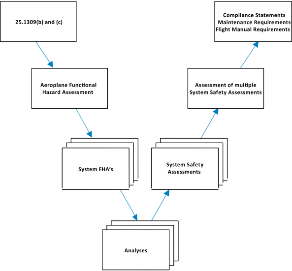
Figure A2-2: Depth of Analysis Flowchart
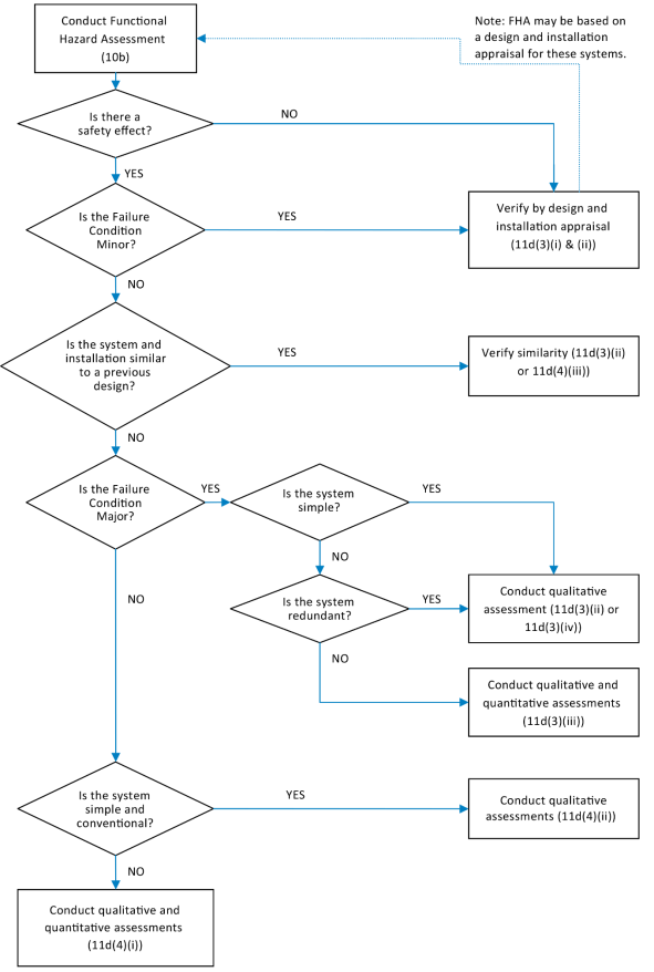
[Amdt 25/2]
[Amdt 25/12]
[Amdt 25/14]
[Amdt 25/24]
Appendix 3 – Calculation of the average probability per flight hour
ED Decision 2021/015/R
The purpose of this material is to provide guidance for calculating the ʽAverage Probability per Flight Hour’ for a failure condition so that it can be compared with the quantitative criteria of the AMC.
The process of calculating the ʽAverage Probability per Flight Hour’ for a failure condition will be described as a four-step process and is based on the assumption that the life of an aeroplane is a sequence of ʽAverage Flights’.
Step 1: Determination of the ʽAverage Flight’
Step 2: Calculation of the probability of a failure condition for a certain ʽAverage Flight’
Step 3: Calculation of the ʽAverage Probability per Flight’ of a failure condition
Step 4: Calculation of the ʽAverage Probability Per Flight Hour’ of a failure condition
a. Determination of the "Average Flight”. The "Average Probability per Flight Hour" is to be based on an "Average Flight". The average flight duration and average flight profile for the fleet of aeroplane to be certified should be estimated. The average flight duration should be estimated based on expectations and historical experience for similar types. The "Average Flight" duration should reflect the best estimate of the cumulative flight hours divided by the cumulative aeroplane flights for the service life of the aeroplane. The "Average Flight" profile should be based on the operating weight and performance expectations for the average aeroplane when flying a flight of average duration in an ICAO standard atmosphere. The duration of each flight phase (e.g. takeoff, climb, cruise, descent, approach and landing) in the "Average Flight" should be based on the average flight profile. Average taxi times for departure and arrival at an average airport should be considered where appropriate and added to the average flight time. The "Average Flight" duration and profile should be used as the basis for determining the "Average Probability per Flight Hour" for a quantitative safety assessment.
b. Calculation of the Probability of a Failure Condition for a certain ʽAverage Flight’. The probability of a failure condition occurring on an ʽAverage Flight’ PFlight(failure condition) should be determined by structured methods (see Document referenced in paragraph 3.b(3) for example methods) and should consider all significant elements (e.g. combinations of failures and events) that contribute to the failure condition. The following should be considered:
(1) The component failure rates utilised in calculating the ʽAverage Probability per Flight Hour’ should be estimates of the mature constant failure rates after infant mortality and prior to wear-out. For components whose probability of failure may be associated with non-constant failure rates within the operational life of the aeroplane, a reliability analysis may be used to determine component replacement times (e.g. Weibull analysis). In either case, the failure rate should be based on all causes of failure (operational, environmental, etc.). If available, service history of same or similar components in the same or similar environment should be used.
Ageing and wear of similarly constructed and similarly loaded redundant components, whose failure could lead directly, or in combination with one other failure, to a catastrophic or hazardous failure condition, should be assessed when determining scheduled maintenance tasks for such components.
The replacement times, necessary to mitigate the risk due to ageing and wear of such components within the operational life of the aeroplane, should be assessed through the same methodology like other scheduled maintenance tasks that are required to comply with CS 25.1309 (refer to AMC 25-19 for guidance) and documented in the Airworthiness Limitations Section of the Instructions for Continued Airworthiness, as appropriate.
(2) If the failure is only relevant during certain flight phases, the calculation should be based on the probability of failure during the relevant ‘at risk’ time for the ‘Average Flight’.
(3) If one or more failed elements in the system can persist for multiple flights (latent, dormant, or hidden failures), the calculation should consider the relevant exposure times (e.g. time intervals between maintenance and operational checks/ inspections). In such cases the probability of the Failure Condition increases with the number of flights during the latency period.
(4) If the failure rate of one element varies during different flight phases, the calculation should consider the failure rate and related time increments in such a manner as to establish the probability of the failure condition occurring on an ʽAverage Flight’:
It is assumed that the ʽAverage Flight’ can be divided into n phases (phase 1, ... , phase n). Let TF the ʽAverage Flight’ duration, Tj the duration of phase j and tj the transition point between Tj and Tj+1, j=1, ... ,n . I.e.
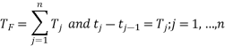
Let lj(t) the failure rate function during phase j, i.e. for t Î [tj-1,tj].
Remark: lj(t) may be equal 0 for all t Î [tj-1,tj] for a specific phase j.
Let PFlight (Failure) the probability that the element fails during one certain flight (including nonflying time) and PPhase j (Failure) the probability that the element fails in phase j.
Two cases are possible:
(i) The element is checked operative at the beginning of the certain flight. Then

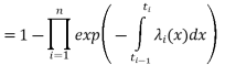
(ii) The state of the item is unknown at the beginning of the certain flight. Then
![]()
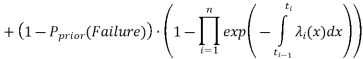
where Pprior (Failure) is the probability that the failure of the element has occurred prior to the certain flight.
(5) If there is only an effect when failures occur in a certain order, the calculation should account for the conditional probability that the failures occur in the sequence necessary to produce the failure condition.
c. Calculation of the Average Probability per Flight of a Failure Condition. The next step is to calculate the ʽAverage Probability per Flight’ for the failure condition, i.e. the probability of the failure condition for each flight (which might be different although all flights are ʽAverage Flights’) during the relevant time (e.g. the least common multiple of the exposure times or the aeroplane life) should be calculated, summed up and divided by the number of flights during that period. The principles of calculating are described below and also in more detail in the Document referenced in paragraph 3.b(3).
![]()
Where N is the quantity of all flights during the relevant time, and PFlightk is the probability that the Failure Condition occurs in flight k.
d. Calculation of the Average Probability per Flight Hour of a Failure Condition. Once the "Average Probability per Flight" has been calculated it should be normalised by dividing it by the "Average Flight" duration TF in Flight Hours to obtain the "Average Probability per Flight Hour". This quantitative value should be used in conjunction with the hazard category/effect established by the FHA to determine if it is compliant for the Failure Condition being analysed.
![]()
[Amdt 25/14]
[Amdt 25/24]
Amdt 25/27]
Appendix 4 – Allowable Probabilities
ED Decision 2020/001/R
The following probabilities may be used for environmental conditions and operational factors (not caused by aeroplane failures) in quantitative safety analyses:
Environmental Factors
|
Condition |
Model or other Justification |
Probability |
|
CS-25 Appendix C icing conditions |
|
1 |
|
CS-25 Appendix O icing conditions |
|
10-2 per flight hour |
|
Icing conditions beyond certified conditions (considered as ‘Severe icing’) |
|
No accepted standard data |
|
Head wind >25 kt during takeoff and landing |
AC 120-28 CS-AWO |
10-2 per flight |
|
Tail wind >10 kt during takeoff and landing |
AC 120-28 CS-AWO |
10-2 per flight |
|
Cross wind >20 kt during takeoff and landing |
AC 120-28 CS-AWO |
10-2 per flight |
|
Limit design gust and turbulence |
CS 25.341 (Under review by Structures Harmonisation Working Group) |
10-5 per flight hour |
|
Air temperature < -70°C |
|
No accepted standard data |
Aeroplane Configurations
|
Configuration |
Model or other Justification |
Probability |
|
Centre of gravity |
Standard industry practice |
Uniform over approved range |
|
Landing and Takeoff Weights/Masses |
Standard industry practice |
Uniform over approved range |
Flight Conditions
|
Condition |
Model or other Justification |
Probability |
|
Flight condition requiring Stall Warning |
Assumption |
10-2 per flight |
|
Flight condition resulting in a Stall |
Assumption |
10-5 per flight |
|
Excessiveness of VMO/MMO |
Assumption |
10-2 per flight |
|
Flight condition greater than or equal to 1.5 g |
|
No accepted standard data |
|
Flight condition less than or equal to 0 g |
|
No accepted standard data |
Mission Dependencies
|
Event |
Model or other Justification |
Probability |
|
Any rejected take-off |
|
No accepted standard data |
|
High energy rejected take-off |
|
No accepted standard data |
|
Need to jettison fuel |
|
No accepted standard data |
|
Go-around |
|
No accepted standard data |
Other Events
|
Event |
Model or other Justification |
Probability |
|
Fire in a lavatory not caused by aeroplane failures |
|
No accepted standard data |
|
Fire in a cargo compartment not caused by aeroplane failures |
|
No accepted standard data |
Notes:
1. If “No accepted standard data” appears in the above tables, the applicant must provide a justified value if a probability less than 1 is to be used in the analysis.
2. The probabilities quoted in this Appendix have been found to be appropriate for use in the context of a quantitative safety analysis performed to demonstrate compliance with CS 25.1309. They may not always be appropriate for use in the context of other requirements.
[Amdt 25/24]
Appendix 5 – Example of limit latency and residual probability analysis
ED Decision 2021/015/R
The following example illustrates how the quantitative criteria of CS 25.1309(b)(5) are to be implemented together with CS 25.1309(b)(1). The methodology used is based on the identification of the minimal cut sets associated with the catastrophic top event of the generic system level fault tree provided in Figure A5-1.
The term ‘minimal cut set’ refers to the smallest set of primary events whose occurrence is sufficient to cause a system failure or, in this case, the failure condition of concern.
(1) The list of minimal cut sets should be produced by cut set order. This will group all dual-order cut sets or failure combinations. The entire list of minimal cut sets of the fault tree in Figure A5-1 is provided in Table A5-1.
(2) The dual-order minimal cut sets that contain a primary event that is latent for more than one flight are then identified from the list in Table A5-1.
(3) Then group those dual-order minimal cut sets:
(3.1) that contain the same active primary event. For each group, sum the remaining latent failure probabilities. For each group, the sum of the latent primary events should be less than 1/1 000.
(3.2) that contain the same latent primary event. For each group, assume that the latent primary event has failed and sum the remaining active primary event probabilities. For each group, the sum of the primary event probabilities should be less than 1 × 10⁻⁵/FH.
(4) The sum of all minimal cut sets should be in the order of 1 × 10⁻⁹/FH.
An alternative method to perform step (3.2) would be to rerun the fault-tree-probability calculation assuming for each model rerun that a different latent primary event has occurred and then verify that the average probability per flight hour of the top event is of the order of 1 × 10⁻⁵/FH or less.
The results of the limit latency and residual probability analysis are provided in Table A5-1.
![]()
![]()
![]()
![]()
![]()
![]()
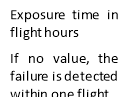
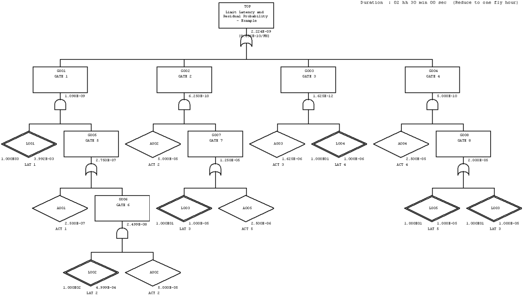
Figure A5-1: Fault Tree
|
# |
Probability (per flight hour) |
Event name |
Event description |
Failure rate (constant, unless noted) |
Exposure time |
Event probability (per flight) |
CS 25.1309(b)(5) Applicability/ compliance |
|
1 |
3.992E-10 |
A001 |
ACT 1 |
1.000E-07 |
2.5 h |
2.500E-07 |
Not compliant with the limit latency criterion [L001 probability is more frequent than 1.000E-03]. |
|
L001 |
LAT 1 |
4.000E-06 |
1 000.0 h |
3.992E-03 |
|||
|
2 |
2.000E-10 |
A002 |
ACT 2 |
2.000E-05 |
2.5 h |
5.000E-05 |
Not compliant with the residual probability criterion [A002 probability per flight hour (2.000E-05/FH) is more frequent than 1.000E-05/FH]. |
|
L003 |
LAT 3 |
1.000E-06 |
10.0 h |
1.000E-05 |
|||
|
3 |
1.000E-10 |
A004 |
ACT 4 |
1.000E-05 |
2.5 h |
2.500E-05 |
Not compliant with the residual probability criterion [while A004 probability per flight hour is equal to 1.000E-05/FH, the combined probability per flight hour of A004 and A002 (1.000E-05/FH + 2.000E-05/FH) is more frequent than 1.000E-05/FH. Note: Dual-order minimal cut sets #2 and #3 are grouped due to same event L003 appearing under G002 and G004. |
|
L003 |
LAT 3 |
1.000E-06 |
10.0 h |
1.000E-05 |
|||
|
4 |
1.000E-10 |
A004 |
ACT 4 |
1.000E-05 |
2.5 h |
2.500E-05 |
Compliant with both limit latency and residual probability criteria |
|
L005 |
LAT 5 |
1.000E-06 |
10.0 h |
1.000E-05 |
|||
|
5 |
5.000E-11 |
A002 |
ACT 2 |
2.000E-05 |
2.5 h |
5.000E-05 |
This dual-order minimal cut set does not contain any basic event being latent for more than one flight. |
|
A005 |
ACT 5 |
1.000E-06 |
2.5 h |
2.500E-06 |
|||
|
6 |
6.500E-13 |
A003 |
ACT 3 |
6.500E-07 |
2.5 h |
1.625E-06 |
Compliant with both limit latency and residual probability criteria |
|
L004 |
LAT 4 |
1.000E-07 |
10.0 h |
1.000E-06 |
|||
|
7 |
3.991E-11 |
A002 |
ACT 2 |
2.000E-05 |
2.5 h |
5.000E-05 |
This minimal cut set is more than a dual failure combination. |
|
L001 |
LAT 1 |
4.000E-06 |
1 000.0 h |
3.992E-03 |
|||
|
L002 |
LAT 2 |
5.000E-06 |
100.0 h |
4.999E-04 |
|||
|
Flight time = 2.5 hours P[LAT i] ~ FR * T |
|||||||
Table A5-1: Minimal Cut Sets
[Amdt 25/24]
[Amdt 25/27]
CS 25.1310 Power source capacity and distribution
ED Decision 2016/010/R
(See AMC 25.1310)
(a) Each installation whose functioning is required for type certification or by operating rules and that requires a power supply is an "essential load" on the power supply. The power sources and the system must be able to supply the following power loads in probable operating combinations and for probable durations (see AMC 25.1310(a)):
(1) Loads connected to the system with the system functioning normally.
(2) Essential loads, after failure of any one prime mover, power converter, or energy storage device.
(3) Essential loads after failure of -
(i) Any one engine on two-engine aeroplanes; and
(ii) Any two engines on three-or-more engine aeroplanes.
(4) Essential loads for which an alternate source of power is required, after any failure or malfunction in any one-power supply system, distribution system, or other utilisation system.
(b) In determining compliance with sub-paragraphs (a)(2) and (3) of this paragraph, the power loads may be assumed to be reduced under a monitoring procedure consistent with safety in the kinds of operation authorised. Loads not required in controlled flight need not be considered for the two-engine-inoperative condition on aeroplanes with three or more engines.
[Amdt 25/18]
AMC 25.1310(a) Power source capacity and distribution
ED Decision 2003/2/RM
When alternative or multiplication of systems and equipment is provided to meet the requirements of CS 25.1310(a), the segregation between circuits should be such as to minimise the risk of a single occurrence causing multiple failures of circuits or power supplies of the system concerned. For example, electrical cable bundles or groups of hydraulic pipes should be so segregated as to prevent damage to the main and alternative systems and power supplies.
CS 25.1315 Negative acceleration
ED Decision 2016/010/R
(See AMC 25.1315)
No hazardous malfunction may occur as a result of the aeroplane being operated at the negative accelerations within the flight envelopes prescribed in CS 25.333. This must be shown for the greatest duration expected for the acceleration.
[Amdt 25/18]
AMC 25.1315 Negative accelerations
ED Decision 2003/2/RM
1 Demonstration of compliance with CS 25.1315 should be made by analysis and/or ground tests, and should be supported by flight tests.
2 Analysis and/or Ground Tests. Appropriate analysis and/or ground tests should be made on components of essential fluid systems and such other components as are likely to be adversely affected by negative acceleration to demonstrate that they will not produce a hazardous malfunction.
3 Flight Tests
3.1 The aeroplane should be subjected to –
a. One continuous period of at least five seconds at less than zero g, and, separately,
b. A period containing at least two excursions to less than zero g in rapid succession, in which the total time at less than zero g is at least five seconds.
3.2 The tests should be made at the most critical condition from the fuel flow standpoint, e.g. with fuel flow corresponding to maximum continuous power and with the fuel representing a typical operational low fuel condition as for a missed approach.
CS 25.1316 Electrical and electronic system lightning protection
ED Decision 2015/019/R
(See AMC 20-136)
(a) Each electrical and electronic system that performs a function whose failure would prevent the continued safe flight and landing of the aeroplane must be designed and installed so that:
(1) the function is not adversely affected during and after the time the aeroplane is exposed to lightning; and
(2) the system automatically recovers normal operation of that function, in a timely manner, after the aeroplane is exposed to lightning, unless the system’s recovery conflicts with other operational or functional requirements of the system that would prevent continued safe flight and landing of the aeroplane.
(b) Each electrical and electronic system that performs a function whose failure would reduce the capability of the aeroplane or the ability of the flight crew to respond to an adverse operating condition must be designed and installed so that the function recovers normal operation in a timely manner after the aeroplane is exposed to lightning.
[Amdt 25/17]
CS 25.1317 High-Intensity Radiated Fields (HIRF) protection
ED Decision 2015/019/R
(See AMC 20-158)
(a) Each electrical and electronic system that performs a function whose failure would prevent the continued safe flight and landing of the aeroplane must be designed and installed so that:
(1) The function is not adversely affected during and after the time the aeroplane is exposed to HIRF environment I, as described in Appendix R;
(2) The system automatically recovers normal operation of that function, in a timely manner, after the aeroplane is exposed to HIRF environment I, as described in Appendix R, unless the system’s recovery conflicts with other operational or functional requirements of the system that would prevent continued safe flight and landing of the aeroplane; and
(3) The system is not adversely affected during and after the time the aeroplane is exposed to HIRF environment II, as described in Appendix R.
(b) Each electrical and electronic system that performs a function whose failure would significantly reduce the capability of the aeroplane or the ability of the flight crew to respond to an adverse operating condition must be designed and installed so that the system is not adversely affected when the equipment providing the function is exposed to equipment HIRF test level 1 or 2, as described in Appendix R.
(c) Each electrical and electronic system that performs a function whose failure would reduce the capability of the aeroplane or the ability of the flight crew to respond to an adverse operating condition must be designed and installed so that the system is not adversely affected when the equipment providing the function is exposed to equipment HIRF test level 3, as described in Appendix R.
[Amdt 25/17]
CS 25.1319 Equipment, systems and network information protection
ED Decision 2020/006/R
(a) Aeroplane equipment, systems and networks, considered separately and in relation to other systems, must be protected from intentional unauthorised electronic interactions (IUEIs) that may result in adverse effects on the safety of the aeroplane. Protection must be ensured by showing that the security risks have been identified, assessed and mitigated as necessary.
(b) When required by paragraph (a), the applicant must make procedures and Instructions for Continued Airworthiness (ICA) available that ensure that the security protections of the aeroplane’s equipment, systems and networks are maintained.
[Amdt 25/25]
AMC to CS 25.1319 Equipment, systems and network information security protection
ED Decision 2020/006/R
In showing compliance with CS 25.1319, the applicant may consider AMC 20-42, which provides acceptable means, guidance and methods to perform security risk assessments and mitigation for aircraft information systems.
The term ‘adverse effects on the safety of the aeroplane’ limits the scope of this provision to security breaches that impact on the safety and airworthiness of the aeroplane and its operation, rather than security breaches that may impact on the systems that have no safety effect on the aeroplane. For example, while the manufacturer and the air operator may have real concerns about protecting a device that is used to process passenger credit cards and securing passenger information, EASA does not regard this as being subject to review and approval as part of the certification of the system, but instead as something that the air operator or manufacturer would address as part of their business practices and responsibilities to the customer.
The term ‘mitigated as necessary’ clarifies that the applicant has the discretion to establish appropriate means of mitigation against security risks.
The term ‘procedures and Instructions for Continued Airworthiness (ICA)’ clarifies that, while the ICA may be one mechanism for providing the necessary instructions to maintain airworthiness, the security protections may go beyond traditional ICA material, and also include other procedures provided to the air operator. This aligns with the existing practices among those applicants for which special conditions (SCs) have been issued to address the protection of the aircraft information systems’ security.
[Amdt 25/25]