
CS 25.1321 Arrangement and visibility
ED Decision 2003/2/RM
(a) Each flight, navigation, and powerplant instrument for use by any pilot must be plainly visible to him from his station with the minimum practicable deviation from his normal position and line of vision when he is looking forward along the flight path.
(b) The flight instruments required by CS 25.1303 must be grouped on the instrument panel and centred as nearly as practicable about the vertical plane of the pilot’s forward vision. In addition –
(1) The instrument that most effectively indicates attitude must be on the panel in the top centre position;
(2) The instrument that most effectively indicates airspeed must be adjacent to and directly to the left of the instrument in the top centre position;
(3) The instrument that most effectively indicates altitude must be adjacent to and directly to the right of the instrument in the top centre position; and
(4) The instrument that most effectively indicates direction of flight must be adjacent to and directly below the instrument in the top centre position.
(c) Required powerplant instruments must be closely grouped on the instrument panel. In addition –
(1) The location of identical powerplant instruments for the engines must prevent confusion as to which engine each instrument relates; and
(2) Powerplant instruments vital to the safe operation of the aeroplane must be plainly visible to the appropriate crewmembers.
(d) Instrument panel vibration may not damage or impair the accuracy of any instrument.
(e) If a visual indicator is provided to indicate malfunction of an instrument, it must be effective under all probable cockpit lighting conditions.
CS 25.1322 Flight Crew Alerting
ED Decision 2011/004/R
(See AMC 25.1322)
(a) Flight crew alerts must:
(1) provide the flight crew with the information needed to:
(i) identify non-normal operation or aeroplane system conditions, and
(ii) determine the appropriate actions, if any;
(2) be readily and easily detectable and intelligible by the flight crew under all foreseeable operating conditions, including conditions where multiple alerts are provided;
(3) be removed when the alerting condition no longer exists.
(b) Alerts must conform to the following prioritisation hierarchy based on the urgency of flight crew awareness and response:
(1) Warning: For conditions that require immediate flight crew awareness and immediate flight crew response.
(2) Caution: For conditions that require immediate flight crew awareness and subsequent flight crew response.
(3) Advisory: For conditions that require flight crew awareness and may require subsequent flight crew response.
(c) Warning and Caution alerts must:
(1) be prioritised within each category, when necessary;
(2) provide timely attention-getting cues through at least two different senses by a combination of aural, visual, or tactile indications;
(3) permit each occurrence of the attention-getting cues required by sub-paragraph (c)(2) to be acknowledged and suppressed, unless they are required to be continuous.
(d) The alert function must be designed to minimise the effects of false and nuisance alerts. In particular, it must be designed to:
(1) prevent the presentation of an alert when it is inappropriate or unnecessary;
(2) provide a means to suppress an attention-getting component of an alert caused by a failure of the alerting function that interferes with the flight crew’s ability to safely operate the aeroplane. This means must not be readily available to the flight crew so that it could be operated inadvertently or by habitual reflexive action. When an alert is suppressed, there must be a clear and unmistakable annunciation to the flight crew that the alert has been suppressed.
(e) Visual alert indications must:
(1) conform to the following colour convention:
(i) Red for Warning alert indications.
(ii) Amber or yellow for Caution alert indications.
(iii) Any colour except red or green for Advisory alert indications.
(2) use visual coding techniques, together with other alerting function elements on the flight deck, to distinguish between Warning, Caution and Advisory alert indications, if they are presented on monochromatic displays that are incapable of conforming to the colour convention in paragraph (e)(1).
(f) Use of the colours red, amber and yellow on the flight deck for functions other than flight crew alerting must be limited and must not adversely affect flight crew alerting.
[Amdt 25/11]
ED Decision 2011/004/R
1. Purpose
2. Applicability
3. Related Examples, Regulations, Documents, and Definitions
4. Background
5. Designing a Flight crew Alerting System
a. General
b. Flight crew Alerting Philosophy
c. Design Considerations
6. Alert Functional Elements
a. Warning Alerts
b. Time-Critical Warning Alerts
c. Master Visual and Aural Alerts
d. Caution Alerts
e. Advisory Alerts
7. Alerting System Reliability and Integrity
8. Managing Alerts
a. Rules and General Guidelines
b. Multiple Aural Alerts
c. Multiple Visual Alerts
d. Alert Inhibits
9. Clearing and Recalling Visual Alert Messages
10. Interface or Integration with Other Systems
11. Colour Standardisation
12. Minimising the Effects of False and Nuisance Alerts
13. Showing Compliance for Approval of a Flight crew Alerting System
14. Integrating Flight crew Alerting System Elements into the Existing Fleet
a. General
b. Visual Alerts
c. Aural Alerts
d. Tactile Alerts
15. Alerts for Head-Up Displays (HUDs)
List of Appendices
Appendix 1 Examples for Including Visual System Elements in an Alerting System
Appendix 2 Examples for Including Aural System Elements in an Alerting System
Appendix 3 Regulations
Appendix 4 Related Documents
Appendix 5 Definitions
1. Purpose
This AMC provides an acceptable means of compliance and guidance material for showing compliance with certain requirements of CS-25, for the design approval of flight crew alerting functions. This AMC addresses the type of alert function elements that should be considered (including visual, aural, and tactile or haptic elements), alert management, interface or integration of alerts with other systems, and colour standardisation. The appendices to this AMC also provide examples for including visual and aural system elements in an alerting system.
a. This AMC is applicable to aeroplane manufacturers, modifiers, avionics manufacturers, EASA type-certification engineers, human factor specialists and test pilots.
b. This AMC is applicable to new aeroplanes. It may also be applicable to modified aeroplanes and to integrating flight crew alerting system elements into existing aeroplanes. It applies to individual aircraft systems that provide flight crew alerting functions that may or may not be integrated with a central alerting system, as well as to systems whose primary function is alerting, such as a central alerting system.
3. Related Examples, Certification Specifications, Documents, and Definitions
Appendix 1 of this AMC provides examples for including visual system elements in an alerting system. Appendix 2 of this AMC provides examples for including aural system elements in an alerting system. Appendix 3 of this AMC lists the airworthiness and operational certification specifications related to this AMC. Appendix 4 of this AMC lists related AMCs and other documents that are provided for information purposes and are not necessarily directly referenced in this AMC. Appendix 5 provides definitions written to support the content of this AMC and its associated certification specification.
a. While the flight crew is ultimately responsible for the operation of the aeroplane, the provision of an alerting system that aids the flight crew in identifying non-normal operational or aeroplane system conditions and in responding in an appropriate and timely manner is an essential feature of every flight deck design. In the past, aeroplanes were designed with discrete lights for the alerting function. Now the alerting function can be integrated with other systems, including electronic display systems, tactile warning systems, and aural warning or tone generating systems.
b. CS-25 often provides references to an alert, such as a warning, to provide awareness of a non-normal condition. Many of these certification specifications were written without recognition of a consistent flight deck alerting philosophy, and may use the term “warning” and “alert” in a generic sense. This AMC does not intend to conflict with or replace the intent of those certification specifications. The intent here is to standardise flight crew alerting terminology used and to provide a means for applicants to show compliance with those certification specifications.
5. Designing a Flight crew Alerting System
a. General. The purpose of flight crew alerts on aeroplanes is to attract the attention of the flight crew, to inform them of specific non-normal aeroplane system conditions or certain non-normal operational events that require their awareness, and, in modern alerting systems, to advise them of possible actions to address these conditions. The ability of an alert to accomplish its intent depends on the design of the complete alert function. This includes the sensor and the sensed condition required to trigger an alert, how that information is subsequently processed, including the level of urgency and priority assigned, and the choice of alert presentation elements to express the assigned level of urgency. Conditions that do not require flight crew awareness should not generate an alert.
b. Flight crew Alerting Philosophy. When developing a flight crew alerting system, use a consistent philosophy for alerting conditions, urgency and prioritisation, and presentation.
(1) Alerting conditions. Establish how aeroplane system conditions or operational events that require an alert (for example, engine overheating, windshear, etc.), will be determined.
(2) Urgency and Prioritisation. Establish how the level of urgency (Warning, Caution and Advisory) associated with each alerting condition will be prioritised and classified to meet the requirements listed in CS 25.1322(b) and CS 25.1322(c)(1). If an alert’s urgency and prioritisation is context sensitive, state what information should be considered (for example, the priority associated with different alerting conditions may vary depending on the state of the aeroplane, phase of flight, system configuration, etc.).
(3) Presentation. Establish a consistent alert presentation scheme (for example, location of the alert on the flight deck, alert combinations [aural, visual, tactile], information presented in the Alert message, and colour and graphical coding standardisation). Also, determine the format in which that alert will be presented (for example, structure and timing of Alert messages) to support the alerting function’s purpose.
c. Design Considerations. Consider the following concepts and elements when designing an alerting system:
(1) Only non-normal aeroplane system conditions and operational events that require flight crew awareness to support flight crew decision making and facilitate the appropriate flight crew response should cause an alert. However, conditions that require an alert depend on the specific system and aeroplane design, and overall flight-deck philosophy. For example, the failure of a single sensor in a multi-sensor system may not necessarily result in an alert condition that requires pilot awareness. However, for a single sensor system, such a failure should result in an alert condition that provides the flight crew with the information needed to assure continued safe flight and landing.
(2) All alerts presented to the flight crew, (for example, light, aural annunciation, engine-indication-and-crew-alerting system (EICAS) message, master caution) must provide the flight crew with the information needed to identify the non-normal operational or aeroplane system condition and determine the corrective action, if any (CS 25.1322(a)(1)). Appropriate flight crew corrective actions are normally defined by aeroplane procedures (for example, in checklists) and are part of a flight crew training curriculum or considered basic airmanship.
(3) Implement a consistent flight crew alerting philosophy as described in paragraph 5.b of this AMC.
(4) Include the appropriate combination of alerting system presentation elements, which typically include:
(a) Master visual alerts
(b) Visual alert information (includes Failure flag indications)
(c) Master aural alerts
(d) Voice information
(e) Unique tones (unique sounds)
(f) Tactile or haptic information
(5) Use logic-based integrated alerting systems to ensure that alerting system elements are synchronised and provide the proper alert presentation format for each urgency level. For example, the onset of the Master visual alert should normally occur simultaneously with the onset of the Master aural alert.
(6) Present the alerts according to the urgency and prioritisation philosophy outlined in paragraph 5.b and described in detail in paragraph 8.a of this AMC.
(7) Visual alerts must conform to the colour convention of CS 25.1322(e). Paragraph 11 of this AMC provides guidance on the colour convention.
(8) If using aural alerts with multiple meanings, a corresponding visual, tactile, or haptic alert should be provided to resolve any potential uncertainty relating to the aural alert and clearly identify the specific alert condition.
6. Alert Functional Elements. The functional elements used in the alerting and information functions for Warning and Caution alerts must provide timely attention-getting cues, resulting in immediate flight crew awareness, through at least two different senses (CS 25.1322(c)(2)). Functional elements used for Advisory alerts do not require immediate flight crew awareness and are normally provided through a single sense.
a. Warning Alerts. Several alert functional element combinations are used to comply with CS 25.1322(c)(2) (two-senses requirement). The typical alert-element combinations for Warning alerts (not including Time-critical warning alerts) are shown below.
(1) Master visual alert, Visual alert information, and Master aural alert.
(2) Master visual alert, Visual alert information, and Voice information or Unique tone.
Note 1: Voice information may be preceded by a Master aural alert.
Note 2: A tactile alert may be combined with a visual or aural alert to meet the CS 25.1322 requirement for a combination of two senses.
b. Time-Critical Warning Alerts. Some Warnings may be so time-critical for the safe operation of the aeroplane that general alerts such as a Master visual alert and a Master aural alert may not provide the flight crew with immediate awareness of the specific alerting condition that is commensurate with the level of urgency of flight crew response necessary. In such cases, Warning elements dedicated to specific alerting conditions should be provided that give the flight crew immediate awareness without further reference to other flight deck indications. Examples of such Time-critical warnings include reactive windshear and ground proximity. The alerting elements for Time-critical warnings should include:
— Unique Voice information or Unique tone, or both, for each alerting condition, and
— Unique Visual alert information in each pilot’s primary field of view for each alerting condition.
Note: A unique tactile alert sensed by each pilot can also meet the CS 25.1322(c)(2) requirement for one of the two senses.
c. Master Visual and Aural Alerts. A Master visual alert and a Master aural alert may not be warranted if other visual and aural means provide more timely attention-getting characteristics. If a Master visual alert and/or a Master aural alert are used, they should aid in the overall attention-getting characteristics and the desired flight crew response and not distract the flight crew from the time‑critical condition. For example, unique Visual alert information presented in each pilot’s primary field of view is acceptable in place of a Master visual alert if it provides immediate awareness and sufficient attention-getting characteristics. However, an aural alert, such as an aural command to “pull up,” or another sensory cue, would still be required to meet CS 25.1322(c)(2).
d. Caution Alerts
(1) The alert elements used for Caution are typically identical to those used for Warnings, as both require immediate flight crew awareness.
(2) Some Caution alerts are related to conditions that are precursors to potential Time‑critical warning conditions. In these cases, the alerting system elements associated with the Caution should be consistent with the elements for related Time-critical warnings (described in paragraph 6.b of this AMC). For example, reactive windshear warnings, ground-proximity warnings, and Caution alerts can develop into Time-critical warning alerts.
(1) The alerting and informing functional elements for advisories must meet the applicable requirements of CS 25.1322 and should include Visual alert information. Advisory information should be located in an area where the flight crew is expected to periodically scan for information.
(2) Advisory information does not require immediate flight crew awareness. Therefore, it does not require alerting that uses a combination of two senses. In addition, a Master visual alert or Master aural alert is not typically used since immediate flight crew awareness is not needed.
(3) Aural or visual information such as maintenance messages, information messages, and other status messages associated with conditions that do not require an alert may be presented to the flight crew, but the presentation of this information should not interfere with the alerting function or its use.
7. Alerting System Reliability and Integrity
a. The alerting system, considered alone and in relation to other systems, should meet the safety objectives of the relevant system safety standards (for example, CS 25.901(b)(2), CS 25.901(c), and CS 25.1309(b)). The reliability and integrity of the alerting system should be commensurate with the safety objectives associated with the system function, or aeroplane function, for which the alert is provided.
b. When applying the CS 25.1309(b) system safety analysis process to a particular system or function that has an associated flight crew alert, assess both the failure of the system or function and a failure of its associated alert (CS 25.1309(d)(4)). This should include assessing the effect of a single (common or cascading mode) failure that could cause the failure of a system function and the failure of any associated alerting function. A failure is defined as: “An occurrence that affects the operation of a component, part, or element such that it can no longer function as intended. This includes both loss of function and malfunction.” Therefore, in conducting the safety analysis, both loss of functions and malfunctions should be considered.
c. Since the flight crew alerting function is often integrated with, or is common to, other systems, the impact of a failure or error in the alerting system must be assessed separately and in relation to other systems as required by CS 25.1309(b). The cascading effects of a failure or error in the alerting function, and in the interfacing system, should be analysed. Give special consideration to avoid alerting that, through misinterpretation, could increase the hazard to the aeroplane (CS 25.1309(c)). For example, there should not be a foreseeable way that a fire warning for one engine could be misinterpreted as a fire on a different engine.
d. Assess the reliability of the alerting system by evaluating the reduction in the safety margin if the alerting system fails. The evaluation should address:
(1) Loss of the complete alerting function.
(2) A malfunction.
(3) Loss or malfunction of one alert in combination with the system condition for which the alert is necessary.
e. The integrity of the alerting system should be examined because it affects the flight crew’s trust and response when assessing an alert. Since the individual assessment of a False or Nuisance alert for a given system may lead to a specific consequence, the impact of frequent False or Nuisance alerts increases the flight crew’s workload, reduces the flight crew’s confidence in the alerting system, and affects their reaction in case of a real alert. For example, if False or Nuisance alerts are presented the flight crew may ignore a real alert when it is presented.
8. Managing Alerts. Prioritise alerts so that the most urgent alert is presented first to the flight crew.
a. Rules and General Guidelines
(1) All flight deck alerts must be prioritised into Warning, Caution, and Advisory categories (CS 25.1322(b)).
(2) To meet their intended function(s), alerts must be prioritised based upon urgency of flight crew awareness and urgency of flight crew response (§ 25.1301(a)). Normally, this means Time-critical warnings are first, other Warnings are second, Cautions are third, and Advisories are last (CS 25.1322(b)).
(3) Depending on the phase of flight, there may be a need to re-categorise certain alerts from a lower urgency level to a higher urgency level. Furthermore, prioritisation within alert categories may be necessary if the presentation of multiple alerts simultaneously would cause flight crew confusion, or the sequencing of flight crew response is important. For example, when near threatening terrain, Time-critical warnings must be prioritised before other Warnings within the Warning alert category (CS 25.1322(c)(1)). JAA TGL-12 (TAWS), also identifies situations where prioritisation within alert categories is necessary.
(4) The prioritisation scheme within each alert category, as well as the rationale, should be documented and evaluated, by following the guidance in paragraph 13, The Showing of Compliance, of this AMC.
(5) Documentation should include the results of analyses and tests that show that any delayed or inhibited alerts do not adversely impact safety.
(1) Aural alerts should be prioritised so that only one aural alert is presented at a time. If more than one aural alert needs to be presented at a time, each alert must be clearly distinguishable and intelligible by the flight crew (CS 25.1322(a)(2)).
(2) When aural alerts are provided, an active aural alert should finish before another aural alert begins. However, active aural alerts must be interrupted by alerts from higher urgency levels if the delay to annunciate the higher-priority alert impacts the timely response of the flight crew (CS 25.1301(a)). If the condition that triggered the interrupted alert is still active, that alert may be repeated once the higher-urgency alert is completed. If more than one aural alert requires immediate awareness and the interrupted alert(s) affects the safe operation of the aeroplane, an effective alternative means of presenting the alert to the flight crew must be provided to meet the requirements of CS 25.1322(a)(1) and (a)(2).
(1) Since two or more visual alerts can occur at the same time, applicants must show that each alert and its relative priority are readily and easily detectable and intelligible by the flight crew (CS 25.1322(a)(2)).
(2) When multiple alerts exist in a specific category (for example, multiple Warning alerts or multiple Caution alerts), a means for the flight crew to determine the most recent or most urgent alert must be provided (CS 25.1322(c)(1)). For example, the most recent or highest priority alert may be listed at the top of its own category. If the alert is time-critical and shares a dedicated display region it must have the highest alerting priority to satisfy its intended function (CS 25.1301(a)).
(3) Displays must either conform to the alert colour convention or, in the case of certain monochromatic displays not capable of conforming to the colour conventions, use other visual coding techniques per CS 25.1322(e). This is necessary so the flight crew can easily distinguish the alert urgency under all foreseeable operating conditions, including conditions where multiple alerts are provided (CS 25.1322(a)(2)).
(1) Alert inhibit functions must be designed to prevent the presentation of an alert that is inappropriate or unnecessary for a particular phase of operation (CS 25.1322(d)(1)). Alert inhibits can also be used to manage the prioritisation of multiple alert conditions. Inhibiting an alert is not the same as clearing or suppressing an alert that is already displayed.
(2) Alert inhibits should be used in the following conditions:
(a) When an alert could cause a hazard if the flight crew was distracted by or responded to the alert.
(b) When the alert provides unnecessary information or awareness of aeroplane conditions.
(c) When a number of consequential alerts may be combined into a single higher‑level alert.
(3) Alerts can be inhibited automatically by the alerting system or manually by the flight crew.
(4) For operational conditions not recognised by the alerting system, provide a means for the flight crew to inhibit a potential alert that would be expected to occur as the result of the specific operation (for example, preventing a landing configuration alert for a different landing flap setting). For as long as the inhibit exists, there should be a clear and unmistakable indication that the flight crew manually inhibited that alert.
9. Clearing and Recalling Alert Messages. Clearing Alert messages from the current Warning, Caution, and Advisory display allows the flight crew to remove a potential source of distraction and makes it easier for the flight crew to detect subsequent alerts.
a. The following guidance should be applied for clearing and recalling or storing Alert messages:
(1) If a message can be cleared and the condition still exists, the system should provide the ability to recall any cleared Alert message that has been acknowledged.
(2) Either through a positive indication on the display or through normal flight crew procedures, a means should be provided to identify if Alert messages are stored (or otherwise not in view).
b. The Alert message must be removed from the display when the condition no longer exists (CS 25.1322(a)(3)).
10. Interface or Integration with Other Systems (Checklist, Synoptics, Switches, Discrete lamps).
a. The colour of all visual alerting annunciations and indications must conform to the colour convention in CS 25.1322(e). Use consistent wording, position, colour and other shared attributes (for example, graphic coding) for all alerting annunciations and indications.
b. Information displayed in the flight deck associated with the alert condition must facilitate the flight crew’s ability to identify the alert (CS 25.1322(a)(1)(i)) and determine the appropriate actions, if any (CS 25.1322(1)(ii)).
c. Information conveyed by the alerting system should lead the flight crew to the correct checklist procedure to facilitate the appropriate flight crew action. Some flight deck alerting systems automatically display the correct checklist procedure or synoptic display when an alert is presented. Some alerts do not display an associated checklist procedure because the correct flight crew action is covered by training or basic airmanship (for example, autopilot disconnect and Time-critical warnings). In all cases, the aeroplane or system certification test programme should verify that the alerts provide or direct the flight crew to the correct procedures.
d. If multiple checklists can be displayed (for example, multiple checklists associated with multiple alerts), the flight crew should be able to readily and easily choose the appropriate checklist and action for each alert. For example, the flight crew must be able to easily distinguish which checklist has priority regarding what the flight crew needs to do first to determine the appropriate actions, if any (CS 25.1322(a)(1)(ii)).
11. Colour Standardisation. The objective of colour standardisation is to maintain the effectiveness of visual alerts by enabling the flight crew to readily distinguish between alert categories.
a. Visual alert indications must conform to the following colour convention (CS 25.1322(e)):
(1) Red for Warning alert indications.
(2) Amber or yellow for Caution alert indications.
(3) Any colour except red or green for Advisory alert indications.
Note: Green is usually used to indicate “normal” conditions; therefore, it is not an appropriate colour for an Advisory alert. An Advisory alert is used to indicate a “non-normal” condition.
b. A separate and distinct colour should be used to distinguish between Caution and Advisory alerts. If a distinctive colour is not used to distinguish between Caution and Advisory alerts, other distinctive coding techniques must be used to meet the general requirements of CS 25.1322(a)(2) so that the flight crew can readily and easily detect the difference between Caution and Advisory alerts.
c. The colour displayed for the Warning Master visual alert must be the same colour used for the associated Warning alerts and the colour displayed for the Caution Master visual alert must be the same colour used for the associated Caution alerts (CS 25.1322(e)(1)).
d. The colours red, amber, and yellow must be used consistently (CS 25.1322 (e)(1)). This includes alert colour consistency among propulsion, flight, navigation, and other displays and indications used on the flight deck.
e. For monochromatic displays that are not capable of conforming to the colour convention required by CS 25.1322(e)(2), use display coding techniques (for example, shape, size, and position) so the flight crew can clearly distinguish between Warning, Caution, and Advisory alerts. This requirement is similar to using selected colour coding on multicolour displays that allows the flight crew to easily distinguish between Warning, Caution, and Advisory alerts (CS 25.1322(e)). These coding techniques must also meet the general alerting requirement in CS 25.1322(a)(2) so the alerts are readily and easily detectable and intelligible by the flight crew under all foreseeable operating conditions, including conditions where multiple alerts are provided. The wide use of monochromatic displays on the flight deck with flight crew alerting is normally discouraged, except when an increased safety benefit is demonstrated, for example, a HUD used as a primary flight display.
f. CS 25.1322(f) requires that the use of the colours red, amber and yellow on the flight deck for functions other than flight crew alerting must be limited and must not adversely affect flight crew alerting. Consistent use and standardisation for red, amber, and yellow is required to retain the effectiveness of flight crew alerts. It is important that the flight crew does not become desensitised to the meaning and importance of colour coding for alerts, which could increase the flight crew’s processing time, add to their workload, and increase the potential for flight crew confusion or errors.
g. Where red, amber and yellow are proposed for non-flight crew alerting functions, substantiate that there is an operational need to use these colours to provide safety related awareness information. Examples of acceptable uses of red, amber, or yellow for non-alerting functions include:
— Weather radar display (for areas of severe/hazardous weather conditions that should be avoided);
— TAWS terrain display (for local terrain relative to the current altitude).
12. Minimising the Effects of False and Nuisance Alerts. As much as possible, the alerting functions or system should be designed to avoid False alerts and Nuisance alerts, while providing reliable alerts to the flight crew when needed. The effects of Nuisance and False alerts distract the flight crew, increase their potential for errors, and increase their workload. CS 25.1322(d) requires that an alert function be designed to minimise the effects of False and Nuisance alerts. Specifically, a flight crew alerting system must be designed to:
a. Prevent the presentation of an alert when it is inappropriate or unnecessary.
b. Provide a means to suppress an attention-getting component of an alert caused by a failure of the alerting system that interferes with the flight crew’s ability to safely operate the aeroplane. This means must not be readily available to the flight crew so that it can be operated inadvertently or by habitual, reflexive action.
c. Permit each occurrence of attention-getting cues for Warning and Caution alerts to be acknowledged and then suppressed, unless the alert is required to be continuous (CS 25.1322(c)). Reaching forward and pressing a switch light is a common, acceptable means of suppressing the attention-getting components of an aural alert, a flashing master warning, or a caution light.
d. Remove the presentation of the alert when the condition no longer exists (CS 25.1322(a)(3)).
e. Pulling circuit breakers is not an acceptable primary means for the flight crew to suppress a False alert.
a. Certification evaluations may be different from project to project because of the complexity, degree of integration, and specifics of the proposed alerting function or system. We recommend developing a plan to establish how compliance with the rules will be shown and to document how issues will be identified, tracked, and resolved throughout the life cycle of the type investigation programme. We also recommend including the Agency early in the developmental process to discuss the acceptability of any proposed flight deck design and alerting philosophy and the conditions that should be alerted to the flight crew. Typically, the certification programme is used for this purpose. For addressing human factors and pilot interface issues, in addition to the guidance in this AMC, compliance with CS 25.1302 and associated AMC must be shown.
b. When following the guidance in this AMC, document any divergence from this AMC, and provide the rationale for decisions regarding novel or unusual features used in the design of the alerting system. This will facilitate the certification evaluation because it will enable the Agency to focus on areas where the proposed system diverges from the AMC and has new or novel features.
c. In accordance with the certification programme, provide an evaluation of the alerting system. In this case an evaluation is an assessment of the alerting system conducted by an applicant, who then provides a report of the results to the Agency. Evaluations are different from tests because the representation of the alerting system does not necessarily conform to the final documentation and the Agency may or may not be present. Evaluations by the applicant may contribute to a finding of compliance, but they do not constitute a complete showing of compliance by themselves.
(1) The evaluation should include assessments of acceptable performance of the intended functions, including the human-machine interface, and acceptability of alerting system failure scenarios. The scenarios should reflect the expected operational use of the system. Specific aspects that should be included during the evaluation(s) are:
(a) Visual, aural, and tactile/haptic aspects of the alert(s).
(b) Effectiveness of meeting intended function from the human/machine integration, including workload, the potential for flight crew errors, and confusion.
(c) Normal and emergency inhibition and suppression logic and accessibility of related controls.
(d) Proper integration with other systems, including labelling. This may require testing each particular alert and verifying that the appropriate procedures are provided.
(e) Acceptability of operation during failure modes per CS 25.1309.
(f) Compatibility with other displays and controls, including multiple Warnings.
(g) Ensuring that the alerting system by itself does not issue Nuisance alerts or interfere with other systems.
(h) Inhibiting alerts for specific phases of flight (for example, take-off and landing) and for specific aeroplane configurations (for example, abnormal flaps and gear).
(2) The validation of the performance and integrity aspects will typically be accomplished by a combination of the following methods:
— Analysis
— Laboratory test
— Simulation
— Flight test
(3) Evaluate the alerts in isolation and combination throughout the appropriate phases of flight and manoeuvres, as well as representative environmental and operational conditions. The alerting function as a whole needs to be evaluated in a representative flight deck environment. Representative simulators can be used to accomplish the evaluation of some human factors and workload studies. The level and fidelity of the simulator should be commensurate with the certification credit being sought. The simulator should represent the flight deck configuration and be validated by the Agency. The assessment of the alerts may be conducted in a laboratory, simulator, or the actual aeroplane. Certain elements of the alerting system may have to be validated in the actual aeroplane. The evaluation should be conducted by a representative population of pilots with various backgrounds and expertise.
(4) Evaluations should also verify the chromaticity (red looks red and amber looks amber) and discriminability (colours can be distinguished from each other) of the colours being used, under the expected lighting levels. Evaluations may also be useful to verify the discriminability of graphic coding used on monochromatic displays. These evaluations can be affected by the specific display technology being used, so a final evaluation with production representative hardware is sometimes needed.
14. Integrating Flight crew Alerting System Elements into the Existing Fleet
(1) This material provides recommendations to applicants on how to retrofit existing aeroplanes so they comply with CS 25.1322 without major modifications to the current flight crew alerting system.
(2) System upgrades to existing aeroplanes should be compatible with the original aeroplane’s flight crew alerting philosophy. The existing alerting system might not be able to facilitate the integration of additional systems and associated alerts due to limitations in the system inputs, incompatible technologies between the aeroplane and the system being added, or economic considerations.
(a) We discourage incorporating a new additional master visual function into the flight crew alerting system. If it is not feasible to include additional systems and associated alerts in the existing master visual function, an additional master visual function may be installed, provided that it does not delay the flight crew’s response time for recognising and responding to an alert.
(b) Where possible, new alerts should be integrated into the existing flight crew alerting system. If these alerts cannot be integrated, individual annunciators or an additional alerting display system may be added.
(c) Not all alerts associated with failure flags need to be integrated into the central alerting system. However, for those alerts requiring immediate flight crew awareness, the alert needs to meet the attention-getting requirements of CS 25.1322(c)(2) as well as the other requirements in CS 25.1322. Thus, a Master visual alert or Master aural alert may not be initiated, but an attention-getting aural or tactile indication must still accompany an attention-getting visual failure flag to meet the attention-getting requirement of CS 25.1322(a)(1), which requires attention-getting cues through at least two different senses for Warning and Caution alerts.
b. Visual Alerts. Following the guidance in paragraphs 5 and 6 of this AMC, determine whether or not the added system features will require activation of an aeroplane Master visual alert.
(1) Using the guidance in this AMC, determine if an added system will require activating an aural alert.
(2) The new aural alert should be integrated into the existing aural alerting system and functions. If this is not possible, a separate aural alerting system may be installed, provided that a prioritisation scheme between existing aural alerts and the new aural alerts is developed so that each alert is recognised and can be acted upon in the time frame appropriate for the alerting situation. This may require a demonstration of any likely combination of simultaneous alerts. After the new and existing alerts have been merged, follow the guidance in this AMC for determining how to prioritise the alerts.
(1) Using the guidance in this AMC, determine if an added system will require activating a tactile alert.
(2) If possible, incorporate the new tactile alert into the existing alerting system. If this is not possible, a separate tactile alerting system may be installed, provided that the following elements are included:
(a) A prioritisation scheme between existing tactile alerts and the new tactile alerts should be developed so that each alert is recognised and can be acted upon in the time frame appropriate for the alerting situation. After the new and existing alerts have been merged, follow the guidance in this AMC for determining how to prioritise the alerts.
(b) A means to ensure that an individual alert can be understood and acted upon. This may require a demonstration of any likely combination of simultaneous alerts.
15. Alerts for Head-Up Displays (HUDs)
a. HUDs have visual characteristics that merit special considerations for alerting. First, most HUDs are single-colour (monochromatic) displays and are not capable of using different colours, such as red, amber and yellow to signify alert information. Second, HUDs are located in the pilot’s forward field of view, separated from the instrument panel, and focused at optical infinity. As a result, many visual indications on the instrument panel are not visible to the pilot while viewing the HUD, and the timely detection of visual alerts displayed on the instrument panel may not be possible. Therefore, even though HUDs are not intended to be classified as integrated caution and warning systems, they do need to display certain alerts, such as Time‑critical warnings, to perform their role as a primary flight display (PFD). Monochromatic HUDs are not required to use red and amber to signify Warning and Caution alerts, but do need to provide the equivalent alerting functionality (for example, attention-getting, clearly understandable, not confusing) as current head-down display (HDD) PFDs (CS 25.1322(e)).
b. Alerting functions presented in the HUD should not adversely affect the flight crew’s use of the HUD by obstructing the flight crew’s outside view through the HUD.
c. Time-critical warnings that are displayed on the HDD PFD also need to be presented on the HUD to ensure equivalent timely pilot awareness and response (for example, ACAS II, windshear, and ground-proximity warning annunciations) (CS 25.1301(a)). Otherwise, the physical separation of the HUD and head-down fields of view and the difference in accommodation (that is, focal distance) would hinder timely pilot awareness of visual alerts displayed head-down.
d. While a pilot is using the HUD, if the master alerting indications are not visible or attention-getting, the HUD needs to display alerts that provide the pilot with timely notification of Caution conditions, Warning conditions, or both.
e. CS 25.1322(e) requires visual alert indications on monochromatic displays to use coding techniques so the flight crew can clearly distinguish between Warning, Caution, and Advisory alerts. Since monochromatic HUDs are incapable of using colours to distinguish among Warning, Caution, and Advisory information, other visual display features (coding techniques) are necessary, such as shape, location, texture, along with the appropriate use of attention-getting properties such as flashing, outline boxes, brightness, and size. The use of these visual display features should be consistent within the set of flight deck displays, so that the intended meaning is clearly and unmistakably conveyed. For example, Time-critical warnings might be boldly displayed in a particular central location on the HUD, while less critical alerts, if needed, would be displayed in a different manner.
f. For multi-colour HUDs, the display of Warning and Caution alerts should be consistent with HDD PFD presentations.
g. Pilot flying and pilot monitoring roles should account for the use of HUDs to ensure timely awareness of certain alerts, especially because of field of view factors.
(1) For single-HUD installations, when the pilot flying is using the HUD, the other pilot should be responsible for monitoring the head-down instruments and alerting systems for system failures, modes, and functions that are not displayed on the HUDs.
(2) For dual-HUD installations there needs to be greater reliance on master alerting indications that are capable of directing each pilot’s attention to non-HUD alerts when both HUDs are in use. If master alerting indications do not provide sufficient attention to each pilot while using the HUD, then each HUD should provide annunciations that direct the pilot’s attention to HDDs. The types of information that should trigger the HUD master alerting display are any Cautions or Warnings not already duplicated on the HUD from the HDD.
[Amdt 25/11]
Appendix 1 – Examples for Including Visual System Elements in an Alerting System
ED Decision 2015/019/R
This appendix includes detailed guidance and examples to help applicants with a means of compliance and design for visual system elements in an alerting system. They are based on the Agency’s experience with existing and proposed alerting systems that comply with CS 25.1322. The extent to which this guidance and these examples are applied to a specific type investigation programme will vary, depending on the types of alerts presented, and the level of integration associated with an alerting system. The visual elements of an alerting system typically include a Master visual alert, Visual alert information, and Time-critical warning visual information.
1. Master Visual
a. Location. Master visual alerts for Warnings (master warning) and Cautions (master caution) should be located in each pilot’s primary field of view. Appendix 5 of this AMC includes a definition of pilot primary field of view.
b. Onset/Duration/Cancellation
(1) The onset of a Master visual alert should occur:
(a) in a timeframe appropriate for the alerting condition and the desired response,
(b) simultaneously with the onset of its related Master aural alert or Unique tone, and its related Visual alert information. Any delays between the onset of the Master visual alert and its related Master aural alert or Unique tone, and its Visual alert information should not cause flight crew distraction or confusion,
(c) simultaneously at each pilot’s station (Warnings, Cautions).
(2) The Master visual alert should remain on until it is cancelled either manually by the flight crew, or automatically when the alerting condition no longer exists.
(3) After the Master visual alert is cancelled the alerting mechanisms should automatically reset to annunciate any subsequent fault condition.
c. Attention-Getting Visual Characteristics. In addition to colour, steady state or flashing Master visual alerts may be used, as long as the method employed provides positive attention-getting characteristics. If flashing is used, all Master visual alerts should be synchronised to avoid any unnecessary distraction. AMC 25-11, Electronic Flight Deck Displays, provides additional guidance for using flashing alerts.
d. Brightness
(1) Master visual alerts should be bright enough to attract the attention of the flight crew in all ambient light conditions.
(2) Manual dimming should not be provided unless the minimum setting retains adequate attention-getting qualities when flying under all ambient light conditions.
e. Display and Indicator Size and Character Dimensions
(1) Design all character types, sizes, fonts, and display backgrounds so that the alerts are legible and understandable at each pilot’s station. These elements should provide suitable attention-getting characteristics.
(2) We recommend that the alerts subtend at least 1 degree of visual angle.
f. Colour
(1) Standardcolour conventions must be followed for the Master visual alerts (CS 25.1322(d)):
— Red for Warning
— Amber or yellow for Caution
(2) Master visual alerts for conditions other than Warnings or Cautions (for example, Air Traffic Control (ATC) Datalink alerts) must meet the requirements in CS 25.1322(f) and follow the guidance in this AMC. We recommend using a colour other than red, amber, or yellow.
g. Test function. To comply with the safety requirements of CS 25.1309, include provisions to test/verify the operability of the Master visual alerts.
2. Visual Information
a. Quantity and Location of Displays
(1) To determine the quantity of displays that provide Warning, Caution, and Advisory alerts, take into account the combination of ergonomic, operational, and reliability criteria, as well as any physical space constraints in the flight deck.
(2) The visual alert information should be located so that both pilots are able to readily identify the alert condition.
(3) All Warning and Caution visual information linked to a Master visual alert should be grouped together on a single dedicated display area. There may be a separate area for each pilot. Advisory alerts should be presented on the same display area as Warning and Caution information. The intent is to provide an intuitive and consistent location for the display of information.
b. Format and Content
(1) Use a consistent philosophy for the format and content of the visual information to clearly indicate both the alert meaning and condition. The objectives of the corresponding text message format and content are to direct the flight crew to the correct checklist procedure, and to minimise the risk of flight crew error.
(2) The alerting philosophy should describe the format and content for visual information. Use a consistent format and content that includes the following three elements:
— The general heading of the alert (for example, HYD, FUEL)
— The specific subsystem or location (for example, L-R, 1-2)
— The nature of the condition (for example, FAIL, HOT, LOW)
(3) For any given message, the entire text should fit within the available space of a single page. This encourages short and concise messages. Additional lines may be used provided the Alert message is understandable.
(4) If alerts are presented on a limited display area, use an overflow indication to inform the flight crew that additional alerts may be called up for review. Use indications to show the number and urgency levels of the alerts stored in memory.
(5) A “Collector message” can be used to resolve problems of insufficient display space, prioritisation of multiple alert conditions, alert information overload, and display clutter. Use Collector messages when the procedure or action is different for the multiple fault condition than the procedure or action for the individual messages being collected. For example, non-normal procedures for loss of a single hydraulic system are different than non-normal procedures for loss of two hydraulic systems. The messages that are “collected” (for example, loss of each individual hydraulic system) should be inhibited so the flight crew will only respond to the correct non-normal procedure pertaining to the loss of more than one hydraulic system.
(6) An alphanumeric font should be of a sufficient thickness and size to be readable when the flight crew are seated at the normal viewing distance from the screen.
Note 1: Minimum character height of 1/200 of viewing distance is acceptable (for example, a viewing distance of 36 inches requires a 0.18 inch character height on the screen) (See DOD-CM-400-18-05)
Note 2: Arial and sans serif fonts are acceptable for visual alert text. The size of numbers and letters required to achieve acceptable readability depends on the display technology used. Stroke width between 10% and 15% of character height appears to be best for word recognition on text displays. Extensions of descending letters and ascending letters should be about 40% of letter height.
Note 3: Different fonts can be used to differentiate between new and previously acknowledged Visual alert information.
c. Colour. The presentation of Visual alert information must use the following standard colour conventions (§ 25.1322(e)):
— Red for Warning alerts
— Amber or yellow for Caution alerts
— Any colour except red, amber, yellow, or green for Advisory alerts
(1) Red must be used for indicating non-normal operational or non-normal aircraft system conditions that require immediate flight crew awareness and an immediate action or decision.
(2) Amber or yellow must be used for indicating non-normal operational or non-normal aircraft system conditions that require immediate flight crew awareness and less urgent subsequent flight crew response (compared to a Warning alert).
(3) Advisories may use any colour except red or green for indicating non-normal operational or non-normal system conditions that require flight crew awareness and may require subsequent flight crew response.
Note: Use of red, amber, or yellow not related to Caution and Warning alerting functions must be limited to prevent diminishing the attention-getting characteristics of true Warnings and Cautions (CS 25.1322(f)).
d. Luminance
(1) The Visual alert information should be bright enough so that both pilots are able to readily identify the alert condition in all ambient light conditions.
(2) The luminance of the Visual alert information display may be adjusted automatically as ambient lighting conditions change inside the flight deck. A manual override control may be provided to enable the pilots to adjust display luminance.
3. Time-Critical Warning Visual Information
a. Location. Time-critical warning visual information should appear in each pilot’s primary field of view. Appendix 5 of this AMC includes a definition for pilot primary field of view.
Note: The primary flight display (PFD) is used as a practical and preferred display for displaying the Time-critical warning alerts since the pilot constantly scans the PFD. Integrating time-critical information into the PFD depends on the exact nature of the Warning. For example, a dedicated location on the PFD may be used both as an attention-getting function and a visual information display by displaying alerts such as “WINDSHEAR,” “SINK RATE,” “PULL UP,” “TERRAIN AHEAD,” and “CLIMB, CLIMB.” In addition, graphic displays of target pitch attitudes for Airborne Alert and Collision Avoidance System (ACAS) II Resolution Advisories and Terrain may also be included.
b. Format
(1) The corresponding visual and aural alert information should be consistent.
(2) Time-critical warning visual information may be presented as a text message (for example, “WINDSHEAR”). Certain Time-critical warning information, including guidance, may be presented graphically (for example, graphics representing an ACAS II Resolution Advisory).
(3) Text messages and graphics for Time-critical warning information must be red (CS25.1322(e)(1)(i)). When displaying Time-critical warnings on monochromatic displays, other graphic coding means must be used (CS25.1322(e)).
(4) The information must be removed when corrective actions (e.g. sink rate has been arrested, aeroplane climbed above terrain, etc.) have been taken, and the alerting condition no longer exists (CS 25.1322(a)(3)).
c. Size. To immediately attract the attention of the flight crew and to modify their habit pattern for responding to Warnings that are not time-critical. We recommend that a display for Time-critical warnings subtend at least 2 square degrees of visual angle.
4. Failure Flags. Failure flags indicate failures of displayed parameters or their data source. Failure flags are typically associated with only single instrument displays. The same colours used for displaying flight crew alerts are used for displaying failure flags. In the integrated environment of the flight deck it is appropriate to display instrument failure flags in a colour consistent with the alerting system, as part of the alerting function (see paragraph 5b in the body of this AMC).
[Amdt 25/11]
[Amdt 25/17]
Appendix 2 – Examples for Including Aural System Elements in an Alerting System
ED Decision 2011/004/R
1. General
a. Detailed guidance and examples are included in this appendix to help applicants with a means of compliance, requirements, and detailed design of an alerting system. They are based on the Agency’s experience with existing and proposed alerting systems that should comply with CS 25.1322. The extent to which this guidance and these examples are applied to a specific type investigation programme will vary, depending on the types of alerts that are presented, and the level of integration associated with an alerting system. The aural elements of an alerting system include:
— Unique tones, including Master aural alerts
— Unique Voice information (callouts)
b. Each sound should differ from other sounds in more than one dimension (frequency, modulation, sequence, intensity) so that each one is easily distinguishable from the others.
2. Master Aural Alert and Unique Tones
a. Frequency
(1) Use frequencies between 200 and 4500 Hertz for aural signals.
(2) Aural signals composed of at least two different frequencies, or aural signals composed of only one frequency that contains different characteristics (spacing), are acceptable.
(3) To minimise masking, use frequencies different from those that dominate the ambient background noise.
b. Intensity
(1) The aural alerting must be audible to the flight crew in the worst-case (ambient noise) flight conditions whether or not the flight crew are wearing headsets (taking into account their noise attenuation and noise cancelling characteristics) (CS 25.1322(a)(2)). The aural alerting should not be so loud and intrusive that it interferes with the flight crew taking the required action.
(2) The minimum volume achievable by any adjustment (manual or automatic) should be adequate to ensure it can be heard by the flight crew if the level of flight deck noise subsequently increases.
(3) We recommend automatic volume control to maintain an acceptable signal-to-noise ratio.
c. Number of Sounds
(1) Limit the number of different Master aural alerts and unique tones, based on the ability of the flight crew to readily obtain information from each alert and tone. While different studies have resulted in different answers, in general these studies conclude that the number of unique tones should be less than 10.
(2) Provide one unique tone for master warning and one unique tone for master caution alerts.
(3) We do not recommend a Master aural alert for advisories because immediate flight crew attention is not needed for an Advisory alert.
d. Onset/Duration
(1) The onset of the Master aural alert or unique tone should occur in a timeframe appropriate for the alerting condition and the desired response. Any delays between the onset of the Master aural alert or unique tone and its related visual alert should not cause flight crew distraction or confusion.
(2) We recommend ramping the onset and offset of any aural alert or unique tone to avoid startling the flight crew.
(a) A duration for onsets and offsets of 20-30 milliseconds is acceptable.
(b) An onset level of 20-30 decibels above the ambient noise level is acceptable.
(3) If more than one source of the Master aural alert or unique tone is provided, the Master aural alert or unique tone for the same condition should occur simultaneously at each pilot’s station. Any timing differences should not be distracting nor should they interfere with identifying the aural alert or unique tone.
(4) Signal duration of the Master aural alert and unique tones should vary, depending on the alert urgency level and the type of response desired.
(5) Unique tones associated with Time-critical warnings and Cautions should be repeated and non-cancelable until the alerting condition no longer exists (for example, stall warning), unless it interferes with the flight crew’s ability to respond to the alerting condition.
(6) Unique tones associated with Warnings and Cautions should be repeated and non-cancelable if the flight crew needs continuous awareness that the condition still exists, to support them in taking corrective action. The aural warning requirements listed in CS 25.1303(c)(1) and CS 25.729(e) must be followed.
(7) Unique tones associated with Warnings and Cautions should be repeated and cancelable by the flight crew if the flight crew does not need a continuous aural indication that the condition still exists (for example, Fire Bell or Abnormal Autopilot Disconnect) and if a positive acknowledgement of the alert condition is required.
(8) Unique tones associated with Warnings and Cautions should not be repeated if the flight crew does not need continuous aural indication that the condition still exists.
(9) Unique tones that are not associated with a Warning or a Caution (for example, certain advisories, altitude alert, or selective calling (SELCAL)) should be limited in duration.
(10) Master aural alerts for Warnings and Cautions should be repeated and non-cancelable if the flight crew needs continuous awareness that the condition still exists, to support the flight crew in taking corrective action (CS 25.729(e)(2)). The requirements for aural Warnings in CS 25.729(e) must be followed.
(11) Master aural alerts for Warnings and Cautions should be repeated until the flight crew acknowledges the warning condition or the warning condition no longer exists.
e. Cancellation
(1) For Caution alerts, if the flight crew does not need continuous aural indication that the condition still exists, the Master aural alert and unique tone should continue through one presentation and then be automatically cancelled.
(2) If there is any tone associated with an Advisory alert, it should be presented once and then be automatically cancelled.
(3) Provide a means to reactivate cancelled aural alerts (for example, the aural alert associated with a gear override).
(4) When silenced, the aural alerts should be automatically re-armed. However, if there is a clear and unmistakable annunciation in the pilot’s forward field of view that the aural alerts have been silenced, manual re-arming is acceptable.
3. Voice Information. For a Time-critical warning, use Voice information to indicate conditions that demand immediate flight crew awareness of a specific condition without further reference to other indications in the flight deck. A second attention-getting sensory cue, such as a visual cue, is still required (CS 25.1322(c)(2)). Additional reasons for using Voice information include:
a. Limiting the number of unique tones.
b. Transferring workload from the visual to the auditory channel.
c. Enhancing the identification of an abnormal condition and effectively augmenting the visual indication without replacing its usefulness.
d. Providing information to the flight crew where a voice message is preferable to other methods.
e. Assuring awareness of an alert no matter where the pilot’s eyes are pointed.
f. Voice Characteristics
(1) General.
(a) The voice should be distinctive and intelligible.
(b) The voice should include attention-getting qualities appropriate for the category of the alert, such as voice inflection, described below.
(2) Voice Inflection. Voice inflection may be used to indicate a sense of urgency. However, we do not recommend using an alarming tone indicating tension or panic. Such a tone may be inappropriately interpreted by flight crews of different cultures. Depending on the alerting condition, advising and commanding inflections may be used to facilitate corrective action, but the content of the message itself should be sufficient.
(3) Voice Intensity.
(a) Aural voice alerting must be audible to the flight crew in the worst-case (ambient noise) flight conditions whether or not the flight crew is wearing headsets (taking into account the headsets’ noise attenuation characteristics) (CS 25.1301(a)). Aural voice alerting should not be so loud and intrusive that it interferes with the flight crew taking the required action. The minimum volume achievable by any adjustment (manual or automatic) (if provided) of aural voice alerts should be adequate to ensure it can be heard by the flight crew if the level of flight deck noise subsequently increases.
(b) We recommend automatic volume control to maintain an acceptable signal-to-noise ratio.
g. Onset and Duration
(1) The onset of Voice information should occur:
(a) In a timeframe appropriate for the alerting condition and the desired response.
(b) Simultaneously with the onset of its related Visual alert information. Any delays between the onset of the Voice information and its related visual alert should not cause flight crew distraction or confusion.
(c) Simultaneously at each pilot’s station, if more than one source of the Voice information is provided for the same condition, so that intelligibility is not affected.
(2) The duration of Voice information associated with Time-critical warnings should continue until the alerting condition no longer exists (for example, terrain warning). The Voice information should be repeated and non-cancelable during this time.
(3) Voice information associated with Time-critical warnings and Cautions shouldnot be repeated if it interferes with the flight crew’s ability to respond to the alerting condition (for example, windshear warning, or ACAS II resolution advisory).
(4) To support the flight crew in taking corrective action Voice information associated with Warnings should be repeated and non-cancelable if the flight crew needs continuous awareness that the condition still exists.
(5) Voice information associated with Warnings should be repeated and cancelable if the flight crew does not need continuous aural indication that the condition still exists (for example, Cabin Altitude Warning or Autopilot Disconnect).
(6) Reset the alerting mechanisms after cancelling them so they will annunciate any subsequent fault condition.
(7) For voice alerts associated with a Caution alert, the corresponding Voice information should either:
(a) Be limited in duration (for example, ACAS II Traffic Advisory or Windshear Caution), or
(b) Be continuous until the flight crew manually cancels it or the Caution condition no longer exists.
h. Voice Information Content
(1) The content should take into account the flight crew’s ability to understand the English language.
(2) When practical, Voice information should be identical to the alphanumeric text message presented on the visual information display. If that is not possible, the Voice information and alphanumeric messages should at least convey the same information, so it is readily understandable and initiates the proper pilot response.
(3) For Time-critical warnings, the content and vocabulary of Voice information must elicit immediate (instinctive) directive corrective action (CS 25.1322(a)(2)). In order to do this, it should identify the condition triggering the alert. In some cases, it may also be necessary to provide guidance or instruction information.
(4) For Warning and Caution alerts, the content of Voice information must provide an indication of the nature of the condition triggering the alert (CS 25.1322(a)(2)). The Voice information should be descriptive and concise.
(5) The content should be consistent with any related visual information display (for example, Aural: “Pull up”; Visual: “Pull up” on the PFD.)
(6) Structure Voice information that uses more than one word so if one or more words are missed the information will not be misinterpreted (for example, avoid the word “don’t” at the beginning of a voice message).
(7) Design Voice information so the flight crew can easily distinguish one spoken word message from another to minimise confusion.
[Amdt 25/11]
ED Decision 2016/010/R
The following related documents are provided for information purposes and are not necessarily directly referenced in this AMC. The full text of CS-25 can be downloaded from the Internet at http://easa.europa.eu/agency-measures/certification-specifications.php.
|
CS-25 Paragraph |
Subject |
|
CS 25.207 |
Stall warning |
|
CS 25.253(a)(2) |
High-speed characteristics |
|
CS 25.672(a) |
Stability-augmentation and automatic and power-operated systems |
|
CS 25.679(a) |
Control system gust locks |
|
CS 25.699 |
Lift and drag device indicator |
|
CS 25.703 |
Take-off warning system |
|
CS 25.729(e) |
Extending and retracting mechanisms |
|
CS 25.783(e) |
Fuselage Doors |
|
CS 25.812(f)(2) |
Emergency lighting |
|
CS 25.819(c) |
Lower deck service compartments |
|
CS 25.841(b)(6) |
Pressurised cabins |
|
CS 25.854(a) |
Lavatory fire protection |
|
CS 25.857(b)(3), (c)(1), (e)(2) |
Cargo compartment classification |
|
CS 25.859(e)(3) |
Combustion heater fire protection |
|
CS 25.863(c) |
Flammable fluid fire protection |
|
CS 25.1019(a)(5) |
Oil strainer or filter |
|
CS 25.1165(g) |
Engine ignition systems |
|
CS 25.1203(b)(2), (b)(3), (f)(1) |
Fire-detector system |
|
CS 25.1302 |
Installed systems and equipment for use by the flight crew |
|
CS 25.1303(c)(1) |
Flight and navigation instruments |
|
CS 25.1305(a)(1), (a)(5), (c)(7) |
Powerplant instruments |
|
CS 25.1309(a), (b), (c), (d)(4) |
Equipment, systems, and installations |
|
CS 25.1322 |
Flight crew Alerting |
|
CS 25.1326 |
Pitot heat indication systems |
|
CS 25.1329 |
Flight guidance system |
|
CS 25.1331(a)(3) |
Instruments using a power supply |
|
CS 25.1353(c)(6)(ii) |
Electrical equipment and installations |
|
CS 25.1419(c) |
Ice protection |
|
CS 25.1517 |
Rough air speed, VRA |
|
CS 25.1549 |
Powerplant and auxiliary power unit instruments |
|
CS 25J1305 |
APU Instruments |
|
CS-25 Appendix I, I 25.6 |
Automatic Take-off Thrust Control System (ATTCS) Powerplant controls |
|
CS-AWO 153 |
Audible warning of automatic pilot disengagement |
|
CS-AWO 253 |
Audible warning of automatic pilot disengagement |
|
CS-AWO 352 |
Indications and warnings |
[Amdt 25/11]
[Amdt 25/12]
[Amdt 25/18]
Appendix 4 – Related Documents
ED Decision 2016/010/R
1. FAA Reports. A paper copy of the following reports may be ordered from the National Technical Information Service, 5285 Port Royal Road, Springfield, VA 22161.
a. Report DOT/FAA/RD-81/38, II, “Aircraft Alerting Systems Standardisation Study, Volume II, Aircraft Alerting Systems Design Guidelines.”
b. Report DOT/FAA/CT-96/1, GAMA Report No. 10, “Recommended Guidelines for Part 23 Cockpit/Flight Deck Design” (September 2000), Section 4, Definitions, Primary Field of View.
2. ACs. An electronic copy of the following ACs can be downloaded from the Internet at http://rgl.faa.gov. A paper copy may be ordered from the U.S. Department of Transportation, Subsequent Distribution Office, M-30, Ardmore East Business Center, 3341 Q 75th Avenue, Landover, MD 20795..
|
Number |
Title |
|
AC 20-69 |
Conspicuity of Aircraft Malfunction Indicators |
|
AC 20-88A |
Guidelines on the Marking of Aircraft Powerplant Instruments (Displays) |
|
AC 25-7C |
Flight Test Guide for Certification of Transport Category Airplanes |
|
AC 25-11A |
Electronic Flight Deck Displays |
|
AC 25-23 |
Airworthiness Criteria for the Installation Approval of a Terrain Awareness and Warning System (TAWS) for Part 25 Airplanes |
|
AC 25.703-1 |
Takeoff Configuration Warning Systems |
|
AC 25.783-1A |
Fuselage Doors and Hatches |
|
AC 25.1309-1A |
System Design and Analysis |
|
AC 25.1329-1B |
Approval of Flight Guidance Systems |
|
AC 25.1523-1 |
Minimum Flightcrew |
3. Technical Standard Order (TSO). TSO C-151b, “Terrain Awareness and Warning Systems,” can be downloaded from the Internet at http://rgl.faa.gov.
4. European Aviation Safety Agency (EASA) Documents. Copies of the following documents can be found on the EASA website at http://www.easa.eu.int/agency-measures/certification-specifications.php.
|
Number |
Title |
|
AMC 25-11 |
Electronic Display Systems |
|
AMC 25.1302 |
Installed Systems and Equipment for Use by the Flightcrew |
|
AMC 25.1309 |
System Design and Analysis |
|
AMC 25.1322 |
Alerting Systems |
5. Civil Aviation Authority Document. Patterson, R.D. “Guidelines for Auditory Warning Systems on Civil Aircraft.” Civil Aviation Authority paper 82017. London: Civil Aviation Authority, 1982.
6. Other Related Documents
a. Abbott, K.; Slotte, S.M.; and Stimson, D.K. Federal Aviation Administration Human Factors Team Report: The Interfaces Between Flightcrews and Modern Flight Deck Systems. June 18, 1996. Federal Aviation Administration, Aircraft Certification Service, Transport Airplane Directorate, 1601 Lind Avenue, SW, Renton, WA 98057-3356. http://www.faa.gov/education_research/training/aqp/library/media/interfac.pdf.
b. DOD-CM-400-18-05, Department of Defense User Interface Specifications for the Defense Information Infrastructure, Defense Information Systems Agency, February 1998. E-mail: cio-pubs [at] disa.mil. The Defense Information Systems Agency website is restricted to visitors from .gov and .mil domains.
c. Edworthy, J. and Adams. A. Warning Design: A Research Perspective. : Taylor and Francis, 1996. Mortimer House, 37-41 Mortimer Street, London, W1T 3JH. http://www.taylorandfrancis.com.
d. Kuchar, J.K. “Methodology for alerting-system performance evaluation.” Journal of Guidance, Control, and Dynamics, 19, pp. 438-444 (1996). AIAA, 1801 Alexander Bell Drive, Suite 500, Reston, VA 20191. http://www.aiaa.org/content.
e. Parasuraman, R. and Riley, V. “Human and Automation: use, misuse, disuse, abuse.” Human Factors: The Journal of the Human Factors and Ergonomics Society, Volume 39, Number 2, June 1997, pp. 230-253. Human Factors and Ergonomics Society, , PO Box 1369, Santa Monica, CA 90406-1369. http://hfes.publisher.ingentaconnect.com/.
f. SAE ARP 4033. Pilot-System Integration, August 1, 1995. SAE International, 400 Commonwealth Drive, Warrendale, PA 15096 http://www.sae.org.
g. Satchell, P. Cockpit Monitoring and Alerting System. Aldershot, England: Ashgate, 1993. Summ House, 170 Finchley Road, , . http://www.ashgate.com.
[Amdt 25/11]
[Amdt 25/18]
ED Decision 2011/004/R
Definitions are written to support the content of this AMC and its associated certification specification. Elsewhere, terms such as “warning” may be used in a manner that is not consistent with the definitions below. However, the intent of this section is to facilitate standardisation of these terms.
|
Term |
Definition |
|
Advisory |
The level or category of alert for conditions that require flight crew awareness and may require subsequent flight crew response. |
|
Alert |
A generic term used to describe a flight deck indication meant to attract the attention of and identify to the flight crew a non-normal operational or aeroplane system condition. Alerts are classified at levels or categories corresponding to Warning, Caution, and Advisory. Alert indications also include non-normal range markings (for example, exceedances on instruments and gauges.) |
|
Alert inhibit |
Application of specific logic to prevent the presentation of an alert. Alerts can be inhibited automatically by the alerting system or manually by the flight crew. |
|
Alert message |
A visual alert comprised of text, usually presented on a flight deck display. Note: Aural Alert messages are referred to as “Voice Information.” |
|
Alerting function |
The aeroplane function that provides alerts to the flight crew for non-normal operational or aeroplane system conditions. This includes Warning, Caution, and Advisory information. |
|
Alerting philosophy |
The principles, guidance, and rules for implementing alerting functions within a flight deck. These typically consider: 1. The reason for implementing an alert. 2. The level of alert required for a given condition. 3. The characteristics of each specific alert. 4. Integration of multiple alerts. |
|
Attention-getting cues |
Perceptual signals (visual, auditory, or tactile/haptic) designed to attract the flight crew’s attention in order to obtain the immediate awareness that an alert condition exists. |
|
Caution |
The level or category of alert for conditions that require immediate flight crew awareness and a less urgent subsequent flight crew response than a warning alert. |
|
Collector message |
An Alert message that replaces two or more related Alert messages that do not share a common cause or effect. Example: A “DOORS” alert Collector message is displayed when more than one entry, cargo, or service access door is open at the same time. |
|
Communication message |
A type of message whose initiating conditions are caused by incoming communications, primarily data link conditions. Traditionally, this type of message is not a flight crew alert and does not indicate a non-normal system or operational condition. |
|
(1) Comm High |
A communication message which requires immediate flight crew awareness and immediate flight crew response. Note: At this time there are no communication messages defined that require immediate flight crew response. |
|
(2) Comm Medium |
An incoming communication message that requires immediate flight crew awareness and subsequent flight crew response. |
|
(3) Comm Low |
An incoming communication message which requires flight crew awareness and future flight crew response. |
|
False alert |
An incorrect or spurious alert caused by a failure of the alerting system including the sensor. |
|
Failure |
An occurrence that affects the operation of a component, part, or element such that it can no longer function as intended. This includes both loss of function and malfunction. |
|
Failure flag |
One local visual means of indicating the failure of a displayed parameter. |
|
Flashing |
Short term flashing symbols (approximately 10 seconds) or flash until acknowledged. |
|
Flight crew response |
The activity accomplished due to the presentation of an alert such as an action, decision, prioritisation, or search for additional information. |
|
Master aural alert |
An overall aural indication used to attract the flight crew’s attention that is specific to an alert urgency level (for example, Warning or Caution). |
|
Master visual alert |
An overall visual indication used to attract the flight crew’s attention that is specific to an alert urgency level (for example, Warning or Caution). |
|
Normal condition |
Any fault-free condition typically experienced in normal flight operations. Operations are typically well within the aeroplane flight envelope and with routine atmospheric and environmental conditions. |
|
Nuisance alert |
An alert generated by a system that is functioning as designed but which is inappropriate or unnecessary for the particular condition. |
|
Primary field of view |
Primary Field of View is based upon the optimum vertical and horizontal visual fields from the design eye reference point that can be accommodated with eye rotation only. The description below and Figure A5-1 provide an example of how this may apply to head-down displays. With the normal line-of-sight established at 15 degrees below the horizontal plane, the values for the vertical (relative to normal line-of-sight forward of the aircraft) are +/-15 degrees optimum, with +40 degrees up and -20 degrees down maximum. For the horizontal visual field (relative to normal line-of-sight forward of the aircraft), the values are +/-15 degrees optimum, and +/-35 degrees maximum. |
|
Figure A5-1. Primary Field of View |
|
|
Status |
A specific aircraft system condition that is recognised using a visual indication, but does not require an alert and does not require flight crew response. These types of messages are sometimes used to determine aeroplane dispatch capability for subsequent flights. |
|
Tactile/haptic information |
An indication means where the stimulus is via physical touch, force feedback, or vibration (for example, a stick shaker). |
|
Time-critical warning |
A subset of warning. The most urgent warning level to maintain the immediate safe operation of the aeroplane. Examples of Time-critical warnings are: Predictive and Reactive Windshear Warnings, Terrain Awareness Warnings (TAWS), Airborne Collision Avoidance System (ACAS) II Resolution Advisories, Overspeed Warnings, and Low Energy Warnings. |
|
Umbrella message |
An Alert message that is presented in lieu of two or more Alert messages that share a common cause. Example: A single Engine Shutdown message in lieu of the multiple messages for electrical generator, generator drive, hydraulic pump and bleed air messages, which would otherwise have been displayed. This is different than a Collector message. A Collector message replaces two or more related Alert messages that do “not share” a common cause or effect. |
|
Unique tone (unique sound) |
An aural indication that is dedicated to specific alerts (for example, fire bell and overspeed). |
|
Visual alert information |
A visual indication that presents the flight crew with data on the exact nature of the alerting situation. For Advisory level alerts it also provides awareness. |
|
Voice information |
A means for informing the flight crew of the nature of a specific condition by using spoken words. |
|
Warning |
The level or category of alert for conditions that require immediate flight crew awareness and immediate flight crew response. |
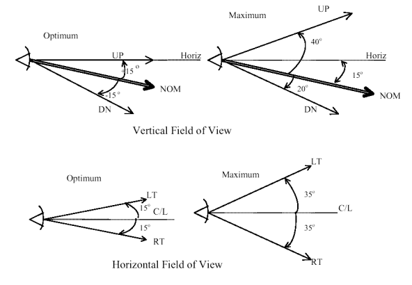
[Amdt 25/11]
CS 25.1323 Airspeed indicating system
ED Decision 2016/010/R
(See AMC 25.1323)
For each airspeed indicating system, the following apply:
(a) Each airspeed indicating instrument must be approved and must be calibrated to indicate true airspeed (at sea-level with a standard atmosphere) with a minimum practicable instrument calibration error when the corresponding pitot and static pressures are applied.
(b) Each system must be calibrated to determine the system error (that is, the relation between IAS and CAS) in flight and during the accelerated takeoff ground run. The ground run calibration must be determined –
(1) From 0·8 of the minimum value of V1, to the maximum value of V2, considering the approved ranges of altitude and weight; and
(2) With the wing-flaps and power settings corresponding to the values determined in the establishment of the take-off path under CS 25.111 assuming that the critical engine fails at the minimum value of V1.
(c) The airspeed error of the installation, excluding the airspeed indicator instrument calibration error, may not exceed 3% or five knots, whichever is greater, throughout the speed range, from –
(1) VMO to 1·23 VSR1 with wing-flaps retracted; and
(2) 1·23 VSR0 to VFE with wing-flaps in the landing position.
(d) From 1·23 VSR to the speed at which stall warning begins, the IAS must change perceptibly with CAS and in the same sense, and at speeds below stall warning speed the IAS must not change in an incorrect sense. (See AMC 25.1323(d).)
(e) From VMO to VMO + ⅔ (VDF – VMO) the IAS must change perceptibly with CAS and in the same sense, and at higher speeds up to VDF the IAS must not change in an incorrect sense. (See AMC 25.1323(e))
(f) There must be no indication of air-speed that would cause undue difficulty to the pilot during the take-off between the initiation of rotation and the achievement of a steady climbing condition.
(g) The effects of airspeed indicating system lag may not introduce significant takeoff indicated airspeed bias, or significant errors in takeoff or accelerate-stop distances.
(h) Each system must be arranged, so far as practicable, to prevent malfunction or serious error due to the entry of moisture, dirt, or other substances. (See AMC 25.1323(h).)
(i) Reserved
(j) Where duplicate airspeed indicators are required, their respective pitot tubes must be far enough apart to avoid damage to both tubes in a collision with a bird.
[Amdt 25/16]
[Amdt 25/18]
AMC 25.1323(d) Airspeed indicating system
ED Decision 2003/2/RM
An acceptable means of compliance when demonstrating a perceptible speed change between 1.23 VSR to stall warning speed is for the rate of change of IAS with CAS to be not less than 0.75."
AMC 25.1323(e) Airspeed indicating system
ED Decision 2003/2/RM
An acceptable means of compliance when demonstrating a perceptible speed change between VMO to VMO + 2/3 (VDF - VMO) is for the rate of change of IAS with CAS to be not less than 0.50."
AMC 25.1323(h) Airspeed indicating system
ED Decision 2003/2/RM
The design and installation of the pitot system should be such that positive drainage of moisture is provided, chafing of the tubing and excessive distortion at bends is avoided, and the lag and the possibility of moisture blockage in the tubing should be kept to an acceptable minimum.
CS 25.1324 Flight instrument external probes
ED Decision 2015/008/R
(See AMC 25.1324)
Each flight instrument external probes systems, including, but not necessarily limited to, pitot tubes, pitot-static tubes, static probes, angle of attack sensors, side slip vanes, and temperature probes, must be heated or have an equivalent means of preventing malfunction in the heavy rain conditions defined in Table 1 of this paragraph, in the icing conditions as defined in Appendices C and P, and the following icing conditions specified in Appendix O:
(a) For aeroplanes certificated in accordance with CS 25.1420(a)(1), the icing conditions that the aeroplane is certified to safely exit following detection;
(b) For aeroplanes certificated in accordance with CS 25.1420(a)(2), the icing conditions that the aeroplane is certified to safely operate in and the icing conditions that the aeroplane is certified to safely exit following detection;
(c) For aeroplanes certificated in accordance with CS 25.1420(a)(3), all icing conditions.
Table 1 – Rain test conditions
|
Altitude Range |
Liquid Water Content |
Horizontal Extent |
Droplet MVD |
||
|
(ft) |
(m) |
(g/m3) |
(km) |
(NM) |
(µm) |
|
0 to 10 000 |
0 to 3 000 |
1 |
100 |
50 |
500 to 2 000 |
|
6 |
5 |
3 |
|||
|
15 |
1 |
0.5 |
|||
[Amdt 25/16]
AMC 25.1324 Flight instrument external probes
ED Decision 2018/005/R
CS 25.1324 requires each flight instrument external probes systems, including, but not necessarily limited to Pitot tubes, Pitot-static tubes, static probes, angle of attack sensors, side slip vanes and temperature probes, to be heated or have an equivalent means of preventing malfunction in the heavy rain conditions of table 1 of CS 25.1324 and in the icing conditions as defined in the Appendices C and P, and in Appendix O (or a portion of Appendix O) of CS-25.
It is unlikely that the icing conditions critical to the equipment will be encountered during flight tests. Consequently, it is anticipated that tests should be conducted in wind tunnel simulated icing environment to supplement the icing flight test data (natural or tanker) as necessary.
The following AMC provides some guidance related to the test setup and the conditions to be tested.
Note: Engine sensors such as pressure/temperature probes must meet CS-E certification specifications. However, when the signals from these sensors are used by the aeroplane system(s), the aeroplane manufacturer must ensure that the involved engine sensor meets CS 25.1324 specifications. Coordination of this activity should be ensured with the engine manufacturer.
1. Acronyms
SAT: Static Air Temperature
LWC: Liquid Water Content
MVD: Median Volume Diameter
MMD: Median Mass Dimension
L(i): “Liquid” supercooled water conditions
M(i): Mixed phase icing conditions: icing conditions that contain both supercooled water and ice crystals.
G(i): Glaciated conditions: icing conditions totally composed of ice crystals.
R(i): Rain conditions
SD: supercooled droplet
SLD: supercooled large drop
WC: water content
2. Wind Tunnels
All conditions must be appropriately corrected to respect the similarity relationship between actual and wind tunnel conditions (due to pressure and scale differences for example). It is the applicant responsibility to determine and justify the various derivations and corrections to be made to the upstream conditions in order to determine actual test conditions (local and scaled). When the tests are conducted in non-altitude conditions, the system power supply and the external aerodynamic and atmospheric conditions should be so modified as to represent the required altitude condition as closely as possible.
The icing wind tunnel calibration should have been verified, in accordance with SAE ARP 5905 with an established programme to maintain calibration of the facility. Calibration records should be examined to ensure the local liquid water concentration at the location of the probe complies with values required in the test specification.
3. Test setup
The test setup installation in the wind tunnel must be shown to be equivalent to the installation on the aircraft. In particular, the probe must be installed in such a way that the heat sink capacity of the mount is equal to or greater than the aircraft installation.
Surface temperature measurements of the probe mounting are typically made during icing wind tunnel tests to verify thermal analysis and to allow extrapolation to conditions not reachable due to the wind tunnel limitations.
4. Local conditions
The Water Content (WC) values provided in this AMC or in the Appendices C, O and P to CS-25 are upstream values, independent of the aircraft installation. Local WC values (at the probe location) need to be derived from the upstream values according to the streamline behaviour around the aircraft. Overconcentration of the WC at the probe location may occur due to the aerodynamic effects of the fuselage in particular.
Local conditions should be determined based on many parameters which could include:
— Aircraft specific
— Aircraft fuselage shape
— Probe location on aircraft fuselage (X, Y, Z coordinates)
— Aircraft speed and altitude (Climb, Cruise, Descent …)
— Environmental Conditions specific
— Type (SD, SLD, Crystals, Rain)
— Size (from 0 to 2 000 micron)
— Density
— Probe specific:
— mast/strut length
Concerning the type and size of the particles, the local WC should be computed considering the full distribution of the particles sizes that is actually present in the real atmosphere, even if the wind tunnel tests are then performed at a given single size (20 micron for supercooled droplets, 150 micron for ice crystals, 500 to 2 000 micron for rain drops). The local conditions may also be affected by the “bouncing effect” and “shattering effect” for solid particles or the “splashing effects” for large liquid particles. As no model exists today to represent ice particles trajectories and these particular effects, an assessment based on the best available state of the art shall be made.
5. Operational Conditions
The conditions are to be tested at several Mach and Angle of Attack (AoA) values in order to cover the operational flight envelope of the aircraft. It is the applicant responsibility to select and justify, for each of the conditions listed in each Cloud Matrix below, the relevant operational conditions to be tested (Mach, AoA and Mode…).
It is expected that several operational conditions will be identified for each environmental conditions but exhaustive testing is not intended.
6. Power supply
The heating power supply used during the tests should be the minimum value expected at the probe location on the aircraft. It is commonly accepted to test the probe at 10 % below the nominal rated voltage.
7. Flight deck indication
When a flight instrument external probe heating system is installed, CS 25.1326 requires an alert to be provided to the flight crew when that flight instrument external probe heating system is not operating or not functioning normally.
All performances of the probe ice protection system, in particular the icing tests described in this AMC are expected to be demonstrated with equipment selected with heating power set to the minimum value triggering the flight deck indication.
8. Test article selection
To be delivered, an article has to meet an Acceptance Test Procedure (ATP) established by the equipment supplier. The ATP is a production test performed on each item to show it meets the performance specification. Both the performance of the ice protection system and the icing tests described hereafter are expected to be demonstrated with an equipment selected at the lowest value of the ATP with respect to the acceptability of the heating performance. This can be accomplished by adjusting the test voltage, heating cycles and/or any other applicable parameters, to simulate the lowest performing probe. Note that this has to be applied in addition to the power supply reduction mentioned in paragraph 6 above.
9. Mode of Operation
The modes of operation of the probe are to be assessed in the two following tests. However, depending on the mode of operation of the heating systems, other intermediate modes may have to be tested (e.g. if heating power is varied as a function of the outside temperature, etc.)
a. Anti-icing test:
During this test, the icing protection of the probe (typically resistance heating) is assumed to be switched “on” prior exposure to icing conditions.
b. De-icing test:
During this test, the icing protection of the probe (typically resistance heating) should be ‘off’ until 0.5 inch of ice has accumulated on the probe. For ice crystal tests in de-icing mode, since no accretion is usually observed, an ‘off’ time duration should be agreed before the test. In the past, a 1-minute time duration without heating power has been accepted. This mode need not be tested if, in all operational scenarios (including all dispatch cases), the probe heating systems are activated automatically at aircraft power ‘On’ and cannot be switched to manual operation later during the flight. Furthermore, in assessing whether or not this mode needs to be tested, any failure conditions that are not demonstrated to be extremely improbable, and that may lead to probe heating supply interruptions, should be considered.
10. Supercooled Liquid (SL) Conditions
The following proposed test points are intended to provide the most critical conditions of the complete CS-25 Appendix C icing envelope, however, a Critical Points Analysis (CPA) may be used to justify different values.
10.1 Stabilized conditions
Table 1: Stabilized Liquid icing test conditions
|
Test # |
SAT (°C) |
Altitude Range |
LWC(*) (g/m3) |
Duration (min) |
MVD(*) (µm) |
|
|
SL1 |
− 20 |
0 to 22000 ft. |
0 to 6706 m |
0.22 to 0.3 |
15 |
15 to 20 |
|
SL2 |
− 30 |
0 to 22000 ft. |
0 to 6706 m |
0.14 to 0.2 |
15 |
15 to 20 |
|
SL3 |
− 20 |
4000 to 31000 ft. |
1219 to 9449m |
1.7 to 1.9 |
5 |
15 to 20 |
|
SL4 |
− 30 |
4000 to 31000 ft. |
1219 to 9449 m |
1 to 1.1 |
5 |
15 to 20 |
(*) Note:
The upstream LWC values of the table are based on CS-25 Appendix C and correspond to a droplet diameter of 20 µm or 15 µm. Considering that the local collection efficiency is function of the MVD and the probe location with respect to the boundary layer, and that the upstream LWC value is higher for an MVD of 15 µm as compared to 20 µm, the applicant shall establish the conditions leading to the highest local LWC at probe location and test accordingly.
It is acceptable to run the tests at the highest determined local LWC but using a droplet diameter of 20 µm since most of the wind tunnel are calibrated for that value.
10.2 - Cycling conditions
A separate test should be conducted at each temperature condition of Table 2 below, the test being made up of repetitions of either the cycle:
a. 28 km in the conditions of column (a) appropriate to the temperature, followed by 5 km in the conditions of column (b) appropriate to the temperature, for a duration of 30 minutes, or
b. 6 km in the conditions of column (a) appropriate to the temperature, followed by 5 km in the conditions of column (b) appropriate to the temperature, for a duration of 10 minutes.
Table 2: Cycling Liquid icing test conditions
|
Test # |
SAT (°C) |
Altitude Range |
LWC (g/m³) |
MVD (µm) |
||
|
(ft) |
(m) |
|||||
|
|
|
|
|
(a) |
(b) |
20 |
|
SL6 |
− 10 |
17 000 |
5182 |
0.6 |
2.2 |
|
|
SL7 |
− 20 |
20 000 |
6096 |
0.3 |
1.7 |
|
|
SL8 |
− 30 |
25 000 |
7620 |
0.2 |
1.0 |
|
11. Supercooled Large Drop Liquid Conditions
Based on the design of the probe, the drop size may not be a significant factor to consider as compared to the other parameters and in particular the Liquid Water Content (LWC). The SLD LWC defined in Appendix O (between 0.18 and 0.44 g/m3) is largely covered by the Appendix C continuous maximum LWC (between 0.2 and 0.8 g/m3) and the Appendix C intermittent maximum LWC (between 0.25 and 2.9 g/m3).
Testing SLD conditions may not be necessary if it can be shown that the Supercooled Liquid Conditions of Appendix C are more critical. If some doubt exists, the applicant shall propose a set of critical test points to cover adequately the Icing Environment defined in the Appendix O.
For showing compliance with the CS-25 certification specifications relative to SLD icing conditions represented by Appendix O, the applicant may use a comparative analysis. AMC 25.1420(f) provides guidance for comparative analysis.
12. Mixed Phase (M) and Glaciated (G) Conditions
The applicant should propose a set of critical test points to cover adequately the Icing Environment as proposed in Appendix P of CS-25.
Testing should be performed at representative altitude as the effect of altitude on probe behaviour is not yet fully understood, unless demonstration can be made that application of scaling laws leads to conservative approach of testing.
The following considerations shall be taken into account.
12.1 Glaciated Conditions
As indicated in the Appendix P, the total water content (TWC) in g/m3 has been assessed based upon the adiabatic lapse defined by the convective rise of 90 % relative humidity air from sea level to higher altitudes and scaled by a factor of 0.65 to a standard cloud length of 17.4 nautical miles (NM).
In service occurrences show that several pitot icing events in Glaciated Conditions, above 30 000 ft are outside of the Appendix P domain in term of altitude and outside air temperature. In that context, the Appendix P, Figure 1 (Convective cloud ice crystal envelope) should be enlarged to encompass ISA +30°C conditions. Furthermore, a reported event occurred at a temperature of – 70 °C. Testing may not be possible at such a low temperature due to simulation tool limitations. However, the presence of Ice Crystals has been observed, and it is anticipated that an extrapolation of existing test data at higher temperature should allow assessing the predicted performance of the probe heating down to this minimum temperature.
In addition, based on several sources of information including the EUROCAE WG-89, the Agency is of the opinion that the standard cloud of 17.4 NM and the associated average TWC concentration values provided by Appendix P may not provide the most conservative conditions for Flight Instrument External Probes testing.
The ‘max’ or ‘peak’ TWC concentration values should be considered instead of the ‘17.4 NM’ values provided by the Appendix P. These ‘max’ or ‘peak’ values are available in FAA document DOT/FAA/AR-09/13. They correspond to the ‘17.4 NM’ values multiplied by a factor of 1.538 (1/0.65). The ‘max’ concentration values (TWC) are provided below:
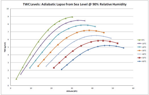
12.2 Mixed Phase Conditions
In service occurrences show several pitot icing events in Mixed phase conditions, between 20 000 and 30,000 feet, outside of the Appendix P domain in term of altitude and outside air temperature.
Based on several sources of information including the EUROCAE WG-89, the Agency is of the opinion that the ‘2.6 NM’ TWC concentration values should be considered instead of the ‘17.4 NM’ values, as the CS-25 Appendix C Intermittent conditions provide data for a 2.6 NM cloud.
The ‘2.6 NM’ values are given by the ‘17.4 NM’ values scaled by the F factor for 2.6 NM clouds which is 1.175 and are provided below:
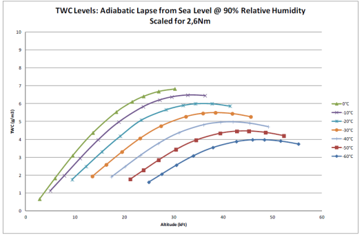
It is commonly recognised that below -40°C no liquid conditions exist anymore. Therefore testing in mixed phase conditions does not need to consider temperatures below -40°C.
12.3 Ice Particles
Several methods of generating ice particles are used in testing and produce a wide range of particle sizes. Some methods of generating ice particles results in irregular shapes which are difficult to quantify in terms of mean particle diameter. It is acceptable to specify ice particle sizes based on the available range of ice particle generation techniques in the MMD range of 50 to 200 µm as provided in Appendix P to CS-25. Higher values may be used if justified.
For mixed phase icing, the heat requirements are driven primarily by the quantity of ice collected in the probe rather than the size of the ice particles. Supercooled liquid droplet MVD size of 20 µm should be used.
12.4 Duration
For each condition a minimum of two minutes exposure time should be tested. This is the minimum time needed to reach a steady state and stabilised condition.
12.5 Total Air Temperature probe design consideration
It is recognised that due to the intrinsic function of the total air temperature probes it may not be possible to design the temperature sensor with sufficient heating capability to ensure both adequate protection across the complete icing environment of CS-25 Appendix P and accurate temperature measurements. In this case, it may be acceptable that the temperature probe is not fully protected over a portion of the Appendix P icing environment provided that the malfunction of the probe will not prevent continued safe flight and landing. System safety assessments must include common mode failure conditions. Mitigation for potential icing related failures at the aircraft level should be accomplished as required by the Air Data System and/or by the primary data consumers. Examples of mitigation methods include comparing air data from multiple sources and from sources of dissimilar technologies.
13. Rain (R) Conditions
Flight instrument external probes must be evaluated in the heavy rain conditions provided in Table 1 of CS 25.1324. A test temperature below 10°C is considered acceptable. Testing may be performed at a higher temperature if it can be demonstrated that the increase in evaporation rate due to the higher ambient temperature does not decrease the severity of the test.
The efficiency of the drainage of the probe may depend on the aircraft airspeed. The applicant should, therefore, consider testing conditions including, at a minimum, low and high airspeed values in the rain conditions envelope.
14. Pass/fail criteria
The pass/fail criteria of a given test are as follows:
The output of the probe should quickly stabilize to the correct value after the start of an anti-icing test or once the icing protection is restored in a de-icing test. This value has to be agreed before the test between the applicant and the Agency, and it must stay correct as long as the icing protection is maintained. The measurement is considered to be correct if any observed fluctuation, when assessed by the applicant, has no effect at the aircraft level.
In addition, for pitot probes and especially during ice crystal or mixed phase conditions tests, it should be observed that the measured pressure is not ‘frozen’ (pressure signal without any noise, i.e. completely flat), which would indicate an internal blockage resulting in a captured pressure measurement.
After each test, any water accumulating in the probe connection line should be collected and assessed. The amount of water trapped in the probe (i.e. in the line conveying the air to the electronics) should not interfere with the output correctness when the probe is installed on the aeroplane.
[Amdt 25/16]
[Amdt 25/18]
[Amdt 25/21]
CS 25.1325 Static pressure systems
ED Decision 2015/008/R
(a) Each instrument with static air case connections must be vented to the outside atmosphere through an appropriate piping system.
(b) Each static port must be designed and located so that:
(1) the static pressure system performance is least affected by airflow variation, or by moisture or other foreign matter, and
(2) the correlation between air pressure in the static pressure system and true ambient atmospheric static pressure is not changed when the aeroplane is exposed to icing conditions. The static pressure system shall comply with CS 25.1324.
(c) The design and installation of the static pressure system must be such that –
(1) Positive drainage of moisture is provided; chafing of the tubing and excessive distortion or restriction at bends in the tubing is avoided; and the materials used are durable, suitable for the purpose intended, and protected against corrosion; and
(2) It is airtight except for the port into the atmosphere. A proof test must be conducted to demonstrate the integrity of the static pressure system in the following manner:
(i) Unpressurised aeroplanes. Evacuate the static pressure system to a pressure differential of approximately 33.86 HPa, (1 inch of mercury) or to a reading on the altimeter, 305 m (1 000 ft) above the aeroplane elevation at the time of the test. Without additional pumping for a period of 1 minute, the loss of indicated altitude must not exceed 30 m (100 ft) on the altimeter.
(ii) Pressurised aeroplanes. Evacuate the static pressure system until pressure differential equivalent to the maximum cabin pressure differential for which the aeroplane is type certificated is achieved. Without additional pumping for a period of 1 minute, the loss of indicated altitude must not exceed 2% of the equivalent altitude of the maximum cabin differential pressure or 30 m (100 ft), whichever is greater.
(d) Each pressure altimeter must be approved and must be calibrated to indicate pressure altitude in a standard atmosphere, with a minimum practicable calibration error when the corresponding static pressures are applied.
(e) Each system must be designed and installed so that the error in indicated pressure altitude, at sea-level, with a standard atmosphere, excluding instrument calibration error, does not result in an error of more than ±9 m (±30 ft) per 185 km/hr (100 knots) speed for the appropriate configuration in the speed range between 1·23 VSR0 with wing-flaps extended and 1·7 VSR1 with wing-flaps retracted. However, the error need not be less than ±9 m (±30 ft).
(f) If an altimeter system is fitted with a device that provides corrections to the altimeter indication, the device must be designed and installed in such manner that it can be bypassed when it malfunctions, unless an alternate altimeter system is provided. Each correction device must be fitted with a means for indicating the occurrence of reasonably probable malfunctions, including power failure, to the flight crew. The indicating means must be effective for any cockpit lighting condition likely to occur.
(g) Except as provided in sub-paragraph (h) of this paragraph, if the static pressure system incorporates both a primary and an alternate static pressure source, the means for selecting one or the other source must be designed so that –
(1) When either source is selected, the other is blocked off; and
(2) Both sources cannot be blocked off simultaneously.
(h) For un-pressurised aeroplanes, sub-paragraph (g)(1) of this paragraph does not apply if it can be demonstrated that the static pressure system calibration, when either static pressure source is selected, is not changed by the other static pressure source being open or blocked.
[Amdt 25/16]
CS 25.1326 Flight instrument external probes heating systems alert
ED Decision 2015/008/R
(See AMC 25.1326)
If a flight instrument external probe heating system is installed, an alert must be provided to the flight crew when the flight instrument external probe heating system is not operating or not functioning normally. The alert must comply with the following requirements:
(a) The alert provided must conform to the Caution alert indications.
(b) The alert provided must be triggered if either of the following conditions exists:
(1) The flight instrument external probe heating system is switched ‘off’.
(2) The flight instrument external probe heating system is switched ‘on’ and is not functioning normally.
[Amdt 25/16]
AMC 25.1326 Flight instrument external probes heating systems alert
ED Decision 2015/008/R
CS 25.1326 requires that if a flight instrument external probe heating system is installed, an alert must be provided to the flight crew when the flight instrument external probes heating system is not operating or not functioning normally.
It is expected that probe heating system failures are indicated to the flight crew if such failures have an impact on the performance of the heating system to the extent of having an “effect on operational capability or safety” (see CS 25.1309).
In accordance with CS 25.1309(c) and CS 25.1322(b), a Caution category of alert is required by CS 25.1326 for immediate crew awareness and subsequent crew action.
It should be assumed that icing conditions exist during the failure event. The decision to provide heating system failure indication should not be based on the numerical probability of the failure event. If the failure could potentially have hazardous or catastrophic consequences, then this failure must be indicated.
The reliability of the system performing the probe heating system failure detection and alerting should be consistent with the safety effect induced by the failure. Refer to AMC 25.1309, chapter 9(c) for more detailed guidance.
[Amdt No: 25/16]
CS 25.1327 Direction Indicator
ED Decision 2003/2/RM
(See AMC 25.1327)
(a) Each magnetic direction indicator must be installed so that its accuracy is not excessively affected by the aeroplane’s vibration or magnetic fields.
(b) The magnetic direction indicator required by CS 25.1303(a)(3) may not have a deviation, after compensation, in normal level flight, greater than 10 degrees on any heading.
(c) Direction indicators required by CS 25.1303(b)(6) must have an accuracy adequate for the safe operation of the aeroplane.
AMC 25.1327 Direction Indicator
ED Decision 2018/005/R
This AMC addresses the accuracy of stabilised magnetic heading systems, required for safe operation of the aeroplane. These systems include means to compensate or correct for errors induced by stable magnetic effects in the aeroplane. Additional effects due to electromagnetic transients and configuration changes are not normally “compensated” by the magnetic heading system and are also included in this AMC.
Should the correction become unavailable (either intentionally or unintentionally), the effects of the resulting heading indication should be considered for safe operation of the aeroplane. This AMC addresses the condition where correction is available and the condition where correction is not available (or failed).
In most circumstances, heading information is not directly used as the primary means of navigation. This condition should permit the applicant to show that the accuracy adequate for the safe operation of the aeroplane may be different than what is defined in this AMC.
1. After correction the cumulative deviation on any heading should not exceed 5°, based on the following:
a. A change in deviation due to the equipment of the heading system components, the total of which should not exceed 2°.
b. A change in deviation due to the current flow in any item of electrical equipment and its associated wiring is permissible, but should not exceed 1°. The total cumulative effect for all combinations of equipment, with all combinations of electrical load, should not exceed 2°.
c. A change in deviation due to the movement of any component, (e.g. controls or undercarriage) in normal flight is permissible, but should not exceed 1°.
2. If correction fails or is not available, the change in deviation due to the proximity of all equipment containing magnetic material should not exceed 2°.
3. For magnetic heading indications obtained via geographic (true) heading, the accuracy of the heading indication should account for the accuracy of the magnetic variation data based on geographic position. This variation may change over time.
Acceptable accuracy values have been found to be:
2 degrees (Latitudes between 50°S and 50°N)
3 degrees (Latitudes between 50°N and 73°N)
3 degrees (Latitudes between 50°S and 60°S)
5 degrees (Latitudes between 73°N and 79°N)
8 degrees (Latitudes between 79°N and 82°N)
The applicant may propose different accuracy values after consultation with the EASA.
In areas of known magnetic unreliability (e.g. the magnetic poles), the magnetic variation error can be very large, so the magnetic heading indications (if output) should not be relied upon.
4. For geographic (true) heading indications (such as those provided by Inertial Reference Units), the accuracy should be better or equal to 1°.
Note: On aeroplanes with a short cruising range, the above limits may be extended after consultation with EASA. For aeroplanes that do not depend on direction or heading information for navigation (VOR, ILS, FMS, GPS), the above limits may be extended after consultation with EASA.
[Amdt 25/21]
CS 25.1329 Flight Guidance System
ED Decision 2007/020/R
(See AMC Nos. 1 and 2 to CS 25.1329)
(a) Quick disengagement controls for the autopilot and autothrust functions must be provided for each pilot. The autopilot quick disengagement controls must be located on both control wheels (or equivalent). The autothrust quick disengagement controls must be located on the thrust control levers. Quick disengagement controls must be readily accessible to each pilot while operating the control wheel (or equivalent) and thrust control levers.
(b) The effects of a failure of the system to disengage the autopilot or autothrust functions when manually commanded by the pilot must be assessed in accordance with the specifications of CS 25.1309.
(c) Engagement or switching of the flight guidance system, a mode, or a sensor must not produce a transient response affecting the control or flight path of the aeroplane any greater than a minor transient.
(d) Under normal conditions, the disengagement of any automatic control functions of a flight guidance system must not produce a transient response affecting the control or flight path of the aeroplane any greater than a minor transient.
(e) Under rare-normal or non-normal conditions, the disengagement of any automatic control functions of a flight guidance system must not produce a transient response affecting the control or flight path of the aeroplane any greater than a significant transient.
(f) The function and direction of motion of each command reference control (e.g., heading select, vertical speed) must be readily apparent or plainly indicated on, or adjacent to, each control if necessary to prevent inappropriate use or confusion.
(g) Under any condition of flight appropriate to its use, the flight guidance system must not:
— produce unacceptable loads on the aeroplane (in accordance with CS 25.302), or
— create hazardous deviations in the flight path.
This applies to both fault-free operation and in the event of a malfunction, and assumes that the pilot begins corrective action within a reasonable period of time.
(h) When the flight guidance system is in use, a means must be provided to avoid excursions beyond an acceptable margin from the speed range of the normal flight envelope. If the aircraft experiences an excursion outside this range, the flight guidance system must not provide guidance or control to an unsafe speed.
(i) The flight guidance system functions, controls, indications, and alerts must be designed to minimise flight crew errors and confusion concerning the behaviour and operation of the flight guidance system. Means must be provided to indicate the current mode of operation, including any armed modes, transitions, and reversions. Selector switch position is not an acceptable means of indication. The controls and indications must be grouped and presented in a logical and consistent manner. The indications must be visible to each pilot under all expected lighting conditions.
(j) Following disengagement of the autopilot, a warning (visual and aural) must be provided to each pilot and be timely and distinct from all other cockpit warnings.
(k) Following disengagement of the autothrust function, a caution must be provided to each pilot.
(l) The autopilot must not create an unsafe condition when the flight crew applies an override force to the flight controls.
(m) During autothrust operation, it must be possible for the flight crew to move the thrust levers without requiring excessive force. The autothrust response to flight crew override must not create an unsafe condition.
[Amdt 25/4]
AMC No. 1 to CS 25.1329 Flight Guidance System
ED Decision 2020/024/R
1 PURPOSE
This AMC provides interpretative material and acceptable means of compliance with the specifications of CS 25.1329 for Flight Guidance Systems. These means are intended to provide guidance to supplement the engineering and operational judgment that must form the basis of any compliance demonstration.
2 RELATED CERTIFICATION SPECIFICATIONS
CSs
The following are related CS standards:
|
CS 25.115 |
Take-off flight path |
|
CS 25.302 |
Interaction of systems and structures |
|
CS 25.671 |
Control systems, General |
|
CS 25.672 |
Stability augmentation and automatic and power-operated systems |
|
CS 25.677 |
Trim systems |
|
CS 25.777 |
Cockpit controls |
|
CS 25.779 |
Motion and effect of cockpit controls |
|
CS 25.781 |
Cockpit control knob shape |
|
CS 25.901 |
Powerplant, General, Installation– |
|
CS 25.903 |
Powerplant, General, Engines |
|
CS 25.1301 |
Equipment, General, Function and installation– |
|
CS 25.1309 |
Equipment, systems, and installations |
|
CS 25.1322 |
Flight Crew Alerting System |
|
CS 25.1419 |
Ice protection |
|
CS 25.1420 |
Supercooled large drop icing condition |
|
CS 25.1581 |
Aeroplane Flight Manual, General |
|
CS-AWO |
All Weather Operations |
3 RELATED ADVISORY MATERIAL
EASA Acceptable Means of Compliance (AMC) and FAA Advisory Circulars (FAA AC).
The following guidance and advisory materials are related to this AMC:
|
AMC 20-115 |
Software Considerations for Airborne Systems and Equipment Certification |
|
AMC 25.1309 |
System Design and Analysis |
|
AMC 25.1322 |
Alerting Systems |
|
AMC 25.1581 |
Aeroplane Flight Manual |
|
AMC 25-11 |
Electronic Display Systems |
|
FAA AC 20-129 |
Airworthiness Approval of Vertical Navigation (VNAV) Systems for use in the U.S. National Airspace System (NAS) and Alaska |
|
FAA AC 25-7C |
Flight Test Guide for Certification of Transport Category Airplanes |
|
FAA AC 25-12 |
Airworthiness Criteria for the Approval of Airborne Windshear Warning Systems in Transport Category Airplanes |
|
FAA AC 120-28D |
Criteria for Approval of Category III Weather Minima for Takeoff, Landing, and Rollout |
|
FAA AC 120-29A |
Criteria for Approval of Category I and Category II Weather Minima for Approach |
|
FAA AC 120-41 |
Criteria for Operational Approval of Airborne Wind Shear Alerting and Flight Guidance Systems |
4 RELATED DOCUMENTS
JAA documents:
|
JAR-OPS 1 |
Commercial Air Transportation (Aeroplanes) |
Industry documents.
The following are related Industry Standards that may be useful in the design process:
|
SAE ARP5366 |
Autopilot, Flight Director and Autothrust Systems |
|
SAE ARP4754A/ EUROCAE ED-79A |
Guidelines for development of civil aircraft and systems |
|
SAE ARP4100 |
Flight Deck and Handling Qualities Standards for Transport Aircraft |
|
SAE ARP4761 |
Guidelines and Methods for Conducting the Safety Assessment Process on Civil Airborne Systems and Equipment |
|
RTCA DO-160G/ |
Environmental Conditions and Test Procedures for Airborne Equipment |
|
RTCA DO-254/ |
Design Assurance Guidance for Airborne Electronic Hardware |
|
DOT/FAA/CT-96/1 |
Human Factors Design Guide for Acquisition of Commercial-Off-the-Shelf Subsystems, Non-Developmental Items, and Developmental Systems. |
5 DEFINITIONS AND ACRONYMS
The following definitions apply to the specifications of CS 25.1329 and the guidance material provided in this AMC. They should not be assumed to apply to the same or similar terms used in other regulations or AMC material. Terms for which standard dictionary definitions apply are not defined in this AMC.
|
Abnormal Condition |
See Non-normal |
|
Advisory |
EASA: Crew awareness is required and subsequent crew action may be required. (AMC 25.1322) |
|
Alert |
A generic term used to describe a flight deck indication meant to attract the attention of the flight crew to a non-normal operational or aeroplane system condition without implying the degree or level of urgency for recognition and corrective action by the crew. Warnings, Cautions and Advisories are considered to be Alerts. EASA definition: A signal to the crew intended to draw their attention to the existence of an abnormality, system fault or aircraft condition and to identify it. (AMC 25.1322) |
|
Analysis |
The terms “analysis” and “assessment” are used throughout. Each has a broad definition and the two terms are to some extent interchangeable. However, the term analysis generally implies a more specific, more detailed evaluation, while the term assessment may be a more general or broader evaluation but may include one or more types of analysis (AMC 25.1309). |
|
Arm |
A condition where the intent to transition to a new mode or state has been established but the criteria necessary to make that transition has not been satisfied. |
|
Assessment |
See the definition of analysis above (AMC 25.1309). |
|
Autopilot |
The autopilot function provides automatic control of the aeroplane, typically in pitch, roll, and yaw. The term includes the sensors, computers, power supplies, servo-motors/actuators and associated wiring, necessary for its function. It includes any indications and controllers necessary for the pilot to manage and supervise the system. Any part of the autopilot that remains connected to the primary flight controls when the autopilot is not in use is regarded as a part of the primary flight controls. |
|
Autothrust |
The autothrust function provides automatic control of the thrust of the aeroplane. The term includes the sensors, computers, power supplies, servo-motors/actuators and associated wiring, necessary for its function. It includes any indications and controllers necessary for the pilot to manage and supervise the system. Any part of the autothrust that remains connected to the engine controls when the autothrust is not in use is regarded as a part of the engine control system. |
|
Caution |
A flight deck indication that alerts the flight crew to a non-normal operational or aeroplane system condition that requires immediate crew awareness. Subsequent pilot corrective compensatory action will be required. |
|
Cognitive Task Analysis |
An analysis that focuses on the mental processes, skills, strategies, and use of information required for task performance. |
|
Complex |
A system is Complex when its operation, failure modes, or failure effects are difficult to comprehend without the aid of analytical methods (AMC 25.1309). |
|
Conformal |
Positioned and scaled with respect to the outside view |
|
Control Wheel Steering (CWS) |
A Flight Guidance System (FGS) function which, when engaged, enables the pilot/first officer to manually fly the aeroplane by positioning the flight control surfaces using the autopilot servos. The positions of the flight deck controls (e.g., control column, control wheel) are determined by the FGS, which converts them into autopilot servo commands. The autopilot servos, in turn, drive the appropriate flight control surfaces. |
|
Conventional |
A system is considered to be Conventional if its functionality, the technological means used to implement its functionality, and its intended usage are all the same as, or closely similar to, that of previously approved systems that are commonly-used (AMC 25.1309). |
|
Engage |
A steady state that exists when a flight crew request for mode or system functionality has been satisfied. |
|
Error |
An omission or incorrect action by a crewmember or maintenance personnel, or a mistake in requirements, design, or implementation (AMC 25.1309). |
|
Failure |
An occurrence that affects the operation of a component, part, or element such that it can no longer function as intended (this includes both loss of function and malfunction). NOTE: Errors may cause failures, but are not considered to be failures (AMC 25.1309). |
|
Failure Condition |
A condition having an effect on the aeroplane and/or its occupants, either direct or consequential, which is caused or contributed to by one or more failures or errors, considering flight phase and relevant adverse operational or environmental conditions, or external events (AMC 25.1309) |
|
Fail Operational System |
A system capable of completing an operation, following the failure of any single element or component of that system, without pilot action. |
|
Fail Passive System |
A system which, in the event of a failure, results in: (a) no significant deviation in the aircraft flight path or attitude and (b) no out-of-trim condition at disengagement that is not easily controlled by the pilot. |
|
Flight Director |
A visual cue or set of cues that are used during manual control of the aeroplane as command information to direct the pilot how to manoeuvre the aeroplane, usually in pitch, roll and/or yaw, to track a desired flight path. The flight director, displayed on the pilot's primary head down attitude indicator (ADI) or head up display (HUD), is a component of the flight guidance system and is integrated with airborne attitude, air data and navigation systems. |
|
Flight Guidance System |
A system consisting of one or more of the following elements: (a) autopilot, (b) flight director, (c) automatic thrust control, and any interactions with stability augmentation and trim systems. |
|
Flight Management System |
An aircraft area navigation system and associated displays and I/O device(s) having complex multi-waypoint lateral (LNAV) and vertical (VNAV) navigation capability (or equivalent), data entry capability, data base memory to store route and instrument flight procedure information, and display readout of navigation parameters. The Flight Management System provides guidance commands to the FGS for the purpose of automatic navigation and speed control when the FGS is engaged in an appropriate mode or modes (e.g., VNAV, LVAV, RNAV). |
|
Head-Up Display (HUD) |
A transparent optical display system located level with and between the pilot and the forward windscreen. The HUD displays a combination of control, performance, navigation, and command information superimposed on the external field of view. It includes the display element, sensors, computers and power supplies, indications and controls. It is integrated with airborne attitude, air data and navigation systems, and as a display of command information is considered a component of the light guidance system. |
|
Inadvertent |
A condition or action that was not planned or intended. |
|
Latent Failure |
A failure is latent until it is made known to the flight crew or maintenance personnel. A significant latent failure is one, which would in combination with one or more specific failures, or events result in a Hazardous or Catastrophic Failure Condition (AMC 25.1309). |
|
Limit Flight Envelope |
This envelope is the most outside flight envelope, generally associated with aeroplane design limits |
|
Mode |
A mode is system configuration that corresponds to a single (or set of) FGS behaviour(s). |
|
Non-normal Condition |
A condition or configuration of the aeroplane that would not normally be experienced during routine flight operations - usually due to failures or non-routine operating conditions (e.g., excessive out-of-trim due to fuel imbalance or under certain ferry conditions). |
|
Normal Condition |
Any fault free condition typically experienced in normal flight operations. Operations typically well within the aircraft flight envelope, and with routine atmospheric and environmental conditions. |
|
Normal Flight Envelope |
The range of altitude and operating speeds that are defined by the aeroplane manufacturer as consistent with conducting flight operations for which the aeroplane is designed. This envelope is generally associated with practical, routine operation and/or prescribed conditions, whether all-engine or engine inoperative. |
|
Override |
An action taken by the flight crew intended to prevent, oppose or alter an operation being conducted by a flight guidance function, without first disengaging that function. |
|
Rare Normal Condition |
A fault-free condition that is experienced infrequently by the aeroplane due to significant environmental conditions (e.g., significant wind, turbulence, or icing, etc.) |
|
Redundancy |
The presence of more than one independent means for accomplishing a given function or flight operation (AC/AMC 25.1309). |
|
Select |
The flight crew action of requesting functionality or an end state condition. |
|
Significant transient |
See “transient.” |
|
Stability Augmentation System |
Automatic systems, which provide or enhance stability for specific aerodynamic characteristics of an aeroplane (e.g., Yaw Damper, Longitudinal Stability Augmentation System, Mach Trim). |
|
System |
A combination of components, parts, and elements that are inter-connected to perform one or more specific functions (AMC 25.1309). |
|
Transient |
A disturbance in the control or flight path of the aeroplane that is not consistent with response to flight crew inputs or current environmental conditions. Minor transient: A transient that would not significantly reduce safety margins, and which involves flight crew actions that are well within their capabilities involving a slight increase in flight crew workload or some physical discomfort to passengers or cabin crew. Significant transient: A transient that would lead to a significant reduction in safety margins, a significant increase in flight crew workload, discomfort to the flight crew, or physical distress to passengers or cabin crew, possibly including non-fatal injuries. NOTE: The flight crew should be able to respond to any significant transient without: exceptional piloting skill, alertness, or strength, forces greater than those given in CS 25.143(cd), and accelerations or attitudes in the aeroplane that might result in further hazard to secured or non-secured occupants. |
|
Warning |
A flight deck indication that alerts the flight crew to a non-normal operational or aeroplane system requiring immediate recognition. Immediate corrective or compensatory action by the flight crew is required. |
|
AC |
Advisory Circular (FAA) |
|
ACAS |
Airborne Collision Avoidance System |
|
AMC |
Acceptable Means of Compliance |
|
AFM |
Aeroplane Flight Manual |
|
AGL |
Above Ground Level |
|
AIM |
Airman’s Information Manual |
|
ARP |
Accepted and Recommended Practice |
|
ATC |
Air Traffic Control |
|
AWO |
All Weather Operations |
|
CG |
Centre of Gravity |
|
CDI |
Course Deviation Indicator |
|
CWS |
Control Wheel Steering |
|
DA |
Decision Altitude |
|
DA(H) |
Decision Altitude (Height) |
|
DME |
Distance Measuring Equipment |
|
EFIS |
Electronic Flight Instrument System |
|
EVS |
Enhanced Vision System |
|
FAA |
Federal Aviation Administration |
|
FCOM |
Flight Crew Operations Manual |
|
F/D |
Flight Director |
|
FGS |
Flight Guidance System |
|
FLCH |
Flight Level Change |
|
FMA |
Flight Mode Annunciator |
|
FMS |
Flight Management System |
|
GA |
Go-around |
|
GLS |
GNSS Landing System |
|
GNSS |
Global Navigation Satellite System |
|
GPWS |
Ground Proximity Warning System |
|
HDD |
Head Down Display |
|
HUD |
Head-Up Display |
|
IAS |
Indicated Air Speed |
|
ICAO |
International Civil Aviation Organization |
|
ILS |
Instrument Landing System |
|
IMA |
Integrated Modular Avionics |
|
IMC |
Instrument Meteorological Conditions |
|
JAA |
Joint Aviation Authorities |
|
LNAV |
Lateral Navigation |
|
LOC |
Localizer |
|
MDA(H) |
Minimum Descent Altitude (Height) |
|
MLS |
Microwave Landing System |
|
MSL |
Mean Sea Level |
|
MSP |
Mode Select Panel |
|
MUH |
Minimum Use Height |
|
NAV |
Navigation |
|
ND |
Navigation Display |
|
NDB |
Non Directional Beacon |
|
NPA |
Notice of Proposed Amendment |
|
NPRM |
Notice of Proposed Rulemaking |
|
PF |
Pilot Flying |
|
PFD |
Primary Flight Display |
|
PNF |
Pilot Not Flying |
|
RNAV |
Area Navigation |
|
RNP |
Required Navigation Performance |
|
RTO |
Rejected Takeoff |
|
RVSM |
Reduced Vertical Separation Margin |
|
SAE |
Society of Automotive Engineering |
|
SVS |
Synthetic Vision System |
|
TCAS |
Traffic Collision Alert System |
|
TCS |
Touch Control Steering |
|
TO |
Takeoff |
|
TOGA |
Takeoff or Go-around |
|
VMC |
Visual Meteorological Conditions |
|
VNAV |
Vertical Navigation |
|
VOR |
VHF Omni Range |
|
WAT |
Weight Altitude Temperature |
This advisory material replaces material previously provided in AMC 25.1329 for Automatic Pilots. The automatic control and guidance systems in current aircraft have evolved to a level that dictates a revision to current advisory material.
There have been dramatic changes in technology and system design, which have resulted in much higher levels of integration, automation, and complexity. These changes have also redefined the allocation of functions and interfaces between systems. Relatively simple, dedicated systems have been replaced with digital multi-function systems with more modes, and automatic changes in modes of operation. The introduction of fly-by-wire flight control systems has created new interface considerations for the FGS elements. These new systems are capable of providing better performance, increased safety and decreased workload. But if designed without consideration for the criteria in this AMC, these systems could also be confusing and not immediately intuitive for the flight crew. Significant operational experience has been gained on new generation systems and guidance material is provided herein based on that experience.
This advisory material is provided for Flight Guidance Systems, which include any autopilot functions, flight director functions, automatic thrust control functions and any interactions with stability augmentation and trim functions.
7 GENERAL
The FGS is primarily intended to assist the flight crew in the basic control and tactical guidance of the aeroplane. The system may also provide workload relief to the pilots and may provide a means to fly a flight path more accurately to support specific operational requirements (e.g. RVSM, RNP, etc.).
The applicant should establish, document and follow a design philosophy that supports the intended operational use regarding the FGS behaviour; modes of operation; pilot interface with controls, indications, and alerts; and mode functionality.
Description of the FGS behaviour and operation should be addressed from flight crew and maintenance perspectives in appropriate documentation and training material.
Subsequent sections of this advisory material provide interpretative material and acceptable means of compliance with CS 25.1329 and the applicability of other CS-25 rules to FGS (e.g., CS 25.1301, CS 25.1309). The demonstrated means of compliance may include a combination of analysis, laboratory testing, flight-testing, and simulator testing. The applicant should coordinate with the authorities early in the certification programme, via a certification plan, to reach agreement on the methods to be used to demonstrate compliance.
7.1 Flight Guidance System Functions
The following functions, when considered separately and together, are considered elements of a Flight Guidance System:
— Flight guidance and control (e.g., autopilot, flight director displayed head-down or head-up);
— Autothrottle/autothrust systems;
— Interactions with stability augmentation and trim systems; and
— Alerting, status, mode annunciation, and situation information associated with flight guidance and control functions.
The FGS includes those functions necessary to provide guidance and control in conjunction with an approach and landing system, such as:
— the Instrument Landing System (ILS),
— the Microwave Landing System (MLS) or
— the Global Navigation Satellite System (GNSS) Landing System (GLS).
The FGS also includes those functions necessary to provide guidance and control in conjunction with a Flight Management System (FMS). The FGS does not include the flight planning and the generation of flight path and speed profiles tied to waypoints and other flight planning aspects of the Flight Management System (FMS). However, it does include the interface between the FMS and FGS necessary for the execution of flight path and speed commands.
For the purpose of this AMC the term “FGS” includes all the equipment necessary to accomplish the FGS function, including the sensors, computers, power supplies, servo-motors/actuators, and associated wiring. It includes any indications and controllers necessary for the pilot to manage and supervise the system.
Any part of the FGS that remains mechanically connected to the primary flight controls or propulsion controls when the Flight Guidance System is not in use is regarded as a part of the primary flight controls and propulsion system, and the provisions for such systems are applicable.
7.3 Compliance with CS 25.1329
Table 7.3-A lists the relevant paragraphs of CS 25.1329 and provides an indication where acceptable means of compliance with each paragraph may be found within this AMC.
TABLE 7.3-A.
Where Means of Compliance Can Be Found in this AMC
|
Section / Paragraph |
Rule Text |
Where Acceptable Means of Compliance Found in this AMC |
|
CS 25.1329(a) |
Quick disengagement controls for the autopilot and autothrust functions must be provided for each pilot. The autopilot quick disengagement controls must be located on both control wheels (or equivalent). The autothrust quick disengagement controls must be located on the thrust control levers. Quick disengagement controls must be readily accessible to each pilot while operating the control wheel (or equivalent) and thrust control levers. |
Section 8.1, Autopilot Engagement/Disengagement and Indications Section 8.3, Autothrust Engagement/Disengagement and Indications
|
|
CS 25.1329(b) |
The effects of a failure of the system to disengage the autopilot or autothrust functions when manually commanded by the pilot must be assessed in accordance with the specifications of CS 25.1309. |
Section 8.1, Autopilot Engagement/Disengagement and Indications Section 8.3, Autothrust Engagement/Disengagement and Indications Section 13.6, Safety Assessment – Failure to Disengage the FGS |
|
CS 25.1329(c) |
Engagement or switching of the flight guidance system, a mode, or a sensor must not produce a transient response affecting the control or flight path of the aeroplane any greater than a minor transient. |
Section 8, FGS Engagement, Disengagement, and Override Section 13, Safety Assessment |
|
CS 25.1329(d) |
Under normal conditions, the disengagement of any automatic control functions of a flight guidance system must not produce a transient response affecting the control or flight path of the aeroplane any greater than a minor transient. |
Section 8, FGS Engagement, Disengagement, and Override Section 13, Safety Assessment |
|
CS 25.1329(e) |
Under rare-normal or non-normal conditions the disengagement of any automatic control functions of a flight guidance system must not produce a transient response affecting the control or flight path of the aeroplane any greater than a significant transient. |
Section 8, FGS Engagement, Disengagement, and Override Section 9.3.3, Awareness of Potential Significant Transient Condition (“Bark before Bite”) |
|
CS 25.1329 (f) |
The function and direction of motion of each command reference control (e.g., heading select, vertical speed) must be readily apparent or plainly indicated on, or adjacent to, each control if necessary to prevent inappropriate use or confusion. |
Section 9, Controls, Indications and Alerts |
|
CS 25.1329(g) |
Under any condition of flight appropriate to its use, the Flight Guidance System must not: — produce unacceptable loads on the aeroplane (in accordance with CS 25.302), or — create hazardous deviations in the flight path. This applies to both fault-free operation and in the event of a malfunction, and assumes that the pilot begins corrective action within a reasonable period of time. |
Section 10, Performance of Function Section 13, Safety Assessment Section 14, Compliance Demonstration using Flight Test and Simulation |
|
CS 25.1329(h) |
When the flight guidance system is in use, a means must be provided to avoid excursions beyond an acceptable margin from the speed range of the normal flight envelope. If the aircraft experiences an excursion outside this range, the flight guidance system must not provide guidance or control to an unsafe speed. |
Section 10.4, Speed Protection |
|
CS 25.1329(i) |
The FGS functions, controls, indications, and alerts must be designed to minimize flight crew errors and confusion concerning the behaviour and operation of the FGS. Means must be provided to indicate the current mode of operation, including any armed modes, transitions, and reversions. Selector switch position is not an acceptable means of indication. The controls and indications must be grouped and presented in a logical and consistent manner. The indications must be visible to each pilot under all expected lighting conditions. |
Section 9, Controls Indications and Alerts |
|
CS 25.1329(j) |
Following disengagement of the autopilot, a warning (visual and aural) must be provided to each pilot and be timely and distinct from all other cockpit warnings. |
Section 8.1.2.1, Autopilot Disengagement Alerts Section 13, Safety Assessment |
|
CS 25.1329(k) |
Following disengagement of the autothrust function, a caution must be provided to each pilot. |
Section 8.3.2, Autothrust Disengagement Section 13, Safety Assessment |
|
CS 25.1329(l) |
The autopilot must not create an unsafe condition when the flight crew applies an override force to the flight controls. |
Section 8.4.1, Flight Crew Override of the FGS – Autopilot Section 13, Safety Assessment |
|
CS 25.1329(m) |
During autothrust operation, it must be possible for the flight crew to move the thrust levers without requiring excessive force. The autothrust response to flight crew override must not create an unsafe condition. |
Section 8.4.2, Flight Crew Override of the FGS - Autothrust Section 13, Safety Assessment |
8 Flight Guidance System Engagement, Disengagement and Override
The characteristics of the FGS during engagement, disengagement and override have caused some concern with systems on some aeroplanes. The following criteria should be addressed in the design of a FGS.
8.1 Autopilot Engagement/Disengagement and Indications
Autopilot engagement and disengagement should be accomplished in a manner consistent with other flight crew procedures and tasks, and should not require undue attention.
8.1.1 Autopilot Engagement
Each pilot should be able to select the autopilot function of the flight guidance system with a single switch action. The single switch action should engage pitch and roll axes. The autopilot system should provide positive indication to the flight crew that the system has been engaged. The selector switch position is not acceptable as a means of indication (reference CS 25.1329(i)).
NOTE: If an operational need is identified for split-axis engagement, then annunciation or indication should be provided for each axis.
For aeroplanes with more than one autopilot installed, each autopilot may be individually selected and should be so annunciated. It should not be possible for multiple autopilots to be engaged in different modes.
The engagement of the autopilot should be free of perceptible transients. Under dynamic conditions, including manoeuvring flight, minor transients are acceptable.
Without a flight director engaged, the initial lateral and vertical modes should be consistent with minimal disturbance from the flight path. For example, the lateral mode at engagement may roll the aeroplane to wings level and then hold the aeroplane heading/track or maintain the existing bank angle (if in a normal range). A heading/track pre-select at engagement function may be provided if precautions are taken to ensure that selection reflects the current intent of the flight crew. The modes at engagement should be annunciated and any associated selected target values should be displayed.
With a flight director engaged, the autopilot should engage into a mode consistent (i.e., the same as, or if that is not possible, then compatible with) the active flight director mode of operation. Consideration should be given to the mode into which the autopilot will engage when large commands are present on either or both flight directors. For example, consideration should be given whether to retain the active flight director mode or engage the autopilot into the basic mode, and the implications for current flight path references and targets. The potential for flight crew confusion and unintended changes in flight path or modes should be considered.
Regardless of the method used, the engagement status (and changes in status) of the autopilot(s) should be clearly indicated and should not require undue attention or recall.
For modes that use multiple autopilots, the additional autopilots may engage automatically at selection of the mode or after arming the mode. A means should be provided to determine that adequate autopilot capability exists to support the intended operation (e.g., "Land 2" and "Land 3" are used in some aircraft).
NOTE: The design should consider the possibility that the pilot may attempt to engage the autopilot outside of the normal flight envelope. It is not required that the autopilot should compensate for unusual attitudes or other situations outside the normal flight envelope, unless that is part of the autopilot’s intended function.
In consequence of specifications in CS 25.1329(d), under normal conditions, automatic or manual disengagement of the autopilot must be free of significant transients or out-of-trim forces that are not consistent with the manoeuvres being conducted by the aeroplane at the time of disengagement. If multiple autopilots are engaged, any disengagement of an individual autopilot must be free of significant transients and should not adversely affect the operation of the remaining engaged autopilot(s) CS 25.1329(d)).
Under non-normal or rare-normal conditions (see CS 25.1329(e)), disengagement of the autopilot may result in a significant transient. The flight crew should be able to respond to a significant transient without:
— exceptional piloting skill, alertness, or strength,
— forces greater than those given in CS 25.143(d), and
— accelerations or attitudes in the aeroplane that might result in a hazard to secured or non-secured occupants.
The flight crew should be made aware (via a suitable alerting or other indication) of conditions or situations (e.g., continued out-of-trim) that could result in a significant transient at disengagement. (See Section 9.3.3 on Awareness of Potential Significant Transient Condition (“Bark before Bite”)).
8.1.2.1 Autopilot Disengagement Alerts (see CS 25.1329(j))
Since it is necessary for a pilot to immediately assume manual control following disengagement of the autopilot (whether manual or automatic), a visual and aural warning must be given (CS 25.1329(j)).
Visual warning: a timely visual warning, distinct from all other cockpit warnings, must be provided and must be located in the primary field of view for both pilots. See CS 25.1329(j).
Aural warning: a timely aural warning must be provided and must be distinct from all other cockpit warnings. See CS 25.1329(j). Even when the autopilot is disengaged by a pilot, it should sound for long enough to ensure that it is heard and recognised by the pilot and other flight crew members (at least a single cycle), but not for so long that it adversely affects communication between crew members or that it is a distraction. The aural warning should continue until silenced by one of the following means:
— Activation of an autopilot quick disengagement control;
— Re-engagement of the autopilot; or
— Another acceptable means.
Multiple-autopilot system: Disengagement of an autopilot within a multiple‑autopilot system (e.g., downgraded capability), requiring immediate flight crew awareness and possible timely action, should cause a Caution level alert to be issued to the flight crew.
Disengagement of an autopilot within a multiple-autopilot system, requiring only flight crew awareness, should cause a suitable advisory to be issued to the flight crew.
Disengagement of an autopilot within a multiple-autopilot system (e.g., downgraded capability), requiring immediate flight crew awareness and possible timely action, should cause a Caution level alert to be issued to the flight crew.
Disengagement of an autopilot within a multiple-autopilot system, requiring only flight crew awareness, should cause a suitable advisory to be issued to the flight crew.
8.1.2.2 Quick Disengagement Control (see CS 25.1329(a))
The purpose of the “Quick Disengagement Control” is to ensure the capability for each pilot to manually disengage the autopilot quickly with a minimum of pilot hand/limb movement. The “Quick Disengagement Control” must be located on each control wheel or equivalent CS 25.1329(a) and should be within easy reach of one or more fingers/thumb of the pilot’s hand when the hand is in a position for normal use on the control wheel or equivalent. The “Quick Disengagement Control” should meet the following criteria:
(a) Be accessible and operable from a normal hands-on position without requiring a shift in hand position or grip on the control wheel or equivalent;
(b) Be operable with one hand on the control wheel or equivalent and the other hand on the thrust levers;
NOTE: When establishing location of the quick disengagement control, consideration should be given to:
— its accessibility with large displacements of, or forces on, the control wheel (or equivalent), and
— the possible need to operate the quick disengagement control with the other hand.
(c) Be easily located by the pilot without having to first locate the control visually;
(d) Be designed so that any action to operate the “Quick Disengagement Control” should not cause an unintended input to the control wheel or equivalent; and
(e) Be designed to minimize inadvertent operation and interference with other nearby control wheel (or equivalent) switches/devices (e.g., radio control, trim).
8.1.2.3 Alternative Means of Autopilot Disengagement
When a CS 25.1309 assessment shows a need for an alternative means of disengagement, the following should be addressed:
— Independence,
— The alternate means should be readily accessible to each pilot,
— Latent failure/reliability of the alternate means.
The following means of providing an alternative disengagement have been found to be acceptable:
— Selection of the engagement control to the “off” position.
— Disengage bar on mode selector panel.
— Trim switch on yoke.
NOTE: Use of circuit breakers as a means of disengagement is not considered to be acceptable.
8.1.2.5 Flight Crew Pitch Trim Input
If the autopilot is engaged and the pilot applies manual pitch trim input, either the autopilot should disengage with no more than a minor transient, or pitch trim changes should be inhibited (see CS 25.1329(l)).
8.2 Flight Director Engagement/Disengagement and Indications
Engagement and disengagement should be accomplished consistent with other flight crew procedures and tasks and should not require undue attention.
8.2.1 Flight Director Engagement
A means should be provided for each pilot to select (i.e., turn on) and deselect the flight director for display on their primary flight display (e.g., attitude display). The selection status of the flight director and the source of flight director guidance should be clear and unambiguous. Failure of a selected flight director should be clearly annunciated.
A flight director is considered “engaged” if it is selected and displaying guidance cues.
NOTE: The distinction is made between “engaged” and “selected” because the flight director might be selected, but not displaying guidance cue(s) (e.g., the cue(s) are biased out of view).
If there are multiple flight directors, and if required for crew awareness, indications should be provided to denote which flight director is engaged (e.g., FD1, FD2, HUD source). For aeroplanes with multiple flight directors installed, both flight directors should always be in the same armed and active FGS modes. The selection status of each flight director should be clear and unambiguous for each pilot. In addition, indications should be provided to denote loss of flight director independence (i.e., first officer selection of captain’s flight director).
A flight director should engage into the current modes and targets of an already engaged autopilot or flight director, if any. With no autopilot engaged, the basic modes at engagement of the flight director functions should be established consistent with typical flight operations.
NOTE: The engagement of the pitch axis in Vertical Speed or Flight Path Angle, and engagement of the lateral axis in Heading Hold, Heading Select or Bank Angle Hold have been found to be acceptable.
Since the HUD can display flight guidance, the HUD guidance mode should be indicated to both pilots and should be compatible with the active head-down flight director mode.
Engagement during manoeuvring flight should be considered.
NOTE: The design should consider the safety consequences if it is possible for the flight director to engage outside of the normal flight envelope. It is not required that the flight director should compensate for unusual attitudes or other situations outside the normal flight envelope, unless that is part of the flight director’s intended function.
The flight director command guidance cue(s) will typically be displayed when the flight director is selected and valid command guidance is available or if it is automatically providing guidance as per paragraph 8.2.1.2 below. The flight director guidance cue(s) should be removed when guidance is determined to be invalid. The display of guidance cue(s) (e.g., flight director bars) is sufficient indication that the flight director is engaged.
8.2.1.2 Reactive Windshear Flight Director Engagement
For aeroplanes equipped with a flight director windshear guidance system, flight director engagement should be provided, consistent with the criteria contained in FAA AC’s 25-12 and 120-41.
8.2.2 Flight Director Disengagement
There may be a means for each pilot to readily deselect his or her on-side flight director function. Flight crew awareness of disengagement and de-selection is important. Removal of guidance cue(s) alone is not sufficient indication of de-selection, because the guidance cue(s) may be removed from view for a number of reasons, including invalid guidance, autopilot engagement, etc. Therefore, the flight director function should provide clear and unambiguous indication (e.g., switch position or status) to the flight crew that the function has been deselected.
8.3 Autothrust Engagement/Disengagement and Indications
The autothrust function should be designed with engagement and disengagement characteristics that provide the flight crew positive indication that the system has been engaged or disengaged. Engagement and disengagement should be accomplished in a manner consistent with other flight crew procedures and tasks and should not require undue attention.
The autothrust engagement controls should be accessible to each pilot. The autothrust function must provide the flight crew positive indication that the system has been engaged.
The autothrust function should be designed to prevent inadvertent engagement and inadvertent application of thrust, for both on-ground and in-air operations (e.g., provide separate arm and engage functions).
The autothrust normally should be designed to preclude inadvertent engagement. However, intended modes such as a “wake up” mode to protect for unsafe speeds may be acceptable (see Section 10.4.1 on Low Speed Protection). If such automatic engagement occurs, it should be clear to the flight crew that automatic engagement has occurred, the automatic engagement should not cause any unsafe condition (e.g., unsafe pitch attitudes or unsafe pitching moments), to show compliance with CS 25.1329(c), and the reason for automatic engagement should be clear and obvious to the flight crew.
NOTE: The design should consider the possibility that the pilot may attempt to engage the autothrust function outside of the normal flight envelope or at excessive (or too low) engine thrust. It is not expected that the autothrust feature should compensate for situations outside the normal flight envelope or normal engine operation range, unless that is part of the intended function of the autothrust system.
8.3.2 Autothrust Disengagement
Autothrust disengagement should not cause any unsafe condition (e.g., pitch attitude, pitching moment, or significant thrust transient), to show compliance with CS 25.1329(d), and the disengagement should not preclude, inhibit, or interfere with timely thrust changes for go-around, landing, or other manoeuvres requiring manual thrust changes.
The autothrust normally should be designed to preclude inadvertent disengagement during activation of autothrust modes of operation.
Following disengagement of the autothrust function, positive indication of disengagement should include at least a visual flight crew alert and deletion of autothrust ‘engaged’ status annunciations (to show compliance with CS 25.1329(k)). For automatic disengagement, visual indications should persist until cancelled by flight crew action. For manual disengagement, if an aural is provided, visual indications should persist for some minimum period. If an aural is not provided, the visual indications should persist until cancelled by flight crew action. For aural indication, if provided, an aural alert of sufficient duration and volume should be provided to assure that the flight crew has been alerted that disengagement has occurred. An extended cycle of an aural alert is not acceptable following disengagement if such an alert can significantly interfere with flight crew coordination or radio communication. Disengagement of the autothrust function is considered a Caution alert.
8.3.2.1 Autothrust Quick Disengagement Control
Autothrust quick disengagement controls must be provided for each pilot on the respective thrust control lever as stated in CS 25.1329(a). A single-action, quick disengagement switch should be incorporated on the thrust control so that switch activation can be executed when the pilot’s other hand is on the flight controls. The disengagement control should be positioned such that inadvertent disengagement of the autothrust function is unlikely. Positioning the control on the outboard side has been shown to be acceptable for multiengine aircraft. Thrust lever knob-end-mounted disengagement controls available on both sides to facilitate use by either pilot have been shown to be preferable to those positioned to be accessible by the pilot’s palm.
8.4 Flight Crew Override of the FGS
The following sections discuss criteria related to the situation where the flight crew overrides the FGS.
1) The autopilot should disengage when the flight crew applies a significant override force to the controls. The applicant should interpret “significant” as a force that is consistent with an intention to overpower the autopilot by either or both pilots. The autopilot should not disengage for minor application of force to the controls (e.g., a pilot gently bumping the control column while entering or exiting a pilot seat during cruise).
NOTE: 111 N (25 lbf) at the control column or wheel has been determined to be a significant override force level for other than approach operations on some aircraft types. To reduce nuisance disengagement, higher forces have been found acceptable for certain approach, landing, and go-around operations on some aircraft types. The force to disengage an autopilot is not necessarily the force required at the column to oppose autopilot control (e.g., cause elevator movement). The corresponding forces for a side stick or centre stick controller may be different.
Under normal conditions, a significant transient should not result from autopilot disengagement when the flight crew applies an override force to the controls (to show compliance with CS 25.1329(d).
Sustained or incremental application of force below the disengagement threshold should not result in a hazardous condition (e.g., the automatic trim running that results in unacceptable aeroplane motion if the autopilot were to automatically disengage, or when manually disengaged).
2) If the autopilot is not designed to disengage in response to any override force, then the response shall be shown to be safe (CS 25.1329(l)).
a) The sustained application of an override force should not result in a potential hazard when the flight crew manually disengages the autopilot or abruptly releases the force on the controls. During sustained application of an override force, the automatic trim should not run to oppose the flight crew commands in any manner that would result in unacceptable aeroplane motion. Mitigation may be accomplished through the provision of an appropriate alert and flight crew procedure.
NOTE: The term ‘sustained application of override force’ is intended to describe a force that is applied to the controls, which may be small, slow, and sustained for some period of time. This may be due to an inadvertent crew action or may be an intentional crew action meant to ‘assist’ the autopilot in a particular manoeuvre. (See Chapter 14, Compliance Demonstration Using Flight Test and Simulation, paragraph 14.1.5, Flight Crew Override of the Flight Guidance System, of this AMC for more information.)
b) Transients resulting from an override force: Under normal conditions, a significant transient should not result from manual autopilot disengagement after the flight crew has applied an override force to the controls (CS 25.1239(d)).
NOTE 1: the term ‘override force’ is intended to describe a pilot action that is intended to prevent, oppose or alter an operation being conducted by a flight guidance function, without first disengaging that function. One possible reason for this action could be an avoidance manoeuvre (such as responding to an ACAS/TCAS Resolution Advisory) that requires immediate action by the flight crew and would typically involve a rapid and forceful input from the flight crew.
NOTE 2: For control wheel steering considerations, refer to Section 11.6.
It should be possible for the pilot to readily override the autothrust function and set thrust by moving the thrust levers (or equivalent) with one hand. CS 25.1329(m) requires that the autothrust response to a flight crew override must not create an unsafe condition.
Autothrust functions may be designed to safely remain engaged during pilot override. Alternatively, autothrust functions may disengage as a result of pilot override, provided that the design prevents unintentional autothrust disengagement and adequately alerts the flight crew to ensure pilot awareness.
8.5 FGS Engagement Mode Compatibility
The philosophy used for the mode at engagement of the autopilot, flight director, and autothrust functions should be provided in flight crew training material.
It should not be possible to select incompatible FGS command or guidance functions at the same time (e.g., commanding speed through elevator and autothrust at the same time).
9 Controls, Indications and Alerts
The human-machine interface with the FGS is a key to ensuring safe, effective and consistent FGS operation. The manner in which FGS information is depicted to flight crews is essential to the flight crew awareness, and therefore, the safe operation of the FGS.
The controls, indications, and alerts must be so designed as to minimize flight crew errors and confusion (CS 25.1329(i)). Indications and alerts should be presented in a manner compatible with the procedures and assigned tasks of the flight crew and provide the necessary information to perform those tasks. The indications must be grouped and presented in a logical and consistent manner and be visible from each pilot’s station under all expected lighting conditions (CS 25.1329(i)). The choice of colours, fonts, font size, location, orientation, movement, graphical layout and other characteristics such as steady or flashing should all contribute to the effectiveness of the system. Controls, indications, and alerts should be implemented in a consistent manner.
It is recommended that the applicant evaluate the adequacy and effectiveness of the information provided by the FGS interface (i.e., controls, indications, alerts, and displays) to ensure flight crew awareness of FGS behaviour and operation. See Section 14, Compliance Demonstration using Flight Test and Simulation, for more discussion of appropriate analyses (which may include, for example, cognitive task analysis as a basis for evaluation).
The FGS controls should be designed and located to provide convenient operation to each crewmember and they must be designed to minimize crew errors, confusion and inadvertent operation (CS 25.1329(i)). To achieve this, CS 25,1329(f) requires that command reference controls to select target values (e.g., heading select, vertical speed) should operate as specified in CS 25.777(b) and 25.779(a) for cockpit controls. The function and direction of motion of each control must be readily apparent or plainly indicated on, or adjacent to, each control if needed to prevent inappropriate use or confusion (CS 25,1329(f)). CS 25.781 also provides requirements for the shapes of the knobs. The design of the FGS should address the following specific considerations:
— Differentiation of knob shape and position. (Errors have included confusing speed and heading knobs on the mode selector panel.)
— Design to support correct selection of target values. (Use of a single control (e.g., concentric controls) for selecting multiple command reference targets has resulted in erroneous target value selection.)
— Commonality of control design across different aircraft to prevent negative transfer of learning with respect to operation of the controls. (Activation of the wrong thrust function has occurred due to variation of TOGA and autothrust disengagement function between aeroplane types- negative transfer of learning with respect to operation of the controls.)
— Positioning of individual FGS controls, FMAs, and related primary flight display information so that, as far as reasonably practical, items of related function have similarly related positions. (Misinterpretation and confusion have occurred due to the inconsistent arrangement of FGS controls with the annunciations on the FMA.)
— Design to discourage or avoid inadvertent operation; e.g., engagement or disengagement (to show compliance with CS 25.777(a)).
9.2 Flight Guidance Mode Selection, Annunciation, and Indication
Engagement of the Flight Guidance System functions must be suitably annunciated to each pilot (to show compliance with CS 25.1329(i)), as described in Section 8, Flight Guidance System Engagement, Disengagement, and Override. The FGS mode annunciations must effectively and unambiguously indicate the active and armed modes of operation (CS 25.1329(i)). The mode annunciation should convey explicitly, as simply as possible, what the FGS is doing (for active modes), what it will be doing (for armed modes), and target information (such as selected speed, heading, and altitude) for satisfactory flight crew awareness.
Mode annunciation must indicate the state of the system and not just switch position or selection (CS 25.1329(i)). Mode annunciation should be presented in a manner compatible with flight crew procedures / tasks and consistent with the mode annunciation design for the specific aircraft type (i.e., compatible with other flight deck systems mode annunciations).
Operationally relevant mode changes and, in particular, mode reversions and sustained speed protection, should be clearly and positively annunciated to ensure flight crew awareness. Altitude capture is an example of an operationally relevant mode that should be annunciated because pilot actions may have different effects on the aeroplane. Annunciation of sustained speed protection should be clear and distinct to ensure flight crew awareness. It should be made clear to the pilot if a mode has failed to arm or engage (especially due to invalid sensor data). FGS sub-modes (e.g., sub-modes as the FGS transitions from localizer capture to localizer track) that are not operationally relevant need not be annunciated.
In-service experience has shown that mode annunciation alone may be insufficient (unclear or not compelling enough) to communicate mode changes to the flight crew, especially in high workload situations. Therefore, the safety consequences of the flight crew not recognizing mode changes should be considered. If necessary, an appropriate alert should be used.
Mode annunciations should be located in the forward field of view (e.g., on the primary flight display). Mode selector switch position or status is not acceptable as the sole means of mode annunciation (CS 25.1329(i)). Modes and mode changes should be depicted in a manner that achieves flight crew attention and awareness. Aural notification of mode changes should be limited to special considerations. Colours, font type, font size, location, highlighting, and symbol flashing have historical precedent as good discriminators, when implemented appropriately. The fonts and font size should be chosen so that annunciation of FGS mode and status information is readable and understandable, without eye strain, when viewed by the pilot seated at the design eye position.
Colour should be used in a consistent manner and assure compatibility with the overall use of colour on the flight deck. Specific colours should be used such that the FGS displays are consistent with other flight deck systems, such as a Flight Management System. The use of monochrome displays is not precluded, provided that the aspects of flight crew attention and awareness are satisfied. The use of graphical or symbolic (i.e., non-textual) indications is not precluded. Implementation of such discriminators should follow accepted guidelines as described in applicable international standards (e.g., AMC 25-11) and should be evaluated for their consistency with and integration with the flight deck design. Engaged modes should be annunciated at different locations and with different colours than armed modes to assist in mode recognition. The transition from an armed mode to an engaged mode should provide an additional attention-getting feature, such as boxing and flashing on an electronic display (per AMC 25-11) for a suitable, but brief, period (e.g., ten seconds), to assist in flight crew awareness.
The failure of a mode to engage/arm when selected by the pilot should be apparent. Mode information provided to the pilot should be sufficiently detailed, so that the consequences of the interaction (e.g., ensuing mode or system configuration that has operational relevance) can be unambiguously determined. The FGS interface should provide timely and positive indication when the flight guidance system deviates from the pilot's direct commands (e.g., a target altitude, or speed setting) or from the pilot's pre-programmed set of commands (e.g., waypoint crossing). The interface should also provide clear indication when there is a difference between pilot-initiated commands (e.g., pilot engages positive vertical speed and then selects an altitude that is lower than the aircraft altitude). The default action taken by the FGS should be made apparent.
The operator should be provided with appropriate description of the FGS modes and their behaviour.
9.3 Flight Guidance Alerting (Warning, Caution, Advisory, and Status)
Alerting information should follow the provisions of CS 25.1322 and associated advisory material. Alerts for FGS engagement and disengagement are described in Section 8, Flight Guidance System Engagement, Disengagement, and Override.
There should be some method for the flight crew to determine and monitor the availability or capability of the Flight Guidance System (e.g., for dispatch), where the intended operation is predicated on the use of the FGS. The method of monitoring provided should take account of the hazard resulting from the loss of the autopilot function for the intended operation.
9.3.1 Alerting for Speed Protection
To assure crew awareness, an alert should be provided when a sustained speed protection condition is detected. This is in addition to any annunciations associated with mode reversions that occur as a consequence of invoking speed protection (see Section 10.4, Speed Protection). Low speed protection alerting should include both an aural and a visual component. High-speed protection alerts need only include a visual alert component because of existing high-speed aural alert requirements, but does not preclude giving an earlier alert.
Alerting for speed protection should be consistent with the protection provided and with the other alerts in the flight deck. Care should be taken to set appropriate values for indicating speed protection that would not be considered a nuisance for the flight crew.
9.3.2 Loss of Autopilot Approach Mode
The loss of the approach mode requires immediate flight crew awareness. This may be accomplished through autopilot disengagement and related warning (as required by CS 25.1329(j) and specified in 8.1.2.1 of this AMC). If the autopilot remains engaged and reverts to a non-approach mode, an appropriate aural warning and/or visual alert should be provided.
9.3.3 Awareness of Potential Significant Transient Condition (“Bark before Bite”)
There have been situations where an autopilot is engaged, operating normally, and controlling up to the limit of its authority for an extended period of time, and the flight crew was unaware of the situation. This service experience has shown that, without timely flight crew awareness and action, this situation can progress to a loss of control after autopilot disengagement, particularly in rare normal or non-normal conditions. However, with adequate flight crew awareness and pilot action, loss of control may be prevented.
To help ensure crew awareness and timely action, appropriate alert(s) (generally caution or warning) should be provided to the flight crew for conditions that could require exceptional piloting skill or alertness for manual control following autopilot disengagement (e.g., significantly out of trim). The number and type of alerts required would be determined by the unique situations that are being detected and by the crew procedures required to address those situations. Any alert should be clear and unambiguous, and be consistent and compatible with other flight deck alerts. Care should be taken to set appropriate thresholds for these alerts such that they are not considered a nuisance for the flight crew.
Situations that should be considered for an alert include:
Sustained Lateral Control Command: If the autopilot is holding a sustained lateral control command, it could be indicative of an unusual operating condition (e.g., asymmetric lift due to icing, fuel imbalance, asymmetric thrust) for which the autopilot is compensating. In the worst case, the autopilot may be operating at or near its full authority in one direction. If the autopilot were to disengage while holding this lateral trim, the result would be that the aeroplane would undergo a rolling moment that could possibly take the pilot by surprise. Therefore, a timely alert should be considered to permit the crew to manually disengage the autopilot and take control prior to any automatic disengagement which might result from the condition.
Sustained Longitudinal Out of Trim: If the autopilot is holding sustained longitudinal trim, it could be indicative of an unusual operating condition (e.g., an inoperative horizontal stabilizer) for which the autopilot is compensating. If the autopilot were to disengage while holding this longitudinal trim, the result would be that the aeroplane would undergo an abrupt change in pitch that could possibly take the pilot by surprise. Therefore, a timely alert should be considered to permit the crew to manually disengage the autopilot and take control prior to any automatic disengagement, which might result from the condition.
Bank and Pitch Angles Beyond Those Intended for Autopilot Operations: Most autopilots are designed with operational limits in both the pitch and roll axes, such that those predetermined limits will not be purposely exceeded. If the aeroplane exceeds those limits, it could be indicative of a situation (which may not be covered by items 1. or 2.) that requires the pilot to intervene. Therefore, a timely alert should be considered to bring this condition to the attention of the flight crew to and permit the crew to manually disengage the autopilot and take control prior to any automatic disengagement, which might result.
It is preferable that the autopilot remains engaged during out-of-trim conditions. However, if there is an automatic disengagement feature due to excessive out-of-trim, an alert should be generated and should precede any automatic disengagement with sufficient margin to permit timely flight crew recognition and manual disengagement. See also Section 8.4, Flight Crew Override of the FGS, for related material.
NOTE: This section is not intended to require alerting for all instances of automatic autopilot disengagement. It is intended only for conditions, which, if not addressed, would lead to such disengagement, which, could result in a significant transient for which the pilot may be unprepared. The intent is to provide crew awareness that would allow the flight crew to be prepared with hands on controls and take appropriate corrective action before the condition results in a potentially hazardous aeroplane configuration or state.
NOTE: This section describes alerting requirements for conditions resulting in unintended out-of-trim operation. There are FGS functions that can intentionally produce out-of-trim operation (e.g. parallel rudder operation in align or engine failure compensation modes, pitch trim operation during the approach/landing to provide trim up/flare spring bias, or pitch trim operation for certain types of Speed/Mach trim systems). It is not the intent of this section to require alerts for functions producing intentional out-of-trim conditions. Other system indications (e.g., mode and status annunciations) should be provided to make the crew aware of the operation of these functions where appropriate.
9.3.4 Failures Affecting Flight Director Guidance
Wherever practicable a failure should cause the immediate removal from view of the guidance information. If the guidance information is retained but a warning given instead, it should be such that the pilot cannot fail to observe it whilst using the guidance information.
9.4 FGS Considerations for Head-Up Displays (HUD)
Head-up displays (HUD) have unique characteristics compared to flight displays installed on the instrument panel. Most of these HUD differences are addressed during HUD certification whether or not the HUD provides flight guidance functions. The intent of this section is to address how such HUD differences may affect FGS functions.
9.4.1 Characteristics of HUD Guidance
If the HUD is designed as a supplemental use display system, it does not replace the requirement for standard Head Down Display (HDD) of flight instrument data. The HUD is intended for use during takeoff, climb, cruise, descent, approach and landing under day, night, VMC and IMC conditions. When it can be reasonably expected that the pilot will operate primarily by reference to the HUD, it should be shown that the HUD is satisfactory for manually controlling the aeroplane and for monitoring the performance of the FGS system.
During take off and landing in certain light and visibility conditions, HUD symbology can be extremely dominant in comparison to external visual references. When visual references are relatively dim, extremely active symbology dynamics and guidance cue gains can lead the pilot to make excessively strong corrections. It should be shown that if HUD guidance cues are followed, regardless of the appearance of external visual references, they do not cause the pilot to take unsafe actions.
Generally the criteria for the mechanization of guidance displayed on the HUD would be no different than guidance displayed on the head-down display. See Section 10, Performance of Function, for flight director performance criteria.
However, unlike head-down displays, HUD’s are capable of displaying certain symbology conformal to the outside scene, including guidance cues. Consequently, the range of motion of this conformal symbology, including the guidance, can present certain challenges in rapidly changing and high crosswind conditions. In certain cases, the motion of the guidance and the primary reference cue may be limited by the field of view. It should be shown that, in such cases, the guidance remains usable and that there is a positive indication that it is no longer conformal with the outside scene. It should also be shown that there is no interference between the indications of primary flight information and the flight guidance cues. In take off, approach, and landing FGS modes, the flight guidance symbology should have priority.
Additionally, HUD guidance is often used in cases, like the low visibility approach, where the pilot will need to reference both the information displayed on the HUD and outside references. Consequently, it should be shown that the location and presentation of the HUD information does not distract the pilot or obscure the pilot’s outside view. For example, it would be necessary for the pilot to track the guidance to the runway without having the view of runway references or hazards along the flight path obscured by the HUD symbology.
9.4.2 HUD Flight Guidance System Display
The HUD display should present flight guidance information in a clear and unambiguous manner. Display clutter should be minimized. The HUD guidance symbology should not excessively interfere with pilots’ forward view, ability to visually manoeuvre the aeroplane, acquire opposing traffic, and see the runway environment. Some flight guidance data elements are essential or critical and should not be removed by any de-clutter function.
9.4.3 Head-Up/Head-Down Display Compatibility
The HUD FGS symbology should be compatible and consistent with symbology on other FGS displays such as head-down EFIS instruments. The FGS-related display parameters should be consistent to avoid misinterpretation of similar information, but the display presentations need not be identical. The HUD and head-down primary flight display formats and data sources need to be compatible to ensure that the same FGS-related information presented on both displays have the same intended meaning.
While not all information displayed on the HUD is directly related to the FGS, the pilot is likely to use most of the displayed information while using the HUD-displayed guidance and FGS annunciations. Therefore, when applicable, the guidelines below for the presentation of FGS-related display information should be followed as much as possible. Certain deviations from these guidelines may be appropriate due to conflict with other information display characteristics or requirements unique to head-up displays. These may include minimization of display clutter, minimization of excessive symbol flashing, and the presentation of certain information conformal to the outside scene.
(a) Symbols should be the same format (e.g., a triangle-shaped pointer head-down appears as a triangle pointer head-up; however, some differences in HUD symbology such as the flight director “circle” versus head-down flight director “bars” or “wedge” have been found acceptable);
(b) Information (symbols) should appear in the same general location relative to other information;
(c) Alphanumeric readouts should have the same resolution, units, and labelling (e.g., the command reference indication for “vertical speed” should be displayed in the same foot-per-minute increments and labelled with the same characters as the head-down displays);
(d) Analogue scales or dials should have the same range and dynamic operation (e.g., a Glideslope Deviation Scale displayed head-up should have the same displayed range as the Glideslope Deviation Scale displayed head-down, and the direction of movement should be consistent);
(e) FGS modes (e.g. autopilot, flight director, autothrust) and status state transitions should be displayed on the HUD, and except for the use of colour, should be displayed using consistent methods (e.g., the method used head-down to indicate a flight director mode transitioning from armed to captured should also be used head-up); and
(f) Information sources should be consistent between the HUD and the head-down displays used by the same pilot.
(g) When FGS command information (i.e., flight director commands) are displayed on the HUD in addition to the head-down displays, the HUD depiction and guidance cue deviation “scaling” needs to be consistent with that used on the head-down displays. This is intended to provide comparable pilot performance and workload when using either head-up or head-down displays.
(h) The same information concerning current HUD system mode, reference data, status state transitions, and alert information that is displayed to the pilot flying on the HUD, should also be displayed to the pilot not flying using consistent nomenclature to ensure unambiguous awareness of the HUD operation.
Although HUD’s are typically not classified as integrated caution and warning systems, they may display warnings, cautions, and advisories as part of their FGS function. In this regard, HUD’s should provide the equivalent alerting functionality as the head-down primary flight display(s). Warnings that require continued flight crew attention on the PFD also should be presented on the HUD (e.g., ACAS/TCAS, Windshear, and Ground Proximity Warning annunciations). If master alerting indications are not provided within the peripheral field of view of the pilot while using the HUD, the HUD should provide annunciations that inform the pilot of Caution and/or Warning conditions (ARP-5288, V12).
For monochrome HUD’s, appropriate use of attention-getting properties such as flashing, outline boxes, brightness, size, and/or location are necessary to adequately compensate for the lack of colour normally assigned to distinguish and call attention to Cautions and warnings.
For multi-colour HUD’s, the use of red, amber, or yellow for symbols not related to Caution and warning functions should be avoided, so that the effectiveness of distinguishing characteristics of true warnings and cautions is not reduced.
Single HUD installations rely on the fact that the non-flying pilot will monitor the head-down instruments and alerting systems, for failures of systems, modes, and functions not associated with primary flight displays.
Dual HUD installations require special consideration for alerting systems. It must be assumed that both pilots will be head-up simultaneously, full, or part-time, especially when the HUD is being used as the primary flight reference, or when the HUD is required equipment for the operation being conducted. If master alerting indications are not provided within the peripheral field of view of each pilot while using the HUD, then each HUD should provide annunciations that direct the pilot’s attention to head-down alerting displays. The types of information that must trigger the HUD master alerting display are any Cautions or warnings not already duplicated on the HUD from head-down primary displays, as well as any Caution level or warning level engine indications or system alerts.
NOTE: The objective is to not redirect attention of the pilot flying to other display when an immediate manoeuvre is required (resolution advisory, windshear).
If a Ground Proximity Warning System (GPWS), wind shear detection system, a wind shear escape guidance system, or a Airborne Collision Avoidance System (ACAS) / Traffic alert and Collision Avoidance System (TCAS) is installed, then the guidance, warnings and annunciations required to be a part of these systems, and normally required to be in the pilot’s primary field of view, should be displayed on the HUD.
9.4.5 Upset/Unusual Attitude Recovery Guidance
Upsets due to wake turbulence or other environmental conditions may result in near instantaneous excursions in pitch and bank angles and a subsequent unusual attitude.
If the HUD is designed to provide guidance for recovery from upsets or unusual attitudes, recovery steering guidance commands should be distinct from, and not confused with, orientation symbology such as horizon “pointers.” For example, a cue for left stick input should not be confused with a cue indicating direction to the nearest horizon. Guidance should be removed if cues become invalid at extreme attitudes, such as zenith, nadir, or inverted. For extreme attitudes it is acceptable to transition to the HDD, provided that the cues to transition from the HUD are clear and unambiguous.
If the HUD is designed to provide orientation only during upsets or unusual attitudes, cues should be designed to prevent them from being mistaken as flight control input commands.
The FGS is expected to perform its intended function throughout the aeroplane’s normal flight envelope. There are considerations for the FGS when operating at the limits of its performance capabilities and when operating under significant environmental conditions. The following sections provide acceptable means of compliance criteria and interpretive material for these considerations.
Where system tolerances have a significant effect on autopilot authority limits, consideration should be given to the effect on autopilot performance. Factors to be considered include but are not limited to tolerances of: servo authority, servo clutch setting, “cam-out” settings, control friction, and sensor tolerances.
The FGS should provide guidance or control, as appropriate, for the intended function of the active mode(s), in a safe and predictable manner within the aeroplane’s normal flight envelope.
The FGS should be designed to operate in all aeroplane configurations for its intended use within the aeroplane’s normal flight envelope to provide acceptable performance for the following types of environmental conditions:
— Winds (light and moderate)
— Wind gradients (light and moderate)
NOTE: In the context of this AMC, ‘wind gradient’ is considered a variation in wind velocity as a function of altitude, position, or time.
— Gusts (light and moderate)
— Turbulence (light and moderate)
— Icing - all icing conditions covered by Appendix C to CS-25 and applicable icing conditions covered by Appendix O to CS-25, with the exception of ‘asymmetric icing’ discussed under ‘Rare Normal Conditions’ in Section 10.2 below. For showing compliance with the CS-25 certification specifications relative to SLD icing conditions represented by Appendix O, the applicant may use a comparative analysis. AMC 25.1420(f) provides guidance for comparative analysis.
NOTE: Representative levels of the environmental effects should be established consistent with the aeroplane’s intended operation.
Any performance characteristics that are operationally significant or operationally limiting should be identified with an appropriate statement or limitation in the Aeroplane Flight Manual (AFM) (Ref. CS 25.1581).
The FGS should perform its intended function during routine aeroplane configuration or power changes, including the operation of secondary flight controls.
Evaluation of FGS performance for compliance should be based on the minimum level of performance needed for its intended functions. Subjective judgment may be applied to account for experience acquired from similar equipment and levels that have been established as operationally acceptable by the end-user.
There are certain operations that dictate a prescribed level of performance. When the FGS is intended for operations that require specific levels of performance, the use of FGS should be shown to meet those specific levels of performance (e.g., Low Visibility Operations – Category II and III operations, Reduced Vertical Separation Minimums (RVSM), Required Navigation Performance (RNP)).
The FGS performance of intended functions should at least be equivalent to that expected of a pilot for a similar task. The AMC No.2 to CS 25.1329 provides for establishing the general behaviour of the FGS. When integrated with navigation sensors or flight management systems, the FGS should satisfy the flight technical error tolerances expected for the use of those systems in performing their intended functions.
The autopilot should provide smooth and accurate control without perceptible sustained nuisance oscillation.
The flight director, in each available display presentation (e.g., single cue, cross-pointer, flight path director) should provide smooth and accurate guidance and be appropriately damped, so as to achieve satisfactory control task performance without pilot compensation or excessive workload.
The autothrust function should provide smooth and accurate control of thrust without significant or sustained oscillatory power changes or excessive overshoot of the required power setting.
The automatic pitch trim function should operate at a rate sufficient to mitigate excessive control surface deflections or limitations of control authority without introducing adverse interactions with automatic control of the aircraft. Automatic roll and yaw trim functions, if installed, should operate without introducing adverse interactions with automatic control of the aircraft.
10.2 Performance in Rare Normal Conditions
The FGS will encounter a wide range of conditions in normal operations, some of which may be infrequent, but levy a greater than average demand on the FGS capabilities. Certain environmental conditions, as listed below, are prime examples. FGS performance during such rare normal conditions should be assessed. Such conditions may degrade FGS performance, but must be safe for FGS operation. The relative infrequency of such conditions may also be a factor in the flight crew’s ability to detect and mitigate, in a timely manner, any limited capability of the FGS to cope with them. The FGS should be limited from operating in environmental conditions in which it cannot be safely operated.
This does not mean that the FGS must be disengaged when rare normal conditions, which may degrade its performance or capability, are encountered. Actually, the FGS may significantly help the flight crew during such conditions. However, the design should address the potential for the FGS to mask a condition from the flight crew or to otherwise delay appropriate flight crew action. See Section 9.3, Flight Guidance Alerting for discussion of alerting under such conditions.
Operations in rare normal environmental conditions may result in automatic or pilot-initiated autopilot disengagement close to the limit of autopilot authority. Autopilot disengagement in rare normal conditions should meet the safety criteria for autopilot disengagement found in Section 8.1 and the criteria for flight guidance alerting in Section 9.3.
For rare normal conditions, the FGS should provide guidance or control, as appropriate for the intended function of the active mode(s), in a safe and predictable manner, both within the normal flight envelope and for momentary excursions outside the normal flight envelope.
The following rare normal environmental conditions should be considered in the design of the FGS:
— Significant winds
— Significant wind gradients
— Windshear (e.g., microburst)
NOTE: For the purpose of this AMC, “windshear” is considered a wind gradient of such a magnitude that it may cause damage to the aircraft. The FGS may also provide suitable autopilot control during windshear. Refer to FAA Advisory Circulars AC 25-12 and AC 120-41 for windshear guidance system requirements.
— Large gusts (lateral, longitudinal, and vertical dimensions)
— Severe and greater turbulence
— Asymmetric icing
10.3 Performance in Non-Normal Conditions
The FGS will occasionally be operating when the aeroplane transitions outside of the normal flight envelope of the aeroplane, when other aeroplane systems experience failure conditions (e.g., inoperative engine, loss of hydraulics) or when the aeroplane experiences certain extraordinary conditions such as significant fuel imbalance, non-standard flap/slat or ferry configurations. Under such circumstances, the FGS characteristics and flight crew interaction with the FGS should be shown to be safe.
10.4 Speed Protection (see 25.1329(h))
The requirement for speed protection is based on the premise that reliance on flight crew attentiveness to airspeed indications, alone, during FGS operation is not adequate to avoid unacceptable speed excursions outside the speed range of the normal flight envelope. Many existing FGS systems have no provisions to avoid speed excursions outside the normal flight envelope. Some FGS systems will remain engaged until the aircraft slows to stall conditions and also to speeds well above VMO/MMO.
The intent of the rule is for the FGS to provide a speed protection function for all operating modes, such that the airspeed can be safely maintained within an acceptable margin of the speed range of the normal flight envelope.
For compliance with the intent of the rule, other systems, such as the primary Flight Control System or the FMS when in a VNAV mode, may be used to provide equivalent speed protection functionality.
If the FGS is providing speed protection function, the following are acceptable means to comply with this rule:
— The FGS may detect the speed protection condition, alert the flight crew and provide speed protection control or guidance.
— The FGS may detect the speed protection condition, alert the flight crew and then disengage the FGS.
— The FGS may detect the speed protection condition, alert the flight crew, and remain engaged in the active mode without providing speed protection control or guidance.
NOTE: If compliance with this requirement is based on use of alerting alone, the alerts should be shown to be appropriate and timely to ensure flight crew awareness and enable the pilot to keep the aeroplane within an acceptable margin from the speed range of the normal flight envelope. See Section 9.3.1 for additional discussion of speed protection alerting.
The design should consider how and when the speed protection is provided for combinations of autopilot, flight directors, and autothrust operation.
Care should be taken to set appropriate values for transitioning into and out of speed protection that the flight crew does not consider a nuisance.
The speed protection function should integrate pitch and thrust control. Consideration should be given to automatically activating the autothrust function when speed protection is invoked. If an autothrust function is either not provided or is unavailable, speed protection should be provided through pitch control alone.
The role and interaction of autothrust with elements of the FMS, the primary flight control system, and the propulsion system, as applicable, should be accounted for in the design for speed protection.
Consideration should be given to the effects of an engine inoperative condition on the performance of speed protection.
When the FGS is engaged in any modes (with the possible exception of approach as discussed in Section 10.4.1.1) for which the available thrust is insufficient to maintain a safe operating speed, the low speed protection function should be invoked to avoid unsafe speed excursions.
Activation of speed protection should take into account the phase of flight, factors such as turbulence and gusty wind conditions, and be compatible with the speed schedules. The low speed protection function should activate at a suitable margin to stall warning consistent with values that will not result in nuisance alerts. Consider the operational speeds, as specified in the Aeroplane Flight Manual (AFM), for all-engine and engine-inoperative cases during the following phases of flight:
— Takeoff.
— During departure, climb, cruise, descent and terminal area operations aeroplanes are normally operated at or above the minimum manoeuvring speed for the given flap configuration.
NOTE: For high altitude operations, it may be desirable to incorporate low speed protection at the appropriate engine out drift-down speed schedule if the FGS (or other integrated sensors/systems) can determine that the cause of the thrust deficiency is due to an engine failure.
— Approach.
NOTE: A low speed alert and a transition to the speed protection mode at approximately 1.2VS, or an equivalent speed defined in terms of VSR, for the landing flap configuration has been found to be acceptable.
— The transition from approach to go-around and go-around climb.
10.4.1.1 Low Speed Protection during Approach Operations
Speed protection should not interfere with the landing phase of flight.
It is assumed that with autothrust operating normally, the combination of thrust control and pitch control during the approach will be sufficient to maintain speed and desired vertical flight path. In cases where it is not, an alert should be provided in time for the flight crew to take appropriate corrective action.
For approach operations with a defined vertical path (e.g., ILS, MLS, GLS, LNAV/VNAV), if the thrust is insufficient to maintain both the desired flight path and the desired approach speed, there are several ways to meet the intent of low speed protection:
(a) The FGS may maintain the defined vertical path as the aeroplane decelerates below the desired approach speed until the airspeed reaches the low speed protection value. At that time the FGS would provide guidance to maintain the low speed protection value as the aeroplane departs the defined vertical path. The FGS mode reversion and low speed alert should be activated to ensure pilot awareness.
NOTE: The pilot is expected to take corrective action to add thrust and return the aeroplane to the defined vertical path or go-around as necessary.
(b) The FGS may maintain the defined vertical path as the aeroplane decelerates below the desired approach speed to the low speed protection value. The FGS will then provide a low speed alert while remaining in the existing FGS approach mode.
NOTE: The pilot is expected to take corrective action to add thrust to cause the aeroplane to accelerate back to the desired approach speed while maintaining the defined vertical path or go-around as necessary.
(c) The FGS may maintain the defined vertical path as the aeroplane decelerates below the desired approach speed until the airspeed reaches the low speed protection value. The FGS will then provide a low speed alert and disengage.
NOTE: The pilot is expected to take corrective action when alerted to the low speed condition and the disengagement of the autopilot, to add thrust and manually return the aeroplane to the desired vertical path or go-around as necessary.
The FGS design may use any one or a combination of these ways to provide acceptable low speed protection.
If the speed protection is invoked during approach such that vertical flight path is not protected, the subsequent behaviour of the FGS after speed protection should be carefully considered. Activation of low speed protection during the approach, resuming the approach mode and reacquiring the defined vertical path, may be an acceptable response if the activation is sufficiently brief and not accompanied by large speed or path deviations.
The interaction between low speed protection and windshear recovery guidance is a special case. Windshear recovery guidance that meets the criteria found in FAA Advisory Circulars AC 25-12 and AC 120‑41 provides the necessary low speed protection when it is activated, and is considered to be acceptable for compliance with CS 25.1329(h). The autopilot should be disengaged when the windshear recovery guidance activates, unless autopilot operation has been shown to be safe in these conditions and provides effective automatic windshear recovery that meets the criteria found in the advisory circulars referenced above.
CS 25.1329(h) states that the means must be provided to avoid excursions beyond an acceptable margin from the speed range of the normal flight envelope VMO and MMO mark the upper speed limit of the normal flight envelope. This is not intended to require, or preclude, high-speed protection based on aeroplane configurations (e.g., flaps).
The following factors should be considered in the design of high-speed protection:
1. The duration of airspeed excursions, rate of airspeed change, turbulence, and gust characteristics.
(a) Operations at or near VMO/MMO in routine atmospheric conditions (e.g., light turbulence) are safe. Small, brief excursions above VMO/MMO, by themselves, are not unsafe.
(b) The FGS design should strive to strike a balance between providing adequate speed protection margin and avoiding nuisance activation of high-speed protection.
NOTE: The following factors apply only to designs that provide high-speed protection through FGS control of airspeed.
2. FGS in altitude hold mode:
(a) Climbing to control airspeed is not desirable, because departing an assigned altitude can be disruptive to ATC and potentially hazardous (for example, in RVSM airspace). It is better that the FGS remain in altitude hold mode.
(b) The autothrust function, if operating normally, should effect high-speed protection by limiting its speed reference to the normal speed envelope (i.e., at or below VMO/MMO).
(c) The basic aeroplane high-speed alert should be sufficient for the pilot to recognize the overspeed condition and take corrective action to reduce thrust as necessary. However, if the airspeed exceeds a margin beyond VMO/MMO (e.g., 11 km/h (6 kt)), the FGS may transition from altitude hold to the overspeed protection mode and depart (climb above) the selected altitude.
3. During climbs and descents:
(a) When the elevator channel of the FGS is not controlling airspeed, the autothrust function (if engaged) should reduce thrust, as needed to prevent sustained airspeed excursions beyond VMO/MMO (e.g., 11 km/h (6 kt)), down to the minimum appropriate value.
(b) When thrust is already the minimum appropriate value, or the autothrust function is not operating, the FGS should begin using the elevator channel, as needed, for high-speed protection.
(c) If conditions are encountered that result in airspeed excursions above VMO/MMO, it is preferable for the FGS to smoothly and positively guide or control the aeroplane back to within the speed range of the normal flight envelope.
The FGS typically will be designed to provide acceptable performance in all standard aeroplane configurations. Operating an aeroplane in icing conditions can have significant implications on the aerodynamic characteristics of the aeroplane (e.g., ice accretion on wings, tail, and engines) and, consequently, on FGS performance. Ice accretion may be slow, rapid, symmetric, or asymmetric. During autopilot operation, the flight crew may not be aware of the gradual onset of icing conditions or the affect that the accumulation of ice is having on the handling qualities of the aeroplane.
Means should be provided to alert the flight crew as described in Section 9.3.
The implication of icing conditions on speed protection should be assessed. If the threshold of the stall warning system is adjusted due to icing conditions, appropriate adjustments should also be made to the FGS low speed protection threshold.
11 CHARACTERISTICS OF SPECIFIC MODES
There are certain operational modes of the FGS that have been implemented in different ways in different aeroplanes and systems. The following sections provide guidance and interpretative material that clarifies the operational intent for these modes and provide criteria that have been shown to be acceptable in current operations. The guidance in this section does not preclude other mode implementations.
Pilot understanding of the mode behaviour is especially important to avoid potential confusion and should be clearly annunciated as described in Section 9.2, Flight Guidance Mode Selection, Annunciation, and Indication.
This section discusses modes that are implemented in many flight guidance systems that are used primarily for lateral/directional control of the aeroplane. The criteria below identify acceptable mode operation based on past operational experience gained from the use of these modes.
In the Heading or Track Hold mode, the FGS should maintain the aeroplane heading or track. For the situation when the aeroplane is in a bank when the Heading or Track Hold mode is engaged, the FGS should roll the aeroplane to a wings-level condition and maintain the heading or track when wings-level is achieved (typically less than 5 degrees of bank angle).
11.1.2 Heading or Track Select
In the Heading or Track Select mode, the FGS should expeditiously acquire and maintain a ‘selected’ heading or track value consistent with occupant comfort. When the mode is initially engaged, the FGS should turn the aeroplane in a direction that is the shortest heading (or track) change to acquire the new heading (or track). Once the heading/track select mode is active, changes in the selected value should result in changes in heading/track. The FGS should always turn the aeroplane in the same direction as the sense of the selected heading change (e.g., if the pilot turns the heading select knob clockwise, the aeroplane should turn to the right), even if the shortest heading (or track) change is in the opposite direction (ref. CS 25.779(a)(1)). Target heading or track value should be presented to the flight crew.
11.1.3 Lateral Navigation Mode (LNAV)
In the LNAV mode, the FGS should acquire and maintain the lateral flight path commanded by a flight management function (that is, FMS or equivalent).
If the aeroplane is not established on the desired lateral path or within the designed path capture criteria when LNAV is selected, the FGS LNAV mode should enter an armed state. The FGS should transition from the armed state to an engaged state at a point where the lateral flight path can be smoothly acquired and tracked.
For an FGS incorporating the LNAV mode during the takeoff or go-around phase, the design should specify manoeuvring capability immediately after takeoff, and limits, should they exist. After takeoff or go-around, manoeuvring should be based upon aircraft performance with the objective to prevent excessive roll attitudes where wingtip / runway impact becomes probable, yet satisfy operational requirements where terrain and / or thrust limitations exist.
This section discusses modes that are implemented in many flight guidance systems that are used primarily for pitch control of the aeroplane. The criteria identified reflect operational experience gained from the use of these modes.
To avoid unconstrained climbs or descents, for any altitude transitions when using applicable vertical modes, the altitude select controller should be set to a new target altitude before the vertical mode can be selected. If the design allows the vertical mode to be selected before setting the target altitude, then consideration should be given to the potential vulnerability of unconstrained climb or descent leading to an altitude violation or Controlled Flight into Terrain. Consideration should also be given to appropriate annunciation of the deviation from previously selected altitude and / or subsequent required pilot action to reset the selected altitude.
In the Vertical Speed mode, the FGS should smoothly acquire and maintain a selected vertical speed.
Consideration should be given to:
— the situation where the selected value is outside of the performance capability of the aeroplane, or
— use of vertical speed mode without autothrust,
potentially leading to a low-speed or high-speed condition, and corresponding pilot awareness vulnerabilities. See Section 10.4, Speed Protection, for discussion of acceptable means of compliance when dealing with such situations.
In the Flight Path Angle mode, the FGS should smoothly acquire and maintain the selected flight path angle.
Consideration should be given to:
— the situation where the selected value is outside of the performance capability of the aeroplane, or
— use of flight path angle mode without autothrust,
potentially leading to a low-speed or high-speed condition, and corresponding pilot awareness vulnerabilities. Acceptable means of compliance have included a reversion to an envelope protection mode or a timely annunciation of the situation.
11.2.3 Airspeed (IAS)/Mach Hold (Speed on elevator)
In the Airspeed/Mach Hold mode, the FGS should maintain the airspeed or Mach at the time of engagement.
11.2.4 Airspeed (IAS)/Mach Select Mode (Speed on elevator)
In the Airspeed/Mach Select mode, the FGS should acquire and maintain a selected airspeed or Mach. The selected airspeed or Mach may be either pre-selected or synchronized to the airspeed or Mach at the time of engagement.
11.2.5 Flight Level Change (FLCH) (Speed on elevator)
In the FLCH mode, the FGS should change altitude in a coordinated way with thrust control on the aeroplane. The autopilot/flight director will typically maintain speed control through elevator. The autothrust function, if engaged, will control the thrust to the appropriate value for climb or descent.
The Altitude Capture mode should command the FGS to transition from a vertical mode to smoothly capture and maintain the selected target altitude with consideration of the rates of climb and descent experienced in service.
In-service experience has shown that certain implementations have the potential to cause pilot confusion that may lead to altitude violations. Accordingly, the following are guidelines for the Altitude Capture mode:
(a) The Altitude Capture mode should be automatically armed to ensure capture of the selected altitude. Note: If the altitude capture mode is armed at all times, annunciation of the armed status is not required. If the FGS is in Altitude Capture, it should be annunciated.
(b) The Altitude Capture mode should engage from any vertical mode if the computed flight path will intercept the selected altitude and the altitude capture criteria are satisfied, except as specified during an approach (e.g., when the glidepath for approach mode is active).
(c) Changes in the climb/descent command references, with the exception of those made by the flight crew using the altitude select controller, should not prevent capture of the target altitude.
(d) The Altitude Capture mode should smoothly capture the selected altitude using an acceptable acceleration limit with consideration for occupant comfort.
(e) The acceleration limit may, under certain conditions, result in an overshoot. To minimize the altitude overshoot, the normal acceleration limit may be increased, consistent with occupant safety.
(f) During Altitude Capture, pilot selection of other vertical modes should not prevent or adversely affect the level off at the target altitude at the time of capture. One means of compliance is to inhibit transition to other pilot-selectable vertical modes (except altitude hold, go-around, and approach mode) during altitude capture, unless the target altitude is changed. If glidepath capture criteria are satisfied during altitude capture, then the FGS should transition to glidepath capture.
(g) The FGS must be designed to minimize flight crew confusion concerning the FGS operation when the target altitude is changed during altitude capture. It must be suitably annunciated and appropriate for the phase of flight (CS 25.1329(i)).
(h) Adjusting the datum pressure at any time during altitude capture should not result in loss of the capture mode. The transition to the pressure altitude should be accomplished smoothly.
(i) If the autothrust function is active during altitude capture the autopilot and autothrust functions should be designed such that the FGS maintains the reference airspeed during the level-off manoeuvre. For example, if the autopilot changes from speed mode to an altitude capture or control mode, then autothrust should transition to a speed mode to maintain the reference airspeed.
The Altitude Hold mode may be entered either by flight crew selection or by transition from another vertical mode.
When initiated by an automatic transition from altitude capture the Altitude Hold mode should provide guidance or control to the selected altitude. The automatic transition should be clearly annunciated for flight crew awareness.
When initiated by pilot action in level flight, the Altitude Hold mode should provide guidance or control to maintain altitude at the time the mode is selected.
When initiated by pilot action when the aeroplane is either climbing or descending, the FGS should immediately initiate a pitch change to arrest the climb or descent, and maintain the altitude when level flight (e.g., <1 m/s (<200 ft/min)) is reached. The intensity of the levelling manoeuvre should be consistent with occupant comfort and safety.
Automatic transition into the Altitude Hold mode from another vertical mode should be clearly annunciated for flight crew awareness.
Any aeroplane response due to an adjustment of the datum pressure should be smooth.
11.2.8 Vertical Navigation Mode (VNAV)
In the VNAV mode, the FGS should acquire and maintain the vertical commands provided by a flight management function (that is, FMS or equivalent).
If the aeroplane is not on the desired FMS path when the VNAV mode is selected, the FGS VNAV mode should go into an armed state, or provide guidance to smoothly acquire the FMS path. The flight crew should establish the aeroplane on a flight profile to intercept the desired FMS path. The FGS should transition from the armed state to an engaged state at a point where the FGS can smoothly acquire and track the FMS path.
When VNAV is selected for climb or descent, the autothrust function (if installed) should maintain the appropriate thrust setting. When levelling after a VNAV climb or descent, the autothrust function should maintain the target speed.
If the aircraft is flying a vertical path (e.g., VNAV Path) the deviation from that path should be displayed in the primary field of view (i.e., the PFD, ND, or other acceptable display).
The FGS should preclude a VNAV climb unless the Mode Selector Panel altitude window is set to an altitude above the current altitude.
Except when on a final approach segment to a runway:
— The FGS should preclude a VNAV descent unless the Mode Selector Panel altitude window is set to an altitude below the current altitude.
— The FGS should not allow the VNAV climb or descent to pass through a Mode Selector Panel altitude.
(See Section 11.5, Special Considerations for VNAV Approach Operations related to selecting a Target Altitude.)
This section discusses modes that are implemented in many flight guidance systems that are used in an integrated manner for pitch, lateral/directional control and thrust management of the aeroplane. The criterion identified reflects operational experience gained from the use of these modes.
In the take off mode, the vertical element of the FGS should provide vertical guidance to acquire and maintain a safe climb out speed after initial rotation for takeoff. If no rotation guidance is provided, the pitch command bars may be displayed during takeoff roll but should not be considered as providing rotation guidance unless it is part of the intended function.
If rotation guidance is provided, consideration should be given to the need to show that the use of the guidance does not result in a tail strike and should be consistent with takeoff methods necessary to meet takeoff performance requirements up to 11 m (35 ft) AGL.
The Autothrust function should increase and maintain engine thrust to the selected thrust limits (e.g., full T/O, de-rate).
The FGS design should address all engine and engine-inoperative conditions consistent with the following takeoff system performance after lift-off:
(a) Takeoff system operation should be continuous and smooth through transition from the runway portion of the takeoff to the airborne portion and reconfiguration for en route climb. The pilot should be able to continue the use of the same primary display(s) for the airborne portion as for the runway portion. Changes in guidance modes and display formats should be automatic.
(b) The vertical axis guidance of the takeoff system during normal operation should result in the appropriate pitch attitude, and climb speed for the aeroplane considering the following factors:
— Normal rate rotation of the aeroplane to the commanded pitch attitude, at VR-18.5 km/h (10 kt) for all engines and VR-9.3 km/h (5 kt) for engine out, should not result in a tail-strike.
— The system should provide commands that lead the aeroplane to smoothly acquire a pitch attitude that results in capture and tracking of the All-Engine Takeoff Climb Speed, V2 + X. X is the All-Engine Speed Additive from the AFM (normally 18.5 km/h (10 kt) or higher). If pitch limited conditions are encountered a higher climb airspeed may be used to achieve the required takeoff path without exceeding the pitch limit.
(c) For engine-out operation, the system should provide commands that lead the aeroplane to smoothly acquire a pitch attitude that results in capture and tracking of the following reference speeds:
— V2, for engine failure at or below V2. This speed should be attained by the time the aeroplane has reached 11m (35 ft) altitude.
— Airspeed at engine failure, for failures between V2 and V2 + X.
— V2 + X, for failures at or above V2 + X. Alternatively, the airspeed at engine failure may be used, provided it has been shown that the minimum takeoff climb gradient can still be achieved at that speed.
If implemented, the lateral element of the takeoff mode should maintain runway heading/track or wings level after lift-off and a separate lateral mode annunciation should be provided.
The vertical element of the FGS Go-around mode should initially rotate the aeroplane, or provide guidance to rotate the aeroplane, to arrest the rate of descent. The autothrust function, if installed, should increase thrust and either, maintain thrust to specific thrust limits, or maintain thrust for an adequate, safe climb.
The FGS should acquire and maintain a safe speed during climb out and aeroplane configuration changes. Typically, a safe speed for go-around climb is V2, but a different speed may be found safe for windshear recoveries (see FAA Advisory Circular AC 25-12). The lateral element of the FGS should maintain heading/track or wings level.
The autothrust function should not exceed thrust limits (e.g., full go-around thrust or de-rated go-around thrust limits) nor reduce thrust, for winds, below the minimum value required for an adequate, safe climb or reduce thrust lever position below a point that would cause a warning system to activate. The initial go-around manoeuvre may require a significant change in pitch attitude. It is acceptable to reduce thrust to lower the pitch attitude for comfort of the occupants when a safe climb gradient has been established. It should be possible for the pilot to re-select the full thrust value if needed.
The go-around mode should engage even if the MSP altitude is at or below the go-around initiation point. The aeroplane should climb until another vertical mode is selected or the MSP altitude is adjusted to an altitude above the present aircraft altitude.
The FGS design should address all engine and engine-out operation. The design should consider an engine failure resulting in a go-around, and the engine failure occurring during an all engine go-around.
Characteristics of the go-around mode and resulting flight path should be consistent with manually flown go-around.
In the Approach mode, the FGS should capture and track a final approach lateral and vertical path (if applicable) from a navigation or landing system (e.g., ILS, MLS, GLS, RNP).
The FGS should annunciate all operationally relevant approach mode annunciations. Modes that are armed, waiting for capture criteria to be satisfied, should be indicated - in addition to the active pre-capture mode. A positive indication of the capture of the previously armed mode should be provided.
The FGS may have sub-modes that become active without additional crew selection. An assessment of the significance of these sub-mode transitions to the flight crew should be made. If assessed to be significant (e.g., Flare), positive annunciation of the transition should be provided.
Glideslope capture mode engagement may occur prior to localizer capture. However, it is the flight crew’s responsibility to ensure proper safe obstacle/terrain clearance when following vertical guidance when the aeroplane is not established on the final lateral path.
Additional guidance and criteria is contained in CS-AWO.
This section discusses modes that are implemented in many flight guidance systems that are used primarily for controlling the engines on the aeroplane. The criterion identified reflects operational experience gained from the use of these modes.
In the Thrust mode, the FGS should command the autothrust function to achieve a selected target thrust value.
In the Speed mode, the FGS should command the autothrust function to acquire and maintain the selected target speed value - assuming that the selected speed is within the speed range of the normal flight envelope. The autothrust system may fly a higher airspeed than the selected target speed during takeoff, or during approach when operating in winds or turbulent conditions.
If such a mode is installed on a specific aircraft, it should work in a similar manner for both automatic and manual landings, when the autothrust function is engaged.
11.5 Special Considerations for VNAV Approach Operations related to selecting a Target Altitude
For approach operations, the FGS vertical modes should allow the pilot to set the target altitude to a missed approach value prior to capturing the final approach segment. This should be possible for capturing from both above and below the final approach segment.
For VNAV Path operations, it should be possible to define a descent path to the final approach fix and another path from the final approach fix to the runway with the target altitude set for the missed approach altitude. Appropriate targets and descent points should be identified by the FMS.
11.6 Control Wheel Steering (Control Steering through the Autopilot)
In the Control Wheel Steering (CWS) mode, the FGS allows the flight crew to manoeuvre the aeroplane through the autopilot. This has implications for control harmony, stability, and crew awareness that need to be thoroughly addressed.
If provided, a CWS mode should meet the following requirements:
(a) It should be possible for the pilot to manoeuvre the aeroplane using the normal flight controls with the CWS mode engaged and to achieve the maximum available control surface deflection without using forces so high that the controllability specifications of CS 25.143 (d) are not met.
(b) The maximum bank and pitch attitudes that can be achieved without overpowering the automatic pilot should be limited to those necessary for the normal operation of the aeroplane.
NOTE: Typically 35 degrees in roll and +20 degrees to -10 degrees in pitch
(c) It should be possible to perform all normal manoeuvres smoothly and accurately without nuisance oscillation. It should be possible also to counter all normal changes of trim due to change of configuration or power, within the range of flight conditions in which control wheel steering may be used, without encountering excessive discontinuities in control force which might adversely affect the flight path.
(d) The stall and stall recovery characteristics of the aeroplane should remain acceptable. It should be assumed that recovery is made with CWS in use unless automatic disengagement of the automatic pilot is provided.
(e) In showing compliance with CS 25.143 (g), account should be taken of such adjustments to trim as may be carried out by the automatic pilot in the course of manoeuvres that can reasonably be expected. Some alleviation may be acceptable in the case of unusually prolonged manoeuvres, provided that the reduced control forces would not be hazardous.
(f) If the use of this mode for takeoff and landing is to be permitted, it should be shown that:
i) Sufficient control, both in amplitude and rate is available without encountering force discontinuities;
ii) Reasonable mishandling is not hazardous (e.g., engaging the automatic pilot while the elevators or ailerons are held in an out-of-trim position);
iii) Runaway rates and control forces are such that the pilot can readily overpower the automatic pilot with no significant deviation in flight path; and
iv) Any lag in aircraft response induced by the CWS mode is acceptable for the intended manoeuvre.
(g) It should not be possible to revert to the CWS mode by applying an input to the control column or wheel unless the autopilot is in a capture mode (e.g., altitude capture, localizer capture). When the force is released, the autopilot should return to the previously engaged capture mode or to the track mode.
NOTE: CWS, if it is provided, is considered to be an autopilot mode, as it is a specific function of the FGS. However, during CWS operation, it is the pilot and not the autopilot that is in control of the aircraft. Operationally, CWS is identical to the pilot flying the aeroplane during manual flight. In both cases, it is the pilot who is in actual control of the flight path and speed of the aeroplane. The only difference is the mechanization of how the actual flight control surfaces are moved. No “automatic” FGS commands are involved during CWS operation. Therefore, sections in this AMC such as those which discuss Speed Protection and performance objectives should be applied to only those autopilot modes with which the FGS is in control of the flight path of the aeroplane and should not be applied to CWS.
NOTE: The terminology “Control Wheel Steering” is currently used by industry to describe several different types of systems. This section is meant to apply only toward those systems that are implemented in a manner as described above. For comparison, several other functions that are similar in nature, but functionally very different, to CWS are described below. This section does not apply to functions of these types.
— Touch Control Steering (TCS) is a function that is available on many business and commuter aircraft. With TCS, a pilot is able to physically disengage the autopilot servos from the flight control system, usually by pushing and holding a button on the control wheel, without causing the autopilot system itself to disengage or lose its currently selected modes. The pilot may then manoeuvre the aeroplane as desired using the aircraft’s flight control system (i.e., the autopilot servos are not part of the control loop). The pilot is then able to reconnect the autopilot servos to the flight control system by releasing the TCS button. Using the new orientation of the aircraft as a basis, the autopilot will then reassume control the aeroplane using the same mode selections as were present before the selection of TCS. This type of system on some aircraft is also sometimes referred to as Control Wheel Steering.
— Also different from CWS is what is referred to as a “supervisory override” of an engaged autopilot. With this function, a pilot is able to physically overpower an engaged autopilot servo by applying force to the flight deck controls. With a supervisory override, the autopilot does not automatically disengage due to the pilot input. This allows the pilot to position the aeroplane as desired using the flight deck controls without first disengaging the autopilot. When the pilot releases the controls, the autopilot reassumes control of the aeroplane using the same mode selections as were present before the supervisory override.
— The descriptions of TCS and supervisory override are intended to be generic. Specific implementations on various aircraft may vary in some aspects.
11.7 Special Considerations for the Integration of Fly-By-Wire Flight Control Systems and FGS
Speed protection features may be implemented in the fly-by-wire flight control system. However, if speed protection is also implemented within the FGS, it should be compatible with the envelope protection features of the fly-by-wire flight control system. The FGS speed protection (normal flight envelope) should operate to or within the limits of the flight control system (limit flight envelope).
Information should be provided to the flight crew about implications on the FGS following degradation of the fly-by-wire flight control systems.
12 FLIGHT GUIDANCE SYSTEM INTEGRATION
Throughout the preceding sections of the document, flight guidance systems and functions have been considered as being separate and distinct from other systems and functions on the aircraft. It is recognized that in complex aircraft designs, the flight guidance functions are closely integrated with other avionics functions, and that the physical integration of these systems, may have a bearing on how aeroplane level safety is assessed. The following paragraphs provide guidance on the likely FGS system integration issues found in more complex aircraft system designs, and the interfaces which should be considered within the bounds of demonstrating the intended function, performance and safety of the FGS.
12.1 System Integration Issues
Integration of other aircraft systems with the FGS has the potential of reducing the independence of failure effects and partitioning between functions. This is particularly the case where hardware and software resources are shared by different systems and functions (e.g., aircraft data highway and Integrated Modular Avionics (IMA) architectures). In addition to considering the reliability and integrity aspects of the FGS as a separate system, it may be necessary to address the effects of FGS failures with respect to fault propagation, detection, and isolation within other systems. The overall effect on the aircraft of a combination of individual system failure conditions occurring as a result of a common or cascade failure, may be more severe than the individual system effect. For example, failure conditions classified under CS 25.1309 as Minor or Major by themselves may have Hazardous effects at the aircraft level, when considered in combination. With regard to isolation of failures, and particularly combination failures, the ability of the alerting system to provide clear and unambiguous information to the flight crew, becomes of significant importance. See also Section 13, Safety Assessment.
Complex and highly integrated avionics issues present greater risk for development error. With non-traditional human-machine interfaces, there is also the potential for operational flight crew errors. Moreover, integration of systems may result in a greater likelihood of undesirable and unintended effects.
Within the FGS, where credit is taken for shared resources or partitioning schemes, these should be justified and documented within the System Safety Analysis. When considering the functional failures of the system, where such partitioning schemes cannot be shown to provide the necessary isolation, possible combination failure modes should be taken into account. An example of this type of failure would be multi-axis active failures, where the control algorithms for more than one axis are hosted on a single processing element. Further, the functional integration of control functions such as control surface trimming, yaw channel, and stability augmentation, while not strictly FGS, should be considered.
In its simplest form, the FGS may be considered as interfacing with sensors that provide the necessary inputs to enable computation of its various functions. Typically, these sensors will include air and inertial data, engine control, and navigation sensors such as ILS, VOR, and DME. In the case of engine control, a feedback loop may also be provided. The FGS may also be considered as providing inner loop closure to outer loop commands. The most common interface is with the FMS, which provides targets for lateral and vertical navigation in the form of steering orders.
In demonstrating the intended function and performance of both the FGS and systems providing outer loop commands, the applicant needs to address potential inconsistencies between limits of the two (e.g., with basic FGS pitch and bank angle limits). Failure to address these points can result in discontinuities, mode switching, and reversions, leading to erroneous navigation and other possible safety issues (e.g., buffet margin at high altitude). Similar issues arise in the inner loop, across the functional interface between FGS and flight controls. In fly-by-wire aircraft, the loss of synchronization between the two can result in mode anomalies and autopilot disengagement.
The applicant should demonstrate the intended function and performance of the FGS across all possible functional interfaces. The alerting system should also be assessed to ensure that accurate and adequate information is provided to the flight crew when dealing with failures across functional interfaces.
CS 25.1309 defines the basic safety specifications for airworthiness approval of aeroplane systems and AMC 25.1309 provides an acceptable means of demonstrating compliance with this rule. This section provides additional guidance and interpretive material for the application of CS 25.1309 to the approval of FGS.
A Safety Analysis document should be produced to identify the Failure Conditions, classify their hazard level according to the guidance of AMC 25.1309, and establish that the Failure Conditions occur with a probability corresponding to the hazard classification or are mitigated as intended. The safety assessment should include the rationale and coverage of the FGS protection and monitoring philosophies employed. The safety assessment should include an appropriate evaluation of each of the identified FGS Failure Conditions and an analysis of the exposure to common mode/cause or cascade failures in accordance with AMC 25.1309. Additionally, the safety assessment should include justification and description of any functional partitioning schemes employed to reduce the effect/likelihood of failures of integrated components or functions.
There may be situations where the severity of the effect of a failure condition identified in the safety analysis needs to be confirmed. Laboratory, simulator or flight test, as appropriate, may accomplish the confirmation.
It is recommended that the Safety Analysis plan is coordinated with the regulatory authority early in the certification program.
One of the initial steps in establishing compliance with CS 25.1309 for a system is to identify the Failure Conditions that are associated with that system. The Failure Conditions are typically characterized by an undesired change in the intended function of the system. The Failure Condition statements should identify the impacted functionality, the effect on the aeroplane and/or its occupants, specify any considerations relating to phase of flight and identify any flight crew action, or other means of mitigation, that are relevant.
Functionality - the primary functions of a FGS may include:
— automatic control of the aeroplane’s flight path utilizing the aeroplane’s aerodynamic control surfaces,
— guidance provided to the flight crew to achieve a particular desired flight path or manoeuvre, through information presented on a head-down or head-up display system, and
— control of the thrust applied to the aeroplane.
Dependent upon the functionality provided in a specific FGS, the failure conditions could potentially impact the following:
— the control of the aeroplane in the pitch, roll and directional axes,
— the control of thrust,
— the integrity and availability of guidance provided to the flight crew,
— the structural integrity of the aeroplane,
— the ability of the flight crew to cope with adverse operating conditions,
— the flight crew’s performance and workload,
— the safety of the occupants of the aeroplane.
NOTE: The safety assessment of a FGS for use in supporting takeoff, approach and landing operations in low visibility conditions is further addressed in CS-AWO.
13.2 Type and Severity of Failure Conditions
The type of the FGS Failure Conditions will depend, to a large extent, upon the architecture, design philosophy and implementation of the system. Types of Failure Conditions can include:
— Loss of function – where a control or display element no longer provides control or guidance
— Malfunction – where a control or display element performs in an inappropriate manner which can include the following sub-types:
a) Hardover – the control or display goes to full displacement in a brief period of time – the resultant effect on the flight path and occupants of the aeroplane are the primary concern.
b) Slowover - the control or display moves away from the correct control or display value over a relatively long period of time – the potential delay in recognizing the situation and the effect on the flight path are the primary concern.
c) Oscillatory - the control or display is replaced or augmented by an oscillatory element – there may be implications on structural integrity and occupant well being.
Failure Conditions can become apparent due to failures in sensors, primary FGS elements (e.g., autopilot, flight director, HUD), control and display elements (e.g., servos, primary flight displays), interfacing systems or basic services (e.g., electrical and hydraulic power).
The severity of the FGS Failure Conditions and their associated classifications will frequently depend on the phase of flight, aeroplane configuration and the type of operation being conducted. The effect of any control system variability (e.g., tolerances and rigging) on Failure Condition should be considered. The severity of the Failure Conditions can also be mitigated by various design strategies (see Section 13.3).
Appendix A presents some considerations for use when assessing the type and severity of condition that results from functional failures. The classifications of Failure Conditions that have been identified on previous aeroplane certification programs are identified. The classifications of Failure Conditions should be agreed with the authority during the CS 25.1309 safety assessment process.
With exception of the Catastrophic failure condition, the classification of failure conditions leading to the imposition of airframe loads should be assessed in accordance with CS 25.302. This requires that the structure be able to tolerate the limit load multiplied by a factor of safety associated with the probability of occurrence of the failure mode. The assessment needs to take into account loads occurring during the active malfunction, recovery or continuation of the flight with the system in the failed state.
Complex integrated systems may require that the total effect resulting from single failure be assessed. For example, some failures may result in a number of Failure Conditions occur which, if assessed individually may be considered a Major effects, but when considered in combination may be Hazardous. Special consideration concerning complex integration of systems can be found in Section 12, Flight Guidance System Integration.
13.3 Failure Condition – Mitigation
The propagation of potential Failure Conditions to their full effect may be nullified or mitigated by a number of methods. These methods could include, but are not limited to, the following:
— failure detection and monitoring,
— fault isolation and reconfiguration,
— redundancy,
— authority limiting, and
— flight crew action to intervene.
Means to assure continued performance of any system design mitigation methods should be identified. The mitigation methods should be described in the Safety Analysis/Assessment document or be available by reference to another document (e.g., a System Description document).
The design of typical FGS allows for the de-selection of control and guidance elements. The long-term effects on occupants and any structural implication of oscillatory failures can be mitigated by de-selection.
13.4 Validation of Failure Conditions
The method of validating of Failure Conditions will depend on the effect of the condition, assumptions made and any associated risk. The severity of some Failure Conditions may be obvious and other conditions may be somewhat subjective. If flight crew action is used to mitigate the propagation of the effect of a Failure Condition, the information available to the flight crew to initiate appropriate action (e.g., motion, alerts, and displays) and the assumed flight crew response should be identified. It is recommended that there be early coordination with the regulatory authority to identify any program necessary to validate any of these assumptions.
The validation options for Failure Conditions include:
— Analysis
— Laboratory Testing
— Simulation
— Flight Test
It is anticipated that the majority of Failure Condition can be validated by analysis to support the probability aspect of the CS 25.1309 assessment. The analysis should take account of architectural strategies (e.g., redundant channels, high integrity components, rate limit/magnitude limiting, etc.).
It may be necessary to substantiate the severity of a Failure Condition effect by ground simulation or flight test. This is particularly true where pilot recognition of the failure condition requires justification or if there is some variability in the response of the aeroplane. Failure Conditions that are projected to be less probable than 10-7 per flight hour, independent of effect severity, need not be demonstrated in flight-test.
Section 14 – Compliance Demonstration using Flight Test and Simulation - provides guidance on the assessment of ‘traditional’ Failure Conditions. New and novel functionality may require additional assessment methods to be agreed with the authority.
The following paragraphs identify specific considerations that should be given to potential Failure Conditions for various phases of flight.
13.5.1 FGS Function during Ground Operations
The potential hazard that may result due to inappropriate autopilot, autothrust or other system control action during maintenance operations, while the aeroplane is parked at the gate or during taxi operations should be assessed. System interlocks or crew or maintenance procedures and placards may mitigate these hazards.
13.5.2 FGS Operations in close proximity to the ground
The response of the aeroplane to failures in an automatic flight control system could have implications on the safety of operations when the aeroplane is close to the ground. For the purpose of this advisory circular, close to the ground can be assumed to be less than 150 m (500 ft) above the lift-off point or touchdown zone or a runway. A specific safety assessment is required if approval is sought for automatic flight control operation where the autopilot is engaged, or remains engaged in close proximity to the ground.
NOTE: Operation in low visibility conditions requires additional consideration and CS AWO Subparts should be used for those additional considerations.
If approval is sought for engagement of the autopilot below 150 m (500 ft) after lift-off, an assessment of the effect of any significant FGS failure conditions on the net vertical flight path, the speed control and the bank angle of the aeroplane should be conducted. An Autopilot Minimum Engage Altitude after Takeoff will be established based, in part, on the characteristics of the aeroplane in response to the failures and the acceptability of flight crew recognition of the condition.
A pilot assessment of certain Failure Conditions may be required (see Section 14 – Compliance Demonstration using Flight Test and Simulation). The minimum engagement altitude/height after takeoff based upon the assessment should be provided in the AFM.
13.5.2.1.1 Vertical Axis Assessment
The operational objective during the initial climb is to maintain an appropriate climb profile to assure obstacle clearance and to maintain an appropriate speed profile during climbout (refer to Section 11, Characteristics of Specific Modes).
FGS Failure Conditions should be assessed for the potential for:
— a significant reduction in the net takeoff flight path below 150 m (500 ft),
— a significant increase in pitch attitude that results in the aeroplane speed dropping to unacceptable values.
Failures Conditions with a probability greater than 1 x 10⁻⁷ per flight hour that have an effect requiring the pilot to intervene should be evaluated for a potential AFM limitations or procedures.
13.5.2.1.2 Lateral Axis Assessment
The operational objective during the initial climb is to maintain an appropriate heading or track to provide separation from potential adjacent runway operations.
FGS failure conditions should be assessed for the potential for producing a bank angle that results in significant deviation from the runway track or intended track.
Failures Conditions with a probability greater than 1 x 10⁻⁷ per flight hour that have an effect requiring pilot action should be evaluated for a potential AFM limitations or procedures.
If the autopilot is to remain engaged below 150 m (500 ft) above the touchdown zone during approach, an assessment of the effect of any significant FGS failure conditions on the net vertical flight path, the speed control and the bank angle of the aeroplane should be conducted. The lowest point on the approach appropriate for the use of the autopilot will be established based on the characteristics of the aeroplane in response to the failure conditions and the acceptability of flight crew recognition of the condition.
A number of approach operations may be conducted using automatic flight control. These can include, but not be limited to, the following:
— ILS, MLS, GLS,
— RNAV (e.g., LNAV and VNAV),
— NAV (e.g., VOR, LOC, Backcourse),
— Open loop flight path management (e.g., Vertical Speed, Flight Path Angle, Track or Heading Select).
Some operations may be conducted with a single autopilot channel engaged and some operations may be conducted with multiple autopilots engaged. The engagement of multiple autopilots may have the effect of mitigating the effect of certain failure conditions. The effectiveness of these mitigation methods should be established.
The type of operation and the prevailing visibility conditions will determine the decision altitude/decision height (DA(H)), or minimum descent altitude or height (MDA(H)), for a particular flight operation. The operation may continue using automatic flight control if the visual requirements are met.
The lowest altitude at which the autopilot should remain engaged could vary with the type of operation being conducted. The resultant flight path deviation from any significant failure condition would impact the autopilot minimum operational use height.
Assessment of certain failure conditions may be required (see Section 14 – Compliance Demonstration using Flight Test and Simulation). The minimum use height for approach should be provided in the AFM.
13.5.2.2.1 Vertical Axis Assessment
The operational objective during the approach is to maintain an appropriate descent profile to assure obstacle clearance and to maintain an appropriate speed profile.
FGS Failure Conditions should be assessed for the potential for:
— a significant reduction in the approach flight path when below 150 m (500 ft) above touchdown,
— a significant increase in pitch attitude that results in the aeroplane speed dropping to unacceptable values.
Failures Conditions with a probability greater than 1 x 10⁻⁷ per flight hour that have an effect requiring pilot action should be evaluated for potential AFM limitations or procedures.
13.5.2.2.2 Lateral Axis Assessment
The operational objective during the approach is to maintain an appropriate track to provide alignment with the runway centreline, or intended flight path, to support the landing.
FGS Failure Conditions should be assessed for the potential for producing a bank angle that results in significant deviation from the runway track or intended track.
Failures with a probability greater than 1 x 10⁻⁷ per flight hour that have an effect requiring pilot action should be evaluated for appropriate AFM limitations or procedures.
The primary concern during cruise operations is the effect the aeroplane response to Failure Conditions may have on the occupants. At a minimum, the accelerations and attitude resulting from any condition should be assessed. The mitigation of the effect of a Failure Condition by the flight crew may not be as immediate as during takeoff and landing operations. Section 14 provides guidance and considerations for this phase of flight.
13.5.4 Asymmetric Thrust during Autothrust Operation
During autothrust operation, it is possible that a failure (e.g., engine failure, throttle lever jam, or thrust control cable jam) could result in significant asymmetric thrust failure condition that may be aggravated by the continued use of the autothrust system. Because the FGS could potentially compensate for the asymmetric condition with roll (and possibly yaw) control, the pilot may not immediately be aware of the developing situation. Therefore, an alert should be considered as a means of mitigation to draw the pilot’s attention to an asymmetric thrust condition during FGS operation.
13.6 Failure to Disengage the FGS
The requirement for quick disengagement for the autopilot and autothrust functions is intended to provide a routine and intuitive means for the flight crew to quickly disengage those functions. The implication of failures that preclude the quick disengagement from functioning should be assessed consistent with the guidelines of AMC 25.1309.
The CS 25.1309 assessment should consider the effects of failure to disengage the autopilot and/or autothrust functions during the approach using the quick disengagement controls. The feasibility of the use of the alternative means of disengagement defined in Section 8.1.2.3 should be assessed.
If the assessment asserts that the aircraft can be landed manually with the autopilot and/or autothrust engaged, this should be demonstrated in Flight Test.
14 COMPLIANCE DEMONSTRATION USING FLIGHT TEST AND SIMULATION
The validation of the performance and integrity aspects FGS operation will typically be accomplished by a combination of the following methods:
— Analysis
— Laboratory Test
— Simulation
— Flight Test
The criteria to be used for establishing compliance with CS 25.1301, 25.1309 and 25.1329 may be found in Sections 8, 9, 10, 11, 12, and 13 of this document. The type and extent of the various validation methods may vary dependent upon the FGS functionality, certification considerations, the applicant’s facilities, and various practicality and economic constraints.
This section focuses on compliance demonstration by flight test or simulation with flight crew participation. The section includes the evaluation necessary to confirm acceptable performance of intended functions, including the human-machine interface, and the acceptability of failure scenarios. The specific requirements for flight or simulator evaluation will consider the specifics of the applicant’s design, the supporting engineering analysis and the scope and depth of the applicants laboratory testing.
The certification flight test program should investigate representative phases of flight and aircraft configurations used by the FGS. The program should evaluate all of the FGS modes throughout appropriate manoeuvres and representative environmental conditions, including turbulence. Combinations of FGS elements (e.g., autopilot engaged and autothrust disengaged) should be considered. Certain failure scenarios may require flight or simulator demonstration. The aeroplane should contain sufficient instrumentation such that the parameters appropriate to the test are recorded (e.g. normal acceleration, airspeed, height, pitch and roll angles, autopilot engagement state). The flight test instrumentation should not affect the behaviour of the autopilot or any other system.
Figure 14-1 depicts the relationship between this section and the rest of the document.
An important part of the pilot in the loop evaluation is validation of human factors. A thorough evaluation of the human-machine interface is required to ensure safe, effective, and consistent FGS operation. Portions of this evaluation will be conducted during flight test. Representative simulators can be used to accomplish the evaluation of human factors and workload studies. The level and fidelity of the simulator used should be commensurate with the certification credit being sought and its use should be agreed with the regulatory authority.
If the FGS includes takeoff and/or approach modes, the criteria in CS-AWO Subparts 1, 2, 3 and 4 should be considered for applicability in developing the overall and integrated flight test and simulation requirements. AMC No.2 to CS 25.1329 contains procedures that may be used to show compliance.
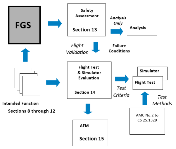
Figure 14-1
14.1 Performance Demonstration (Fault Free) – CS 25.1301
The Certification Plan should identify the specific functionality provided by the FGS. The flight test and/or simulator program will typically assess this functionality under representative operational conditions including applicable aeroplane configurations and a representative range of aeroplane weight, centre of gravity and operational envelope.
The performance of the FGS system in each of its guidance and control modes should be evaluated. The acceptability of the performance of the FGS may be based on test pilot assessment, taking into account the experience acquired from similar equipment capabilities, and the general behaviour of the aeroplane. The level of acceptable performance may vary according to aeroplane type and model. The FGS should be evaluated for its low and high manoeuvring capability. AMC No.2 to CS 25.1329 may provide additional information on FGS test procedures.
The acceptability of mode controls and annunciations, any associated alerts and general compatibility with cockpit displays should be evaluated. The FGS should be free from unexpected disengagement and confusion resulting from changing FGS modes. Additional considerations relating to the assessment of Human Factors is provided in Section 14.5.
Normal performance is considered to be performance during operations well within the aeroplane’s flight envelope and with routine atmospheric and environmental conditions. Normal performance should be demonstrated over a range of conditions that represent typical conditions experienced in operational use.
The FGS should be evaluated to determine the acceptability of the following characteristics:
— The stability and tracking of automatic control elements
— The flyability and tracking of guidance elements
— The acquisition of flight paths for capture modes
— Consistency of integration of modes (Section 12)
Performance should be assessed in the presence of errors that can reasonably be expected in operation (e.g., mis-selection of approach speed).
14.1.2 Rare Normal Performance
Rare normal performance is considered to be performance of the system under conditions that are experienced infrequently by the aeroplane during operational use. These conditions may be due to significant environmental conditions (e.g., significant wind, turbulence, etc.) or due to non-routine operating conditions (e.g., out-of-trim due to fuel imbalance or under certain ferry configurations, or extremes of weight and c.g. combinations). Specific rare normal conditions are discussed below
The test program should assess the FGS performance in more challenging operational environments e.g., winds, wind gradients, various levels of turbulence. Rare environmental conditions may require the FGS to operate at the limits of its capabilities. The intent of the evaluation is to assess the performance of the FGS under more demanding conditions that may be experienced infrequently in-service.
Due to the severity of some environmental conditions, it is not recommended, or required, that the FGS flight evaluations include demonstration in severe and extreme turbulence, or include flights into a microburst. These conditions are more appropriately addressed by simulator evaluation.
The FGS should be evaluated to determine the acceptability of the following characteristics:
— The stability of automatic control elements and ability to resume tracking following any upset
— The flyability of guidance elements and ability to resume tracking following any upset
— The acceptability of mode transitions and overall cockpit system integration.
The implications of continued use of the automatic flight control elements of the FGS in icing conditions should be assessed. Ice accumulation on the aeroplane wings and surfaces can progressively change the aerodynamic characteristics and stability of the aeroplane. Even though the FGS may perform safely under these conditions, its continued use may mask this change which in turn can lead to pilot handling difficulties and potential loss of control, should the autopilot become disengaged (either automatically or manually).
A test program should assess the potential vulnerability of the FGS to icing conditions by evaluating autopilot performance during ice shape tests or during natural icing tests. Sufficient autopilot testing should be conducted to ensure that the autopilot's performance is acceptable.
In general, it is not necessary to conduct an autopilot evaluation that encompasses all weights, centre of gravity positions (including lateral asymmetry), altitudes and deceleration device configurations. However, if the autopilot performance with ice accretion shows a significant difference from the non-contaminated aeroplane, or testing indicates marginal performance, additional tests may be necessary.
FGS performance and safety in icing conditions should be demonstrated by flight test and/or simulation tests, supported by analysis where necessary.
If significant autopilot inputs are required to compensate for the icing conditions, then the acceptability of the indication of a significant out of trim condition should be made and the subsequent response of the aeroplane when the autopilot disengages (manual or automatic) should be determined (Refer to Sections 8.1.2 and 9.3.3).
If the aeroplane is configured with a de-icing system, the autopilot should demonstrate satisfactory performance during the shedding of ice from the aeroplane.
Where degradation is noted which is not significant enough to require changes to the autopilot system or to de-icing/anti-icing systems, appropriate limitations and procedures should be established and presented in the AFM.
If the FGS provides windshear escape guidance, performance demonstration requirements should be conducted consistent with FAA AC 25-12.
14.1.2.3 Indication and Response to an Out of Trim Condition
An assessment should be performed to determine the acceptability of the out of trim annunciation and subsequent response to disengagement (Refer to Section 9.3.3).
14.1.3 Specific Performance Conditions
The following paragraphs identify specific performance conditions requiring evaluation by flight test and/or simulation.
The FGS should be assessed for the acceptability of the low speed protection performance under the following conditions:
— High Altitude Cruise with a simulated engine failure.
— Climb to Altitude Capture at Low Altitude with a simulated engine failure during capture
— Vertical Speed with insufficient climb power
— Approach with speed abuse
14.1.3.2 High-speed Protection
The FGS should be assessed for the acceptability of the high-speed protection performance under the following conditions:
— High altitude level flight with Autothrust function
— High altitude level flight without Autothrust function
— High altitude descending flight with Autothrust function
The objective of the go-around mode (refer to Section 11.3.2) is to quickly change the flight path of the aeroplane from approach to landing to a safe climbout trajectory. The mode has specific utility in low visibility conditions when operations are predicated on a decision altitude/height (DA/H) and a go-around is necessary if visual references are not acquired at the DA/H. Therefore, the assessment of the go-around mode may be conducted in conjunction with the evaluation of the FGS to support low visibility operations, using additional criteria contained in FAA AC 120-28D, AC 120-29A and CS AWO Subparts 2 or 3.
The flight evaluation should be conducted to assess the rotation characteristics of the aeroplane and the performance of the aeroplane in acquiring and maintaining a safe flight path. The acceptability of the operation if contact is made with the runway during the missed approach or balked landing should be established.
A demonstration program should be established that confirms acceptable operation when the following factors are considered:
— Aeroplane weight and CG
— Various landing configurations
— Use of manual thrust or autothrust
— Consequences of thrust de-rates with selection of Go around mode
— An Engine Failure at the initiation of Go-around
— An Engine failure during GA – after go-around power is reached
— Initiation altitude (e.g., in ground effect or not, during flare)
The following characteristics should be evaluated:
— The pitch response of the aeroplane during the initial transition
— Speed performance during aeroplane reconfiguration and climbout
— Integrated autopilot and autothrust operation
— Transition to Missed Approach Altitude
— Lateral performance during an engine failure
Where height loss during a go-around manoeuvre is significant or is required to support specific operational approval, demonstrated values for various initiation heights should be included in the AFM.
14.1.3.4 Steep Approach (Special Authorization)
Typical approach operations include glidepath angles between 2.5 and 3.5 degrees. Application for approval to conduct operations on glidepath angles of greater than 3.5 degrees requires additional evaluation. For such an approval, the FGS flight test and simulator demonstration should include:
— Approach path capture, tracking and speed control
— Recovery of the system from abuse cases e.g. glidepath angle and speed
— Assessment of autopilot disengagement transient
— Demonstration of go-around mode from a Steep Approach
For autopilot use at approach angles greater than 4.5 degrees the applicant is recommended to contact EASA for the applicable Special Condition criteria
14.1.4 Flight Director / HUD Considerations
The guidance aspect of an FGS may be provided by a head down Flight Director (F/D) or by a Head-Up Display (HUD) system. F/D’s can utilize various guidance cues (e.g., cross pointer, single cue, flight path vector, etc.) whilst HUD’s typically use a symbology linked to a flight path vector. The guidance elements may have a fixed aeroplane reference (e.g., the traditional F/D) or may use a moving reference such as a flight path vector. Various new display mediums are evolving (e.g., EVS and SVS) that may integrate guidance elements with situational elements.
The flight test or simulator program should demonstrate that the F/D or HUD guidance elements provide smooth, accurate and damped guidance in all applicable modes, so as to achieve satisfactory control task performance without pilot compensation or excessive workload.
The flight director guidance should provide adequate performance for operations with:
— stability augmentation off
— alternate fly-by-wire control modes (e.g., direct law), if any
— an engine inoperative.
Some pilot compensation may be acceptable for these conditions
Flight directors designed to work with a non-stationary tracking reference (such as a flight path angle or flight path vector which are commonly used with HUD guidance) should be evaluated in conditions which bring these guidance symbols to the field of view limits of the display. Crosswinds, and certain combinations of airspeed, gross weight, centre of gravity and flap/slat/gear configurations might cause such conditions. At these limits, the dynamics of the guidance response to pilot control inputs can differ with potentially adverse affects on tracking performance, pilot compensation and workload.
Movement of the flight director and its tracking reference should also be demonstrated not to interfere with primary instrument references throughout their range of motion. The pilot’s ability to interpret the guidance and essential flight information should not be adversely affected by the movement dynamics or range of motion.
14.1.4.1 Specific Demonstrations for Head-Up Display
These demonstrations are intended to show compliance with the following paragraphs of this AMC:
— Section 8.2 Flight Director Engagement/Disengagement and Indications, with its subparagraphs
— Section 9.2 Flight Guidance Mode Selection, Annunciation and Indication
— Section 9.4 FGS Considerations for Head-Up Displays (HUD)
— Section 10.1 Normal Performance (specifically criteria for flight director guidance)
When the pilot flying (PF) is using the HUD, the HUD is where the pilot is looking for the basic flight information and the pilot is less likely to be scanning the head down instruments. Therefore:
— It should be demonstrated that the location and presentation of the HUD information (e.g., guidance, flight information and alerts/annunciations) does not distract the pilot or obscure the pilot’s outside view. For example, the pilot should be able to track the guidance to the runway without having the view of runway references or hazards along the flight path obscured by the HUD symbology.
— It should be demonstrated that pilot awareness of primary flight information, annunciations and alerts is satisfactory when using any HUD display mode. Some display modes that are designed to minimize “clutter” could degrade pilot awareness of essential information. For example, a “digital-only” display mode may not provide sufficient speed and altitude awareness during high-speed descents.
— It should be demonstrated that the pilot could positively detect cases when conformal symbology is field of view limited.
— Approach mode guidance, if provided, should be satisfactory throughout the intended range of conditions, including at the minimum approach speed and maximum crosswind, with expected gust components, for which approval is sought.
— It should be demonstrated that visual cautions and warnings associated with the flight guidance system can be immediately detected by the pilot flying while using the HUD.
— It should be demonstrated that the pilot flying can immediately respond to windshear warnings, ground proximity warnings, ACAS/TCAS warnings, and other warnings requiring immediate flight control action, such as a go-around, while using the HUD without having to revert to a head down flight display.
In certain phases of flight, it is important from a flight crew coordination standpoint that the pilot not flying (PNF) be aware of problems with the HUD used by the PF. Therefore it should also be demonstrated that the PNF could immediately be made aware of any visual cautions and warnings associated with the HUD for applicable phases of flight.
If approach mode guidance is provided, satisfactory performance should be demonstrated throughout the intended range of operating conditions for which approval is sought e.g. at the minimum approach speed and maximum crosswind, with expected gust components.
If recovery guidance is provided, it should be demonstrated that the pilot could immediately detect and recover from unusual attitudes when using the HUD. Specialized unusual attitude recovery symbology, if provided, should be shown to provide unequivocal indications of the attitude condition (e.g., sky/ground, pitch, roll, and horizon) and to correctly guide the pilot to the nearest horizon. The stroke presentation of flight information on a HUD may not be as inherently intuitive for recognition and recovery as the conventional head down attitude display (e.g., contrasting colour, area fill, shading vs. line strokes). The HUD display design needs to be able to compensate for these differences to provide adequate pilot recognition and recovery cues.
14.1.4.2 Simulator Demonstration for Head-Up Display (HUD)
If a pilot-in-the-loop flight simulation is used for some demonstrations, then a high fidelity, engineering quality facility is typically required. The level of simulator may vary with the functionality being provided and the types of operation being conducted. Factors for validation of the simulation for demonstration purposes include the following:
— guidance and control system interfaces
— motion base suitability
— adequacy of stability derivative estimates used
— adequacy of any simplification assumptions used for the equations of motion;
— fidelity of flight controls and consequent simulated aircraft response to control inputs
— fidelity of the simulation of aircraft performance
— adequacy of flight deck instruments and displays
— adequacy of simulator and display transient response to disturbances or failures (e.g., engine failure, auto-feather, electrical bus switching)
— visual reference availability, fidelity, and delays
— suitability of visibility restriction models such as appropriate calibration of visual references for the tests to be performed for day, night, and dusk conditions as necessary
— fidelity of any other significant factor or limitation relevant to the validity of the simulation.
Adequate correlation of the simulator performance to flight test results should be made.
14.1.5 Flight Crew Override of the Flight Guidance System
A flight evaluation should be conducted to demonstrate compliance with Section 8.4. The flight evaluation should consider the implication of system configuration for various flight phases and operations.
Effect of flight crew override should be assessed by applying an input on the cockpit controller (control column, or equivalent) to each axis for which the FGS is designed to disengage, i.e. the pitch and roll yoke, or the rudder pedals (if applicable).
If the autopilot is designed such that it does not automatically disengage due to a pilot override, verify that no unsafe conditions are generated due to the override per Section 8.4. The evaluation should be repeated with progressively increasing rate of force application to assess FGS behaviour. The effects of speed and altitude should be considered when conducting the evaluation.
If the design of the autopilot provides for multiple channel engagement for some phases of flight that results in a higher override force, these conditions should be evaluated.
The capability of the flight crew to override the autothrust system should be conducted at various flight phases. The evaluation should include an override of the autothrust system with a single hand on the thrust levers while maintaining control of the aeroplane using the opposite hand on the control wheel (or equivalent). This action should not result in an unsafe condition per Section 8.4, either during the override or after the pilot releases the thrust levers. If the autothrust system automatically disengages due to the override, the alerts that accompany the disengagement should be assessed to ensure flight crew awareness.
14.1.5.3 Pitch Trim System Evaluation during an Autopilot Override
The effect of flight crew override during automatic control on the automatic trim systems should be conducted. The pilot should then apply an input to the pitch cockpit controller (i.e., control column or sidestick) below that which would cause the autopilot to disengage and verify that the automatic pitch trim system meets the intent in Section 8.4.
If the system design is such that the autopilot does not have an automatic disengagement on override feature, the pilot should initiate an intentional override for an extended period of time. The autopilot should then be disengaged, with the Quick Disconnect Button, and any transient response assessed in compliance with Section 8.4. The effectiveness and timeliness of any Alerts used to mitigate the effects of the override condition should be assessed during this evaluation.
14.2 Failure Conditions Requiring Validation – CS 25.1309
The Safety Assessment process identified in Section 13 should identify any Failure Condition responses that would require pilot evaluation to assess the severity of the effect, the validity of any assumptions used for pilot recognition and mitigation. The classification of a Failure Condition can vary according to flight condition and may need to be confirmed by simulator or flight test.
This section provides guidance on the test criteria, including recognition considerations, for flight evaluation of these Failure Conditions. In addition, certain probable failures should be demonstrated to assess the performance of the FGS and the adequacy of any applicable flight crew procedures.
AMC No. 2 to CS 25.1329, Flight Testing of Flight Guidance Systems, provides guidance on test methods for particular types of Failure Condition that have been identified by the Safety Assessment.
The Safety Assessment described in Section 13 establishes the FGS Failure Condition for which appropriate testing should be undertaken. Assessment of Failure Conditions has four elements:
— Failure Condition insertion
— Pilot recognition of the effects of the Failure Condition
— Pilot reaction time; i.e., the time between pilot recognition of the Failure Condition and initiation of the recovery
— Pilot recovery
Failure Conditions of the autopilot including, where appropriate, multi-axis failures and automatic-trim failures, should be simulated such that when inserted represents the overall effect of each Failure Condition.
Where necessary, Flight Director Failure Conditions should be validated in accordance with the criteria for the respective phase of flight.
The flight conditions under which the failure condition is inserted should be the most critical (e.g., centre of gravity, weight, flap setting, altitude, speed, power or thrust). If an autothrust system is installed, the tests should be performed with the autothrust system engaged or disengaged whichever is the more adverse case.
The pilot may detect a Failure Condition through aeroplane motion cues or by cockpit flight instruments and alerts. The specific recognition cues will vary with flight condition, phase of flight and crew duties.
a) Hardover – the recognition point should be that at which a pilot operating in non-visual conditions may be expected to recognize the need to take action. Recognition of the effect of the failure may be through the behaviour of the aeroplane (e.g., in the pitch axis by aircraft motion and associated normal acceleration cues and in the roll axis by excessive bank angle), or an appropriate alerting system. Control column or wheel movements alone should not be used for recognition. The recognition time should not normally be less than 1 second. If a recognition time of less than 1 second is asserted, specific justification will be required (e.g. additional tests to ensure that the time is representative in the light of the cues available to the pilot).
b) Slowover – this type of Failure Conditions is typically recognized by a path deviation indicated on primary flight instruments (e.g., CDI, altimeter and vertical speed indicator). It is important that the recognition criteria are agreed with the regulatory authority. The following identify examples of recognition criteria as a function of flight phase:
— En-route cruise – recognition through the Altitude Alerting system can be assumed for vertical path deviation. The lateral motion of the aeroplane may go unrecognised for significant period of time unless a bank angle alerting system is installed.
— Climb and Descent – recognition through increasing/decreasing vertical speed and/or pitch or roll attitude or heading can be assumed.
— On an Approach with vertical path reference - A displacement recognition threshold should be identified and selected for testing that is appropriate for the display(s) and failure condition(s) to be assessed.
NOTE:
(1) For an ILS or GLS approach in a significant wind gradient, a value of 1 dot is considered a reasonable value for crew recognition. In smooth atmospheric conditions with steady state tracking, with the vertical flight path typically maintained at less than a fraction of a needle width, a detection and recognition threshold even below 1/2 dot may be suitable.
(2) For RNAV systems, which do not use dots, some multiple of needle width, related to an established crew monitoring tolerance of normal performance may be appropriate (e.g., x needle widths of deviation on the VNAV scale).
(3) Credit may be taken for excessive deviation alerts, if available.
— On an Approach without vertical path reference – criteria similar to the climb/descent condition can be assumed.
c) Oscillatory – it is assumed that oscillatory failures that have structural implications are addressed under CS 25.302. It can be assumed that the flight crew will disengage the automatic control elements of the FGS that have any adverse oscillatory effect and will not follow any adverse oscillatory guidance. However, if there are any elements of the FGS that can not be disconnected in the presents of an oscillatory Failure Condition, the long term effects on crew workload and the occupants will need to be evaluated.
The pilot reaction time is considered to be dependent upon the pilot attentiveness based upon the phase of flight and associated duties. The following assumptions are considered acceptable:
(a) Climb, Cruise, Descent and Holding – Recovery action should not be initiated until three seconds after the recognition point
(b) Manoeuvring Flight - Recovery action should not be initiated until 1 second after the recognition point
(c) Approach - the demonstration of malfunctions should be consistent with operation in non-visual conditions. The pilot can be assumed to be carefully monitoring the aeroplane performance and will respond rapidly once the malfunction has been recognized. A reaction time of 1 second between recognition point and initiation of recovery is appropriate for this phase of flight.
NOTE:
(i) For the final phase of landing (e.g., below 25 m (80 ft)), the pilot can be assumed to react upon recognition without delay.
(ii) For phases of flight where the pilot is exercising manual control using control wheel steering, if implemented, the pilot can be assumed to commence recovery action at the recognition point.
Pilot recovery action should be commenced after the reaction time. Following such delay the pilot should be able to return the aeroplane to its normal flight attitude under full manual control without engaging in any dangerous manoeuvres during recovery and without control forces exceeding the values given in CS 25.143 (d). During the recovery the pilot may overpower the automatic pilot or disengage it.
For the purpose of determining the minimum height at which the autopilot may be used during an approach, or for height loss assessments, a representative recovery appropriate to the aeroplane type and flight condition should be performed. This manoeuvre should not lead to an unsafe speed excursion to resume a normal flight path. An incremental normal acceleration in the order of 0.5 g is considered the maximum for this type of manoeuvre.
The primary concern for the takeoff phase of flight is the effect of the worst case Failure Condition, identified by the Safety Assessment, on the net flight of the aeroplane after takeoff and the aeroplane’s attitude and speed during climbout. The effects should be evaluated in the pitch up, pitch down and bank as applicable.
If the FGS provides on runway guidance for takeoff, the effect of the failures on that takeoff guidance should be assessed in accordance with CS AWO Subpart 4.
14.2.3 Climb, Cruise, Descent and Holding
Where the Safety Analysis identifies a Failure Condition requiring flight/simulator evaluation with pilot assessment, the height loss should be established in accordance with the method described in the flight test procedures – see AMC No.2 to CS 25.1329, section 4.2.3.3.
Where the Safety Analysis identifies a Failure Condition that has a dynamic effect on the roll control of the aeroplane, the Failure Condition should be introduced at the bank angle for normal operation. The bank angle should not exceed 60 degrees when the pilot recognition and recover times identified above are applied.
A discussion of the operational considerations for approach operations is contained in Section 14.3. This section identifies test criteria to support those considerations. The safety assessment process should identify the demonstration of specific Failure Conditions during the approach.
The fault demonstration process during approach should include the four phases identified in Section 14.2.1. The Failure Condition should be inserted at a safe but representative height. The deviation profile should be identified and applied as indicated in the later sections.
14.2.5.1 Approach with Vertical Path Reference
Approach with vertical path reference includes xLS and RNAV operations.
a) xLS (ILS, MLS, GLS)
ILS and MLS operations are typically conducted on instrument approach procedures designed in accordance with United States TERPS or ICAO PANS-OPS criteria, or equivalent. These criteria together with ICAO Annex 14 are generally intended to take into account obstacles beneath a reference obstacle identification surface. It is expected that the same or equivalent criteria will be applied to GLS operations. Hence, in assessing the implication of the effect of failures during autopilot operations a reference 1:29 slope penetration boundary has been applied against the deviation profile to identify an appropriate altitude for continued autopilot operation. The 1:29 slope has been found to provide an acceptable margin above obstacles on an approach.
The worst case Failure Condition identified by the Safety Assessment (see Section 13.4) should be demonstrated against the deviation profile criteria and a Minimum Use Height (MUH) established (See AMC No.2 to CS 25.1329, Section 4.2.3.2).
b) RNAV
For RNAV coupled approach operations, a vertical flight path similar to an xLS flight path will be used (e.g., 3o path starting 15 m (50 ft) above the threshold). However, due to sensor characteristics it is assumed that RNAV operations will be conducted with a DA(H) or MDA(H) that is higher than an equivalent MUH on an xLS approach to the same runway. Further, for this type of operation it should be noted that the MUH is always in the visual segment of the approach, where it is assumed that the failure recognition and recovery are conducted with the pilot having established outside visual reference.
In order to derive only one MUH value for simplicity of use, it is assumed that the effects of failure on the autopilot in RNAV operation are no worse than for the xLS operation, and no further determination or demonstration is required. However, the applicant should show that due account has be taken in the Safety Assessment of the differences between the RNAV and xLS inputs to the autopilot (e.g. barometric altitude input, FMS position and guidance commands, and their failure effects). If these effects can be bounded or otherwise reconciled, then the xLS demonstrated MUH might also be considered applicable to RNAV operations.
If these effects cannot be bounded or accounted for within those for the xLS operation, the MUH should be determined in accordance with an Approach Without Vertical Path Reference – see below.
14.2.5.2 Approach Without Vertical Path Reference
For an approach without vertical path reference (e.g., VOR, NDB, localizer only) the FGS mode of operation is typically vertical speed/flight path angle (i.e. a cruise mode). The worst case Failure Condition for this type of mode should be demonstrated in the approach configuration, and an appropriate height loss established in accordance with the method described in AMC No.2 to CS 25.1329, Section 4.2.3.3.
In support of an approval to use the FGS on glidepath angles of greater than 3.5 degrees (see Section 14.1.3.4) an assessment should be made of the effects of failure conditions for this type of operation. For the use of autopilot, an appropriate MUH should be established in accordance with the deviation profile method described in Section 14.2.5. For this assessment, the obstacle plane associated with a nominal 3-degree glidepath angle (1:29 slope) should be adjusted according to the maximum approach angle, for which approval is sought.
The following are failure conditions that should be considered as part of the FGS evaluation program:
— Engine Failure during approach - continue approach to DA(H)/MDA(H)
— The effect of potential fuel imbalance
— Aeroplane System Failures (as necessary – requiring specific flight evaluation), e.g.,
— Hydraulics
— Electrical
— Flight Controls
— FGS related Sensors
The probability of failure of a FGS element to disengage when the quick disengagement control is operated should be shown to be acceptable by the Safety Analysis process. If credit is to be taken for acceptable continued manual operation with the FGS elements remaining engaged i.e. without operating any of the other disengagement controls, then a flight demonstration should be conducted though approach, landing and rollout.
14.3 Criteria Supporting the Operational Use of an Autopilot
The criteria contained in this section are intended to identify how the functional capability of the FGS, established during the certification, can be utilized to support typical flight operations. The criteria are based on experience gained from certification programs and functionality provided by traditional systems. A FGS providing non-traditional functionality, using new or novel technology, and/or implementation techniques, may require additional criteria to be established.
14.3.1 Autopilot Operations in close proximity the ground
The minimum engagement point for the autopilot after takeoff and the minimum use of the autopilot during approach should take into consideration the effect of:
— Failures and their effects (i.e., Failure Conditions),
— Fault-free performance,
— Any specific operational considerations and/or mitigation.
During low visibility operations, multiple redundant autopilot channels may be used and the effect of any autopilot failures on the flight path may be eliminated, or substantially minimized, by the protection provided be that redundancy. The following considerations apply primarily to single channel operations where performance or integrity aspects may require further consideration. See also Section 13.5.2, which identifies specific considerations relating to autopilot operations close to the ground in the presence of failures.
14.3.1.1 Autopilot Engagement Altitude or Height after Takeoff – Failure Effects
The potential deviation of the aeroplane from the desired flight path due to the effect of a Failure Condition may necessitate delaying the engagement of an autopilot to an acceptable height above the departure runway.
To support this determination, if an autopilot Failure Condition, or Failure Conditions, are identified that will cause a significant deviation below the intended vertical flight path, the worst-case deviation profile should be identified. This profile and the recovery of the aeroplane should not result in penetration of the net flight path as defined in CS 25.115. If the Failure Condition(s) has a neutral effect on the flight path but has implications for speed control during takeoff, the acceptability of cues for the flight crew detection of the condition should be made. The effect of any Failure Condition relating to the bank angle of the aeroplane should also be assessed. In all of the above, account should be taken of operating the aeroplane at the WAT limit.
The minimum engagement height will typically be established based on the greater of the following considerations:
— The lowest altitude or height where the flight crew could reasonably be assumed to engage the autopilot. Consideration should be given to normal flight crew tasks during rotation and lift-off (typically 30 m (100 ft) or greater).
— Any allowance for the acceptability of the performance of the autopilot during the basic engagement/mode transition.
— The lowest altitude or height consistent with the response of the aeroplane to any identified autopilot Failure Condition(s).
— Activation of stall identification system (e.g. stick pusher) armed (if installed).
If the response to the worst-case failure condition causes a significant transition below the intended vertical flight path, the deviation information should be provided in the AFM.
14.3.1.2 Autopilot Engagement during Approach
The potential deviation of the aeroplane from the desired flight path due to the effect of a Failure Condition may necessitate the disengagement of an autopilot at an appropriate height on the approach to landing.
The operational minimum engagement height will be established based on the following considerations:
— the altitude or height at which the performance of the automatic control is no longer acceptable,
— the lowest altitude or height consistent with the response of the aeroplane to a subsequent autopilot failure,
— any specific operational consideration.
The following paragraphs provide assessment criteria for operations that have guidance to the runway threshold, and for those that do not.
14.3.1.2.1 Approach with Vertical Path Reference – Failure Effects
Approaches with vertical path reference can include xLS (i.e., ILS, MLS and GLS) or RNAV. Operations using xLS, can be assumed to be conducted with respect to a flight path prescribed or established as an integral part of navigation service provided by the State of the airport. RNAV approach operations will be conducted using an onboard database that provides a navigation flight path to the runway.
The operational consideration for this type of operations relates an assessment of the adequacy of continued use of the autopilot in maintaining the desired vertical flight path. Considerations include the lowest altitude consistent with the response of the aeroplane to an autopilot failure.
To support this determination, if an autopilot Failure Condition, or Failure Conditions, is identified that causes a significant transition below the intended vertical flight path, the worst-case deviation profile should be identified using the method identified in Section 14.2.5.1. If the Failure Condition(s) has a neutral effect on the flight path, the acceptability of cues for the flight crew detection of the condition should be made. The effect of any Failure Condition relating to the bank angle of the aeroplane should be assessed.
For the purpose of the airworthiness assessment, the vertical flight path an xLS and RNAV approach can be assumed to be a flight path of three degrees that passes through the runway threshold at an altitude of 15 meters (50 ft). Considerations for steep approaches are provided in a preceding section.
The vertical flight path control for an xLS approach will be made with reference to the path defined by the navigation service. The RNAV vertical flight path will typically be conducted with reference to barometric altitude. An appropriate adjustment to the minimum use height may be appropriate to take into account the vertical accuracy of RNAV operations.
NOTE: Any operational considerations such as temperature effect compensation should be considered as part of the operational authorization.
The Minimum Use Height can be determined using the method identified in AMC No.2 to CS 25.1329, Section 4.2.3.2.
14.3.1.2.2 Approach without Vertical Path Reference
Flight operations with no vertical path reference are conducted with an appropriate visual segment for final approach path. In the interest of providing appropriate automatic control to assist in a stabilized approach, the minimum use of the autopilot should be consistent with the performance needed for the descent (e.g., vertical speed/flight path angle) and the pilot detection and recovery from an autopilot failure.
To support this determination, if an autopilot Failure Condition, or Failure Conditions, is identified that causes a significant transition below the intended vertical flight path, the worst-case deviation profile should be identified. If the Failure Condition(s) has a neutral effect on the flight path but has implications for speed control during takeoff, the acceptability of cues for the flight crew detection of the condition should be made. The effect of any Failure Condition relating to the bank angle of the aeroplane should be assessed.
For FGS that are failure protected (i.e., fail passive), the minimum engagement height will typically be no lower than 15 m (50 ft) above runway elevation. However, when determining this limitation, account should be taken of the handling task presented to the pilot when regaining manual control, especially in limiting crosswind conditions.
For FGS that are not failure protected (i.e., not fail-passive), the demonstrated minimum use height will typically be established based on the greater of the following considerations:
a. 15 m (50 ft) above runway elevation
b. Two times the Height Loss for the aeroplane as a result of any identified autopilot Failure Condition(s) using the method identified in AMC No.2 to CS 25.1329, Section 4.2.3.3.
For the purposes of this AMC, circling approaches may be considered to have three visual segments associated with the approach; a segment at or above the minimums prescribed by the procedure that parallel the runway in the opposite direction of the landing runway, a turning segment to align with the runway that can be level or partially descending, and a final descending segment to landing. Operationally, the autopilot may remain engaged even after leaving the minimum altitude (MDA(H)) for safety and flight crew workload relief reasons. This operational procedure should be balanced against unacceptable performance or failure characteristics. As this procedure is in the visual segment, no specific constraints for the use of the autopilot are considered necessary for this phase of flight unless specific unacceptable performance or failure characteristics related to circling approach are identified during the certification program.
14.3.2 Climb, Cruise, Descent, and Holding
The value of the use of the autopilot in providing flight crew workload relief in climb, cruise, descent and holding phases of flight should be balanced against the failure characteristics of the autopilot. No specific constraints for the use of the autopilot are considered necessary for these phases of flight unless specific unacceptable performance or failure characteristics are identified during the certification program, related to climb, cruise, descent or holding.
No specific constraints for the use of the autopilot are considered necessary for manoeuvring flight unless unacceptable performance or failure characteristics are identified during the certification program. Section 14.2.4 provides assessment criteria for manoeuvring flight for autopilot failures.
14.4 Automatic Disengagement of the Autopilot
Automatic disengagement of the FGS will occur for several reasons such as system failures, sensor failures, unusual accelerations, etc. The automatic disengagement characteristics of the FGS should be investigated throughout the flight envelope. These disengagement cases should be analysed to determine the ones requiring demonstration during the test program. For each disengagement, the transients, warnings, and pilot workload for recovery should be evaluated, and compliance with CS 25.1329 (d) and (e) should be verified. The use of simulation is recommended for all conditions that are expected to result in significant transients.
14.5 Assessment of Human Factors Considerations
The evaluation, demonstration and testing should assess the acceptability of the human-machine interface with the FGS and the potential for flight crew errors and confusion concerning the behaviour and operation of the FGS, based on the criteria described in earlier Sections.
The evaluation of normal and non-normal FGS operations should include the representative range of conditions in terms of crew mental or physical workload, required crew response timeliness, or potential for confusion or indecision. The set of test cases should represent operationally relevant scenarios and the assumptions about pilot training and skill level should be documented.
Flight evaluation during certification is a final assessment and is intended to validate the design. Prior evaluations are typically conducted in a variety of ways and at different levels of fidelity in order to finalize the design. These may include:
— Engineering evaluations and task analyses, including cognitive and physical tasks;
— Mock-up evaluations and demonstrations;
— Part-task evaluations and demonstrations;
— Simulator evaluations, demonstrations, and tests; and
— Engineering flight evaluations, demonstrations, and tests.
The data and/or experience from such evaluations may be useful for credit to establish FGS compliance with regulations having human factors considerations. In some cases, certification credit or demonstration of compliance using simulations cannot be granted due to inability to find simulation conformity. In such cases, certification authorities may consider that less flight testing may be required to show compliance if the simulation evaluations have added confidence with respect to the reduced potential for crew error and confusion and other human factors attributes of the pilot/FGS interface. Also, applicants have successfully used comparisons to previously certificated designs to obtain such credit (although such credit is not assured). Additional testing may be warranted, e.g., for new FGS flight crew interface designs or functions.
In many cases the evaluation, demonstration and test scenarios, including failures and environmental events, will determine whether the data should be obtained in simulation or in flight, because of safety considerations or unavailability of the necessary environmental conditions. In some of these cases a very high fidelity simulation will be needed. In addition to the simulation validation considerations identified in Section 14.1.4.2, the simulation used may need to include the following features, depending on the functionality of the FGS:
— Physical implementation of flight deck controls, displays, indicators and annunciators for all flight crew positions that are relevant to the objectives of the evaluation.
— Adequate emulations of relevant equipment (hardware and software function, including capability to introduce failures) should be incorporated in the simulation.
— Weather simulation including gusts, turbulence, windshear and visibility.
— Representation of the operational environments, including interaction with air traffic services, day/night operations, etc, as relevant to the functions and pilot tasks being evaluated
— Data collection capabilities
Simulator evaluations and tests are intended to generate objective and/or subjective data. It may not always be possible or necessary to obtain quantifiable measurements of flight crew performance, even with high fidelity flight or simulation evaluation, demonstration, or test scenarios. In these cases, evaluation procedures should be based on the use of structured, subjective methods such as rating scales, questionnaires and/or interviews. When there is dependence on this type of data, evaluations should consider multiple data collection techniques with an appropriate number of pilot evaluators.
In order to provide sound evaluations, pilots should be trained appropriately on the FGS system operation and procedures. They should also have experience in the kinds of operation and aircraft types for which the FGS is intended, be familiar with the intended function of the FGS, its operational and design philosophy, and how this philosophy fits with the overall flight deck and its operational and design philosophy.
Rationale should be provided for decisions regarding new or unique features in a design. It should be confirmed that the data resulting from the evaluations support acceptability of any new or unique features.
The certification planning documentation should describe the means to show compliance of the Human Factors-related considerations of the FGS, with this AMC.
15 AEROPLANE FLIGHT MANUAL (AFM)
The following sections provide guidance on material to be provided in the Aeroplane Flight Manual (AFM) to ensure that the appropriate information related to FGS operation is translated into air carrier operations. For additional guidance, note that AMC 25.1581 addresses requirements of the AFM for Large Aeroplanes and distinguishes between those aircraft that are used in Commercial Air Transportation and those that are not.
The terminology used in the AFM should be consistent with the intended operational use.
Appropriate AFM information related to low-visibility operations is addressed in CS-AWO Subparts 1-4.
15.1 Information Supporting Operational Use of the Autopilot
The airworthiness certification process will assess the effect of autopilot Failure Conditions as identified in Sections 13 and 14. If a specific Minimum Use Height (MUH) is necessary, then the height should be provided in the Limitations section of the AFM. If the design is such that the effects of Failure Condition(s) do not require establishment of a MUH, then the pertinent deviation profile or height loss information should be provided in the Normal or Non-normal section of the AFM, as applicable.
If MUH or a Height Loss value is applicable, it should be specified as follows:
(a) Takeoff - Autopilot Engagement Altitude or Height.
NOTE: If minimum engagement altitude(s) or height(s) are not specified, then “maximum displacement deviation” information from a pertinent takeoff flight path and approach profile should be provided in the AFM Normal Procedures section, or in the associated Flight Crew Operation Manuals (FCOM).
(b) Cruise – Height Loss
(c) Approach - MUH or Height Loss
i) Approach – with Vertical Path Reference
— the MUH should be determined based on clearance above a 1:29 plane using the Deviation Profile Method.
ii) Approach – without Vertical Path Reference
— the Height Loss should be determined using the Height Loss Method
The Limitations section of the AFM presents those FGS operating limitations appropriate to the aeroplane model as established in the course of the type certification process, and as necessary (Ref. CS 25.1581(a)(1) and CS 25.1583). FGS operational limitations (should any exist) should specify, any configuration/envelope restrictions, if and as applicable.
15.3 Non-normal/Emergency Procedures
The AFM should include Non-normal or Emergency procedures appropriate to the FGS identified during the certification program (Ref. CS 25.1581(a)(1), CS 25.1585(a)(2) and CS 25.1585(a)(3)).
In lieu of specification of minimum engagement altitude(s) or height(s) (see Section 15.1 above)), the AFM may alternately specify “maximum displacement deviations” from a specified takeoff flight path, or from a specified approach profile. This information may be based on typical departure or approach flight paths suited for the aircraft type and for failure conditions that are determined applicable to the type of FGS system and modes suitable for use.
The flight manual should include any necessary procedures for the use of the flight guidance system in icing conditions (including severe icing conditions). In particular, the procedures should include any necessary changes in operating speeds required either operationally or as a result of relevant design features of the speed protection function of the FGS; e.g., variations in minimum speeds as a function of de/anti-icing system selection; speed increments during approach and landing in turbulence.
15.4.1 Aircraft with Published Flight Crew Operation Manuals
The AFM’s for aircraft for which the manufacturer has published a FCOM should contain essential information on normal operating procedures that are considered “peculiar” to the operation of the FGS for the aircraft type or are otherwise necessary for safe operation (Ref. CS 25.1581(a)(2) and CS 25.1585(a)(1)). FGS description and integration with the overall flight deck design philosophy; specification and operational procedures that are normally associated with flight guidance systems should be made available for inclusion in the FCOM.
If applicable, a FCOM may contain the “maximum displacement deviation” information described in Section 15.1, above, in either numeric or graphic form.
15.4.2 Aircraft without Published FCOM’s
For aircraft that rely on the AFM as the sole operating manual, the AFM must contain operating information sufficient for flight crew reference (Ref. CS 25.1581(a)(2)). FGS description and integration with the overall flight deck design philosophy, specification and operational procedures that are normally associated with flight guidance systems should be made available so that an appropriately trained flight crew may operate the FGS under normal conditions.
[Amdt 25/4]
[Amdt 25/11]
[Amdt 25/12]
[Amdt 25/16]
[Amdt 25/18]
[Amdt 25/26]
Appendix A – Safety Assessment
ED Decision 2007/020/R
This section provides material that may be useful in supporting the safety assessment activities identified in Section 13.
A2 Identification of Failure Conditions
The following “failures” should be considered for applicability when establishing Failure Conditions as indicated in Section 13:
— Loss of autopilot in single or multiple axes
— Loss of guidance in single or multiple axes
— Loss of thrust control
— Partial loss or degradation of autopilot function
— A failure resulting in unintended autopilot commands in a single axis or multiple axes simultaneously (e.g., hardover, slowover, and oscillatory failure modes)
— A failure resulting in unintended guidance commands in a single axis or multiple axes
— A failure resulting in unintended thrust control
— A sustained out-of-trim condition with the autopilot engaged without a warning
— An autopilot disengagement in an out-of-trim condition
— Autopilot disengagement without a warning
— Inability to disengage the autopilot or autothrust function
— Un-commanded engagement of an autopilot or autothrust
— Jamming or loading of primary flight controls
— Un-intended thrust asymmetry
A typical Failure Condition statement may be of the form:
‘{Failure}’ during ‘{Phase of Flight}’ that ‘{Effect}’ when ‘{Mitigation Consideration}’
Failure Conditions may result from failures within the FGS or from failure associated with aircraft interfacing systems or components (e.g., navigation receivers, attitude heading reference systems, flight management systems, hydraulics, electrical systems, etc.).
A3 Considerations when Assessing the Severity of Failure Condition Effects
The Failure Condition definition is complete (as defined in AMC 25.1309) when the effects resulting from “failure” are identified. A complete definition of the Failure Condition and its effect will then support the subsequent Failure Condition classification.
When assessing the effect that results from a failure, the following items should be considered for various phases of flight:
— The impact of the loss of control, or unintended control, on the structural integrity of the aeroplane as a result of simple loading or as a result of excitation of aerodynamic or structural modes, both at the time of occurrence and while the flight continues.
— Implications of the aeroplane response in terms of attitude, speed, accelerations, flight path, and the impact on the occupants and on flight crew performance.
— Degradation in the stability or other flying qualities of the aeroplane.
— The duration of the condition.
— The aircraft configuration.
— The aircraft motion cues that will be used by the flight crew for recognition.
— Availability, level, and type of alerting provided to the flight crew.
— Expected flight crew corrective action on detection of the failure.
Failure Conditions may include the following characteristics:
— “Hardover” effects - typically considered to significant and are readily detectable by the flight crew based on the resulting aircraft motion or guidance cues.
— “Slowover” effects - typically not readily detected by the flight crew. The effect may involve departures from intended flight path that are not initially detectable by aircraft motion alone, and may only be detectable by motion cues when a significant flight path deviation has occurred or by the provision of an appropriate flight crew alert.
— “Oscillatory” effects – typically a repetitive motion or guidance condition not related to intended guidance or control. The magnitude, period and duration of the condition and any mitigation considerations will determine the final effect.
— “Loss of” effects – typically the removal of control, guidance or functionality that may have an immediate effect or may not be immediately apparent to the flight crew.
Section 14 provides guidance on crew recognition considerations.
A4 Failure Condition Classification
A4.1 Catastrophic Failure Conditions
The following effects have been assessed Catastrophic in previous aeroplane certification programs:
— A load on any part of the primary structure sufficient to cause a structural failure preventing safe flight and landing (Refer to CS 25.302).
— Unrecoverable loss of flight path control.
— Exceedance of VDF/MDF.
— Flutter or vibration that causes a structural failure preventing safe flight and landing (Refer to CS 25.302).
— A temporary loss of control (e.g., stall) where the flight crew is unable to prevent contact with obstacles or terrain.
— Deviations in flight path from which the flight crew are unable to prevent contact with obstacles, terrain, or other aircraft.
A4.2 Hazardous Failure Conditions
The following effects have been assessed Hazardous in previous aeroplane certification programs:
— Exceedance of airspeed halfway between VMO and VDF or a Mach number halfway between MMO and MDF.
— A stall, even if the flight crew is able to recover safe flight path control.
— A load factor less than zero.
— Bank angles of more than 60 degrees en route or more than 30 degrees below a height of 300 m (1000 ft). above an applicable airport elevation.
— Degradation of the flying qualities of the aeroplane that excessively increases flight crew workload.
— Failure that could result in a RTO and high speed overrun (e.g., 110 km/h (60 kt)).
— A flight path deviation that requires a severe manoeuvre to prevent contact with obstacle, terrain or other aircraft.
NOTE: Severe manoeuvre includes risk of serious injury or death of a small number of occupants.
The following effects have been assessed Major in previous aeroplane certification programs:
A flight path deviation, a required recovery manoeuvre, which may result in passenger injuries (e.g., consideration should be given to phases of flight where the occupants may reasonably be moving about the aeroplane or be serving or consuming hot drinks).
Degradation of the flying qualities of the aeroplane that significantly increase flight crew workload.
[Amdt 25/4]
AMC No.2 to CS 25.1329 Flight Testing of Flight Guidance Systems
ED Decision 2007/020/R
Some aspects of a Flight Guidance System (FGS) design may be validated by laboratory testing or by simulation, other aspects may necessitate test pilot expertise and subjective judgment in a representative aircraft environment. The purpose of this AMC is to provide FGS flight test procedures without specifying the test means to be used, i.e. actual aircraft or representative flight simulator.
A flight test program should be established that confirms the performance of the FGS for the modes of operation and the operational capabilities supported by its design. The operational implications of certain failures and Failure Conditions may require flight evaluation. The pilot interface with FGS controls and displays in the cockpit should also be assessed.
The scope of the flight demonstration program will be dependent on the operational capability being provided including any new and novel features. Early coordination with the regulatory authorities is recommended to reduce certification risks associated with the flight demonstration program.
The intent of the flight demonstration program is to confirm that the operation of the FGS is consistent with its use for the intended flight operations of the aeroplane type and configuration.
The modes of the FGS should be demonstrated in representative aeroplane configurations and under a representative range of flight conditions.
The following are specific test procedure that can assist in that demonstration program. The procedures should be read in conjunction with Sections 10, 11 and 14 of AMC No. 1 to CS 25.1329.
Protection feature are included in the design of an FGS to assist the flight crew in ensuring that boundaries of the flight envelope or operational limits are not exceeded leading to an unsafe condition. The means to alert the flight crew to a condition or for the system to intervene to preclude the condition may vary but certain operational scenarios can be used to assess the performance of the system in providing the protection function. The following procedures can be used to evaluate the protection functions of an FGS.
The low speed protection feature in an FGS is intended to prevent loss of speed to an unsafe condition (Refer to AMC No. 1 to CS 25.1329 – Section 10.4.1). This may be accomplished by a number of means but should be evaluated under a number of scenarios.
There are four cases that should be considered when evaluating when the Low Speed Protection function of a FGS:
1. High Altitude Cruise Evaluation.
(a) At high altitude at normal cruise speed, engage the FGS into an Altitude Hold mode and a Heading or LNAV mode.
(b) Engage the autothrust into a speed mode.
(c) Manually reduce one engine to idle thrust.
(d) As the airspeed decreases, observe the FGS behaviour in maintaining altitude and heading/course.
(e) When the Low Speed Protection condition becomes active, note the airspeed and the associated aural and visual alerts including possible mode change annunciations for acceptable operation.
2. Altitude Capture Evaluation at Low Altitude.
(a) At about 1000 m (or 3000 ft) MSL and 460 km/h (or 250 kt), engage the FGS into Altitude Hold and a Heading or LNAV mode.
(b) Engage the autothrust into a speed mode.
(c) Set the Altitude Pre-selector to 2500 m (or 8000 ft) MSL.
(d) Make a flight level change to 2500 m (or 8000 ft) with a 460 km/h (250 kt) climb at maximum climb power.
(e) When the FGS first enters the altitude capture mode, retard an engine to idle power.
(f) As the airspeed decreases, observe the aeroplane trajectory and behaviour.
(g) When the Low Speed Protection condition becomes active, note the airspeed and the associated aural and visual alerts including possible mode change annunciations for acceptable operations.
3. High Vertical Speed Evaluation.
(a) Engage the FGS in Vertical Speed Mode with a very high rate of climb.
(b) Set the thrust to a value that will cause the aeroplane to decelerate at about 1.8 km per second (1 knot per second).
(c) As the airspeed decreases, observe the aeroplane trajectory and behaviour.
(d) When the Low Speed Protection condition becomes active, note the airspeed and the associated aural and visual alerts including possible mode change annunciations for acceptable operation.
4. Approach Evaluation.
(a) Conduct an instrument approach with vertical path reference.
(b) Couple the FGS to the localizer and glideslope (or LNAV/VNAV, etc.).
(c) Cross the Final Approach Fix/Outer Marker at a high-speed (approximately Vref + 74 km/h (40 kt)) with the thrust at idle power until low speed protection activates.
(d) As the airspeed decreases, observe the aeroplane trajectory and behaviour.
(e) When the Low Speed Protection condition becomes active, note the airspeed and the associated aural and visual alerts including possible mode change annunciation for acceptable operation.
(f) Note the pilot response to the alert and the recovery actions taken to recover to the desired vertical path and the re-capture to that path and the acceleration back to the desired approach speed.
NOTE: If the FGS remains in the existing mode with reversion to Low Speed Protection, the FGS should provide a suitable alert to annunciate the low speed condition. In this case, note the pilot response to the alert and the recovery actions taken to maintain the desired vertical path and to accelerate back to the desired approach speed.
The high-speed protection feature in an FGS is intended to prevent a gain in airspeed to an unsafe condition (Refer to AMC No. 1 to CS 25.1329 – Section 10.4.2). This may be accomplished by a number of means but should be evaluated under a number of scenarios.
There are three cases that should be considered when evaluating the High-speed protection function of a FGS:
1. High Altitude Level Flight Evaluation with Autothrust function
(a) Select Autothrust Off (if an automatic wake-up function is provided; otherwise, select Autothrust on).
(b) Engage the FGS in altitude hold.
(c) Select a thrust level that will result in acceleration beyond VMO/MMO.
(d) As the airspeed increases, observe the behaviour of the High-speed protection condition and any autothrust reactivation and thrust reduction, as applicable.
(e) Assess the performance of the FGS to control the airspeed to VMO/MMO, or other appropriate speed.
2. High Altitude Level Flight Evaluation without Autothrust function
(a) Select a thrust value that will result in acceleration beyond VMO/MMO.
(b) As the airspeed increases, observe the basic aeroplane overspeed warning activate between VMO + 1 and VMO + 11 km/h (6 kt).
(c) Observe the high-speed protection condition become active as evidenced by the unique visual alert and note possible FGS mode change.
(d) Maintain the existing thrust level and observe the aeroplane depart the selected altitude.
(e) After sufficient time has elapsed to verify and record FGS behaviour has elapsed, reduce the thrust as necessary to cause the aeroplane to begin a descent.
(f) Observe the FGS behaviour during the descent and subsequent altitude capture at the original selected altitude.
3. High Altitude Descending Flight Evaluation with Autothrust function
(a) Select Autothrust Off (with automatic wake-up function) with thrust set to maintain airspeed 10% below VMO/MMO with the FGS engaged in altitude hold.
(b) Select vertical speed mode that will result in acceleration beyond VMO/MMO.
(c) As the airspeed increases observe the autothrust function reactivate and reduce thrust towards idle.
(d) Observe the activation of FGS high-speed protection condition.
(e) Observe the reduction in pitch.
GENERAL NOTE: If the FGS remains in the existing mode with reversion to High Speed Protection, the FGS should provide a suitable alert to annunciate the high-speed condition. In this case, note the pilot response to the alert and the recovery actions taken to maintain the desired vertical path and to decelerate back to the desired speed.
3. Environmental Conditions
Some environmental conditions have created operational problems during FGS operations. It should be the objective of the flight demonstration program to expose the FGS to a range of environmental conditions as the opportunity presents itself. These include winds, windshear, mountain-wave, turbulence, icing, etc. However, some specific test conditions may have to be created to emulate operational conditions that are not readily achieved during normal flight test.
The accumulation of ice on the wing and airframe can have an effect on aeroplane characteristics and FGS performance. FGS operations may mask the onset of an aeroplane configuration that would present the pilot with handling difficulties when resuming manual control, particularly following any automatic disengagement of the FGS.
During the flight test program the opportunity should be taken to evaluate the FGS during natural icing conditions including the shedding of the ice, as applicable.
It is recommended that the opportunity should be taken to evaluate the operation of the FGS during basic aeroplane evaluation with ‘ice shapes’.
The following conditions should be considered for evaluating FGS performance under ‘icing conditions’:
(a) "Holding ice" as defined by CS-25 Appendix C
(b) Medium to light weight, symmetric fuel loading
(1) High lift devices retracted configuration:
Slow down at 1.8 km per second (1 knot per second) to automatic autopilot disengage, stall warning or entry into speed protection function.
Recovery should be initiated a reasonable period after the onset of stall warning or other appropriate warning. The aeroplane should exhibit no hazardous characteristics.
(2) Full Instrument Approach:
If the autopilot has the ability to fly a coupled instrument approach and go-around, it should demonstrate the following:
(i) Instrument approach using all normal flap selections.
(ii) Go-around using all normal flap selections.
(iii) Glideslope capture from above the glidepath.
(3) If the aeroplane accretes or sheds ice asymmetrically it should be possible to disengage the autopilot at any time without unacceptable out of trim forces.
(4) General manoeuvrability including normal turns, maximum angle of bank commanded by the FGS in one direction and then rapid reversal of command reference to the maximum FGS angle of bank in the other direction.
The test method for most Failure Conditions will require some type a fault simulation technique with controls that provide for controlled insertion and removal of the type of fault identified as vulnerability. The insertion point will typically be at a major control or guidance point on the aeroplane (e.g., control surface command, guidance command, thrust command).
The implication of the effect of the Failure Condition on various flight phases should be assessed and the demonstration condition established. This assessment should identify the parameters that need to be measured and the instrumentation required.
The role of any monitoring and alerting in the evaluation should be identified.
The alertness of the crew to certain aeroplane response cues may vary with phase of flight and other considerations. Guidance on this is provided below.
The ‘success criteria’ or operational implications should be identified and agreed with the regulatory authority prior to the conduct of the test. Guidance on this is provided below.
4.2 Fault Recognition and Pilot Action
The Safety Assessment process may identify a vulnerability to the following types of Failure Condition:
— hardover
— slowover
— oscillatory
The various types of effect will cause differing response in the aeroplane and resultant motion and other cues to the flight crew to alert them to the condition. The flight crew attention may be gained by additional alerting provided by systems on the aeroplane. The recognition is then followed by appropriate action including recovery.
The assessment of the acceptability of the Failure Condition and the validation of the Safety Assessment assumptions are complete when a stable state is reached as determined by the test pilot.
The following paragraphs provide guidance for specific phases of flight.
This material addresses the use of an FGS after rotation for takeoff.
Section 13 of AMC No. 1 to CS 25.1329 identifies the key considerations for this phase of flight to be the effect on the net flight path and the speed control after lift-off. Automatic control is not typically provided for the takeoff roll. It may however be selected soon after lift-off. Failure Conditions may be introduced with this engagement.
For the initial lift-off through flap retraction, it can be assumed that the flight crew is closely monitoring the aeroplane movements and a maximum crew response time after recognition would be 1 second.
4.2.2 Climb, Cruise, Descent and Holding and Manoeuvring
The demonstration of applicable failure conditions during these phases of flight would include the potential for occupants to be out of their seats and moving about the cabin.
There are two types of approach operations to consider – an approach with and without vertical path reference. The approach with vertical path reference will be assessed against ground-based criteria using a deviation profile assessment. A height loss assessment is used for approaches without vertical path reference.
4.2.3.1 Fault Demonstration Process
The worst-case malfunction has first to be determined, based on factors such as:
i) Failure Conditions identified by the system safety assessment.
ii) System characteristics such as variations in authority or monitor operation.
iii) Mitigation provided by any system alerts.
iv) Aircraft flight characteristics relevant to failure recognition.
Once the worst-case malfunction has been determined, flight tests of the worst-case malfunction should be flown in representative conditions (e.g. coupled to an ILS), with the malfunction being initiated at a safe height. The pilot should not initiate recovery from the malfunction until 1 second after the recognition point. The delay is intended to simulate the variability in response to effectively a “hands off” condition. It is expected that the pilot will follow through on the controls until the recovery is initiated.
4.2.3.2 Assessment – Approach with Vertical Path Reference
Figure 1 provides a depiction of the deviation profile method. The first step is to identify the deviation profile from the worst-case malfunction. The next step is to ‘slide’ the deviation profile down the glidepath, until it is tangential to the 1:29 line or the runway. The Failure Condition contribution to the Minimum Use Height may be determined from the geometry of the aircraft wheel height determined by the deviation profile, relative to the 1:29 line intersecting a point 4.5 m (15 ft) above the threshold. The method of determination may be graphical or by calculation.
NOTE: The Minimum Use Height is based on the recovery point because:
i) It is assumed that in service the pilot will be “Hands off” until the autopilot is disengaged at the Minimum Use Height in normal operation.
ii) The test technique assumes a worst case based on the pilot being “Hands off” from the point of malfunction initiation to the point of recovery.
iii) A failure occurring later in the approach than the point of initiation of the worst case malfunction described above is therefore assumed to be recovered earlier and in consequence to be less severe.
4.2.3.3 Assessment – Approach without Vertical Path Reference
Figure 2 provides a depiction of the height loss method. A descent path of three degrees, with nominal approach speed, should be used unless the autopilot is to be approved for significantly steeper descents. The vertical height loss is determined by the deviation of the aircraft wheel height relative to the nominal wheel flight path.
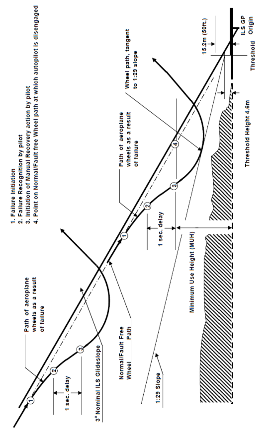
Figure FT-1: Deviation Profile Method
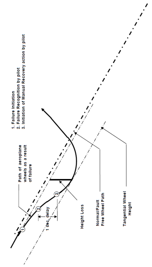
Figure FT-2: Height Loss Method
4.3 Autopilot Override
The initial tests to demonstrate compliance should be accomplished at an intermediate altitude and airspeed e.g. 4500 m (15000 ft) MSL and 460 km/h (250 kt). With the autopilot engaged in altitude hold, the pilot should apply a low force (sustained and incremental) to the control wheel (or equivalent) and verify that the automatic trim system does not produce motion resulting in a hazardous condition. The pilot should then gradually increase the applied force to the control wheel (or equivalent) until the autopilot disengages. When the autopilot disengagement occurs, observe the transient response of the aeroplane. Verify that the transient response is in compliance with Section 8.4 of AMC No. 1 to CS 25.1329.
Disengagement caused by flight crew override should be verified by applying an input on the control wheel (or equivalent) to each axis for which the FGS is designed to disengage, i.e. the pitch and roll yoke, or the rudder pedals (if applicable). The inputs by the pilot should build up to a point where they are sharp and forceful, so that the FGS can immediately be disengaged for the flight crew to assume manual control of the aeroplane.
If the autopilot is designed such that it does not automatically disengage during an autopilot override and instead provides a flight deck Alert to mitigate any potentially hazardous conditions, the timeliness and effectiveness of this Alert. The pilot should follow the evaluation procedure identified above until such time as an Alert is provided. At that time, the pilot should respond to the Alert in a responsive manner consistent with the level of the alert (i.e., a Caution, a Warning) and with the appropriate flight crew procedure defined for that Alert. When the autopilot is manually disengaged, observe the transient response of the aeroplane and verify that the transient response is in compliance with AMC No. 1 to CS 25.1329 Section 8.4.
After the initial tests have been successfully completed, the above tests should be repeated at higher altitudes and airspeeds until reaching MMO at high cruise altitudes.
[Amdt 25/4]
CS 25.1331 Instruments using a power supply
ED Decision 2003/2/RM
(a) For each instrument required by CS 25.1303(b) that uses a power supply, the following apply:
(1) Each instrument must have a visual means integral with the instrument, to indicate when power adequate to sustain proper instrument performance is not being supplied. The power must be measured at or near the point where it enters the instruments. For electric instruments, the power is considered to be adequate when the voltage is within approved limits.
(2) Each instrument must, in the event of the failure of one power source, be supplied by another power source. This may be accomplished automatically or by manual means. The failure of one power source must not affect the same instrument of both pilot stations.
(3) If an instrument presenting flight and/or navigation data receives information from sources external to that instrument and loss of that information would render the presented data unreliable, a clear and unambiguous visual warning must be given to the crew when such loss of information occurs that the presented data should not be relied upon. The indication must be incorporated in the instrument.
(b) As used in this paragraph, ‘instrument’ includes devices that are physically contained in one unit, and devices that are composed of two or more physically separate units or components connected together (such as a remote indicating gyroscopic direction indicator that includes a magnetic sensing element, a gyroscopic unit, an amplifier, and an indicator connected together).
ED Decision 2016/010/R
(See AMC 25.1333)
(a) For systems that operate the instruments required by CS 25.1303(b), which are located at each pilot’s station, means must be provided to connect the required instruments at the first pilot’s station to operating systems, which are independent of the operating systems at other flight crew stations, or other equipment.
(b) Equipment, systems, and installations must be designed so that sufficient information is available to assure control of the aeroplane in airspeed, altitude, direction and attitude by one of the pilots without additional flight crew action after any single failure or combination of failures that is not assessed to be extremely improbable (see AMC 25.1333(b)); and
(c) Additional instruments, systems, or equipment may not be connected to the operating systems for the instruments required by CS 25.1303(b), unless provisions are made to ensure the continued normal functioning of the required instruments in the event of any malfunction of the additional instruments, systems, or equipment which is not shown to be extremely improbable.
[Amdt 25/18]
AMC 25.1333(b) Instruments systems
ED Decision 2003/2/RM
1. Attitude displays systems. If three displays are used to show compliance with CS 25.1333(b), the reliability and independence of those displays should be confirmed by a suitable assessment in accordance with CS 25.1309. Each display should have independent sensors and power supplies. If a total failure of the generated electrical power causes the loss of both main instruments, the power supply to the third (standby) attitude indicator and its appropriate lighting should be such that the display is usable from each pilot’s station for a time duration in accordance with AMC 25.1351(d).
Note: the time for which the display remains usable will be stated in the Aeroplane Flight Manual (AFM).
2. Airspeed, altitude, and direction display systems. The reliability and independence of the displays used to show compliance with CS 25.1333(b) should be sufficient to ensure continued safe flight and landing appropriate to the intended operation of the aeroplane.
Historically, “sufficient information” to control attitude, airspeed, altitude, and direction has been provided by specific indicators of the state of each parameter. However, since control is considered to be the ability to change or maintain a given parameter to a desired value, it is assumed that these parameters will be available without flight crew action.
There may be alternate parameters in the cockpit that provide equivalent means to control attitude, airspeed, altitude and direction, without displaying those parameters directly (for example, without display of standby airspeed, by using a suitable angle-of-attack display). For these alternate cases, compliance to CS 25.1333(b) must be shown by analysis and flight test.
CS 25.1337 Powerplant instruments
ED Decision 2003/2/RM
(a) Instruments and instrument lines
(1) Each powerplant instrument line must meet the requirements of CS 25.993 and CS 25.1183.
(2) Each line carrying flammable fluids under pressure must –
(i) Have restricting orifices or other safety devices at the source of pressure to prevent the escape of excessive fluid if the line fails; and
(ii) Be installed and located so that the escape of fluids would not create a hazard.
(3) Each powerplant instrument that utilises flammable fluids must be installed and located so that the escape of fluid would not create a hazard.
(b) Fuel quantity indicator. There must be means to indicate to the flight-crew members, the quantity, in litres, (gallons), or equivalent units, of usable fuel in each tank during flight. In addition –
(1) Each fuel quantity indicator must be calibrated to read ‘zero’ during level flight when the quantity of fuel remaining in the tank is equal to the unusable fuel supply determined under CS 25.959;
(2) Tanks with interconnected outlets and airspaces may be treated as one tank and need not have separate indicators; and
(3) Each exposed sight gauge, used as a fuel quantity indicator, must be protected against damage.
(c) Fuel flow meter system. If a fuel flow meter system is installed, each metering component must have a means for bypassing the fuel supply if malfunction of that component severely restricts fuel flow.
(d) Oil quantity indicator. There must be a stick gauge or equivalent means to indicate the quantity of oil in each tank. If an oil transfer or reserve oil supply system is installed, there must be a means to indicate to the flight crew, in flight, the quantity of oil in each tank.
(e) Turbo-propeller blade position indicator. Required turbo-propeller blade position indicators must begin indicating before the blade moves more than 8° below the flight low pitch stop. The source of indication must directly sense the blade position.