
ED Decision 2003/2/RM
The aeroplane may not have design features or details that experience has shown to be hazardous or unreliable. The suitability of each questionable design detail and part must be established by tests.
ED Decision 2021/015/R
(See AMC 25.603; for composite materials, see AMC 20-29; for use of glass in passenger cabins, see AMC No 2 to CS 25.603(a))
The suitability and durability of materials used for parts, the failure of which could adversely affect safety, must:
(a) be established on the basis of experience or tests; (see AMC No°1 to CS 25.603(a));
(b) conform to approved specifications that ensure their having the strength and other properties assumed in the design data (see AMC 25.603(b)); and
(c) take into account the effects of environmental conditions, e.g. temperature and humidity, expected in service.
[Amdt 25/9]
[Amdt 25/18]
[Amdt 25/19]
[Amdt 25/27]
AMC 25.603 Suitability and durability of materials
ED Decision 2021/015/R
The term ‘material’ is differently interpreted, ranging from raw feedstock material to the material state in a final complex part configuration that may have undergone various processes. CS 25.603, CS 25.605, CS 25.613, and AMC 25.613 should therefore be considered together to ensure the coherent and safe design and production of parts and thus maintain occupant and aeroplane safety throughout the aeroplane’s operational life. This is of growing importance as more and more production methods allow the design of complex part configurations for which the characteristics of the materials are defined close to completion of the part production, e.g. castings, composite resin transfer methods, bonding, or additive manufacturing methods. The applicants should therefore discuss with EASA, at an early stage of the certification project, potential details supporting the means of compliance with CS 25.603, CS 25.605, and CS 25.613.
Note: organisations engaged in the design and certification of modifications or repairs should also comply with these CSs and consider the related AMC.
Appropriately defined tests and analysis pyramids (e.g. as outlined in AMC 20-29 for composite materials) should support the certification of materials, processes, and/or fabrication methods, including the development of the associated design values in more complex part configurations and assemblies.
[Amdt No: 25/27]
AMC No 1 to CS 25.603(a) Suitability and durability of materials — Experience or tests
ED Decision 2021/015/R
To show compliance with CS 25.603 and CS 25.605, applicants may use previous applicable experience and/or tests together with material specifications and material process specifications. Applicants should therefore carefully consider the controls on materials and material processing that are appropriate to the design data to be used for any part (e.g. controls on additive manufacturing powder material handling processes). However, as material strength and other properties may result from the process limitations that are specific to the configuration of some complex parts, the applicability of previous experience to new part configurations may be limited.
Shared databases: when the material strength and other properties that are used in the design data are not only influenced by the constituent materials and/or material processes, but also by the manufacturing and assembly processes, demonstrating controls on constituent materials and material processes may assist applicants in developing the final design data. For example, if an applicant successfully demonstrates data equivalence with established and accepted databases, this may create confidence in the applicant’s production processes, if not providing existing design values.
[Amdt No: 25/27]
AMC No 2 to CS 25.603(a) Suitability and durability of materials — Large glass items
ED Decision 2021/015/R
1. General
This AMC defines acceptable minimum performance standards for the specific case of large glass items used as an interior material in passenger cabin installations whereby the glass items carry no other loads than those resulting from the mass of the glass itself, rapid depressurisation, or abuse loading.
Large glass items should be shown not to be a hazard during events such as an emergency landing and cabin depressurisation.
1.1. A large glass item is defined as:
(a) a glass item with a dimension that exceeds 51 cm (20 in.);
(b) a glass panel with a surface area on one side that exceeds 0.12 m² (200 in.²); or
(c) a glass item with a mass exceeding 4 kg.
In case of multiple items in close proximity, the accumulated surface area of glass as well as the total mass should be considered (i.e. effects such as tiling should be considered).
1.2. A large glass item should meet the following requirements whenever installed in compartments that may be occupied during taxiing, take-off, and landing, or may be traversed during an emergency evacuation:
(a) The glass item should be subjected to, and pass, ball impact testing (see paragraph 2 below).
(b) The glass item should be subjected to, and pass, abuse load testing (see paragraph 3 below).
(c) The glass item should meet the requirements outlined in CS 25.561(b)(3), (c) and (d). A safety factor of 2.0 should be applied to glass items to account for variability in the production of the material and for long-term degradation.
(d) Cracking of glass should not produce a condition where the material may become hazardous to the occupants (e.g. sharp edges, splinters or separated pieces). This requires destructive testing. If any of the test conditions defined below (see paragraphs 2 and 3 below) do not result in a significant failure of the glass item, testing at a higher impact energy (ball impact test) or load (abuse load test) should be performed until destruction, or until an impact energy of 80 J or double the specified abuse load is reached.
Tests should be performed for worst-case conditions (e.g. the largest glass item should be tested with the maximum engraving). Similarity justification may then be used for other items.
These tests do not need to be performed for glass items that have traditionally been installed in large aeroplanes, provided that their installation method, location, etc. are not unusual (e.g. standard lavatory mirrors, light bulbs, light tubes, galley equipment).
The instructions for continued airworthiness should reflect the fastening method used and should ensure the reliability of all methods used (e.g. life limit of adhesives, or scheduled check for security of a clamp connection). For example, inspection methods and intervals for an adhesive-based design should be defined in accordance with adhesion data from the manufacturer of the adhesive, or actual adhesion test data, as necessary.
2. Ball Impact Tests
The test procedure(s) and pass/fail criteria of the Underwriters Laboratories standard UL 61965, Mechanical safety for cathode ray tubes, Edition 2, 27 July 2004, or former UL 1418, Standard for safety cathode ray tubes, Edition 5, 31 December 1992, or other equivalent approved method are the basis of the ball impact strength and no-hole tests described in this paragraph, combined with the impact energy in Section 5.12.2 of ANSI/SAE Z26.1, Safety glazing materials for glazing motor vehicles and motor vehicle equipment operating on land highways — safety standard, 1 December 1997.
The glass samples should be installed in a test fixture representative of the actual installation in the cabin.
2.1. Strength Test
The large glass item should be subjected to a single impact applied in accordance with the test conditions of paragraph 2.3 below. The impact energy should be 21 J, caused by a 51-mm diameter ball or, alternatively, by a 40-mm diameter ball, as specified in paragraph 2.3.2 below.
The test is passed if the expulsion of glass within a 1-min period after the initial impact satisfies the following criteria:
(a) there is no glass particle (a single piece of glass having a mass greater than 0.025 g) between the 0.90 and 1.50-m barriers (see paragraph 2.3.1) on either side (if appropriate);
(b) the total mass of all pieces of glass between the 0.90 and 1.50-m barriers (see paragraph 2.3.1) does not exceed 0.1 g on either side (if appropriate); and
(c) there is no glass expelled beyond the 1.50-m barrier (see paragraph 2.3.1) on either side (if appropriate).
2.2 No-Hole Test
The large glass item should be subjected to a single impact applied in accordance with the test conditions of paragraph 2.3 below. The impact energy should be 3.5 J, caused by a 51-mm diameter ball as specified in paragraph 2.3.2 below.
The test is passed if the large glass item does not develop any opening that may allow a 3 mm diameter rod to enter.
Note: If the large glass item does not develop any opening that would allow a 3 mm rod to enter when subjected to the strength test defined in paragraph 2.1 above, the no-hole test defined in this paragraph does not need to be performed.
2.3 Test Conditions
2.3.1 Test Apparatus and Setup
The large glass item should be mounted in a way representative of the aeroplane installation.
The centre of the large glass item should be 1.00 ± 0.05 m above the floor.
For the strength test (see paragraph 2.1 above), two barriers, each one made of material 10–20 mm thick, 250 mm high, and 2.00 m long, should be placed on the floor in front of the test item (or on both sides in case of a glass partition) at the specified location, measured horizontally from the front surface of the large glass item to the near surface of the barrier. The barriers may be less than 2.00 m long, provided that they extend to the walls of the test room. A non-skid surface such as a blanket or rug may be placed on the floor.
A solid, smooth, steel ball of the size specified in paragraph 2.3.2 below should be suspended by suitable means such as a fine wire or chain and allowed to fall freely as a pendulum and strike the large glass item with the specified impact energy. The large glass item should be placed in a way that its surface is vertical and in the same vertical plane as the suspension point of the pendulum. A single impact should be applied to any point on the surface of the large glass item at a distance of at least 25 mm from the edge of the surface.
2.3.2 Impact Objects
The 51-mm diameter steel ball, used as an impact object, should have a mass of approximately 0.5 kg and a minimum Scale C Rockwell Hardness of 60.
The 40-mm diameter steel ball, used as an impact object, should have a mass of approximately 0.23 kg and a minimum Scale C Rockwell Hardness of 60.
3. Abuse Loads Tests
The large glass item should withstand the abuse loads defined in paragraph 3.2 below when subjected to the test conditions defined in paragraph 3.1. The panel should remain attached to the fixture, and any failure should be shown to be non-hazardous (e.g. no sharp edges, no separation of pieces).
3.1 Test conditions
Abuse loads should be applied:
(a) at the points that would create the most critical loading conditions; and
(b) at least at the geometrical centre, and at one point located along the perimeter.
For the above-mentioned load applications, it is acceptable to use any loading pad with a shape and dimensions that fit into a 15.24-cm (6-in.) diameter circle.
For all tests, the glass item should be mounted in a test fixture representative of the actual installation in the cabin.
3.2 Loads to be applied
Abuse loads should be considered as ultimate loads, therefore, no additional factors (e.g. fitting factors, casting factors, etc.) need to be applied for abuse load analysis/testing.
Unless it is justified that one or more abuse load cases are not applicable due to the shape/size/location of the glass item making it unlikely or impossible for persons to apply loads in the direction(s) concerned, the following abuse loads should be considered (see also Figure 1 below):
3.2.1 Pushing loads
Pushing loads are 133 daN (300 lbf) from 0–1.5 m (60 in.) above the floor, reducing linearly to 44 daN (100 lbf) at 2 m (80 in.) above the floor level (see (1) in Figure 1 below).
3.2.2 Pulling loads
One-hand pull loads (where it is not possible to grab with two hands) are 66 daN (150 lbf) from 0–1.5 m (60 in.) above the floor, reducing linearly to 22 daN (50 lbf) at 2 m (80 in.) above the floor level (see (3) in Figure 1 below).
Two-hands pull loads are 133 daN (300 lbf) from 0–1.5 m (60 in.) above the floor, reducing linearly to 44 daN (100 lbf) at 2 m (80 in.) above the floor level (see (1) in Figure 1 below).
3.2.3 Up loads
Up loads are 66 daN (150 lbf) from 0–1.5 m (60 in.) above the floor, reducing linearly to 22 daN (50 lbf) at 2 m (80 in.) above the floor level (see (2) in Figure 1 below).
3.2.4 Downloads
Downloads are 133 daN (300 lbf) from 0-1.5 m (60 in.) above the floor, reducing linearly to 44 daN (100 lbf) at 2 m (80 in.) above the floor level (see (1) in Figure 1 below).
3.2.5 Stepping, Seating loads
In the case of large glass items which may be stepped or sat on, a load of 222 daN (500 lbf) should be used. This load is to be applied at the most critical point, and on any relevant surface up to 1 m (38 in.) above the floor level (see (4) in Figure 1 below).
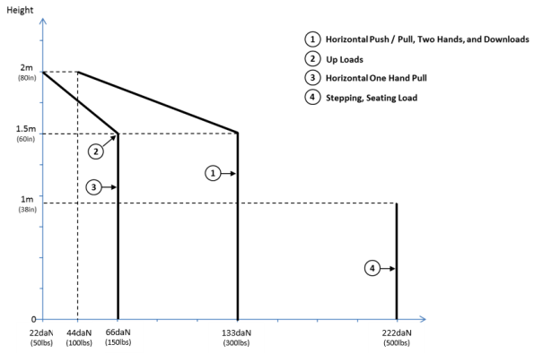
Figure 1
[Amdt No: 25/19]
[Amdt No: 25/27]
ED Decision 2021/015/R
The approved material specifications and material process specifications should:
— be suitable for the application;
— define material and material process controls;
— include requirements to assist the applicant in managing raw/feedstock/unfinished materials, as appropriate to the technology (e.g. the feedstock powder used in additive manufacturing, or matrix systems used in pre-impregnated composites).
The material strength and other properties that are used in design data (including fatigue and damage tolerance characteristics, when applicable) are governed by, and can be significantly sensitive to, the related variables of the material production process (including raw-material considerations). Furthermore, these properties may also be influenced by other higher-level fabrication processes (manufacturing and assembly), including other post-processing activities (e.g. adhesive material and bonding properties produced in a bonded joint of a complex part may not be the same as those produced in a test coupon).
The material specifications, material process specifications, and/or production drawings should identify key characteristics and parameters to be monitored by in-process quality control, including the acceptable limits to the characteristics of materials and processes (e.g. acceptable anomalies or flaws), and should address anisotropy, when applicable. This information may also help applicants identify other defect types and damage modes than the anomalies and flaws that are accepted under the specifications, including those that may occur in service. Such data may be used to help applicants show compliance with other specifications, e.g. CS 25.571. However, showing compliance with CS 25.571 does not relieve from the requirement for material process controls.
Note: approved material specifications and approved material process specifications can be, for example, industry or military specifications, or European Technical Standard Orders (ETSOs).
[Amdt No: 25/27]
ED Decision 2021/015/R
(See AMC 25.605)
(a) The fabrication methods used (i.e. the manufacturing and assembly methods, including consideration of the materials and material processes) must produce the strength and other properties necessary to ensure a consistently safe part. If a fabrication method includes processes that require close control to reach this objective, then those processes must be performed under representative approved fabrication process specifications, supported by appropriately approved material specifications (including considering the raw/feedstock/unfinished material specifications) with appropriate controls for the design data.
(b) Each new fabrication method must be substantiated by a test programme that is representative of the application.
[Amdt No: 25/27]
AMC 25.605(a) Fabrication methods — Approved process specifications
ED Decision 2021/015/R
Examples of fabrication method processes that may require close control to consistently produce safe parts include the following:
— castings,
— composite resin transfer methods,
— bonding,
— welding,
— heat-treating, or
— additive manufacturing methods.
Fabrication method process specifications should include all critical inspection steps and/or process controlled steps, and should be substantiated (they may require re-evaluation and new substantiation, if modified later). All the inherent part characteristics that result from the fabrication method and affect the material strength and other properties should be closely correlated with non‑destructive inspection (NDI) and/or process control variables. Furthermore, the applicant should show that the equipment used to support the process-critical manufacturing steps (particularly those steps that are not directly supported and controlled through inspection) is under appropriate process control, to ensure the consistent production of safe parts.
Note 1: ‘safe parts’ must comply with CS 25.603 and CS 25.605 to ensure safety by maintaining the appropriate ‘material strength and other properties’ that are assumed in the design data. Therefore, applicants are reminded that, beyond the consideration of airframe strength, these CSs are also applicable to other applications for which safety relies on strength or stiffness, e.g. system structures. Furthermore, the reference to ‘other properties’ is intended to ensure that safety is also maintained for applications for which safety relies on ‘other properties’ (for example, safe interior cabin parts that rely upon suitable flammability properties).
Note 2: approved fabrication process specifications and approved material specifications can be, for example, industry or military specifications, or European Technical Standard Orders (ETSOs).
[Amdt No: 25/27]
AMC 25.605(b) New fabrication methods — Test programme
ED Decision 2021/015/R
The test programme should initially consider the material strength and other properties resulting from each new fabrication method (‘new’ means new to the industry, an applicant, or an application configuration). The scope of the test programme should include considering the potential for anisotropic properties unless the applicant has already established an understanding of these properties.
The test programme that is required for the certification of new fabrication methods should be used to evaluate the critical process variables. Based on that evaluation, the applicant should establish in the fabrication specifications the relevant parameters that govern the final material strength and other properties of the part at the time of its production and throughout its operational life. Furthermore, the applicant should evaluate the sensitivity of the material strength and other properties to the critical process variables to ensure that the established parameters are both robust and practical.
Note: the test programme may also be used to help applicants understand the defect types and damage modes to be considered when showing compliance with other specifications, e.g. CS 25.571. Understanding the potential defects and damage modes is particularly important for sensitive fabrication processes, e.g. those used for structural bonding.
[Amdt No: 25/27]
ED Decision 2003/2/RM
(See AMC 25.607)
(a) Each removable bolt, screw, nut, pin or other removable fastener must incorporate two separate locking devices if –
(1) Its loss could preclude continued flight and landing within the design limitations of the aeroplane using normal pilot skill and strength; or
(2) Its loss could result in reduction in pitch, roll or yaw control capability or response below that required by Subpart B of this CS-25.
(b) The fasteners specified in sub-paragraph (a) of this paragraph and their locking devices may not be adversely affected by the environmental conditions associated with the particular installation.
(c) No self-locking nut may be used on any bolt subject to rotation in operation unless a non-friction locking device is used in addition to the self-locking device.
ED Decision 2003/2/RM
FAA Advisory Circular AC 20-71 Dual Locking Devices on Fasteners, date 12-8-70, is accepted by the Agency as providing acceptable means of compliance with CS 25.607.
CS 25.609 Protection of structure
ED Decision 2016/010/R
(See AMC 25.609)
Each part of the structure must-
(a) Be suitably protected against deterioration or loss of strength in service due to any cause, including –
(1) Weathering;
(2) Corrosion; and
(3) Abrasion; and
(b) Have provisions for ventilation and drainage where necessary for protection.
[Amdt 25/18]
AMC 25.609 Protection of structure
ED Decision 2003/2/RM
The comprehensive and detailed material standards accepted in the member states will be accepted as satisfying the requirement of CS 25.609.
CS 25.611 Accessibility provisions
ED Decision 2008/006/R
(a) Means must be provided to allow inspection (including inspection of principal structural elements and control systems), replacement of parts normally requiring replacement, adjustment, and lubrication as necessary for continued airworthiness. The inspection means for each item must be practicable for the inspection interval for the item. Non-destructive inspection aids may be used to inspect structural elements where it is impracticable to provide means for direct visual inspection if it is shown that the inspection is effective and the inspection procedures are specified in the maintenance manual required by CS 25.1529.
(b) Electrical wiring interconnection systems must meet the accessibility requirements of CS 25.1719.
[Amdt 25/5]
CS 25.613 Material strength properties and Material Design Values
ED Decision 2005/006/R
(See AMC 25.613)
(a) Material strength properties must be based on enough tests of material meeting approved specifications to establish design values on a statistical basis.
(b) Material design values must be chosen to minimise the probability of structural failures due to material variability. Except as provided in sub-paragraphs (e) and (f) of this paragraph, compliance must be shown by selecting material design values which assure material strength with the following probability:
(1) Where applied loads are eventually distributed through a single member within an assembly, the failure of which would result in loss of structural integrity of the component, 99% probability with 95% confidence.
(2) For redundant structure, in which the failure of individual elements would result in applied loads being safely distributed to other load carrying members, 90% probability with 95% confidence.
(c) The effects of environmental conditions, such as temperature and moisture, on material design values used in an essential component or structure must be considered where these effects are significant within the aeroplane operating envelope.
(d) Reserved
(e) Greater material design values may be used if a “premium selection” of the material is made in which a specimen of each individual item is tested before use to determine that the actual strength properties of that particular item will equal or exceed those used in design.
(f) Other material design values may be used if approved by the Agency.
[Amdt 25/1]
AMC 25.613 Material strength properties and material design values
ED Decision 2021/015/R
1. Purpose. This AMC sets forth an acceptable means, but not the only means, of demonstrating compliance with the provisions of CS-25 related to material strength properties and material design values.
2. Related Certification Specifications.
CS 25.571 “Damage-tolerance and fatigue evaluation of structure”
CS 25.603 “Materials”
CS 25.613 "Material strength properties and material design values”
3. General. CS 25.613 contains the requirements for material strength properties and material design values. Material properties used for fatigue and damage tolerance analysis are addressed by CS 25.571 and AMC 25.571(a).
When developing the material strength properties and material design values, the applicant should also consider potential anisotropies and establish all properties and design values relevant to the application of the material.
4. Material Strength Properties and Material Design Values.
4.1. Definitions.
Material strength properties. Material properties that define the strength related characteristics of any given material. Typical examples of material strength properties are: ultimate and yield values for compression, tension, bearing, shear, etc.
Material design values. Material strength properties that have been established based on the requirements of CS 25.613(b) or other means as defined in this AMC. These values are generally statistically determined based on enough data that when used for design, the probability of structural failure due to material variability will be minimised. Typical values for moduli can be used.
Aeroplane operating envelope. The operating limitations defined for the product under Subpart G of CS-25.
4.2. Statistically Based Design Values. Design values required by CS 25.613(b) must be based on sufficient testing to assure a high degree of confidence in the values. In all cases, a statistical analysis of the test data must be performed.
The ‘A’ and ‘B’ properties published in the SAE ‘Metallic Materials Properties Development and Standardization (MMPDS) Handbook’ or ESDU 00932 are acceptable, as are the statistical methods specified in the applicable chapters/sections of these handbooks. Other methods of developing material design values may be acceptable to EASA.
The test specimens used for material property certification testing should be made from material produced using production processes. Test specimen design, test methods, and testing should:
(i) conform to universally accepted standards such as those of the American Society for Testing Materials (ASTM), European Aerospace Series Standards (EN), International Standard Organisation (ISO), or other national standards acceptable to the Agency, or:
(ii) conform to those detailed in the applicable chapters/sections of the SAE MMPDS Handbook, Composite Materials Handbook 17 (CMH-17), ESDU 00932 or other accepted equivalent material data handbooks, or:
(iii) be accomplished in accordance with an approved test plan which includes definition of test specimens and test methods. This provision would be used, for example, when the material design values are to be based on tests that include effects of specific geometry and design features as well as material.
EASA may approve the use of other material test data after review of test specimen design, test methods, and test procedures that were used to generate the data.
The use of some materials and processes may allow the applicant to design parts for which the material strength and other properties are produced during production or repair. Consequently, the use of simple material test coupons (as typically produced, independent of the part) at the base of a typical test pyramid (e.g. as defined in AMC 20‑29 for ‘composite structures’) may not be representative of the material strength and other properties of the final part. When a higher test pyramid is required, then the applicant may need to reduce (for practical reasons) the number of specimens below what is normally expected for generating statistically significant values, e.g. as those associated with A and B basis data (as defined in the MMPDS Handbook). Therefore, other mitigating measures are likely necessary (e.g. coupon testing of prolongations, testing of coupons from sections of production parts, other sampling strategies, more intensive non-destructive inspection (NDIs), etc.). Until industry establishes standards for such situations, the applicant should agree with EASA whether and how to use test articles of a higher test pyramid, as well as associated small datasets, to generate material and design data. In that agreement, EASA may give credit to the applicant for applicable established practices.
4.3. Consideration of Environmental Conditions. The material strength properties of a number of materials, such as non-metallic composites and adhesives, can be significantly affected by temperature as well as moisture absorption. For these materials, the effects of temperature and moisture should be accounted for in the determination and use of material design values. This determination should include the extremes of conditions encountered within the aeroplane operating envelope. For example, the maximum temperature of a control surface may include effects of direct and reflected solar radiation, convection and radiation from a black runway surface and the maximum ambient temperature. Environmental conditions other than those mentioned may also have significant effects on material design values for some materials and should be considered.
4.4. Use of Higher Design Values Based on Premium Selection. Design values greater than those determined under CS 25.613(b) may be used if a premium selection process is employed in accordance with CS 25.613(e). In that process, individual specimens are tested to determine the actual strength properties of each part to be installed on the aircraft to assure that the strength will not be less than that used for design.
The applicant should have data available to understand if a material is anisotropic and should account for this condition during testing.
If premium selection is to be used, the test procedures and acceptance criteria must be specified on the design drawing.
4.5. Other Material Design Values. Previously used material design values, with consideration of the source, service experience and application, may be approved by the Agency on a case by case basis (e.g. "S" values of "The Metallic Materials Properties Development and Standardization (MMPDS) handbook" or ESDU 00932).
4.6. Material Specifications and Processes. Materials should be produced using production specifications and processes accepted by the Agency.]
[Amdt 25/1]
[Amdt 25/27]
ED Decision 2003/2/RM
The factor of safety prescribed in CS 25.303 must be multiplied by the highest pertinent special factor of safety prescribed in CS 25.621 through CS 25.625 for each part of the structure whose strength is –
(a) Uncertain.
(b) Likely to deteriorate in service before normal replacement; or
(c) Subject to appreciable variability because of uncertainties in manufacturing processes or inspection methods.
Where the Agency is not satisfied in a specific case that a special factor is the correct approach to ensuring the necessary integrity of the parts of the structure under service conditions, other appropriate measures must be taken.
ED Decision 2005/006/R
(see AMC 25.621.)
(a) General. For castings used in structural applications, the factors, tests, and inspections specified in sub-paragraphs (b) through (d) of this paragraph must be applied in addition to those necessary to establish foundry quality control. The inspections must meet accepted specifications. Sub-paragraphs (c) and (d) of this paragraph apply to any structural castings except castings that are pressure tested as parts of hydraulic or other fluid systems and do not support structural loads.
(b) Bearing stresses and surfaces. The casting factors specified in sub-paragraphs (c) and (d) of this paragraph:
(1) Need not exceed 1.25 with respect to bearing stresses regardless of the method of inspection used; and
(2) Need not be used with respect to the bearing surfaces of a part whose bearing factor is larger than the applicable casting factor.
(c) Critical castings. (See AMC 25.621(c)) Each casting whose failure could preclude continued safe flight and landing of the aeroplane or could result in serious injury to occupants is considered a critical casting. Each critical casting must have a factor associated with it for showing compliance with strength and deformation requirements, and must comply with the following criteria associated with that factor:
(1) A casting factor of 1.0 or greater may be used, provided that:
(i) It is demonstrated, in the form of process qualification, proof of product, and process monitoring that, for each casting design and part number, the castings produced by each foundry and process combination have coefficients of variation of the material properties that are equivalent to those of wrought alloy products of similar composition. Process monitoring must include testing of coupons cut from the prolongations of each casting (or each set of castings, if produced from a single pour into a single mould in a runner system) and, on a sampling basis, coupons cut from critical areas of production castings. The acceptance criteria for the process monitoring inspections and tests must be established and included in the process specifications to ensure the properties of the production castings are controlled to within levels used in design.
(ii) Each casting receives:
(A) Inspection of 100 percent of its surface, using visual and liquid penetrant, or equivalent, inspection methods; and
(B) Inspection of structurally significant internal areas and areas where defects are likely to occur, using radiographic, or equivalent, inspection methods.
(iii) One casting undergoes a static test and is shown to meet the strength and deformation requirements of CS 25.305(a) and (b).
(see AMC 25.621(c)(1).)
(2) A casting factor of 1.25 or greater may be used, provided that:
(i) Each casting receives:
(A) Inspection of 100 percent of its surface, using visual and liquid penetrant, or equivalent inspection methods; and
(B) Inspection of structurally significant internal areas and areas where defects are likely to occur, using radiographic, or equivalent, inspection methods.
(ii) Three castings undergo static tests and are shown to meet:
(A) The strength requirements of CS 25.305(b) at an ultimate load corresponding to a casting factor of 1.25; and
(B) The deformation requirements of CS 25.305(a) at a load of 1.15 times the limit load.
(3) A casting factor of 1.50 or greater may be used, provided that:
(i) Each casting receives:
(A) Inspection of 100 percent of its surface, using visual and liquid penetrant, or equivalent, inspection methods; and
(B) Inspection of structurally significant internal areas and areas where defects are likely to occur, using radiographic, or equivalent, inspection methods.
(ii) One casting undergoes a static test and is shown to meet:
(A) The strength requirements of CS 25.305(b) at an ultimate load corresponding to a casting factor of 1.50; and
(B) The deformation requirements of CS 25.305(a) at a load of 1.15 times the limit load.
(d) Non-critical castings. For each casting other than critical castings, as specified in sub-paragraph (c) of this paragraph, the following apply:
(1) A casting factor of 1.0 or greater may be used, provided that compliance is shown with sub-paragraph (c)(1) of this paragraph, or with the following three conditions:
(i) Castings are manufactured to accepted specifications that specify the minimum mechanical properties of the material in the casting and provides for demonstration of these properties by testing of coupons cut from the castings on a sampling basis.
(ii) Each casting receives:
(A) Inspection of 100 percent of its surface, using visual and liquid penetrant, or equivalent, inspection methods; and
(B) Inspection of structurally significant internal areas and areas where defects are likely to occur, using radiographic, or equivalent, inspection methods.
(iii) Three sample castings undergo static tests and are shown to meet the strength and deformation requirements of CS 25.305(a) and (b).
(2) A casting factor of 1.25 or greater may be used, provided that each casting receives:
(i) Inspection of 100 percent of its surface, using visual and liquid penetrant, or equivalent, inspection methods; and
(ii) Inspection of structurally significant internal areas and areas where defects are likely to occur, using radiographic, or equivalent, inspection methods.
(3) A casting factor of 1.5 or greater may be used, provided that each casting receives inspection of 100 percent of its surface using visual and liquid penetrant, or equivalent, inspection methods.
(4) A casting factor of 2.0 or greater may be used, provided that each casting receives inspection of 100 percent of its surface using visual inspection methods.
(5) The number of castings per production batch to be inspected by non-visual methods in accordance with sub-paragraphs (d)(2) and (d)(3) of this paragraph may be reduced from 100% when an accepted quality control procedure is established.
[Amdt 25/1]
ED Decision 2005/006/R
1. Purpose.
CS 25.621 is an additional rule/requirement for structural substantiation of cast parts and components. It is used in combination with a number of other paragraphs, and does not replace or negate compliance with any other paragraph of CS-25. The intent of this AMC is to provide general guidance on the use and background of "Casting Factors" as required by CS 25.621.
2. General Guidance For Use Of Casting Factors.
2.1 For the analysis or testing required by CS 25.307, the ultimate load level must include limit load multiplied by the required factor required by CS 25.619. The testing required in accordance with CS 25.621 may be used in showing compliance with CS 25.305 and CS 25.307. These factors need not be considered in the fatigue and damage tolerance evaluations required by CS 25.571.
2.2 The inspection methods prescribed by CS 25.621(c) and (d) for all production castings must be such that 100% of the castings are inspected by visual and liquid penetrant techniques, with total coverage of the surface of the casting. With regard to the required radiographic inspection, each production casting must be inspected by this technique or equivalent inspection methods; the inspection may be limited to the structurally significant internal areas and areas where defects are likely to occur.
2.3 With the establishment of consistent production, it is possible to reduce the inspection frequency of the non-visual inspections required by the rule for non-critical castings, with the acceptance of the Agency. This is usually accomplished by an accepted quality control procedure incorporating a sampling plan. (Refer to CS 25.621(d)(5).)
2.4 The static test specimen(s) should be selected on the basis of the foundry quality control inspections, in conjunction with those inspections prescribed in CS 25.621(c) and (d). An attempt should be made to select the worst casting(s) from the first batch produced to the production standard.
2.5 If applicable, the effects on material properties due to weld rework should be addressed. The extent and scope of weld rework should be detailed in the manufacturing specifications as well as on the design drawings.
3. Background.
3.1 Regulatory Background. CS 25.621 (“Casting factors”) requires classification of structural castings as either “critical” or “non-critical.” Depending on classification, the requirement specifies the accomplishment of certain inspections and tests, and the application of special factors of safety for ultimate strength and deformation.
3.2 Application of Special Factors of Safety. The application of factors of safety applied to castings is based on the fact that the casting process can be inconsistent. Casting is a method of forming an object by pouring molten metal into a mould, allowing the material to solidify inside the mould, and removing it when solidification is complete. Castings are subject to variability in mechanical properties due to this casting process, which can result in imperfections, such as voids, within the cast part. Using certain inspection techniques, for example radiographic (X-ray), it is possible to detect such imperfections above a minimum detectable size, but accurate detection depends on the dimensions of the part, the inspection equipment used, and the skill of the inspector.
3.2.1 CS 25.619 (“Special factors”) includes a requirement to apply a special factor to the factor of safety prescribed in CS 25.303 for each part of the aeroplane structure whose strength is subject to appreciable variability because of uncertainties in the manufacturing processes or inspection methods. Since the mechanical properties of a casting depend on the casting design, the design values established under CS 25.613 (“Material strength properties and material design values”) for one casting might not be applicable to another casting made to the same specification. Thus, casting factors have been necessary for castings produced by normal techniques and methodologies to ensure the structural integrity of castings in light of these uncertainties.
3.2.2 Another approach is to reduce the uncertainties in the casting manufacturing process by use of a “premium casting process” (discussed in AMC 25.621(c)(1)), which provides a means of using a casting factor of 1.0. CS 25.621 (“Casting factors”) does permit the use of a casting factor of 1.0 for critical castings, provided that:
— the manufacturer has established tight controls for the casting process, inspection, and testing; and
— the material strength properties of the casting have no more variability than equivalent wrought alloys.
[Amdt 25/1]
AMC 25.621(c) Critical Castings
ED Decision 2005/006/R
Examples of castings that may be critical are: structural attachment fittings; parts of flight control systems; control surface hinges and balance weight attachments; seat, berth, safety belt and fuel and oil tank supports and attachments; pressurised doors; and cabin pressure valves.
[Amdt 25/1]
AMC 25.621(c)(1) Premium Castings
ED Decision 2005/006/R
1. Purpose.
This AMC details an acceptable means, but not the only means, for compliance with CS 25.621 for using a casting factor of 1.0 or greater for “critical” castings used in structural applications. A premium casting process is capable of producing castings with predictable properties, thus allowing a casting factor of 1.0 to be used for these components. Three major steps, required by CS 25.621(c)(1)(i), are essential in characterising a premium casting process:
— qualification of the process,
— proof of the product, and
— monitoring of the process.
2. Definitions. For the purposes of this AMC, the following definitions apply:
2.1 Premium Casting Process: a casting process that produces castings characterised by a high quality and reliability
2.2 Prolongation: an integrally cast test bar or test coupon.
2.3 Test Casting: a casting produced specifically for the purpose of qualifying the casting process.
3. General. The objective of a premium casting process is to consistently produce castings with high quality and reliability. To this end, the casting process is one that is capable of consistently producing castings that include the following characteristics:
— Good dimensional tolerance
— Minimal distortion
— Good surface finish
— No cracks
— No cold shuts
— No laps
— Minimal shrinkage cavities
— No harmful entrapped oxide films
— Minimal porosity
— A high level of metallurgical cleanness
— Good microstructural characteristics
— Minimal residual internal stress
— Consistent mechanical properties
The majority of these characteristics can be detected, evaluated, and quantified by standard non-destructive testing methods, or from destructive methods on prolongation or casting cut-up tests. However, a number of them cannot. Thus, to ensure an acceptable quality of product, the significant and critical process variables must be identified and adequately controlled.
4. A Means of Qualification of Casting Process.
4.1 To prove a premium casting process, it should be submitted to a qualification program that is specific to a foundry/material combination. The qualification program should establish the following:
(a) The capability of the casting process of producing a consistent quality of product for the specific material grade selected for the intended production component.
(b) The mechanical properties for the material produced by the process have population coefficients of variation equivalent to that of wrought products of similar composition (i.e., plate, extrusions, and bar). Usage of the population coefficient of variation from forged products does not apply. In most cases, the coefficients of variation for tensile ultimate strength and tensile yield strength less than or equal to 3.5% and 4.0% respectively is adequate to demonstrate this equivalency of mechanical properties.
(c) The casting process is capable of producing a casting with uniform properties throughout the casting or, if not uniform, with a distribution of material properties that can be predicted to an acceptable level of accuracy.
(d) The (initial) material design data for the specified material are established.
(e) The material and process specifications are clearly defined.
4.2 For each material specification, a series of test castings from a number of melts, using the appropriate production procedures of the foundry, should be manufactured. The test casting produced should undergo a standardised inspection or investigation of non-destructive inspection and cut-up testing, to determine the consistency of the casting process.
4.3 The test casting should be representative of the intended cast product(s) with regard to section thicknesses and complexity, and should expose any limitations of the casting process. In addition, the test casting should be large enough to provide mechanical test specimens from various areas, for tensile and, if applicable, compression, shear, bearing, fatigue, fracture toughness, and crack propagation tests. If the production component complies with these requirements, it may be used to qualify the process. The number of melts sampled should be statistically significant. Typically, at least 10 melts are sampled, with no more than 10 castings produced from each melt. If the material specification requires the components to be heat-treated, this should be done in no fewer than 10 heat treatment batches consisting of castings from more than one melt. Reduction of qualification tests may be considered if the casting process and the casting alloy is already well known for aerospace applications and the relevant data are available.
4.4 Each test casting should receive a non-destructive inspection program which should include as a minimum:
— inspection of 100% of its surface, using visual and liquid penetrant, or equivalent, inspection methods; and
— inspection of structurally significant internal areas and areas where defects are likely to occur, using radiographic methods or equivalent inspection methods. The specific radiographic standard to be employed is to be determined, and the margin by which the test castings exceed the minimum required standard should be recorded.
4.4.1 The program of inspection is intended to:
(a) confirm that the casting process is capable of producing a consistent quality of product, and
(b) verify compliance with the stated objectives of a premium casting process with regard to surface finish, cracks, cold shuts, laps, shrinkage cavities, and porosity, (see paragraph 3), and
(c) ensure that the areas from which the mechanical property test samples were taken were typical of the casting as a whole with respect to porosity and cleanness.
4.4.2 Guidance on non-destructive inspection techniques and methods can be obtained from national and international standards. The standard listing below is not a comprehensive list but is given as an initial reference guide.
ASTM A802 Standard practice for steel castings, surface acceptance standards, visual examination.
ASTM A903 Standard specification for steel castings, surface acceptance standards, magnetic particle and liquid penetrant inspection.
ASTM E155 Standard Reference Radiographs for Inspection of Aluminum and Magnesium Castings.
ASTM E192 Standard Reference Radiographs for Investment Steel Castings of Aerospace Applications.
ASTM E433 Standard reference photographs for liquid penetrant inspection.
ASTM E1030 Standard test method for radiographic examination of metallic castings.
ASTM E1320 Standard Reference Radiographs for Titanium Castings.
ISO 4986 Steel castings - Magnetic particle inspection
ISO 4987 Steel castings - Penetrant inspection
ISO 4993 Steel castings - Radiographic inspection
ISO 9915 Aluminium alloy castings - Radiography testing
ISO 9916 Aluminium alloy and magnesium alloy castings - Liquid penetrant inspection
ISO 10049 Aluminium alloy castings - Visual method for assessing the porosity
ISO 11971 Visual examination of surface quality of steel castings
The test castings must show that the Foundry/Process combination is capable of producing product free of cracks, laps, and cold shuts. Ideally the test castings should be free of detectable shrinkage cavities and porosity. With regard to dimensional tolerance, distortion, and surface finish guidance for acceptance criteria can be gained from the standards cited above. Consideration that these standards are for general quality castings must be given when they are used.
4.5 All test castings should be cut up to a standardised methodology to produce the mechanical test specimens as detailed by paragraph 4.3 above. Principally, the tests are to establish the variability within the cast component, as well as to determine the variability between components from the same melt and from melt to melt. The data gathered also may be used during latter phases to identify deviations from the limits established in the process qualification and product proving programs.
4.6 All the fracture surfaces generated during the qualification program should be inspected at least visually for detrimental defects. Evidence of inclusions, oxide films, porosity or shrinkage cavities would indicate inadequate control of the casting process.
4.7 As part of the cut-up investigation, it is usually necessary to take metallographic samples for cleanness determination and microstructural characterisation.
4.8 When the process has been qualified, it should not be altered without completing comparability studies and necessary testing of differences.
5. Proof of Product
5.1 Subsequent to the qualification of the process, the production castings should be subjected to a production-proving program. Such castings should have at least one prolongation; however, large and/or complex castings may require more than one. If a number of castings are produced from a single mould with a single runner system, they may be treated as one single casting. The production-proving program should establish the following:
(a) The design values developed during the process qualification program are valid (e.g., same statistical distribution) for the production casting.
(b) The production castings have the same or less than the level of internal defects as the test castings produced during qualification.
(c) The cast components have a predictable distribution of tensile properties.
(d) The prolongation(s) is representative of the critical area(s) of the casting.
(e) The prolongation(s) consistently reflects the quality process, and material properties of the casting.
5.2 A number of (i.e., at least two) pre-production castings of each part number to be produced should be selected for testing and inspection. All of the selected castings should be non-destructively inspected in accordance with the qualification program.
(a) One of these castings should be used as a dimensional tolerance test article. The other selected casting(s) should be cut up for mechanical property testing and metallographic inspection.
(b) The casting(s) should be cut up to a standardised program to yield a number of tensile test specimens and metallographic samples. There should be sufficient cut-up tensile specimens to cover all critical (“critical” with respect to both the casting process and service loading) areas of the casting.
(c) All prolongations should be machined to give tensile specimens, and subsequently tested.
(d) The production castings should be produced to production procedures identical to those used for these pre-production castings.
5.3 On initial production, a number of castings should undergo a cut-up for mechanical property testing and metallographic inspection, similar to that performed for the pre-production casting(s). The cut-up procedure used should be standardised, although it may differ from that used for the pre-production casting(s). Tensile specimens should be obtained from the most critical areas.
(a) For the first 30 castings produced, at least 1 casting in 10 should undergo this testing program.
(b) The results from the mechanical property tests should be compared with the results obtained from the prolongations to further substantiate the correlation between prolongation(s) and the critical area(s) of the casting.
(c) In addition, if the distribution of mechanical properties derived from these tests is acceptable, when compared to the property values determined in the qualification program, the frequency of testing may be reduced. However, if the comparison is found not to be acceptable, the test program may require extension.
5.4 At no point in the production should the castings contain shrinkage cavities, cracks, cold shuts, laps, porosity, or entrapped oxide film, or have a poor surface finish, exceeding the acceptance level defined in the technical specifications.
6. Monitoring the Process.
6.1 For the product quality techniques should be employed to establish the significant/critical foundry process variables that have an impact on the quality of the product. For the product it should be shown that these variables are controlled with positive corrective action throughout production.
6.2 During production, every casting should be non-destructively inspected using the techniques and the acceptance standards employed during the qualification program.
(a) Rejections should be investigated and process corrections made as necessary.
(b) Alternative techniques may be employed if the equivalence in the acceptance levels can be demonstrated.
(c) In addition, tensile tests should be taken from the prolongations on every component produced, and the results should comply with limits developed in the process qualification and product proving programs.
(d) Additionally, as previously mentioned, a periodic casting cut-up inspection should be undertaken, with the inspection schedule as agreed upon during the proof of product program.
(e) Deviations from the limits established in the process qualification and product proving programs should be investigated and corrective action taken.
7. Modifications to the Casting Design, Material, and Process.
7.1 Additional testing may be required when alterations are made to the casting geometry, material, significant/critical process variables, process, or production foundry to verify that the alterations have not significantly changed the castings’ properties. The verification testing recommended is detailed in Table 1, below:
|
Modifications |
Verification Testing |
||||||
|
Case |
Geometry |
Material |
Process |
Foundry |
Qualification of Process |
Proof of Product |
Tests per CS 25.621(c)(1) |
|
1 |
yes |
none |
none |
none |
not necessary |
yes |
yes (b) |
|
2 |
none |
yes |
none |
none |
yes (a) |
yes |
yes (b) |
|
3 |
yes |
yes |
none |
none |
yes |
yes |
yes |
|
4 |
none |
none |
yes |
None |
yes (a) |
yes |
yes (b) |
|
5 |
none |
none |
none |
yes |
yes (a) |
yes |
yes (b) |
|
(a) The program described in paragraph 4. of this AMC to qualify a new material, process, and foundry combination may not be necessary if the following 3 conditions exist for the new combination: (1) Sufficient data from relevant castings to show that the process is capable of producing a consistent quality of product, and that the quality is comparable to or better than the old combination. (2) Sufficient data from relevant castings to establish that the mechanical properties of the castings produced from the new combination have a similar or better statistical distribution than the old combination. (3) Clearly defined material and process specifications. (b) The casting may be re-qualified by testing partial static test samples (with larger castings, re-qualification could be undertaken by a static test of the casting's critical region only). |
|||||||
[Amdt 25/1]
ED Decision 2003/2/RM
(a) Except as provided in sub-paragraph (b) of this paragraph, each part that has clearance (free fit), and that is subject to pounding or vibration, must have a bearing factor large enough to provide for the effects of normal relative motion.
(b) No bearing factor need be used for a part for which any larger special factor is prescribed.
ED Decision 2003/2/RM
For each fitting (a part or terminal used to join one structural member to another), the following apply:
(a) For each fitting whose strength is not proven by limit and ultimate load tests in which actual stress conditions are simulated in the fitting and surrounding structures, a fitting factor of at least 1·15 must be applied to each part of –
(1) The fitting;
(2) The means of attachment; and
(3) The bearing on the joined members.
(b) No fitting factor need be used –
(1) For joints made under approved practices and based on comprehensive test data (such as continuous joints in metal plating, welded joints, and scarf joints in wood); or
(2) With respect to any bearing surface for which a larger special factor is used.
(c) For each integral fitting, the part must be treated as a fitting up to the point at which the section properties become typical of the member.
(d) For each seat, berth, safety belt, and harness, the fitting factor specified in CS 25.785(f)(3) applies.
CS 25.629 Aeroelastic stability requirements
ED Decision 2020/001/R
(See AMC 25.629)
(a) General. The aeroelastic stability evaluations required under this paragraph include flutter, divergence, control reversal and any undue loss of stability and control as a result of structural deformation. The aeroelastic evaluation must include whirl modes associated with any propeller or rotating device that contributes significant dynamic forces. Compliance with this paragraph must be shown by analyses, tests, or some combination thereof as found necessary by the Agency.
(b) Aeroelastic stability envelopes. The aeroplane must be designed to be free from aeroelastic instability for all configurations and design conditions within the aeroelastic stability envelopes as follows:
(1) For normal conditions without failures, malfunctions, or adverse conditions, all combinations of altitudes and speeds encompassed by the VD/MD versus altitude envelope enlarged at all points by an increase of 15 percent in equivalent airspeed at constant Mach number and constant altitude. In addition, a proper margin of stability must exist at all speeds up to VD/MD and, there must be no large and rapid reduction in stability as VD/MD is approached. The enlarged envelope may be limited to Mach 1.0 when MD is less than 1.0 at all design altitudes; and
(2) For the conditions described in CS 25.629(d) below, for all approved altitudes, any airspeed up to the greater airspeed defined by:
(i) The VD/MD envelope determined by CS 25.335(b); or,
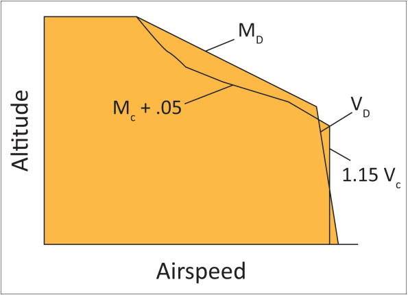
(ii) An altitude-airspeed envelope defined by a 15 percent increase in equivalent airspeed above VC at constant altitude, from sea level to the altitude of the intersection of 1.15 VC with the extension of the constant cruise Mach number line, MC, then a linear variation in equivalent airspeed to MC +.05 at the altitude of the lowest VC/MC intersection; then, at higher altitudes, up to the maximum flight altitude, the boundary defined by a .05 Mach increase in MC at constant altitude; and
(iii) Failure conditions of certain systems must be treated in accordance with CS 25.302.
(3) For failure conditions in those systems covered by CS 25.302, the margins defined in Appendix K of CS-25 apply.
(c) Balance weights. If balance weights are used, their effectiveness and strength, including supporting structure, must be substantiated.
(d) Failures, malfunctions, and adverse conditions. The failures, malfunctions, and adverse conditions which must be considered in showing compliance with this paragraph are:
(1) Any critical fuel loading conditions, not shown to be extremely improbable, which may result from mismanagement of fuel.
(2) Any single failure in any flutter damper or flutter control system.
(3) For aeroplanes not approved for operation in icing conditions, the maximum likely ice accumulation expected as a result of an inadvertent encounter.
(4) Failure of any single element of the structure supporting any engine, independently mounted propeller shaft, large auxiliary power unit, or large externally mounted aerodynamic body (such as an external fuel tank).
(5) For aeroplanes with engines that have propellers or large rotating devices capable of significant dynamic forces, any single failure of the engine structure that would reduce the rigidity of the rotational axis.
(6) The absence of aerodynamic or gyroscopic forces resulting from the most adverse combination of feathered propellers or other rotating devices capable of significant dynamic forces. In addition, the effect of a single feathered propeller or rotating device must be coupled with the failures of sub-paragraphs (d)(4) and (d)(5) of this paragraph.
(7) Any single propeller or rotating device capable of significant dynamic forces rotating at the highest likely overspeed.
(8) Any damage or failure condition, required or selected for investigation by CS 25.571. The single structural failures described in sub-paragraphs (d)(4) and(d)(5) of this paragraph need not be considered in showing compliance with this paragraph if;
(i) The structural element could not fail due to discrete source damage resulting from the conditions described in CS 25.571(e) and CS 25.903(d); and
(ii) A damage tolerance investigation in accordance with CS 25.571(b) shows that the maximum extent of damage assumed for the purpose of residual strength evaluation does not involve complete failure of the structural element.
(9) The following flight control system failure combinations where aeroelastic stability relies on flight control system stiffness and/or damping:
(i) any dual hydraulic system failure;
(ii) any dual electrical system failure; and
(iii) any single failure in combination with any probable hydraulic system or electrical system failure.
(10) Any damage, failure or malfunction, considered under CS 25.631, CS 25.671, CS 25.672, and CS 25.1309.
(11) Any other combination of failures, malfunctions, or adverse conditions not shown to be extremely improbable.
(e) Flight flutter testing. Full scale flight flutter tests at speeds up to VDF/MDF must be conducted for new type designs and for modifications to a type design unless the modifications have been shown to have an insignificant effect on the aeroelastic stability. These tests must demonstrate that the aeroplane has a proper margin of damping at all speeds up to VDF/MDF, and that there is no large and rapid reduction in damping as VDF/MDF is approached. If a failure, malfunction, or adverse condition is simulated during flight test in showing compliance with sub-paragraph (d) of' this paragraph, the maximum speed investigated need not exceed VFC/MFC if it is shown, by correlation of the flight test data with other test data or analyses, that the aeroplane is free from any aeroelastic instability at all speeds within the altitude-airspeed envelope described in sub-paragraph (b)(2) of this paragraph.
[Amdt No: 25/1]
[Amdt No: 25/18]
[Amdt No: 25/24]
AMC 25.629 Aeroelastic stability requirements
ED Decision 2020/001/R
1. General.
The general requirement for demonstrating freedom from aeroelastic instability is contained in CS 25.629, which also sets forth specific requirements for the investigation of these aeroelastic phenomena for various aeroplane configurations and flight conditions. Additionally, there are other conditions defined by the CS-25 paragraphs listed below to be investigated for aeroelastic stability to assure safe flight. Many of the conditions contained in this AMC pertain only to the current amendment of CS-25. Type design changes to aeroplanes certified to an earlier CS-25 amendment must meet the certification basis established for the modified aeroplane.
Related CS-25 paragraphs:
CS 25.251 - Vibration and buffeting
CS 25.305 - Strength and deformation
CS 25.335 - Design airspeeds
CS 25.343 - Design fuel and oil loads
CS 25.571 - Damage-tolerance and fatigue evaluation of structure
CS 25.629 - Aeroelastic stability requirements
CS 25.631 - Bird strike damage
CS 25.671 - General (Control systems)
CS 25.672 - Stability augmentation and automatic and power operated systems
CS 25.1309 - Equipment, systems and installations
CS 25.1329 - Flight Guidance system
CS 25.1419 - Ice protection
CS 25.1420 – Supercooled large drop icing conditions
2. Aeroelastic Stability Envelope
2.1. For nominal conditions without failures, malfunctions, or adverse conditions, freedom from aeroelastic instability is required to be shown for all combinations of airspeed and altitude encompassed by the design dive speed (VD) and design dive Mach number (MD) versus altitude envelope enlarged at all points by an increase of 15 percent in equivalent airspeed at both constant Mach number and constant altitude. Figure 1A represents a typical design envelope expanded to the required aeroelastic stability envelope. Note that some required Mach number and airspeed combinations correspond to altitudes below standard sea level.
2.2. The aeroelastic stability envelope may be limited to a maximum Mach number of 1.0 when MD is less than 1.0 and there is no large and rapid reduction in damping as MD is approached.
2.3. Some configurations and conditions that are required to be investigated by CS 25.629 and other CS-25 regulations consist of failures, malfunctions or adverse conditions. Aeroelastic stability investigations of these conditions need to be carried out only within the design airspeed versus altitude envelope defined by:
(i) the VD/MD envelope determined by CS 25.335(b); or,
(ii) an altitude-airspeed envelope defined by a 15 percent increase in equivalent airspeed above VC at constant altitude, from sea level up to the altitude of the intersection of 1.15 VC with the extension of the constant cruise Mach number line, MC, then a linear variation in equivalent airspeed to MC + 0.05 at the altitude of the lowest VC/MC intersection; then at higher altitudes, up to the maximum flight altitude, the boundary defined by a 0.05 Mach increase in MC at constant altitude.
Figure 1B shows the minimum aeroelastic stability envelope for fail-safe conditions, which is a composite of the highest speed at each altitude from either the VD envelope or the constructed altitude-airspeed envelope based on the defined VC and MC.
Fail-safe design speeds, other than the ones defined above, may be used for certain system failure conditions when specifically authorised by other rules or special conditions prescribed in the certification basis of the aeroplane.
FIGURE 1A. MINIMUM REQUIRED AEROELASTIC STABILITY MARGIN
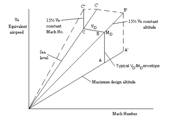
FIGURE 1B MINIMUM FAIL-SAFE CLEARANCE ENVELOPE
3. Configurations and Conditions. The following paragraphs provide a summary of the configurations and conditions to be investigated in demonstrating compliance with CS-25. Specific design configurations may warrant additional considerations not discussed in this AMC.
3.1. Nominal Configurations and Conditions. Nominal configurations and conditions of the aeroplane are those that are likely to exist in normal operation. Freedom from aeroelastic instability should be shown throughout the expanded clearance envelope described in paragraph 2.1 above for:
3.1.1. The range of fuel and payload combinations, including zero fuel in the wing, for which certification is requested.
3.1.2. Configurations with ice mass accumulations on unprotected surfaces for aeroplanes approved for operation in icing conditions. See paragraph 5.1.4.5 below.
3.1.3. All normal combinations of autopilot, yaw damper, or other automatic flight control systems.
3.1.4. All possible engine settings and combinations of settings from idle power to maximum available thrust including the conditions of one engine stopped and windmilling, in order to address the influence of gyroscopic loads and thrust on aeroelastic stability.
3.2. Failures, Malfunctions, and Adverse Conditions. The following conditions should be investigated for aeroelastic instability within the fail-safe envelope defined in paragraph 2.3. above.
3.2.1. Any critical fuel loading conditions, not shown to be extremely improbable, which may result from mismanagement of fuel.
3.2.2. Any single failure in any flutter control system.
3.2.3. For aeroplanes not approved for operation in icing conditions, ice accumulation expected as a result of an inadvertent encounter. For aeroplanes approved for operation in icing conditions, ice accumulation expected as the result of any single failure in the de-icing system, or any combination of failures not shown to be extremely improbable. See paragraph 5.1.4.5 below.
3.2.4. Failure of any single element of the structure supporting any engine, independently mounted propeller shaft, large auxiliary power unit, or large externally mounted aerodynamic body (such as an external fuel tank).
3.2.5. For aeroplanes with engines that have propellers or large rotating devices capable of significant dynamic forces, any single failure of the engine structure that would reduce the rigidity of the rotational axis.
3.2.6. The absence of aerodynamic or gyroscopic forces resulting from the most adverse combination of feathered propellers or other rotating devices capable of significant dynamic forces. In addition, the effect of a single feathered propeller or rotating device should be coupled with the failures of paragraphs 3.2.4 and 3.2.5 above.
3.2.7. Any single propeller or rotating device capable of significant dynamic forces rotating at the highest likely overspeed.
3.2.8. Any damage or failure condition, required or selected for investigation by CS 25.571. The single structural failures described in paragraphs 3.2.4 and 3.2.5 above need not be considered in showing compliance with this paragraph if;
(A) The structural element could not fail due to discrete source damage resulting from the conditions described in CS 25.571(e) and CS 25.903(d); and
(B) A damage tolerance investigation in accordance with CS 25.571(b) shows that the maximum extent of damage assumed for the purpose of residual strength evaluation does not involve complete failure of the structural element.
3.2.9. The following flight control system failure combinations where aeroelastic stability relies on flight control system stiffness and/or damping:
(i) any dual hydraulic system failure;
(ii) any dual electrical system failure; and
(iii) any single failure in combination with any probable hydraulic system or electrical system failure.
3.2.10. Any damage, failure or malfunction, considered under CS 25.631, CS 25.671, CS 25.672, and CS 25.1309. This includes the condition of two or more engines stopped or wind milling for the design range of fuel and payload combinations, including zero fuel.
3.2.11. Any other combination of failures, malfunctions, or adverse conditions not shown to be extremely improbable.
4. Detail Design Requirements.
4.1. Main surfaces, such as wings and stabilisers, should be designed to meet the aeroelastic stability criteria for nominal conditions and should be investigated for meeting fail-safe criteria by considering stiffness changes due to discrete damage or by reasonable parametric variations of design values.
4.2. Control surfaces, including tabs, should be investigated for nominal conditions and for failure modes that include single structural failures (such as actuator disconnects, hinge failures, or, in the case of aerodynamic balance panels, failed seals), single and dual hydraulic system failures and any other combination of failures not shown to be extremely improbable. Where other structural components contribute to the aeroelastic stability of the system, failures of those components should be considered for possible adverse effects.
4.3. Where aeroelastic stability relies on flight control system stiffness and/or damping, additional conditions should be considered. The actuation system should continuously provide, at least, the minimum stiffness or damping required for showing aeroelastic stability without regard to probability of occurrence for:
(i) more than one engine stopped or wind milling,
(ii) any discrete single failure resulting in a change of the structural modes of vibration (for example; a disconnection or failure of a mechanical element, or a structural failure of a hydraulic element, such as a hydraulic line, an actuator, a spool housing or a valve);
(iii) any damage or failure conditions considered under CS 25.571, CS 25.631 and CS 25.671.
The actuation system minimum requirements should also be continuously met after any combination of failures not shown to be extremely improbable (occurrence less than10-9 per flight hour). However, some combinations of failures, such as dual electrical system or dual hydraulic system failures, or any single failure in combination with any probable electrical or hydraulic system failure, are normally not demonstrated as being extremely improbable The reliability assessment should be part of the substantiation documentation. In practice, meeting the above conditions may involve design concepts such as the use of check valves and accumulators, computerised pre-flight system checks and shortened inspection intervals to protect against undetected failures.
4.4 Consideration of free play may be incorporated as a variation in stiffness to assure adequate limits are established for wear of components such as control surface actuators, hinge bearings, and engine mounts in order to maintain aeroelastic stability margins.
4.5. If balance weights are used on control surfaces, their effectiveness and strength, including that of their support structure, should be substantiated.
4.6 The automatic flight control system should not interact with the airframe to produce an aeroelastic instability. When analyses indicate possible adverse coupling, tests should be performed to determine the dynamic characteristics of actuation systems such as servo-boost, fully powered servo-control systems, closed-loop aeroplane flight control systems, stability augmentation systems, and other related powered-control systems.
5. Compliance. Demonstration of compliance with aeroelastic stability requirements for an aircraft configuration may be shown by analyses, tests, or some combination thereof. In most instances, analyses are required to determine aeroelastic stability margins for normal operations, as well as for possible failure conditions. Wind tunnel flutter model tests, where applicable, may be used to supplement flutter analyses. Ground testing may be used to collect stiffness or modal data for the aircraft or components. Flight testing may be used to demonstrate compliance of the aircraft design throughout the design speed envelope.
5.1. Analytical Investigations. Analyses should normally be used to investigate the aeroelastic stability of the aircraft throughout its design flight envelope and as expanded by the required speed margins. Analyses are used to evaluate aeroelastic stability sensitive parameters such as aerodynamic coefficients, stiffness and mass distributions, control surface balance requirements, fuel management schedules, engine/store locations, and control system characteristics. The sensitivity of most critical parameters may be determined analytically by varying the parameters from nominal. These investigations are an effective way to account for the operating conditions and possible failure modes which may have an effect on aeroelastic stability margins, and to account for uncertainties in the values of parameters and expected variations due to in-service wear or failure conditions.
5.1.1. Analytical Modelling. The following paragraphs discuss acceptable, but not the only, methods and forms of modelling aircraft configurations and/or components for purposes of aeroelastic stability analysis. The types of investigations generally encountered in the course of aircraft aeroelastic stability substantiation are also discussed. The basic elements to be modelled in aeroelastic stability analyses are the elastic, inertial, and aerodynamic characteristics of the system. The degree of complexity required in the modelling, and the degree to which other characteristics need to be included in the modelling, depend upon the system complexity.
5.1.1.1. Structural Modelling. Most forms of structural modelling can be classified into two main categories: (1) modelling using a lumped mass beam, and (2) finite element modelling. Regardless of the approach taken for structural modelling, a minimum acceptable level of sophistication, consistent with configuration complexity, is necessary to satisfactorily represent the critical modes of deformation of the primary structure and control surfaces. The model should reflect the support structure for the attachment of control surface actuators, flutter dampers, and any other elements for which stiffness is important in prevention of aeroelastic instability. Wing-pylon mounted engines are often significant to aeroelastic stability and warrant particular attention in the modelling of the pylon, and pylon-engine and pylon-wing interfaces. The model should include the effects of cut-outs, doors, and other structural features which may tend to affect the resulting structural effectiveness. Reduced stiffness should be considered in the modelling of aircraft structural components which may exhibit some change in stiffness under limit design flight conditions. Structural models include mass distributions as well as representations of stiffness and possibly damping characteristics. Results from the models should be compared to test data, such as that obtained from ground vibration tests, in order to determine the accuracy of the model and its applicability to the aeroelastic stability investigation.
5.1.1.2. Aerodynamic Modelling.
(a) Aerodynamic modelling for aeroelastic stability requires the use of unsteady, two-dimensional strip or three-dimensional panel theory methods for incompressible or compressible flow. The choice of the appropriate technique depends on the complexity of the dynamic structural motion of the surfaces under investigation and the flight speed envelope of the aircraft. Aerodynamic modelling should be supported by tests or previous experience with applications to similar configurations.
(b) Main and control surface aerodynamic data are commonly adjusted by weighting factors in the aeroelastic stability solutions. The weighting factors for steady flow (k=0) are usually obtained by comparing wind tunnel test results with theoretical data. Special attention should be given to control surface aerodynamics because viscous and other effects may require more extensive adjustments to theoretical coefficients. Main surface aerodynamic loading due to control surface deflection should be considered.
5.1.2. Types of Analyses.
5.1.2.1. Oscillatory (flutter) and non-oscillatory (divergence and control reversal) aeroelastic instabilities should be analysed to show compliance with CS 25.629.
5.1.2.2. The flutter analysis methods most extensively used involve modal analysis with unsteady aerodynamic forces derived from various two- and three-dimensional theories. These methods are generally for linear systems. Analyses involving control system characteristics should include equations describing system control laws in addition to the equations describing the structural modes.
5.1.2.3. Aeroplane lifting surface divergence analyses should include all appropriate rigid body mode degrees-of-freedom since divergence may occur for a structural mode or the short period mode.
5.1.2.4. Loss of control effectiveness (control reversal) due to the effects of elastic deformations should be investigated. Analyses should include the inertial, elastic, and aerodynamic forces resulting from a control surface deflection.
5.1.3 Damping Requirements.
5.1.3.1. There is no intent in this AMC to define a flight test level of acceptable minimum damping.
5.1.3.2. Flutter analyses results are usually presented graphically in the form of frequency versus velocity (V-f, Figure 2) and damping versus velocity (V-g, Figures 3 and 4) curves for each root of the flutter solution.
5.1.3.3. Figure 3 details one common method for showing compliance with the requirement for a proper margin of damping. It is based on the assumption that the structural damping available is 0.03 (1.5% critical viscous damping) and is the same for all modes as depicted by the V-g curves shown in Figure 3. No significant mode, such as curves (2) or (4), should cross the g=0 line below VD or the g=0.03 line below 1.15 VD. An exception may be a mode exhibiting damping characteristics similar to curve (1) in Figure 3, which is not critical for flutter. A divergence mode, as illustrated by curve (3) where the frequency approaches zero, should have a divergence velocity not less than 1.15 VD.
5.1.3.4. Figure 4 shows another common method of presenting the flutter analysis results and defining the structural damping requirements. An appropriate amount of structural damping for each mode is entered into the analysis prior to the flutter solution. The amount of structural damping used should be supported by measurements taken during full scale tests. This results in modes offset from the g=0 line at zero airspeed and, in some cases, flutter solutions different from those obtained with no structural damping. The similarity in the curves of Figures 3 and 4 are only for simplifying this example. The minimum acceptable damping line applied to the analytical results as shown in Figure 4 corresponds to 0.03 or the modal damping available at zero airspeed for the particular mode of interest, whichever is less, but in no case less than 0.02. No significant mode should cross this line below VD or the g=0 line below 1.15 VD.
5.1.3.5. For analysis of failures, malfunctions or adverse conditions being investigated, the minimum acceptable damping level obtained analytically would be determined by use of either method above, but with a substitution of VC for VD and the fail-safe envelope speed at the analysis altitude as determined by paragraph 2.3 above.
FIGURE 2: FREQUENCY VERSUS VELOCITY
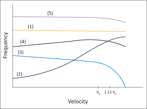
FIGURE 3: DAMPING VERSUS VELOCITY - Method 1
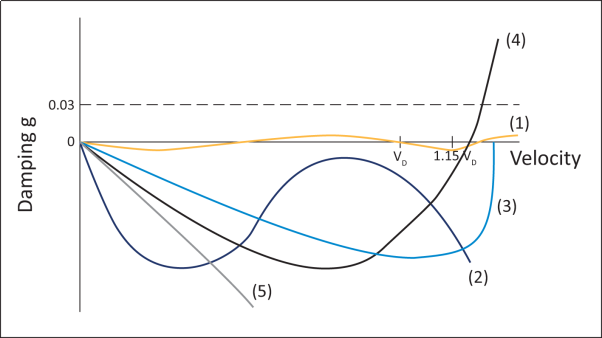
FIGURE 4: DAMPING VERSUS VELOCITY - Method 2
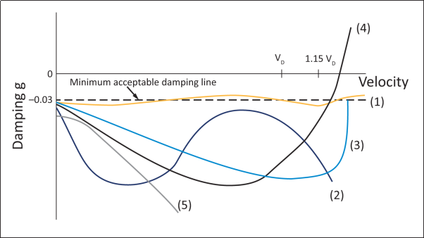
5.1.4. Analysis Considerations. Airframe aeroelastic stability analyses may be used to verify the design with respect to the structural stiffness, mass, fuel (including in-flight fuel management), automatic flight control system characteristics, and altitude and Mach number variations within the design flight envelope. The complete aeroplane should be considered as composed of lifting surfaces and bodies, including all primary control surfaces which can interact with the lifting surfaces to affect flutter stability. Control surface flutter can occur in any speed regime and has historically been the most common form of flutter. Lifting surface flutter is more likely to occur at high dynamic pressure and at high subsonic and transonic Mach numbers. Analyses are necessary to establish the mass balance and/or stiffness and redundancy requirements for the control surfaces and supporting structure and to determine the basic surface flutter trends. The analyses may be used to determine the sensitivity of the nominal aircraft design to aerodynamic, mass, and stiffness variations. Sources of stiffness variation may include the effects of skin buckling at limit load factor, air entrapment in hydraulic actuators, expected levels of in-service free play, and control system components which may include elements with non-linear stiffness. Mass variations include the effects of fuel density and distribution, control surface repairs and painting, and water and ice accumulation.
5.1.4.1. Control Surfaces. Control surface aeroelastic stability analyses should include control surface rotation, tab rotation (if applicable), significant modes of the aeroplane, control surface torsional degrees-of-freedom, and control surface bending (if applicable). Analyses of aeroplanes with tabs should include tab rotation that is both independent and related to the parent control surface. Control surface rotation frequencies should be varied about nominal values as appropriate for the condition. The control surfaces should be analysed as completely free in rotation unless it can be shown that this condition is extremely improbable. All conditions between stick-free and stick-fixed should be investigated. Free play effects should be incorporated to account for any influence of in-service wear on flutter margins. The aerodynamic coefficients of the control surface and tab used in the aeroelastic stability analysis should be adjusted to match experimental values at zero frequency. Once the analysis has been conducted with the nominal, experimentally adjusted values of hinge moment coefficients, the analysis should be conducted with parametric variations of these coefficients and other parameters subject to variability. If aeroelastic stability margins are found to be sensitive to these parameters, then additional verification in the form of model or flight tests may be required.
5.1.4.2. Mass Balance.
(a) The magnitude and spanwise location of control surface balance weights may be evaluated by analysis and/or wind tunnel flutter model tests. If the control surface torsional degrees of freedom are not included in the analysis, then adequate separation needs to be maintained between the frequency of the control surface first torsion mode and the flutter mode.
(b) Control surface unbalance tolerances should be specified to provide for repair and painting. The accumulation of water, ice, and/or dirt in or near the trailing edge of a control surface should be avoided. Free play between the balance weight, the support arm, and the control surface should not be allowed. Control surface mass properties (weight and static unbalance) should be confirmed by measurement before ground vibration testing.
(c) The balance weights and their supporting structure should be substantiated for the extreme load factors expected throughout the design flight envelope. If the absence of a rational investigation, the following limit accelerations, applied through the balance weight centre of gravity should be used.
— 100g normal to the plane of the surface
— 30g parallel to the hinge line
— 30g in the plane of the surface and perpendicular to the hinge line
5.1.4.3. Passive Flutter Dampers. Control surface passive flutter dampers may be used to prevent flutter in the event of failure of some element of the control surface actuation system or to prevent control surface buzz. Flutter analyses and/or flutter model wind tunnel tests may be used to verify adequate damping. Damper support structure flexibility should be included in the determination of adequacy of damping at the flutter frequencies. Any single damper failure should be considered. Combinations of multiple damper failures should be examined when not shown to be extremely improbable. The combined free play of the damper and supporting elements between the control surface and fixed surfaces should be considered. Provisions for in-service checks of damper integrity should be considered. Refer to paragraph 4.3 above for conditions to consider where a control surface actuator is switched to the role of an active or passive damping element of the flight control system.
5.1.4.4. Intersecting Lifting Surfaces. Intersecting lifting surface aeroelastic stability characteristics are more difficult to predict accurately than the characteristics of planar surfaces such as wings. This is due to difficulties both in correctly predicting vibration modal characteristics and in assessing those aerodynamic effects which may be of second order importance on planar surfaces, but are significant for intersecting surfaces. Proper representation of modal deflections and unsteady aerodynamic coupling terms between surfaces is essential in assessing the aeroelastic stability characteristics. The in-plane forces and motions of one or the other of the intersecting surfaces may have a strong effect on aeroelastic stability; therefore, the analysis should include the effects of steady flight forces and elastic deformations on the in-plane effects.
5.1.4.5. Ice Accumulation. Aeroelastic stability analyses should use the mass distributions derived from ice accumulations up to and including those that can accrete in the applicable icing conditions in Appendices C and O to CS-25. This includes any accretions that could develop on control surfaces. The analyses need not consider the aerodynamic effects of ice shapes. For aeroplanes approved for operation in icing conditions, all of the CS-25 Appendix C icing conditions and the Appendix O icing conditions for which certification is sought are applicable. For aeroplanes not approved for operation in icing conditions, all of the Appendix C and O icing conditions are applicable since the inadvertent encounter discussed in paragraph 3.2.3 of this AMC can occur in any icing condition. For all aeroplanes, the ice accumulation determination should take into account the ability to detect the ice and, if appropriate, the time required to leave the icing condition.
For showing compliance with the CS-25 specifications relative to SLD icing conditions represented by Appendix O, the applicant may use a comparative analysis. AMC 25.1420(f) provides guidance for comparative analysis.
5.1.4.6. Whirl Flutter.
(a) The evaluation of the aeroelastic stability should include investigations of any significant elastic, inertial, and aerodynamic forces, including those associated with rotations and displacements in the plane of any turbofan or propeller, including propeller or fan blade aerodynamics, powerplant flexibilities, powerplant mounting characteristics, and gyroscopic coupling.
(b) Failure conditions are usually significant for whirl instabilities. Engine mount, engine gear box support, or shaft failures which result in a node line shift for propeller hub pitching or yawing motion are especially significant.
(c) A wind tunnel test with a component flutter model, representing the engine/propeller system and its support system along with correlative vibration and flutter analyses of the flutter model, may be used to demonstrate adequate stability of the nominal design and failed conditions.
5.1.4.7. Automatic Control Systems. Aeroelastic stability analyses of the basic configuration should include simulation of any control system for which interaction may exist between the sensing elements and the structural modes. Where structural/control system feedback is a potential problem the effects of servo-actuator characteristics and the effects of local deformation of the servo mount on the feedback sensor output should be included in the analysis. The effect of control system failures on the aeroplane aeroelastic stability characteristics should be investigated. Failures which significantly affect the system gain and/or phase and are not shown to be extremely improbable should be analysed.
5.2. Testing. The aeroelastic stability certification test programme may consist of ground tests, flutter model tests, and flight flutter tests. Ground tests may be used for assessment of component stiffness and for determining the vibration modal characteristics of aircraft components and the complete airframe. Flutter model testing may be used to establish flutter trends and validate aeroelastic stability boundaries in areas where unsteady aerodynamic calculations require confirmation. Full scale flight flutter testing provides final verification of aeroelastic stability. The results of any of these tests may be used to provide substantiation data, to verify and improve analytical modelling procedures and data, and to identify potential or previously undefined problem areas.
5.2.1. Structural Component Tests. Stiffness tests or ground vibration tests of structural components are desirable to confirm analytically predicted characteristics and are necessary where stiffness calculations cannot accurately predict these characteristics. Components should be mounted so that the mounting characteristics are well defined or readily measurable.
5.2.2. Control System Component Tests. When reliance is placed on stiffness or damping to prevent aeroelastic instability, the following control system tests should be conducted. If the tests are performed off the aeroplane the test fixtures should reflect local attachment flexibility.
(i) Actuators for primary flight control surfaces and flutter dampers should be tested with their supporting structure. These tests are to determine the actuator/support structure stiffness for nominal design and failure conditions considered in the fail-safe analysis.
(ii) Flutter damper tests should be conducted to verify the impedance of damper and support structure. Satisfactory installed damper effectiveness at the potential flutter frequencies should, however, be assured. The results of these tests can be used to determine a suitable, in-service maintenance schedule and replacement life of the damper. The effects of allowable in-service free play should be measured.
5.2.3. Ground vibration Tests.
5.2.3.1. Ground vibration tests (GVT) or modal response tests are normally conducted on the complete conforming aeroplane. A GVT may be used to check the mathematical structural model. Alternatively, the use of measured modal data alone in aeroelastic stability analyses, instead of analytical modal data modified to match test data, may be acceptable provided the accuracy and completeness of the measured modal data is established. Whenever structural modifications or inertia changes are made to a previously certified design or a GVT validated model of the basic aeroplane, a GVT may not be necessary if these changes are shown not to affect the aeroelastic stability characteristics.
5.2.3.2. The aeroplane is best supported such that the suspended aeroplane rigid body modes are effectively uncoupled from the elastic modes of the aeroplane. Alternatively, a suspension method may be used that couples with the elastic aeroplane provided that the suspension can be analytically de-coupled from the aeroplane structure in the vibration analysis. The former suspension criterion is preferred for all ground vibration tests and is necessary in the absence of vibration analysis.
5.2.3.3. The excitation method needs to have sufficient force output and frequency range to adequately excite all significant resonant modes. The effective mass and stiffness of the exciter and attachment hardware should not distort modal response. More than one exciter or exciter location may be necessary to insure that all significant modes are identified. Multiple exciter input may be necessary on structures with significant internal damping to avoid low response levels and phase shifts at points on the structure distant from the point of excitation. Excitation may be sinusoidal, random, pseudo-random, transient, or other short duration, non stationary means. For small surfaces the effect of test sensor mass on response frequency should be taken into consideration when analysing the test results.
5.2.3.4. The minimum modal response measurement should consist of acceleration (or velocity) measurements and relative phasing at a sufficient number of points on the aeroplane structure to accurately describe the response or mode shapes of all significant structural modes. In addition, the structural damping of each mode should be determined.
5.2.4. Flutter Model Tests.
5.2.4.1. Dynamically similar flutter models may be tested in the wind tunnel to augment the flutter analysis. Flutter model testing can substantiate the flutter margins directly or indirectly by validating analysis data or methods. Some aspects of flutter analysis may require more extensive validation than others, for example control surface aerodynamics, T-tails and other configurations with aerodynamic interaction and compressibility effects. Flutter testing may additionally be useful to test configurations that are impractical to verify in flight test., such as fail-safe conditions or extensive store configurations. In any such testing, the mounting of the model and the associated analysis should be appropriate and consistent with the study being performed.
5.2.4.2. Direct substantiation of the flutter margin (clearance testing) implies a high degree of dynamic similitude. Such a test may be used to augment an analysis and show a configuration flutter free throughout the expanded design envelope. All the physical parameters which have been determined to be significant for flutter response should be appropriately scaled. These will include elastic and inertia properties, geometric properties and dynamic pressure. If transonic effects are important, the Mach number should be maintained.
5.2.4.3. Validation of analysis methods is another appropriate use of wind tunnel flutter testing. When the validity of a method is uncertain, correlation of wind tunnel flutter testing results with a corresponding analysis may increase confidence in the use of the analytical tool for certification analysis. A methods validation test should simulate conditions, scaling and geometry appropriate for the intended use of the analytical method.
5.2.4.4. Trend studies are an important use of wind tunnel flutter testing. Parametric studies can be used to establish trends for control system balance and stiffness, fuel and payload variations, structural compliances and configuration variations. The set of physical parameters requiring similitude may not be as extensive to study parametric trends as is required for clearance testing. For example, an exact match of the Mach number may not be required to track the effects of payload variations on a transonic aeroplane.
5.2.5. Flight Flutter Tests.
5.2.5.1. Full scale flight flutter testing of an aeroplane configuration to VDF/MDF is a necessary part of the flutter substantiation. An exception may be made when aerodynamic, mass, or stiffness changes to a certified aeroplane are minor, and analysis or ground tests show a negligible effect on flutter or vibration characteristics. If a failure, malfunction, or adverse condition is simulated during a flight test, the maximum speed investigated need not exceed VFC/MFC if it is shown, by correlation of the flight test data with other test data or analyses, that the requirements of CS 25.629(b)(2) are met.
5.2.5.2. Aeroplane configurations and control system configurations should be selected for flight test based on analyses and, when available, model test results. Sufficient test conditions should be performed to demonstrate aeroelastic stability throughout the entire flight envelope for the selected configurations.
5.2.5.3. Flight flutter testing requires excitation sufficient to excite the modes shown by analysis to be the most likely to couple for flutter. Excitation methods may include control surface motions or internal moving mass or external aerodynamic exciters or flight turbulence. The method of excitation should be appropriate for the modal response frequency being investigated. The effect of the excitation system itself on the aeroplane flutter characteristics should be determined prior to flight testing.
5.2.5.4. Measurement of the response at selected locations on the structure should be made in order to determine the response amplitude, damping and frequency in the critical modes at each test airspeed. It is desirable to monitor the response amplitude, frequency and damping change as VDF/MDF is approached. In demonstrating that there is no large and rapid damping reduction as VDF/MDF is approached, an endeavour should be made to identify a clear trend of damping versus speed. If this is not possible, then sufficient test points should be undertaken to achieve a satisfactory level of confidence that there is no evidence of an adverse trend.
5.2.5.5. An evaluation of phenomena not presently amenable to analyses, such as shock effects, buffet response levels, vibration levels, and control surface buzz, should also be made during flight testing.
[Amdt 25/1]
[Amdt 25/6]
[Amdt 25/16]
[Amdt 25/18]
[Amdt 25/24]
ED Decision 2016/010/R
(See AMC 25.631)
The aeroplane must be designed to assure capability of continued safe flight and landing of the aeroplane after impact with a 4 lb bird when the velocity of the aeroplane (relative to the bird along the aeroplane’s flight path) is equal to VC at sealevel or 0·85 VC at 2438 m (8000 ft), whichever is the more critical. Compliance may be shown by analysis only when based on tests carried out on sufficiently representative structures of similar design.
[Amdt 25/18]
ED Decision 2003/2/RM
Consideration should be given in the early stages of the design to the installation of items in essential services, such as control system components, and items which, if damaged, could cause a hazard, such as electrical equipment. As far as practicable, such items should not be installed immediately behind areas liable to be struck by birds.