
Filters
CS ADR-DSN.M.655 Obstacle protection surface for PAPI and APAPI
ED Decision 2022/006/R
(a)Applicability:
An obstacle protection surface should be established when it is intended to provide a visual approach slope indicator system.
(b)Characteristics:
The characteristics of the obstacle protection surface, i.e. origin, divergence, length, and slope should correspond to those specified in the relevant column of Table M-2 and in Figure M-6.
(c)New objects or extensions of existing objects should not be permitted above an obstacle protection surface except when the new object or extension would be shielded by an existing immovable object, or if after a safety assessment, it is determined that the object would not adversely affect the safety of operations of aeroplanes.
(d)Where a safety assessment indicates that an existing object extending above an obstacle protection surface could adversely affect the safety of operations of aeroplanes one or more of the following measures should be taken:
(1)remove the object;
(2)suitably raise the approach slope of the system;
(3)reduce the azimuth spread of the system so that the object is outside the confines of the beam;
(4)displace the axis of the system and its associated obstacle protection surface by no more than 5°;
(5)suitably displace the threshold; and
(6)where (5) is found to be impracticable, suitably displace the system upwind of the threshold such that the object no longer penetrates the obstacle protection surface.
Runway type/code number | ||||||||
Non-instrument | Instrument | |||||||
Code number | Code number | |||||||
Surface dimensions | 1 | 2 | 3 | 4 | 1 | 2 | 3 | 4 |
Length of inner edge | 60 m | 80 m | 150 m | 150 m | 150 m | 150 m | 300 m | 300 m |
Distance from the visual approach slope indicator system2 | D1+30 m | D1+60 m | D1+60 m | D1+60 m | D1+60 m | D1+60 m | D1+60 m | D1+60 m |
Divergence (each side) | 10 % | 10 % | 10 % | 10 % | 15 % | 15 % | 15 % | 15 % |
Total length | 7 500 m | 7 500 m | 15 000 m | 15 000 m | 7 500 m | 7 500 m | 15 000 m | 15 000 m |
Slope | ||||||||
a) PAPI1 | ― | A–0.57° | A–0.57° | A–0.57° | A–0.57° | A–0.57° | A–0.57° | A–0.57° |
b) APAPI1 | A–0.9° | A–0.9° | – | – | A–0.9° | A–0.9° | – | – |
1 Angles as indicated in Figure M-5. 2D1 is the distance of the visual approach slope indicator system from threshold prior to any displacement to remedy object penetration of the obstacle protection surface (refer to Figure M-4). The start of the obstacle protection surface is fixed to the visual approach slope indicator system location, such that displacement of the PAPI results in an equal displacement of the start of the obstacle protection surface. | ||||||||
Table M-2. Dimensions and slopes of the obstacle protection surface
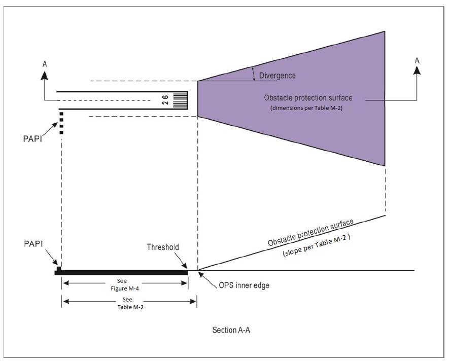
Figure M-6. Obstacle protection surface for visual approach slope indicator systems
[Issue: ADR-DSN/3]
[Issue: ADR-DSN/4]
[Issue: ADR-DSN/6]
GM1 ADR-DSN.M.655 Obstacle protection surface for PAPI and APAPI
ED Decision 2017/021/R
(a)The displacement of the system upwind of the threshold reduces the operational landing distance.
(b)Additional guidance on the calculation for siting PAPI/ APAPI on a runway with ILS/MLS is given in ICAO Doc 9157, Aerodrome Design Manual, Part 4, Visual Aids.
[Issue: ADR-DSN/4]
CS ADR-DSN.M.660 Circling guidance lights
ED Decision 2016/027/R
(a)Applicability: Circling guidance lights should be provided when existing approach and runway lighting systems do not satisfactorily permit identification of the runway and/or approach area to a circling aircraft intending to carry out circling approaches.
(b)Location and positioning:
(1)The location and number of circling guidance lights should be adequate to enable a pilot, as appropriate, to:
(i)join the downwind leg or align and adjust the aircraft’s track to the runway at a required distance from it and to distinguish the threshold in passing; and
(ii)keep in sight the runway threshold and/or other features which should make it possible to judge the turn on to base leg and final approach, taking into account the guidance provided by other visual aids.
(2)Circling guidance lights should consist of:
(i)lights indicating the extended centre line of the runway and/or parts of any approach lighting system; or
(ii)lights indicating the position of the runway threshold; or
(iii)lights indicating the direction or location of the runway;
or a combination of such lights as is appropriate to the runway under consideration.
(c)Characteristics:
(1)Circling guidance lights should be fixed or flashing lights of an intensity and beam spread adequate for the conditions of visibility and ambient light in which it is intended to make visual circling approaches. The flashing lights should be white, and the steady lights either white or gaseous discharge lights.
(2)The lights should be designed and be installed in such a manner that they should not dazzle or confuse a pilot when approaching to land, taking off, or taxiing.
[Issue: ADR-DSN/3]
GM1 ADR-DSN.M.660 Circling guidance lights
ED Decision 2014/013/R
intentionally left blank
CS ADR-DSN.M.665 Runway lead-in lighting systems
ED Decision 2017/021/R
(a)Applicability: A runway lead-in lighting system should be provided to avoid hazardous terrain.
(b)Location and positioning
(1)A runway lead-in lighting system should consist of groups of lights positioned:
(i)so as to define the desired approach path. Runway lead-in lighting systems may be curved, straight, or a combination thereof; and
(ii)so that one group should be sighted from the preceding group.
(2)The interval between adjacent groups should not exceed approximately 1 600 m.
(3)A runway lead-in lighting system should extend from a determined point up to a point where the approach lighting system if provided, or the runway lighting system is in view.
(4)Each group of lights of a runway lead-in lighting system should consist of at least three flashing lights in a linear or cluster configuration. The system should be augmented by steady burning lights where such lights would assist in identifying the system.
(c)Characteristics: The flashing lights and the steady burning lights should be white.
[Issue: ADR-DSN/4]
GM1 ADR-DSN.M.665 Runway lead-in lighting systems
ED Decision 2014/013/R
(a)Applicability: A runway lead-in lighting system may be provided for purposes of noise abatement routing.
(b)Characteristics:
(1)Where practicable, the flashing lights in each group should flash in sequence towards the runway.
(2)The path of the system may be segmented, straight, or a combination thereof, as required.
(3)The starting point of the path may be at a point within easy visual range of a final approach fix.
CS ADR-DSN.M.670 Runway threshold identification lights
ED Decision 2017/021/R
(a)Applicability:
(1)The inclusion of specifications for runway threshold identification lights is not intended to imply that the runway threshold identification lights have to be provided at an aerodrome.
(2)Where provided, runway threshold identification lights should be installed:
(i)at the threshold of a non-precision approach runway when additional threshold conspicuity is necessary or where it is not practicable to provide other approach lighting aids; and
(ii)where a runway threshold is permanently displaced from the runway extremity or temporarily displaced from the normal position and additional threshold conspicuity is necessary.
(b)Location: Runway threshold identification lights should be located symmetrically about the runway centre line, in line with the threshold and approximately 10 m outside each line of runway edge lights.
(c)Characteristics:
(1)Runway threshold identification lights should be flashing white lights with a flash frequency between 60 and 120 per minute;
(2)The lights should be visible only in the direction of approach to the runway.
[Issue: ADR-DSN/4]
GM1 ADR-DSN.M.670 Runway threshold identification lights
ED Decision 2017/021/R
intentionally left blank
[Issue: ADR-DSN/4]
CS ADR-DSN.M.675 Runway edge lights
ED Decision 2017/021/R
(a)Applicability:
(1)Runway edge lights should be provided for a runway intended for use at night or for a precision approach runway intended for use by day or night.
(2)Runway edge lights should be provided on a runway intended for take-off with an operating minimum below an RVR of the order of 800 m by day.
(b)Location and positioning:
(1)Runway edge lights should be placed along the full length of the runway and should be in two parallel rows equidistant from the centre line.
(2)Runway edge lights should be placed along the edges of the area declared for use as the runway or outside the edges of the area at a distance of not more than 3 m.
(3)Where the width of the area which could be declared as runway, exceeds 60 m, the distance between the rows of lights should be determined taking into account the nature of the operations, the light distribution characteristics of the runway edge lights, and other visual aids serving the runway.
(4)The lights should be uniformly spaced in rows at intervals of not more than 60 m for an instrument runway, and at intervals of not more than 100 m for a non-instrument runway. The lights on opposite sides of the runway axis should be on lines at right angles to that axis. At intersections of runways, lights may be spaced irregularly or omitted, provided that adequate guidance remains available to the pilot.
(c)Characteristics:
(1)Runway edge lights should be fixed lights showing variable white, except that:
(i)in the case of a displaced threshold, the lights between the beginning of the runway and the displaced threshold should show red in the approach direction; and
(ii)a section of the lights 600 m or one-third of the runway length, whichever is the less, at the remote end of the runway from the end at which the take-off run is started, should show yellow.
(2)The runway edge lights should show at all angles in azimuth necessary to provide guidance to a pilot landing or taking off in either direction. When the runway edge lights are intended to provide circling guidance, they should show at all angles in azimuth.
(d)In all angles of azimuth, as prescribed in paragraph (c)(2) above, runway edge lights should show at angles up to 15° above the horizontal with intensity adequate for the conditions of visibility and ambient light in which use of the runway for take-off or landing is intended. In any case, the intensity should be at least 50 cd except that at an aerodrome without extraneous lighting the intensity of the lights may be reduced to not less than 25 cd to avoid dazzling the pilot.
(e)Runway edge lights characteristics on a precision approach runway should be in accordance with the specifications in CS ADR-DSN.U.940, Figure U-13 or Figure U-14, as appropriate.
(f)The chromaticity of lights should be in accordance with the specifications in CS ADR-DSN.U.930 and in Figure U-1A or U-1B, as appropriate.
[Issue: ADR-DSN/3]
[Issue: ADR-DSN/4]
GM1 ADR-DSN.M.675 Runway edge lights
ED Decision 2014/013/R
intentionally left blank
CS ADR-DSN.M.680 Runway threshold and wing bar lights
ED Decision 2017/021/R
(a)Applicability of runway threshold: Runway threshold lights should be provided for a runway equipped with runway edge lights, except on a non-instrument or non-precision approach runway where the threshold is displaced and wing bar lights are provided.
(b)Location and positioning of runway threshold:
(1)When a threshold is at the extremity of a runway, the threshold lights should be placed in a row at right angles to the runway axis as near to the extremity of the runway as possible and, in any case, not more than 3 m outside the extremity.
(2)When a threshold is displaced from the extremity of a runway, threshold lights should be placed in a row at right angles to the runway axis at the displaced threshold.
(3)Threshold lighting should consist of:
(i)on a non-instrument or non-precision approach runway, at least six lights;
(ii)on a precision approach runway Category I, at least the number of lights that would be required if the lights were uniformly spaced at intervals of 3 m between the rows of runway edge lights; and
(iii)on a precision approach runway Category II or III, lights uniformly spaced between the rows of runway edge lights at intervals of not more than 3 m.
(4)The lights prescribed in paragraphs (b)(3)(i) and (b)(3)(ii) above should be either:
(i)equally spaced between the rows of runway edge lights, or
(ii)symmetrically disposed about the runway centre line in two groups, with the lights uniformly spaced in each group and with a gap between the groups equal to the gauge of the touchdown zone marking or lighting, where such is provided, or otherwise not more than half the distance between the rows of runway edge lights.
(c)Applicability of wing bar lights:
(1)Wing bar lights should be provided on a precision approach runway when additional conspicuity is considered desirable.
(2)Wing bar lights should be provided on a non-instrument or non-precision approach runway where the threshold is displaced and runway threshold lights are required, but are not provided.
(d)Location and positioning of wing bar lights: Wing bar lights should be symmetrically disposed about the runway centre line at the threshold in two groups, i.e. wing bars. Each wing bar should be formed by at least five lights extending at least 10 m outward from, and at right angles to, the line of the runway edge lights, with the innermost light of each wing bar in the line of the runway edge lights.
(e)Characteristics of runway threshold and wing bar lights:
(1)Runway threshold and wing bar lights should be fixed unidirectional lights showing green in the direction of approach to the runway. The intensity and beam spread of the lights should be adequate for the conditions of visibility and ambient light in which use of the runway is intended.
(2)Runway threshold lights on a precision approach runway should be in accordance with the specifications in CS ADR-DSN.U.940, Figure U-7.
(3)Threshold wing bar lights on a precision approach runway should be in accordance with the specifications in CS ADR-DSN.U.940, Figure U-8.
(4)The chromaticity of lights should be in accordance with the specifications in CS ADR-DSN.U.930 and Figure U-1A or U-1B, as appropriate.
[Issue: ADR-DSN/3]
[Issue: ADR-DSN/4]
GM1 ADR-DSN.M.680 Runway threshold and wing bar lights
ED Decision 2014/013/R
intentionally left blank
CS ADR-DSN.M.685 Runway end lights
ED Decision 2017/021/R
(a)Applicability: Runway end lights should be provided for a runway equipped with runway edge lights.
(b)Location and positioning:
(1)Runway end lights should be placed on a line at right angles to the runway axis as near to the end of the runway as possible and, in any case, not more than 3 m outside the end.
(2)Runway end lighting should consist of at least six lights. The lights should be either:
(i)equally spaced between the rows of runway edge lights; or
(ii)symmetrically disposed about the runway centre line in two groups with the lights uniformly spaced in each group and with a gap between the groups of not more than half the distance between the rows of runway edge lights.
(3)For a precision approach runway Category III, the spacing between runway end lights, except between the two innermost lights if a gap is used, should not exceed 6 m.
(c)Characteristics of runway end lights:
(1)Runway end lights should be fixed unidirectional lights showing red in the direction of the runway. The intensity and beam spread of the lights should be adequate for the conditions of visibility and ambient light in which use of the runway is intended.
(2)Runway end lights characteristics on a precision approach runway should be in accordance with the specifications in CS ADR-DSN.U.940, Figure U-12.
(3)Runway end lights on a precision approach runway should be in accordance with the chromaticity specifications in CS ADR-DSN.U.930 and Figure U-1A or U-1B, as appropriate.
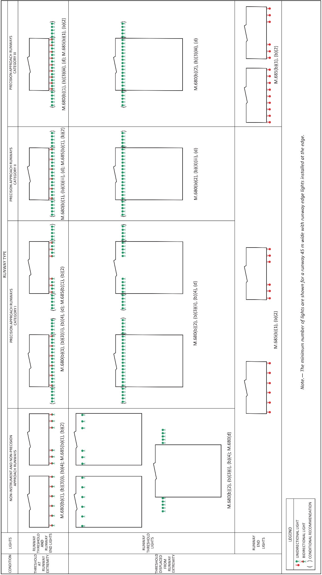
Figure M-7. Arrangement of runway threshold and runway end lights
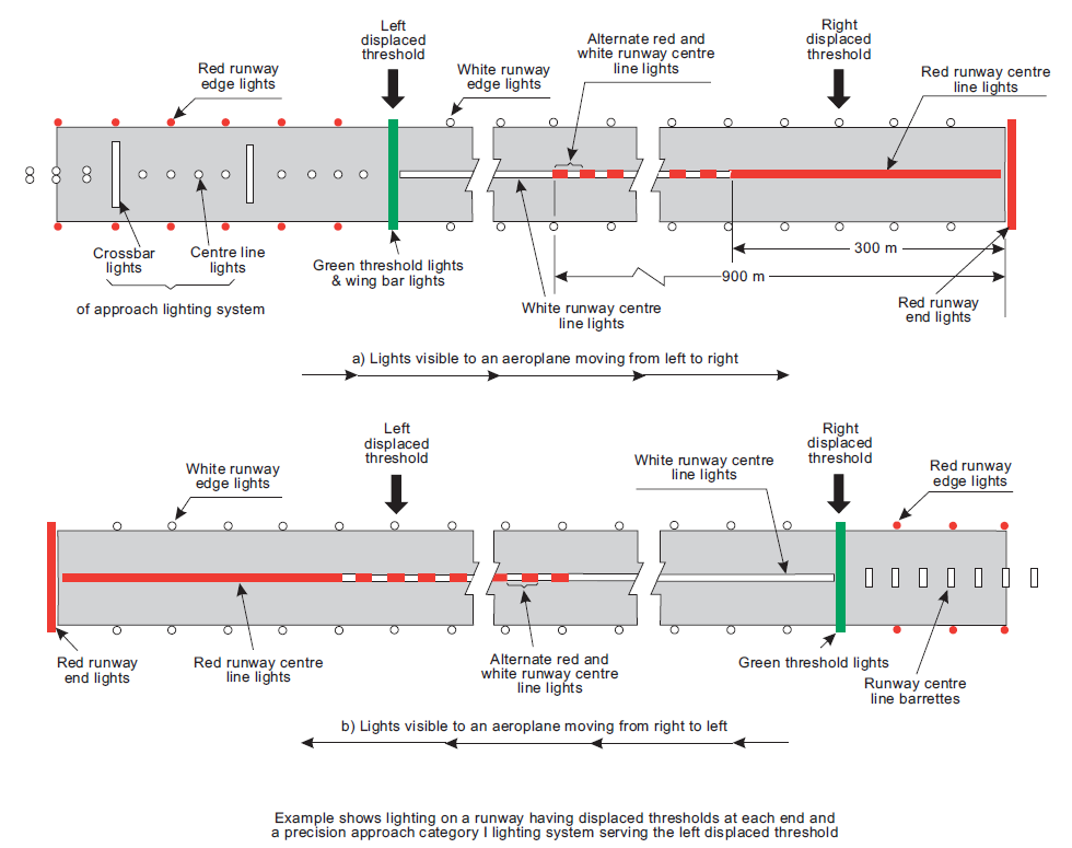
Figure M-8. Example of approach and runway lighting for runway with displaced thresholds
[Issue: ADR-DSN/3]
[Issue: ADR-DSN/4]
GM1 ADR-DSN.M.685 Runway end lights
ED Decision 2014/013/R
When the threshold is at the runway extremity, fittings serving as threshold lights may be used as runway end lights.
CS ADR-DSN.M.690 Runway centre line lights
ED Decision 2022/006/R
(a)The safety objective of runway centre line lights is to facilitate safe take-off and landing.
(b)Applicability:
(1)Runway centre line lights should be provided on a precision approach runway Category II or III.
(2)Runway centre line lights should be provided on a runway intended to be used for take-off with an operating minimum below an RVR of the order of 400 m.
(c)Location: Runway centre line lights should be located along the centre line of the runway, except that the lights may be uniformly offset to the same side of the runway centre line by not more than 60 cm where it is not practicable to locate them along the centre line. The lights should be located from the threshold to the end at longitudinal spacing of approximately 15 m. Where the serviceability level of the runway centre line lights specified as maintenance objectives in ADR.OPS.C.015(b)(1) to (b)(3) can be demonstrated, and the runway is intended for use in runway visual range conditions of 350 m or greater, the longitudinal spacing may be approximately 30 m.
(d)Characteristics:
(1)Runway centre line lights should be fixed lights showing variable white from the threshold to the point 900 m from the runway end; alternate red and variable white from 900 m to 300 m from the runway end; and red from 300 m to the runway end, except that for runways less than 1 800 m in length, the alternate red and variable white lights should extend from the midpoint of the runway usable for landing to 300 m from the runway end.
(2)Runway centre line lights characteristics should be in accordance with the specifications in CS ADR-DSN.U.940, Figure U-10 or Figure U-11, as appropriate.
(3)Runway centre line lights chromaticity should be in accordance with the specifications in CS ADR-DSN.U.930 and Figure U-1A or U-1B, as appropriate.
(e)Centre line guidance for take-off from the beginning of a runway to a displaced threshold should be provided by:
(1)an approach lighting system if its characteristics and intensity settings afford the guidance required during take-off, and it does not dazzle the pilot of an aircraft taking off; or
(2)runway centre line lights; or
(3)barrettes of at least 3 m length, and spaced at uniform intervals of 30 m, as shown in Figure M-8, designed so that their photometric characteristics and intensity setting afford the guidance required during take-off without dazzling the pilot of an aircraft taking off.
Where necessary, provision should be made to extinguish those centre line lights, as prescribed in paragraph (2) above or reset the intensity of the approach lighting system or barrettes when the runway is being used for landing. In no case should only the single source runway centre line lights show from the beginning of the runway to a displaced threshold when the runway is being used for landing.
[Issue: ADR-DSN/3]
[Issue: ADR-DSN/4]
[Issue: ADR-DSN/5]
[Issue: ADR-DSN/6]
GM1 ADR-DSN.M.690 Runway centre line lights
ED Decision 2017/021/R
(a)Runway centre line lights should be provided on a precision approach runway Category I when the runway is used by aircraft with high landing speeds or where the width between the runway edge lights is greater than 50 m.
(b)Runway centre line lights should be provided on a runway intended to be used for take-off with an operating minimum of an RVR of the order of 400 m or higher when used by aeroplanes with a very high take-off speed where the width between the runway edge lights is greater than 50 m.
(c)Consideration should be given to providing runway centre line lights where additional conspicuity is required (such as local environment, weather conditions, operational provisions and minima).
[Issue: ADR-DSN/3]
[Issue: ADR-DSN/4]
CS ADR-DSN.M.695 Runway touchdown zone lights
ED Decision 2017/021/R
(a)Applicability: Touchdown zone lights should be provided in the touchdown zone of a precision approach runway Category II or III.
(b)Location and positioning:
(1)Touchdown zone lights should extend from the threshold for a longitudinal distance of 900 m, except that, on runways less than 1 800 m in length, the system should be shortened so that it does not extend beyond the midpoint of the runway.
(2)The pattern should be formed by pairs of barrettes symmetrically located about the runway centre line. The lateral spacing between the innermost lights of a pair of barrettes should be equal to the lateral spacing selected for the touchdown zone marking. The longitudinal spacing between pairs of barrettes should be either 30 m or 60 m.
(c)Characteristics:
(1)A barrette should be composed of at least three lights with spacing between the lights of not more than 1.5 m.
(2)A barrette should be not less than 3 m or more than 4.5 m in length.
(3)Touchdown zone lights should be fixed unidirectional lights showing variable white.
(4)Touchdown zone lights characteristics should be in accordance with the specifications in CS ADR-DSN.U.940, Figure U-9.
(5)Touchdown zone lights chromaticity should be in accordance with the specifications in CS ADR-DSN.U.930 and Figure U-1A or U-1B, as appropriate.
[Issue: ADR-DSN/3]
[Issue: ADR-DSN/4]
GM1 ADR-DSN.M.695 Runway touchdown zone lights
ED Decision 2014/013/R
To allow for operations at lower visibility minima, it may be advisable to use a 30 m longitudinal spacing between barrettes.
CS ADR-DSN.M.696 Simple touchdown zone lights
ED Decision 2017/021/R
(a)The purpose of simple touchdown zone lights is to provide pilots with enhanced situational awareness in all visibility conditions and to help enable pilots to decide whether to commence a go around if the aircraft has not landed by a certain point on the runway.
(b)Applicability: Except where touchdown zone lights are provided in accordance with CS ADR-DSN.M.695, at a runway where the approach angle is greater than 3.5 degrees and/or the Landing Distance Available combined with other factors increases the risk of an overrun, simple touchdown zone lights should be provided.
(c)Location and positioning:
(1)Simple touchdown zone lights should be a pair of lights located on each side of the runway centre line 0.3 metres beyond the upwind edge of the final touchdown zone marking.
(2)The lateral spacing between the inner lights of the two pairs of lights should be equal to the lateral spacing selected for the touchdown zone marking.
(3)The spacing between the lights of the same pair should not be more than 1.5 m or half the width of the touchdown zone marking, whichever is greater (see Figure M-8(C)).
(4)Where provided on a runway without touchdown zone markings, simple touchdown zone lights should be installed in such a position that provides the equivalent touchdown zone information.
(d)Characteristics:
(1)Simple touchdown zone lights should be fixed unidirectional lights showing variable white and aligned so as to be visible to the pilot of a landing aeroplane in the direction of approach to the runway.
(2)Simple touchdown zone lights characteristics should be in accordance with the specifications in CS ADR-DSN.U.940, Figure U-9.
(3)Simple touchdown zone lights chromaticity should be in accordance with the specifications in CS ADR-DSN.U.930 and Figure U-1A or U-1B, as appropriate.
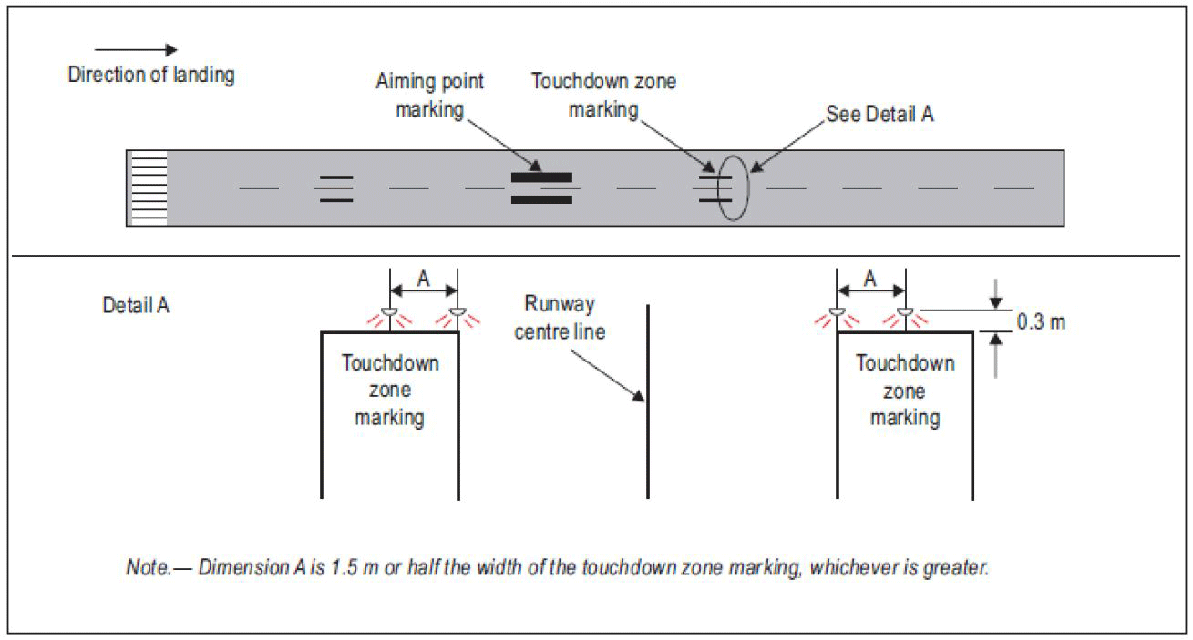
Figure M-8(C). Simple touchdown zone lighting
[Issue: ADR-DSN/3]
[Issue: ADR-DSN/4]
GM1 ADR-DSN.M.696 Simple touchdown zone lights
ED Decision 2016/027/R
(a)Simple touchdown zone lights should be supplied with power on a separate circuit to other runway lighting so that they may be used when other lighting is switched off.
[Issue: ADR-DSN/3]
CS ADR-DSN.M.700 Rapid exit taxiway indicator lights (RETILs)
ED Decision 2017/021/R
(a)Applicability:
(1)The inclusion of specifications for RETILs is not intended to imply that RETILs have to be provided at an aerodrome.
(2)Where installed, the purpose of RETILs is to provide pilots with distance-to-go information to the nearest rapid exit taxiway on the runway, to enhance situational awareness in low visibility conditions and enable pilots to apply braking action for more efficient roll-out and runway exit speeds.
(b)Location:
(1)RETILs should be located on the runway on the same side of the runway centre line as the associated rapid exit taxiway. The lights should be located 2 m apart and the light nearest to the runway centre line should be displaced 2 m from the runway centre line.
(2)Where more than one rapid exit taxiway exists on a runway, the set of RETILs for each exit should not overlap when displayed.
(c)Characteristics:
(1)RETILs are fixed lights and comprise a set of yellow unidirectional lights installed in the runway adjacent to the centre line. The lights are positioned in a 3-2-1 sequence at 100 m intervals prior to the point of tangency of the rapid exit taxiway centre line.
(2)RETILs should be supplied with power on a separate circuit to other runway lighting so that they may be used when other lighting is switched off.
(3)RETILs’ characteristics should be in accordance with the specifications in CS ADR-DSN.U.940, Figure U-10 or U-11, as appropriate.
(4)RETILs’ chromaticity should be in accordance with the specifications in CS ADR-DSN.U.930 and Figure U-1A or U-1B, as appropriate.
[Issue: ADR-DSN/4]
GM1 ADR-DSN.M.700 Rapid exit taxiway indicator lights (RETILs)
ED Decision 2017/021/R
(a)In low visibility conditions, rapid exit taxiway indicator lights provide useful situational awareness cues while allowing the pilot to concentrate on keeping the aircraft on the runway centre line.
(b)Rapid exit taxiway indicator lights should be considered on a runway intended for use in runway visual range conditions less than a value of 350 m where the traffic density is heavy.
(c)Rapid exit taxiway indicator lights should not be displayed in the event of any lamp failure or other failure that prevents the display of the light pattern depicted in Figure GM-M-3.
(d)Following a landing, runway occupancy time has a significant effect on the achievable runway capacity. Rapid exit taxiway indicator lights allow pilots to maintain a good roll-out speed until it is necessary to decelerate to an appropriate speed for the turn into a rapid exit turn-off. A roll-out speed of 60 kt until the first RETIL (three-light barrette) is reached is seen as the optimum.
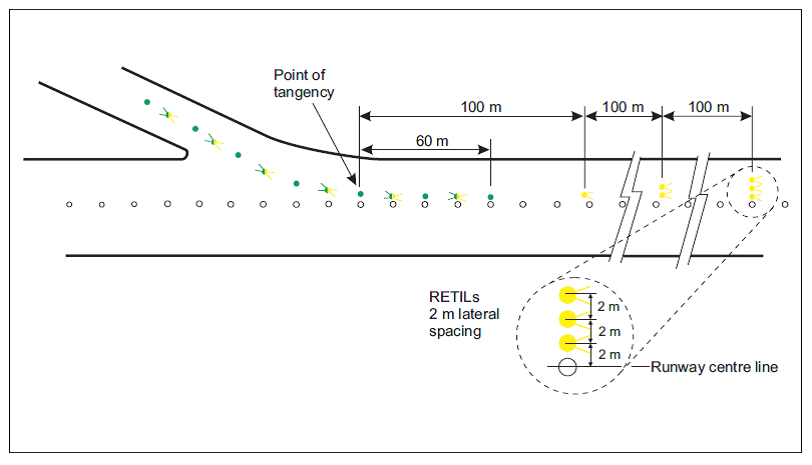
Figure GM-M-3. Rapid exit taxiway indicator lights (RETILs)
[Issue: ADR-DSN/3]
[Issue: ADR-DSN/4]
CS ADR-DSN.M.705 Stopway lights
ED Decision 2021/004/R
(a)Applicability: Stopway lights should be provided for a stopway intended for use at night, or in runway visual range conditions less than a value of 800 m.
(b)Location:
(1)Stopway lights should be placed along the full length of the stopway and should be in two parallel rows that are equidistant from the centre line and coincident with the rows of the runway edge lights. The spacing between the lights should be in accordance with CS ADR-DSN.M.675(b)(4). Stopway lights placed along the edge of the stopway should consist of at least one pair of lights.
(2)At least four uni-directional stopway lights equally spaced across the width of the stopway should be provided across the end of a stopway on a line at right angles to the stopway axis as near to the end of the stopway as possible and, in any case, not more than 3 m outside the end.
(c)Characteristics:
(1)Stopway lights should be fixed unidirectional lights showing red in the direction of the runway.
(2)Stopway lights chromaticity should be in accordance with the specifications in CS ADR-DSN.U.930 and Figure U-1A or U-1B, as appropriate.
[Issue: ADR-DSN/3]
[Issue: ADR-DSN/4]
[Issue: ADR-DSN/5]
GM1 ADR-DSN.M.705 Stopway lights
ED Decision 2014/013/R
intentionally left blank
CS ADR-DSN.M.706 Runway status lights (RWSL)
ED Decision 2017/021/R
(a)Applicability:
(1)The inclusion of detailed specification for RWSL is not intended to imply that RWSL have to be provided at an aerodrome.
(2)RWSL is a type of autonomous runway incursion warning system (see CS ADR-DSN.T.921), consisting of two basic visual components: runway entrance lights (RELs) and take-off hold lights (THLs). The two components can be installed individually, but are designed to complement each other.
(b)Location:
(1)Where provided, RELs should be offset 0.6 m from the taxiway centre line on the opposite side to the taxiway centre line lights and begin 0.6 m before the runway-holding position extending to the edge of the runway. An additional single light should be placed on the runway 0.6 m from the runway centre line and aligned with the last two taxiway RELs.
(2)RELs should consist of at least five light units and should be spaced at a minimum of 3.8 m and a maximum of 15.2 m longitudinally, depending upon the taxiway length involved, except for a single light installed near the runway centre line.
(3)Where provided, THLs should be offset 1.8 m on each side of the runway centre line lights and extend, in pairs, starting at a point 115 m from the beginning of the runway and, thereafter, every 30 m for at least 450 m.
(c)Characteristics:
(1)Where provided, RELs should consist of a single line of fixed in pavement lights showing red in the direction of aircraft approaching the runway.
(2)RELs should illuminate as an array at each taxiway/runway intersection where they are installed less than two seconds after the system determines that a warning is needed.
(3)RELs intensity and beam spread should be in accordance with the specifications of Chapter U, Figures U-16 and U-18.
(4)Where provided, THLs should consist of two rows of fixed in pavement lights showing red facing the aircraft taking off.
(5)THLs should illuminate as an array on the runway less than two seconds after the system determines that a warning is needed.
(6)THLs intensity and beam spread should be in accordance with the specifications of Chapter U, Figure U-29.
(7)RELs and THLs should be automated to the extent that the only control over each system will be to disable one or both systems.
[Issue: ADR-DSN/4]
GM1 ADR-DSN.M.706 Runway status lights (RWSLs)
ED Decision 2017/021/R
(a)Where two or more runway-holding positions are provided, the runway-holding position referred is that closest to the runway.
(b)Additional take-off hold lights (THLs) may be similarly provided at the starting point of the take-off roll.
(c)Consideration for reduced beam width may be required for some runway entrance lights (RELs) lights at acute-angled runway/taxiway intersections to ensure the RELs are not visible to aircraft on the runway.
[Issue: ADR-DSN/4]
CS ADR-DSN.M.710 Taxiway centre line lights
ED Decision 2022/006/R
(a)The safety objective of taxiway centre line lights is to provide guidance for the safe taxi of aircraft as described in paragraph (b).
(b)Applicability:
(1)Taxiway centre line lights should be provided on an exit taxiway, taxiway, de-icing/anti-icing facility, and apron intended for use in runway visual range conditions less than a value of 350 m in such a manner as to provide continuous guidance between the runway centre line and aircraft stands, except that these lights need not be provided where the traffic density is light and taxiway edge lights, and centre line marking provide adequate guidance.
(2)Taxiway centre line lights should be provided on a taxiway intended for use at night in runway visual range conditions of 350 m or greater, and particularly on complex taxiway intersections and exit taxiways, except that these lights need not be provided where taxiway edge lights, and centre line marking provide adequate guidance.
(3)Taxiway centre line lights should be provided on an exit taxiway, taxiway, de-icing/anti icing facility, and apron in all visibility conditions where specified as components of an advanced surface movement guidance and control system in such a manner as to provide continuous guidance between the runway centre line and aircraft stands.
(4)Taxiway centre line lights should be provided on a runway forming part of a standard taxi-route and intended for taxiing in runway visual range conditions less than a value of 350 m, except that these lights need not be provided where the traffic density is light and taxiway edge lights, and centre line marking provide adequate guidance.
(5)Taxiway centre line lights should be provided in all visibility conditions on a runway forming part of a standard taxi-route where specified as components of an advanced surface movement guidance and control system.
(6)Where a runway forming part of a standard taxi route is provided with runway lighting and taxiway lighting, the lighting systems should be interlocked to preclude the possibility of simultaneous operation of both forms of lighting.
(c)Characteristics:
(1)Except as provided for in paragraph (c)(3) below, taxiway centre line lights on a taxiway other than an exit taxiway and on a runway forming part of a standard taxi-route should be fixed lights showing green with beam dimensions such that the light is visible only from aeroplanes on, or in the vicinity of the taxiway.
(2)Taxiway centre line lights on an exit taxiway should be fixed lights. Alternate taxiway centre line lights should show green and yellow from their beginning near the runway centre line to the perimeter of the ILS/MLS critical/sensitive area, or the lower edge of the inner transitional surface, whichever is farthest from the runway; and thereafter all lights should show green, as shown in Figure M-10. The first light in the exit centre line should always show green and the light nearest to the perimeter should always show yellow.
(3)Where necessary to denote the proximity to a runway, taxiway centre line lights should be fixed lights showing alternating green and yellow from the perimeter of the ILS/MLS critical/sensitive area or the lower edge of the inner transitional surface, whichever is farthest from the runway, to the runway and continue alternating green and yellow until:
(i)their end point near the runway centre line; or
(ii)in the case of the taxiway centre line lights crossing the runway, to the opposite perimeter of the ILS/MLS critical/sensitive area or the lower edge of the inner transitional surface, whichever is farthest from the runway.
(4)Taxiway centre line lights should be in accordance with the specifications in
CS ADR-DSN.U.940, Figure U-16, U-17, or U-18, as appropriate, for taxiways intended for use in runway visual range conditions of less than a value of 350 m; Figure U-19 or Figure U-20, as appropriate, for other taxiways.
(5)Where higher intensities are required, from an operational point of view, taxiway centre line lights on rapid exit taxiways intended for use in runway visual range conditions less than a value of 350 m should be in accordance with the specifications in
CS ADR-DSN.U.940, Figure U-16. The number of levels of brilliancy settings for these lights should be the same as that for the runway centre line lights.
(6)Where taxiway centre line lights are specified as components of an advanced surface movement guidance and control system and where, from an operational point of view, higher intensities are required to maintain ground movements at a certain speed in very low visibilities or in bright daytime conditions, taxiway centre line lights should be in accordance with the specifications in CS ADR-DSN.U.940, Figure U-21, U-22, or U-23, as appropriate.
(7)High intensity centre line lights should only be used in case of an absolute necessity and following a specific study.
(8)Taxiway centre line lights chromaticity should be in accordance with the specifications in CS ADR-DSN.U.930 and Figure U-1A or U-1B, as appropriate.
(d)Location and positioning:
(1)Taxiway centre line lights should normally be located on the taxiway centre line marking, except that they may be offset by not more than 30 cm where it is not practicable to locate them on the marking, as shown in Figure M-9.
(2)Taxiway centre line lights on taxiways, runways, rapid exit taxiways or on other exit taxiways should be positioned in accordance with CS ADR-DSN.M.715.
[Issue: ADR-DSN/3]
[Issue: ADR-DSN/4]
[Issue: ADR-DSN/6]
GM1 ADR-DSN.M.710 Taxiway centre line lights
ED Decision 2016/027/R
(a)In the case where taxiway centre line lights are provided and where there may be a need to delineate the edges of a taxiway, e.g. on a rapid exit taxiway, narrow taxiway, or in snow conditions, this may be done with taxiway edge lights or markers. Care is necessary to limit the light distribution of green lights on or near a runway so as to avoid possible confusion with threshold lights.
(b)Care should be taken to limit the light distribution of green lights on or near a runway so as to avoid possible confusion with threshold lights.
(c)The provisions of CS ADR-DSN.M.710(c)(3) can form part of effective runway incursion prevention measures.
[Issue: ADR-DSN/3]
CS ADR-DSN.M.715 Taxiway centre line lights on taxiways, runways, rapid exit taxiways, or on other exit taxiways
ED Decision 2022/006/R
(a)The safety objective of taxiway centre line lights is to provide guidance for the safe taxi of aircraft as described in paragraph (b).
(b)Taxiway centre line lights on taxiways:
(1)Taxiway centre line lights on a straight section of a taxiway should be spaced at longitudinal intervals of not more than 30 m, except that:
(i)intervals less than 30 m should be provided on short straight sections; and
(ii)on a taxiway intended for use in RVR conditions of less than a value of 350 m, the longitudinal spacing should not exceed 15 m.
(2)Taxiway centre line lights on a taxiway curve should continue from the straight portion of the taxiway at a constant distance from the outside edge of the taxiway curve. The lights should be spaced at intervals such that a clear indication of the curve is provided.
(3)On a taxiway curve the spacing of taxiway centre line lights should be as specified in the Table M-3.
RVR | Radius of taxiway curve | Taxiway centre line lights spacing on taxiway curves |
< 350 m | < 400 m | Not greater than7.5 m. This spacing should extend for 60 m before and after the curve. |
> 400 m | Not greater than 15 m | |
> 350 m | < 400 m | Not greater than 7.5 m |
401 m to 899 m | Not greater than 15 m | |
> 900 m | Not greater than 30 m |
Table M-3. Taxiway centre line lights spacing on taxiway curves
(c)Taxiway centre line lights on rapid exit taxiways:
(1)Taxiway centre line lights on a rapid exit taxiway should commence at a point at least 60 m before the beginning of the taxiway centre line curve, and continue beyond the end of the curve to a point on the centre line of the taxiway where an aeroplane can be expected to reach normal taxiing speed, as shown in Figure M-10. The lights on that portion parallel to the runway centre line should always be at least 60 cm from any row of runway centre line lights, as shown in Figure M-9.
(2)The lights should be spaced at longitudinal intervals of not more than 15 m. Where runway centre line lights are not provided, a greater interval not exceeding 30 m may be used.
(d)Taxiway centre line lights on other exit taxiways:
(1)Taxiway centre line lights on exit taxiways other than rapid exit taxiways should commence at the point where the taxiway centre line marking begins to curve from the runway centre line, and follow the curved taxiway centre line marking at least to the point where the marking leaves the runway. The first light should be at least 60 cm from any row of runway centre line lights, as shown in Figure M-9.
(2)The lights should be spaced at longitudinal intervals of not more than 7.5 m.
(e)Taxiway centre line lights on runways: Taxiway centre line lights on a runway forming part of a standard taxi-route, and intended for taxiing in runway visual range conditions less than a value of 350 m should be spaced at longitudinal intervals not exceeding 15 m.
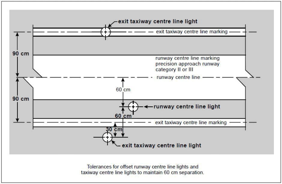
Figure M-9. Offset runway and taxiway centre line lights
(f)Positioning of taxiway centre line lights on taxiway:
The spacing on a particular section of taxiway centre line lighting (straight or curved section) should be such that a clear indication of the taxiway centre line is provided, particularly on a curved section.
(g)Taxiway centre line lights on straight sections of taxiways: Larger intervals not exceeding 60 m may be used where, because of the prevailing meteorological conditions, adequate guidance is provided by such spacing.
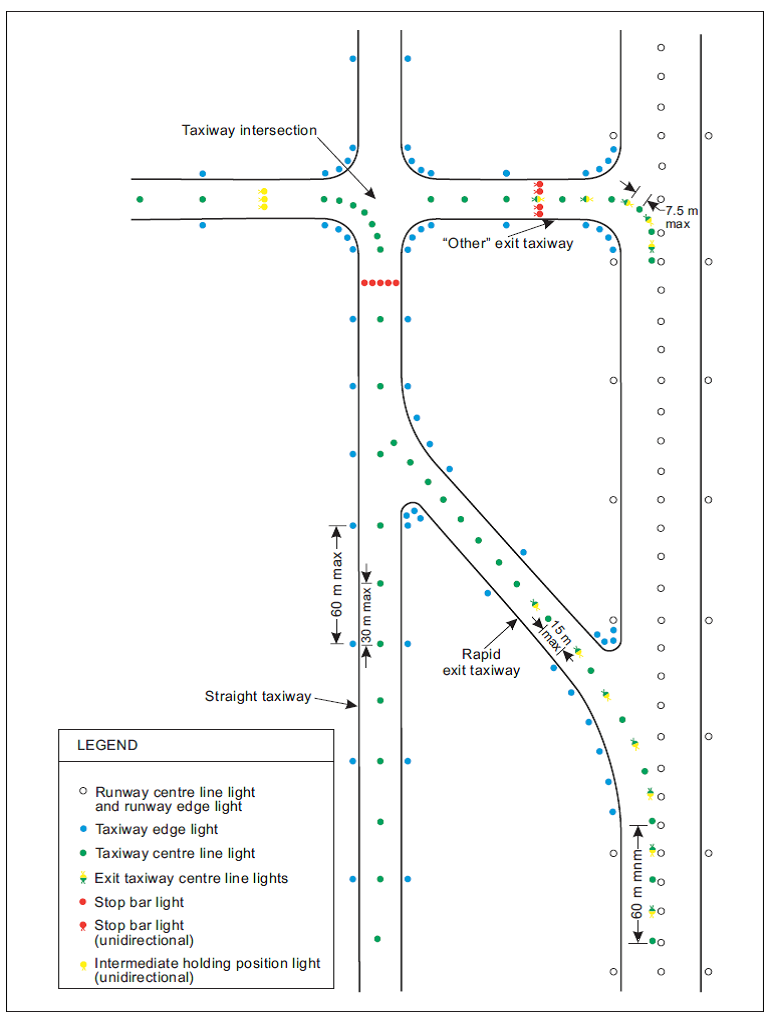
Figure M-10. Taxiway lighting
[Issue: ADR-DSN/3]
[Issue: ADR-DSN/6]
GM1 ADR-DSN.M.715 Taxiway centre line lights on taxiways, runways, rapid exit taxiways, or on other exit taxiways
ED Decision 2014/013/R
intentionally left blank
CS ADR-DSN.M.720 Taxiway edge lights
ED Decision 2017/021/R
(a)Applicability:
(1)Taxiway edge lights should be provided at the edges of a runway turn pad, holding bay, de-icing/anti-icing facility, apron, etc. intended for use at night, and on a taxiway not provided with taxiway centre line lights and intended for use at night, except that taxiway edge lights need not be provided where, considering the nature of the operations, adequate guidance can be achieved by surface illumination or other means.
(2)Taxiway edge lights should be provided on a runway forming part of a standard taxi-route and intended for taxiing at night where the runway is not provided with taxiway centre line lights.
(b)Location and positioning:
(1)Taxiway edge lights on a straight section of a taxiway and on a runway forming part of a standard taxi-route should be spaced at uniform longitudinal intervals of not more than 60 m. The lights on a curve should be spaced at intervals less than 60 m so that a clear indication of the curve is provided.
(2)Taxiway edge lights on a holding bay, de-icing/anti-icing facility, apron, etc. should be spaced at uniform longitudinal intervals of not more than 60 m.
(3)Taxiway edge lights on a runway turn pad should be spaced at uniform longitudinal intervals of not more than 30 m.
(4)The lights should be located as near as practicable to the edges of the taxiway, runway turn pad, holding bay, de-icing/anti-icing facility, apron or runway, etc., or outside the edges at a distance of not more than 3 m.
(c)Characteristics:
(1)Taxiway edge lights should be fixed lights showing blue.
(2)The lights should show up to at least 75° above the horizontal and at all angles in azimuth necessary to provide guidance to a pilot taxiing in either direction. At an intersection, exit, or curve the lights should be shielded as far as practicable so that they cannot be seen in angles of azimuth in which they may be confused with other lights.
(3)The intensity of taxiway edge lights should be at least 2 cd from 0° to 6° vertical, and 0.2 cd at any vertical angles between 6° and 75°.
(4)Taxiway edge lights chromaticity should be in accordance with the specifications in CS ADR-DSN.U.930 and Figure U-1A or U-1B, as appropriate.
[Issue: ADR-DSN/3]
[Issue: ADR-DSN/4]
GM1 ADR-DSN.M.720 Taxiway edge lights
ED Decision 2014/013/R
intentionally left blank
CS ADR-DSN.M.725 Runway turn pad lights
ED Decision 2017/021/R
(a)The safety objective of runway turn pad lights is to provide additional guidance on a runway turn pad to enable an aeroplane to complete a safe 180-degree turn, and align with the runway centre line.
(b)Applicability:
(1)Runway turn pad lights should be provided for continuous guidance on a runway turn pad intended for use in runway visual range conditions less than a value of 350 m to enable an aeroplane to complete a 180-degree turn, and align with the runway centre line.
(2)Runway turn pad lights should be provided on a runway turn pad intended for use at night, except that these lights need not be provided where taxiway edge lights and runway turn pad marking provide adequate guidance.
(c)Location:
(1)Runway turn pad lights should normally be located on the runway turn pad marking, except that they should be offset by not more than 30 cm where it is not practicable to locate them on the marking.
(2)Runway turn pad lights on a straight section of the runway turn pad marking should be spaced at longitudinal intervals of not more than 15 m.
(3)Runway turn pad lights on a curved section of the runway turn pad marking should not exceed a spacing of 7.5 m.
(d)Characteristics:
(1)Runway turn pad lights should be unidirectional fixed lights showing green with beam dimensions such that the light is visible only from aeroplanes on or approaching the runway turn pad.
(2)Runway turn pad lights should be in accordance with the specifications in CS ADR-DSN.U.940, Figure U-17 or Figure U-18, as appropriate.
(3)Runway turn pad lights chromaticity should be in accordance with the specifications in CS ADR-DSN.U.930 and Figure U-1A or U-1B, as appropriate.
[Issue: ADR-DSN/3]
[Issue: ADR-DSN/4]
GM1 ADR-DSN.M.725 Runway turn pad lights
ED Decision 2014/013/R
intentionally left blank
CS ADR-DSN.M.730 Stop bars
ED Decision 2017/021/R
(a)Applicability:
(1)A stop bar should be provided at every runway-holding position serving a runway when it is intended that the runway should be used in runway visual range conditions less than a value of 550 m, except where:
(i)appropriate aids and procedures are available to assist in preventing inadvertent incursions of traffic onto the runway; or
(ii)operational procedures exist to limit, in runway visual range conditions less than a value of 550 m, the number of:
(A)aircraft on the manoeuvring area to one at a time; and
(B)vehicles on the manoeuvring area to the essential minimum.
(2)Where there is more than one stop bar associated with a taxiway/runway intersection, only one should be illuminated at any given time.
(3)A stop bar should be provided at an intermediate holding position when it is desired to supplement markings with lights, and to provide traffic control by visual means.
(b)Location: Stop bars should be located across the taxiway at the point where it is desired that traffic stop.
(c)Characteristics:
(1)Stop bars should consist of lights spaced at uniform intervals of not more than 3 m across the taxiway, showing red in the intended direction(s) of approach to the intersection or runway-holding position.
(2)Stop bars installed at a runway-holding position should be unidirectional, and should show red in the direction of approach to the runway.
(3)The intensity in red light and beam spreads of stop bar lights should be in accordance with the specifications in CS ADR-DSN.U.940, Figures U-16 to U-20, as appropriate.
(4)Where stop bars are specified as components of an advanced surface movement guidance and control system, and where, from an operational point of view, higher intensities are required to maintain ground movements at a certain speed in very low visibilities or in bright daytime conditions, the intensity in red light and beam spreads of stop bar lights should be in accordance with the specifications in CS ADR-DSN.U.940, Figures U-21, U-22 or U-23, as appropriate.
(5)Where a wide beam fixture is required, the intensity in red light and beam spreads of stop bar lights should be in accordance with the specifications in CS ADR-DSN.U.940, Figure U-21 or Figure U-23, as appropriate.
(6)The lighting circuit should be designed so that:
(i)stop bars located across entrance taxiways are selectively switchable;
(ii)stop bars located across taxiways intended to be used only as exit taxiways are switchable selectively or in groups;
(iii)when a stop bar is illuminated, any taxiway centre line lights installed beyond the stop bar should be extinguished for a distance of at least 90 m; and
(iv)stop bars are interlocked with the taxiway centre line lights so that when the centre line lights beyond the stop bar are illuminated, the stop bar is extinguished and vice versa.
(7)Stop bar lights chromaticity should be in accordance with the specifications in CS ADR-DSN.U.930 and Figure U-1A or U-1B, as appropriate.
[Issue: ADR-DSN/3]
[Issue: ADR-DSN/4]
GM1 ADR-DSN.M.730 Stop bars
ED Decision 2016/027/R
(a)A stop bar is intended to be controlled either manually or automatically by air traffic services.
(b)Runway incursions may take place in all visibility or weather conditions. The provision of stop bars at runway-holding positions and their use at night and in visibility conditions greater than 550 m runway visual range can form part of effective runway incursion prevention measures.
(c)A pair of elevated lights should be added to each end of the stop bar where the in-pavement stop bar lights might be obscured from a pilot’s view, for example by snow or rain, or where a pilot may be required to stop the aircraft in a position so close to the lights that they are blocked from view by the structure of the aircraft.
(d)Where necessary, to enhance conspicuity of an existing stop bar, extra lights are installed uniformly.
(e)Where the additional lights specified in (c) above are provided, these lights should be located not less than 3 m from the taxiway edge.
(f)Where the additional lights specified in (c) above are provided, these lights should have the same characteristics as the lights in the stop bar but should be visible to approaching aircraft up to the stop bar position.
(g)High-intensity stop bars should only be used in case of an absolute necessity and following a specific study.
(h)Care is required in the design of the electrical system to ensure that all of the lights of a stop bar will not fail at the same time. Guidance on this issue is given in ICAO Doc 9157, Aerodrome Design Manual, Part 5, Electrical Systems.
[Issue: ADR-DSN/3]
CS ADR-DSN.M.735 Intermediate holding position lights
ED Decision 2017/021/R
(a)Applicability:
(1)Except where a stop bar has been installed, intermediate holding position lights should be provided at an intermediate holding position intended for use in runway visual range conditions less than a value of 350 m.
(2)Intermediate holding position lights should be provided at an intermediate holding position where there is no need for stop-and-go signals as provided by a stop bar.
(b)Location: Intermediate holding position lights should be located along the intermediate holding position marking at a distance of 0.3 m prior to the marking.
(c)Characteristics of intermediate holding position lights:
(1)Intermediate holding position lights should consist of three fixed unidirectional lights showing yellow in the direction of approach to the intermediate holding position with a light distribution similar to taxiway centre line lights if provided.
(2)The lights should be disposed symmetrically about and at right angle to the taxiway centre line, with individual lights spaced 1.5 m apart.
(3)Intermediate holding position lights chromaticity should be in accordance with the specifications in CS ADR-DSN.U.930 and in Figure U-1A or U-1B, as appropriate.
[Issue: ADR-DSN/3]
[Issue: ADR-DSN/4]
GM1 ADR-DSN.M.735 Intermediate holding position lights
ED Decision 2014/013/R
intentionally left blank
CS ADR-DSN.M.740 De-icing/anti-icing facility exit lights
ED Decision 2017/021/R
(a)Applicability: The purpose of the de-icing/anti-icing facility exit lights is to indicate the exit boundary of a remote de-icing/anti-icing facility adjoining a taxiway.
(b)Location: Where provided, de-icing/anti-icing facility exit lights should be located 0.3 m inward of the intermediate holding position marking displayed at the exit boundary of a remote de-icing/ anti-icing facility.
(c)Characteristics: Where provided, de-icing/anti-icing facility exit lights should consist of in-pavement fixed unidirectional lights spaced at intervals of 6 m showing yellow in the direction of the approach to the exit boundary with a light distribution similar to taxiway centre line lights (see Figure M-11).
(d)De-icing/anti-icing facility exit lights chromaticity should be in accordance with the specifications in CS ADR-DSN.U.930 and Figure U-1A or U-1B, as appropriate.
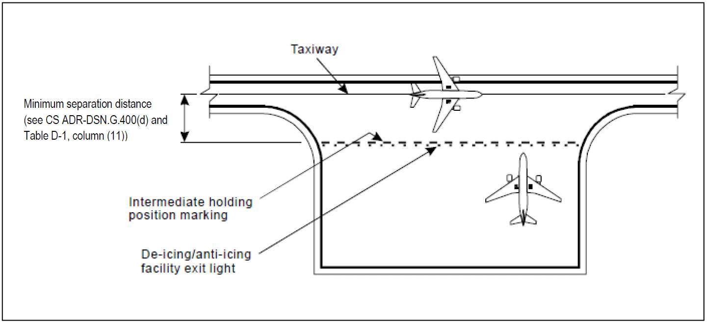
Figure M-11. Example of remote de-icing/anti-icing facility
[Issue: ADR-DSN/3]
[Issue: ADR-DSN/4]
GM1 ADR-DSN.M.740 De-icing/anti-icing facility exit lights
ED Decision 2014/013/R
intentionally left blank
CS ADR-DSN.M.745 Runway guard lights
ED Decision 2022/006/R
(a)The safety objective of the runway guard lights is to warn pilots and drivers of vehicles, when operating on taxiways, that they are about to enter a runway. There are two standard configurations of runway guard lights as illustrated in Figure M-12.
(b)Applicability:
(1)Runway guard lights, Configuration A, should be provided at each taxiway/runway intersection associated with a runway intended for use in:
(i)runway visual range conditions less than a value of 550 m where a stop bar is not installed; and
(ii)runway visual range conditions of values between 550 m and 1 200 m where the traffic density is heavy.
(2)As part of runway incursion prevention measures, runway guard lights, Configuration A or B, should be provided at each taxiway/runway intersection where runway incursion hot spots have been identified, and used under all weather conditions during day and night.
(3)Configuration B runway guard lights should not be collocated with a stop bar.
(4)Where more than one runway-holding position exists at a runway/taxiway intersection, only the set of runway guard lights associated with the operational runway-holding position should be illuminated.
(c)Location:
(1)Runway guard lights, Configuration A, should be located at each side of the taxiway within the area delimited by the inner and the outer edges of the runway holding position marking.
(2)Runway guard lights, Configuration B, should be located across the taxiway within the area delimited by the inner and the outer edges of the runway holding position marking.
(d)Characteristics:
(1)Runway guard lights, Configuration A, should consist of two pairs of yellow lights.
(2)Runway guard lights, Configuration B, should consist of yellow lights spaced at intervals of 3 m across the taxiway.
(3)The light beam should be unidirectional and should show yellow in the direction of approach to the runway-holding position.
(4)The intensity in yellow light and beam spreads of lights of Configuration A should be in accordance with the specifications in CS ADR-DSN.U.940, Figure U-27.
(5)Where runway guard lights are intended for use during the day, the intensity in yellow light and beam spreads of lights of Configuration A should be in accordance with the specifications in CS ADR-DSN.U.940, Figure U-28.
(6)Where runway guard lights are specified as components of an advanced surface movement guidance and control system where higher light intensities are required, the intensity in yellow light and beam spreads of lights of Configuration A should be in accordance with the specifications in CS ADR-DSN.U.940, Figure U-28.
(7)The intensity in yellow light and beam spreads of lights of Configuration B should be in accordance with the specifications in CS ADR-DSN.U.940, Figure U-28.
(8)Where runway guard lights are intended for use during the day, the intensity in yellow light and beam spreads of lights of Configuration B should be in accordance with the specifications in CS ADR-DSN.U.940, Figure U-24.
(9)Where runway guard lights are specified as components of an advanced surface movement guidance and control system where higher light intensities are required, the intensity in yellow light and beam spreads of lights of Configuration B should be in accordance with the specifications in CS ADR-DSN.U.940, Figure U-24.
(10)The lights in each unit of Configuration A should be illuminated alternately.
(11)For Configuration B, adjacent lights should be alternately illuminated and alternative lights should be illuminated in unison.
(12)The lights should be illuminated between 30 and 60 cycles per minute and the light suppression and illumination periods should be equal and opposite in each light.
(13)Runway guard lights chromaticity should be in accordance with the specifications in CS ADR-DSN.U.930 and Figure U-1A or U-1B, as appropriate.
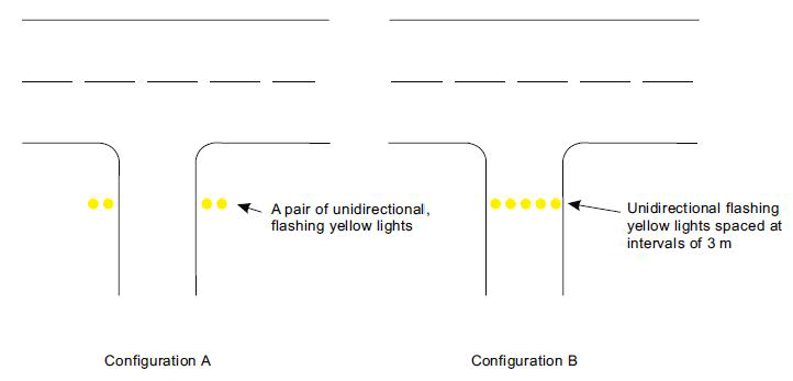
Figure M-12. Runway guard lights
[Issue: ADR-DSN/3]
[Issue: ADR-DSN/4]
[Issue: ADR-DSN/6]
GM1 ADR-DSN.M.745 Runway guard lights
ED Decision 2022/006/R
(a)Runway incursions may take place in all visibility or weather conditions. The use of runway guard lights at runway-holding positions can form part of effective runway incursion prevention measures.
(b)Where taxiways are substantially wider than those specified in CS ADR-DSN.D.245, such as widethroat taxiways, the lights in Configuration A, located at each of the sides, are likely to be missed by pilots and may be necessary to be supplemented by a row of lights (inset) located across the taxiway, Configuration B.
(c)Higher light intensities may be required to maintain ground movement at a certain speed in low visibilities.
(d)The optimum flash rate is dependent on the rise and fall times of the lamps used. Runway guard lights, Configuration A, installed on 6.6 ampere series circuits have been found to look best when operated at 45 to 50 flashes per minute per lamp. Runway guard lights, Configuration B, installed on 6.6 ampere series circuits have been found to look best when operated at 30 to 32 flashes per minute per lamp.
(e)Where there is a need to enhance the contrast between the on- and off-state of runway guard lights, Configuration A, intended for use during the day, a visor of sufficient size to prevent sunlight from entering the lens without interfering with the function of the fixture should be located above each lamp. Some other device or design, e.g. special designed optics, may be used in lieu of the visor.
(f)Additional guidance on runway guard lights is given in ICAO Doc 9157, Aerodrome Design Manual, Part 4, Visual Aids.
[Issue: ADR-DSN/3]
[Issue: ADR-DSN/6]
CS ADR-DSN.M.750 Apron floodlighting
ED Decision 2016/027/R
(a)The purpose of apron floodlighting is to facilitate safe operations on an apron, on a de-icing/anti-icing facility, and on a designated isolated aircraft parking position intended to be used at night.
(b)Applicability: Apron floodlighting should be provided on an apron, as necessary on a de-icing/anti-icing facility, and on a designated isolated aircraft parking position intended to be used at night. Aprons primarily used for recreational flying need not be illuminated.
(c)Location: Apron floodlights should be located so as to provide adequate illumination on all apron service areas, with a minimum of glare to pilots of aircraft in flight and on the ground, aerodrome and apron controllers, and personnel on the apron. The arrangement and aiming of floodlights should be such that an aircraft stand receives light from two or more directions to minimise shadows.
(d)Characteristics:
(1)The spectral distribution of apron floodlights should be such that the colours used for aircraft marking connected with routine servicing, and for surface and obstacle marking, can be correctly identified.
(2)The average illuminance should be at least the following:
(i)Aircraft stand:
(A)horizontal illuminance — 20 lux with a uniformity ratio (average to minimum) of not more than 4 to 1; and
(B)vertical illuminance — 20 lux at a height of 2 m above the apron in relevant directions.
(ii)Other apron areas: horizontal illuminance — 50 % of the average illuminance on the aircraft stands with a uniformity ratio (average to minimum) of not more than 4 to 1.
[Issue: ADR-DSN/3]
GM1 ADR-DSN.M.750 Apron floodlighting
ED Decision 2017/021/R
(a)Where a de-icing/anti-icing facility is located in close proximity to the runway and permanent floodlighting could be confusing to pilots, other means of illumination of the facility may be required.
(b)Additional guidance on apron floodlighting is given in ICAO Doc 9157, Aerodrome Design Manual, Part 4, Visual Aids.
[Issue: ADR-DSN/4]
CS ADR-DSN.M.755 Visual docking guidance system
ED Decision 2014/013/R
(a)Applicability: A visual docking guidance system should be provided when it is intended to indicate, by a visual aid, the precise positioning of an aircraft on an aircraft stand and other alternative means, such as marshallers, are not practicable.
(b)Characteristics:
(1)The system should provide both azimuth and stopping guidance.
(2)The azimuth guidance unit and the stopping position indicator should be adequate for use in all weather, visibility, background lighting, and pavement conditions for which the system is intended both by day and night but should not dazzle the pilot.
(3)The azimuth guidance unit and the stopping position indicator should be of a design such that:
(i)a clear indication of malfunction of either or both is available to the pilot; and
(ii)they can be turned off.
(4)The accuracy of the system should be adequate for the type of loading bridge and fixed aircraft servicing installations with which it is to be used.
(5)The system should be usable by all types of aircraft for which the aircraft stand is intended, preferably without selective operation.
(6)If selective operation is required to prepare the system for use by a particular type of aircraft, then the system should provide an identification of the selected aircraft type to both the pilot and the system operator as a means of ensuring that the system has been set properly.
(c)Location:
(1)The azimuth guidance unit and the stopping position indicator should be located in such a way that there is continuity of guidance between the aircraft stand markings, the aircraft stand manoeuvring guidance lights if present, and the visual docking guidance system.
(2)The azimuth guidance unit should be located on or close to the extension of the stand centre line ahead of the aircraft so that its signals are visible from the cockpit of an aircraft throughout the docking manoeuvre, and aligned for use at least by the pilot occupying the left seat, although it is preferable for it to be aligned for use by the pilots occupying both the left and right seats.
(3)The azimuth guidance unit and the stopping position indicator should be positioned as prescribed below.
(i)The azimuth guidance unit should provide unambiguous left/right guidance which enables the pilot to acquire and maintain the lead-in line without over-controlling.
(ii)When azimuth guidance is indicated by colour change, green should be used to identify the centre line and red for deviations from the centre line.
(iii)The stopping position indicator should be located in conjunction with, or sufficiently close to, the azimuth guidance unit so that a pilot can observe both the azimuth and stop signals without turning the head.
(iv)The stopping position indicator should be usable at least by the pilot occupying the left seat, although it is preferable for it to be usable by the pilots occupying both the left and right seats.
(v)The stopping position information provided by the indicator for a particular aircraft type should account for the anticipated range of variations in pilot eye height and/or viewing angle.
(vi)The stopping position indicator should show the stopping position for the aircraft for which guidance is being provided and should provide closing rate information to enable the pilot to gradually decelerate the aircraft to a full stop at the intended stopping position.
(vii)The stopping position indicator should provide closing rate information over a distance of at least 10 m.
(viii)When stopping guidance is indicated by colour change, green should be used to show that the aircraft can proceed and red to show that the stop point has been reached, except that for a short distance prior to the stop point a third colour may be used to warn that the stopping point is close.
GM1 ADR-DSN.M.755 Visual docking guidance system
ED Decision 2014/013/R
(a)The factors to be considered in evaluating the need for a visual docking guidance system are in particular: the number and type(s) of aircraft using the aircraft stand, weather conditions, space available on the apron, and the precision required for manoeuvring into the parking position due to aircraft servicing installation, passenger loading bridges, etc.
(b)Care is required in both the design and on-site installation of the system to ensure that reflection of sunlight, or other light in the vicinity, does not degrade the clarity and conspicuity of the visual cues provided by the system.
CS ADR-DSN.M.760 Advanced visual docking guidance system
ED Decision 2017/021/R
(a)Applicability:
(1)Advanced visual docking guidance system (A-VDGS) should be provided where it is operationally desirable to confirm the correct aircraft type for which guidance is being provided, and/or to indicate the stand centre line in use, where more than one is provided for.
(2)The Advanced visual docking guidance system should be suitable for use by all types of aircraft for which the aircraft stand is intended.
(3)The Advanced visual docking guidance system should only be used in conditions in which its operational performance is specified.
(4)The docking guidance information provided by an advanced visual docking guidance system should not conflict with that provided by a conventional visual docking guidance system on an aircraft stand if both types are provided, and are in operational use. A method of indicating that the system is not in operational use or unserviceable should be provided.
(5)Location: The Advanced visual docking guidance system should be located such that unobstructed and unambiguous guidance is provided to the person responsible for, and persons assisting, the docking of the aircraft throughout the docking manoeuvre.
(b)Characteristics:
(1)The Advanced visual docking guidance system should provide, at minimum, the following guidance information at the appropriate stage of the docking manoeuvre:
(i)an emergency stop indication;
(ii)the aircraft type and model for which the guidance is provided;
(iii)an indication of the lateral displacement of the aircraft relative to the stand centre line;
(iv)the direction of azimuth correction needed to correct a displacement from the stand centre line;
(v)an indication of the distance to the stop position;
(vi)an indication when the aircraft has reached the correct stopping position; and
(vii)a warning indication if the aircraft goes beyond the appropriate stop position.
(2)The Advanced visual docking guidance system should be capable of providing docking guidance information for all aircraft taxi speeds encountered during the docking manoeuvre.
(3)The time taken from the determination of the lateral displacement to its display should not result in a deviation of the aircraft when operated in normal conditions, from the stand centre line greater than 1 m.
(4)The information on displacement of the aircraft relative to the stand centre line and distance to the stopping position, when displayed, should be provided with the accuracy specified in Table M-4. Symbols and graphics used to depict guidance information should be intuitively representative of the type of information provided.
(i)Information on the lateral displacement of the aircraft relative to the stand centre line should be provided at least 25 m prior to the stop position.
(ii)Continuous closure distance and closure rate should be provided from at least 15 m prior to the stop position.
(iii)Where provided, closure distance displayed in numerals should be provided in metre integers to the stop position and displayed to 1 decimal place at least 3 m prior to the stop position.
(iv)Throughout the docking manoeuvre, an appropriate means should be provided on the Advanced visual docking guidance system to indicate the need to bring the aircraft to an immediate halt. In such an event which includes a failure of the system, no other information should be displayed.
(v)Provision to initiate an immediate halt to the docking procedure should be made available to personnel responsible for the operational safety of the stand.
(vi)The word ‘STOP’ in red characters should be displayed when an immediate cessation of the docking manoeuvre is required.
Guidance information | Maximum deviation at stop position (stop area) | Maximum deviation at 9 m from stop position | Maximum deviation at 15 m from stop position | Maximum deviation at 25 m from stop position |
Azimuth | ±250 mm | ±340 mm | ±400 mm | ±500 mm |
Distance | ±500 mm | ±1 000 mm | ±1 300 mm | Not specified |
Table M-4. A-VDGS recommended displacement accuracy
[Issue: ADR-DSN/3]
[Issue: ADR-DSN/4]
GM1 ADR-DSN.M.760 Advanced visual docking guidance system
ED Decision 2014/013/R
(a)Advanced visual docking guidance systems should include those systems that, in addition to basic and passive azimuth, and stop position information, provide pilots with active (usually sensor-based) guidance information, such as aircraft type indication, distance-to-go information, and closing speed. Docking guidance information is usually provided in a single display unit.
(b)Advanced visual docking guidance systems should include those systems that, in addition to basic and passive azimuth, and stop position information, provide pilots with active (usually sensor-based) guidance information, such as aircraft type indication, distance-to-go information, and closing speed. Docking guidance information is usually provided in a single display unit.
(c)The use of the Advanced visual docking guidance systems in conditions such as weather, visibility, and background lighting both by day and night would need to be specified.
(d)Care is required in both the design and on-site installation of the system to ensure that glare, reflection of sunlight, or other light in the vicinity, does not degrade the clarity and conspicuity of the visual cues provided by the system.
(e)The use of colour needs to be appropriate and should follow signal convention, i.e. red, yellow and green mean hazard, caution and normal/correct conditions respectively. The effects of colour contrasts also need to be considered.
(f)The indication of the distance of the aircraft from the stop position may be colour-coded and presented at a rate and distance proportional to the actual closure rate, and distance of the aircraft approaching the stop point.
CS ADR-DSN.M.765 Aircraft stand manoeuvring guidance lights
ED Decision 2014/013/R
(a)Applicability: Aircraft stand manoeuvring guidance lights should be provided to facilitate the positioning of an aircraft on an aircraft stand on a paved apron, or on a de-icing/anti-icing facility intended for use in poor visibility conditions unless adequate guidance is provided by other means.
(b)Location: Aircraft stand manoeuvring guidance lights should be collocated with the aircraft stand markings.
(c)Characteristics:
(1)Aircraft stand manoeuvring guidance lights, other than those indicating a stop position, should be fixed yellow lights, visible throughout the segments within which they are intended to provide guidance.
(2)The lights used to delineate lead-in, turning, and lead-out lines should be spaced at intervals of not more than 7.5 m on curves and 15 m on straight sections.
(3)The lights indicating a stop position should be fixed, unidirectional lights showing red.
(4)The intensity of the lights should be adequate for the condition of visibility and ambient light in which the use of the aircraft stand is intended.
(5)The lighting circuit should be designed so that the lights may be switched on to indicate that an aircraft stand is to be used, and switched off to indicate that it is not to be used.
GM1 ADR-DSN.M.765 Aircraft stand manoeuvring guidance lights
ED Decision 2014/013/R
intentionally left blank
CS ADR-DSN.M.770 Road-holding position light
ED Decision 2016/027/R
(a)Applicability: A road-holding position light should be provided at each road-holding position serving a runway when it is intended that the runway should be used in runway visual range conditions less than a value of 550 m.
(b)Location: A road-holding position light should be located adjacent to the holding position marking 1.5 m (±0.5 m) from one edge of the road, i.e. left or right as appropriate to the local road traffic regulations.
(c)Characteristics:
(1)The road-holding position light should comprise:
(i)a controllable red (stop)/green (go) traffic light; or
(ii)a flashing-red light
(2)Provisions for control of the lights in paragraph (1)(i) above should be installed in the positions for the air traffic services.
(3)The road-holding position light beam should be unidirectional and aligned so as to be visible to the driver of a vehicle approaching the holding position.
(4)The intensity of the light beam should be adequate for the conditions of visibility and ambient light in which the use of the holding position is intended but should not dazzle the driver.
(5)The flash frequency of the flashing red light should be between 30 and 60 flashes per minute.
[Issue: ADR-DSN/3]
GM1 ADR-DSN.M.770 Road-holding position light
ED Decision 2014/013/R
Where a road intersects a taxiway where operationally required, a suitable holding position light may be located adjacent to the roadway/taxiway intersection marking 1.5 m (±0.5 m) from one edge of the road, i.e. left or right as appropriate to the local road traffic regulations.
CS ADR-DSN.M.771 No-entry bar
ED Decision 2022/006/R
(a)Applicability: A no-entry bar should be provided across a taxiway which is intended to be used as an exit only taxiway. The purpose of a no-entry bar is to assist in preventing inadvertent access of traffic to that taxiway.
(b)Location:
(1)A no-entry bar should be located across the taxiway at the end of an exit only taxiway where it is desired to prevent traffic from entering the taxiway in the wrong direction.
(2)A no-entry bar should be collocated with a no-entry sign and/or a no-entry marking.
(c)Characteristics:
(1)A no-entry bar should consist of unidirectional lights spaced at uniform intervals of no more than 3 m showing red in the intended direction(s) of approach to the runway.
(2)Taxiway centre line lights installed beyond the no-entry bar, looking in the direction of the runway, should not be visible when viewed from the taxiway.
(3)The intensity in red light and beam spreads of no-entry bar lights should be in accordance with the specifications in CS ADR-DSN.U.940, Figures U-16 to U-20, as appropriate.
(4)No-entry bar lights chromaticity should be in accordance with the specifications in CS ADR-DSN.U.930 and Figure U-1A or U-1B, as appropriate.
[Issue: ADR-DSN/3]
[Issue: ADR-DSN/4]
[Issue: ADR-DSN/6]
GM1 ADR-DSN.M.771 No-entry bar
ED Decision 2022/006/R
(a)Runway incursions may take place in all visibility or weather conditions. The use of no-entry bars can form part of effective runway incursion prevention measures.
(b)Where necessary to enhance conspicuity, extra lights should be installed uniformly.
(c)A pair of elevated lights should be added to each end of the no-entry bar where the in-pavement no-entry bar lights might be obscured from a pilot’s view, for example, by snow or rain, or where a pilot may be required to stop the aircraft in a position so close to the lights that they are blocked from view by the structure of the aircraft.
(d)Where no-entry bars are specified as components of an advanced surface movement guidance and control system and where, from an operational point of view, higher intensities are required to maintain ground movements at a certain speed in very low visibilities or in bright daytime conditions, the intensity in red light and beam spreads of no-entry bar lights should be in accordance with the specifications in CS ADR-DSN.U.940, Figures U-21, U-22 or U-23, as appropriate.
(e)High-intensity no-entry bars are typically used only in case of an absolute necessity and following a safety assessment.
(f)Where a wide beam fixture is required, the intensity in red light and beam spreads of no-entry bar lights should be in accordance with the specifications in CS ADR-DSN.U.940, Figures U-21 or U-23, as appropriate.
(g)Care is required in the design of the electrical system to ensure that all of the lights of a no-entry bar will not fail at the same time. No-entry bar lights should be supplied with power on a separate circuit to other runway lighting so that they may be used when other lighting is switched off.
[Issue: ADR-DSN/3]
[Issue: ADR-DSN/6]