
Filters
CS ADR-DSN.N.800 Road-holding position sign
ED Decision 2017/021/R
(a)Applicability: A road-holding position sign should be provided at all road entrances to a runway.
(b)Location: The road-holding position sign should be located 1.5 m from one edge of the road (left or right as appropriate to the local road traffic regulations) at the holding position.
(c)Where a road intersects a taxiway, a suitable sign may be located adjacent to the roadway/taxiway intersection marking 1.5 m from one edge of the road, i.e. left or right as appropriate to the local road traffic regulations.
(d)Characteristics:
(1)A road-holding position sign at an intersection of a road with a runway should consist of an inscription in white on a red background.
(2)The inscription on a road-holding position sign should be in the national language, be in conformity with the local road traffic regulations, and include the following:
(i)a requirement to stop; and
(ii)where appropriate:
(A)a requirement to obtain ATC clearance; and
(B)location designator.
(3)A road-holding position sign intended for night use should be retroreflective or illuminated.
(4)A road-holding position sign at the intersection of a road with a taxiway should be in accordance with the local road traffic regulations for a yield right of way sign or a stop sign.
[Issue: ADR-DSN/4]
GM1 ADR-DSN.N.800 Road-holding position sign
ED Decision 2014/013/R
intentionally left blank
CHAPTER P — VISUAL AIDS FOR NAVIGATION (MARKERS)
CS ADR-DSN.P.805 General
ED Decision 2014/013/R
Markers should be frangible. Those located near a runway or taxiway should be sufficiently low to preserve clearance for propellers, and for the engine pods of jet aircraft.
GM1 ADR-DSN.P.805 General
ED Decision 2014/013/R
intentionally left blank
CS ADR-DSN.P.810 Unpaved runway edge markers
ED Decision 2014/013/R
(a)Applicability: Markers should be provided when the extent of an unpaved runway is not clearly indicated by the appearance of its surface compared with that of the surrounding ground.
(b)Characteristics:
(1)Where runway lights are provided, the markers should be incorporated in the light fixtures. Where there are no lights, markers of flat rectangular or conical shape should be placed so as to delimit the runway clearly.
(2)The flat rectangular markers should have a minimum size of 1 m by 3 m, and should be placed with their long dimension parallel to the runway centre line. The conical markers should have a height not exceeding 0.50 m.
GM1 ADR-DSN.P.810 Unpaved runway edge markers
ED Decision 2014/013/R
intentionally left blank
CS ADR-DSN.P.815 Stopway edge markers
ED Decision 2014/013/R
(a)Applicability: Stopway edge markers should be provided when the extent of a stopway is not clearly indicated by its appearance compared with that of the surrounding ground.
(b)Characteristics: The stopway edge markers should be sufficiently different from any runway edge markers used to ensure that the two types of markers cannot be confused.
GM1 ADR-DSN.P.815 Stopway edge markers
ED Decision 2014/013/R
intentionally left blank
CS ADR-DSN.P.820 Edge markers for snow-covered runways
ED Decision 2014/013/R
(a)Applicability: Edge markers for snow-covered runways should be used to indicate the usable limits of a snow-covered runway when the limits are not otherwise indicated.
(b)Location: Edge markers for snow-covered runways should be placed along the sides of the runway at intervals of not more than 100 m, and should be located symmetrically about the runway centre line at such a distance from the centre line that there is adequate clearance for wing tips and powerplants. Sufficient markers should be placed across the threshold and end of the runway.
GM1 ADR-DSN.P.820 Edge markers for snow-covered runways
ED Decision 2016/027/R
Characteristics: Runway lights could be used to indicate the limits.
[Issue: ADR-DSN/3]
CS ADR-DSN.P.825 Taxiway edge markers
ED Decision 2014/013/R
(a)Applicability: Taxiway edge markers should be provided on a taxiway where taxiway centre line or edge lights or taxiway centre line markers are not provided.
(b)Location: Taxiway edge markers should be installed at least at the same locations as would the taxiway edge lights, had they been used.
(c)Characteristics:
(1)A taxiway edge marker should be retroreflective blue.
(2)The marked surface as viewed by the pilot should be a rectangle and should have a minimum viewing area of 150 cm2.
(3)Taxiway edge markers should be frangible. Their height should be sufficiently low to preserve clearance for propellers and for the engine pods of jet aircraft.
GM1 ADR-DSN.P.825 Taxiway edge markers
ED Decision 2022/006/R
(a)At small aerodromes, taxiway edge markers may be used, in lieu of taxiway edge lights, to delineate the edges of taxiways, particularly at night. Additional guidance is given in ICAO Doc 9157, Aerodrome Design Manual, Part 4, Visual Aids.
(b)On a straight section of a taxiway, taxiway edge markers should be spaced at uniform longitudinal intervals of not more than 60 m. On a curve the markers should be spaced at intervals less than 60 m so that a clear indication of the curve is provided. The markers should be located as near as practicable to the edges of the taxiway, or outside the edges at a distance of not more than 3 m. Additional guidance is given in ICAO Doc 9157, Aerodrome Design Manual, Part 4, Visual Aids.
(c)The markers commonly used are cylindrical in shape. Ideally, the design of the marker should be such that when installed properly, no portion should exceed 35 cm total height above the mounting surface. However, where significant snow heights are possible, markers exceeding 35 cm in height may be used but their total height should be sufficiently low to preserve clearance for propellers, and for the engine pods of jet aircraft. Additional guidance is given is ICAO Doc 9157, Aerodrome Design Manual, Part 4, Visual Aids.
(d)A taxiway edge marker should be lightweight and frangible. One type of marker meeting these requirements is detailed in Figure GM-P-1. The post is made up of flexible PVC and its colour is blue. The sleeve which is retro-reflective, is also blue. Note that the area of the marked surface is 150 cm2. Additional guidance is given in ICAO Doc 9157, Aerodrome Design Manual, Part 4, Visual Aids.
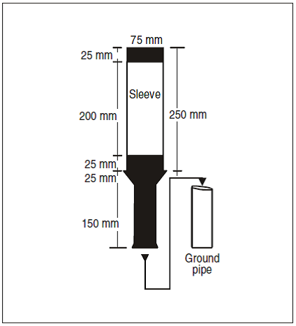
Figure GM-P-1. Taxiway edge marker
[Issue: ADR-DSN/3]
[Issue: ADR-DSN/4]
[Issue: ADR-DSN/6]
CS ADR-DSN.P.830 Taxiway centre line markers
ED Decision 2014/013/R
(a)Applicability:
(1)Taxiway centre line markers should be provided on a taxiway where taxiway centre line or edge lights or taxiway edge markers are not provided.
(2)Taxiway centre line markers should be provided on a taxiway where taxiway centre line lights are not provided if there is a need to improve the guidance provided by the taxiway centre line marking.
(b)Location
(1)Taxiway centre line markers should be installed at least at the same location as would taxiway centre line lights had they been used.
(2)Taxiway centre line markers should be located on the taxiway centre line marking except that they may be offset by not more than 0.3 m where it is not practicable to locate them on the marking.
(c)Characteristics:
(1)A taxiway centre line marker should be retroreflective green.
(2)The marked surface as viewed by the pilot should be a rectangle, and should have a minimum viewing area of 20 cm2.
(3)Taxiway centre line markers should be so designed and fitted as to withstand being run over by the wheels of an aircraft without damage either to the aircraft or to the markers themselves.
GM1 ADR-DSN.P.830 Taxiway centre line markers
ED Decision 2014/013/R
intentionally left blank
CS ADR-DSN.P.835 Unpaved taxiway edge markers
ED Decision 2014/013/R
(a)Applicability: Where the extent of an unpaved taxiway is not clearly indicated by its appearance compared with that of the surrounding ground, markers should be provided.
(b)Characteristics:
(1)Where taxiway lights are provided, the markers should be incorporated in the light fixtures.
(2)Where there are no lights, suitable markers should be placed so as to clearly delineate the taxiway.
GM1 ADR-DSN.P.835 Unpaved taxiway edge markers
ED Decision 2014/013/R
intentionally left blank
CHAPTER Q — VISUAL AIDS FOR DENOTING OBSTACLES
CS ADR-DSN.Q.840 Objects to be marked and/or lighted within the lateral boundaries of the obstacle limitation surfaces
ED Decision 2016/027/R
(a)Applicability: The specifications for objects to be marked and/or lighted within the lateral boundaries of the obstacle limitation surfaces apply only to the area under control of the aerodrome operator.
(b)Elevated aeronautical ground lights within the movement area should be marked so as to be conspicuous by day. Obstacle lights should not be installed on elevated ground lights or signs in the movement area.
(c)All obstacles within the distance specified in Table D-1, column (11), (12) or (13), from the centre line of a taxiway, an apron taxiway or aircraft stand taxilane should be marked and, if the taxiway, apron taxiway or aircraft stand taxilane is used at night, lighted.
(d)A fixed obstacle that extends above a take-off climb, approach or transitional surface within 3 000 m of the inner edge of the take-off climb or approach surface should be marked and if the runway is used at night, lighted, except that:
(1)such marking and lighting may be omitted when the obstacle is shielded by another fixed obstacle;
(2)the marking may be omitted when the obstacle is lighted by medium-intensity obstacle lights, Type A, by day, and its height above the level of the surrounding ground does not exceed 150 m;
(3)the marking may be omitted when the obstacle is lighted by high-intensity obstacle lights by day if medium intensity lights, Type A, are deemed insufficient; and
(4)the lighting may be omitted where the obstacle is a lighthouse and an safety assessment indicates the lighthouse light to be sufficient.
(e)A fixed object, other than an obstacle, adjacent to a take-off climb, approach or transitional surface should be marked and, if the runway is used at night, lighted, if such marking and lighting is considered necessary to ensure its avoidance, except that the marking may be omitted when:
(1)the object is lighted by medium-intensity obstacle lights, Type A, by day, and its height above the level of the surrounding ground does not exceed 150 m; or
(2)the object is lighted by high-intensity obstacle lights by day if medium intensity lights, Type A, are deemed insufficient.
(f)A fixed obstacle that extends above a horizontal surface should be marked and if the aerodrome is used at night, lighted, except that:
(1)such marking and lighting may be omitted when:
(i)the obstacle is shielded by another fixed obstacle; or
(ii)for a circuit extensively obstructed by immovable objects or terrain, procedures have been established to ensure safe vertical clearance below prescribed flight paths; or
(iii)an safety assessment shows the obstacle is not of operational significance.
(2)the marking may be omitted when the obstacle is lighted by medium-intensity obstacle lights, Type A, by day, and its height above the level of the surrounding ground does not exceed 150 m;
(3)the marking may be omitted when the obstacle is lighted by high-intensity obstacle lights by day if medium intensity lights, Type A, are deemed insufficient; and
(4)the lighting may be omitted where the obstacle is a lighthouse and a safety assessment indicates the lighthouse light to be sufficient.
(g)A fixed object that extends above an obstacle protection surface should be marked and, if the runway is used at night, lighted, except that such marking and lighting may be omitted when the obstacle is shielded by another fixed obstacle.
[Issue: ADR-DSN/3]
GM1 ADR-DSN.Q.840 Objects to be marked and/or lighted within the lateral boundaries of the obstacle limitation surfaces
ED Decision 2022/006/R
(a)The marking and/or lighting of obstacles is intended to reduce hazards to aircraft by indicating the presence of the obstacles. It does not necessarily reduce operating limitations which may be imposed by an obstacle.
(b)Other objects inside the obstacle limitation surfaces should be marked and/or lighted if a safety assessment indicates that the object could constitute a hazard to aircraft (this includes objects adjacent to visual routes e.g. waterway or highway).
(c)Overhead wires, cables, etc., crossing a river, waterway, valley or highway should be marked and their supporting towers marked and lighted if a safety assessment indicates that the wires or cables could constitute a hazard to aircraft.
(d)An autonomous aircraft detection system may be installed on or near an obstacle (or group of obstacles such as wind farms) within or outside the lateral boundaries of the obstacle limitation surfaces. This system is designed to operate the lighting only when it detects an aircraft approaching the obstacle, to reduce light exposure to local residents. Additional guidance on the design and installation of an autonomous aircraft detection system is available in the ICAO Doc 9157, Aerodrome Design Manual, Part 4, Visual Aids.
The inclusion of this guidance is not intended to imply that such a system has to be provided.
[Issue: ADR-DSN/3]
[Issue: ADR-DSN/6]
CS ADR-DSN.Q.841 Objects to be marked and/or lighted outside the lateral boundaries of the obstacle limitation surfaces
ED Decision 2016/027/R
(a)Applicability: The specifications for objects to be marked and/or lighted outside the lateral boundaries of the obstacle limitation surfaces apply only to the area under control of the aerodrome operator.
(b)Obstacles in accordance with CS ADR-DSN.J.487 should be marked and lighted, except that the marking may be omitted when the obstacle is lighted by high-intensity obstacle lights by day.
(c)When considered as an obstacle, other objects outside the obstacle limitation surfaces should be marked and/or lighted.
[Issue: ADR-DSN/3]
GM1 ADR-DSN.Q.841 Objects to be marked and/or lighted outside the lateral boundaries of the obstacle limitation surfaces
ED Decision 2016/027/R
(a)Other objects outside the obstacle limitation surfaces should be marked and/or lighted if a safety assessment indicates that the object could constitute a hazard to aircraft (this includes objects adjacent to visual routes e.g. waterway, highway).
(b)Overhead wires, cables, etc., crossing a river, waterway, valley or highway should be marked and their supporting towers marked and lighted if a safety assessment indicates that the wires or cables could constitute a hazard to aircraft.
[Issue: ADR-DSN/3]
CS ADR-DSN.Q.845 Marking of fixed objects
ED Decision 2022/006/R
(a)General: All fixed objects to be marked should, whenever practicable, be coloured but if this is not practicable, markers or flags should be displayed on or above them, except those objects that are sufficiently conspicuous by their shape, size, or colour need not be otherwise marked.
(b)Marking by colour
(1)An object should be coloured to show a chequered pattern if it has essentially unbroken surfaces, and its projection on any vertical plane equals or exceeds 4.5 m in both dimensions. The pattern should consist of rectangles of not less than 1.5 m and not more than 3 m on a side, the corners being of the darker colour. The colours of the pattern should contrast with each other and with the background against which they should be seen.
(2)An object should be coloured to show alternating contrasting bands if:
(i)it has essentially unbroken surfaces, and has one dimension, horizontal or vertical, greater than 1.5 m, and the other dimension, horizontal or vertical, less than 4.5 m; or
(ii)it is of skeletal type with either a vertical or a horizontal dimension greater than 1.5 m.
(3)The bands should be perpendicular to the longest dimension and have a width approximately 1/7 of the longest dimension or 30 m, whichever is less. The colours of the bands should contrast with the background against which they should be seen. Orange and white should be used, except where such colours are not conspicuous when viewed against the background. The bands on the extremities of the object should be of the darker colour (see Figures Q-1 and Q-2). The dimensions of the marking band widths are shown in Table Q-4.
(4)An object should be coloured in a single conspicuous colour if its projection on any vertical plane has both dimensions less than 1.5 m. Orange or red should be used, except where such colours merge with the background.
(c)Marking by flags
(1)Flags used to mark fixed objects should be displayed around, on top of, or around the highest edge of the object. When flags are used to mark extensive objects or groups of closely spaced objects, they should be displayed at least every 15 m. Flags should not increase the hazard presented by the object they mark.
(2)Flags used to mark fixed objects should not be less than 0.6 m on each side.
(3)Flags used to mark fixed objects should be orange in colour or a combination of two triangular sections, one orange and the other white, or one red and the other white. Except where such colours merge with the background, other conspicuous colours should be used.
(d)Marking by markers
(1)Markers displayed on or adjacent to objects should be located in conspicuous positions so as to retain the general definition of the object and should be recognisable in clear weather from a distance of at least 1 000 m for an object to be viewed from the air and 300 m for an object to be viewed from the ground in all directions in which an aircraft is likely to approach the object. The shape of markers should be distinctive to the extent necessary to ensure that they are not mistaken for markers employed to convey other information, and they should be such that the hazard presented by the object they mark is not increased.
(2)A marker should be of one colour. When more than one markers are installed, white and red, or white and orange markers should be displayed alternately. The colour selected should contrast with the background against which it should be seen.
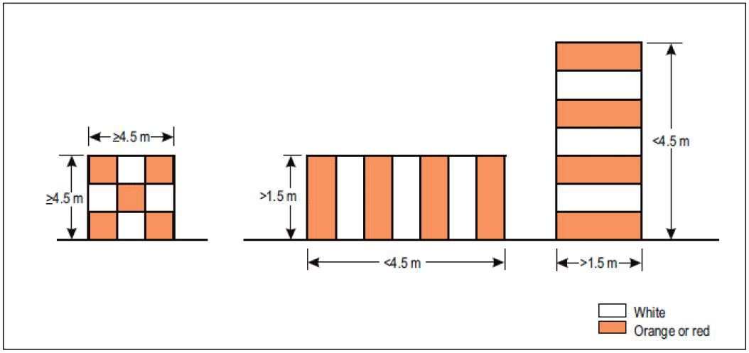
Figure Q-1. Basic marking patterns
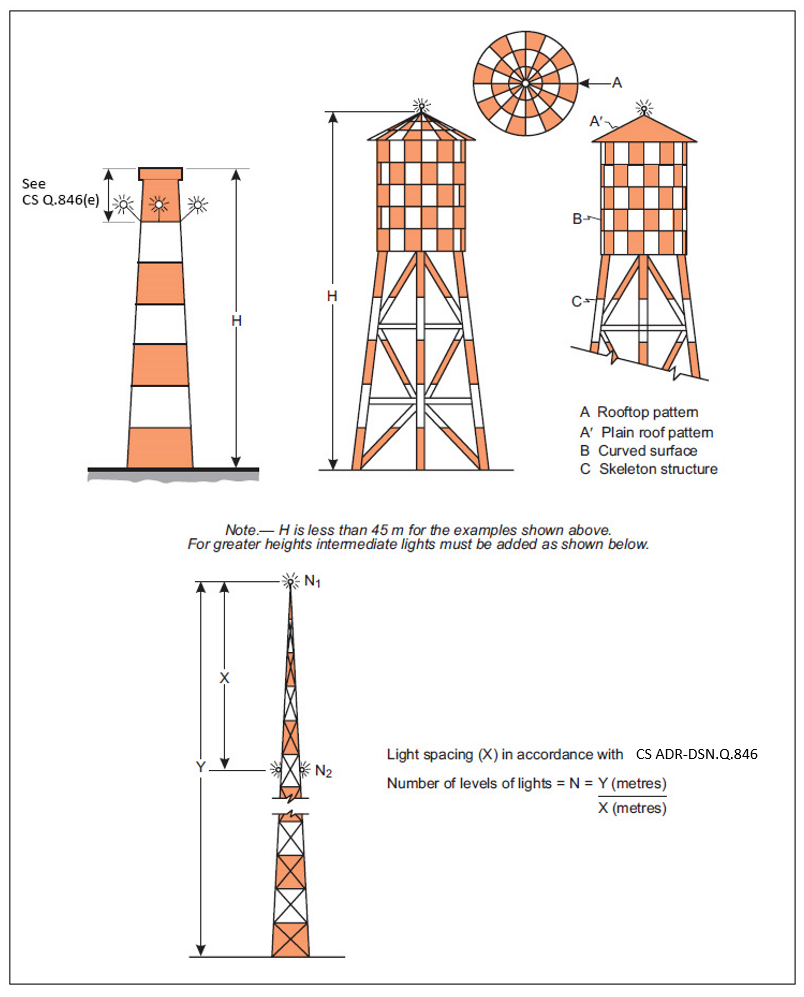
Figure Q-2. Examples of marking and lighting of tall structures
[Issue: ADR-DSN/3]
[Issue: ADR-DSN/6]
GM1 ADR-DSN.Q.845 Marking of fixed objects
ED Decision 2016/027/R
(a)Orange and white or alternatively red and white are preferably used, except where such colours merge with the background.
(b)Table Q-4 shows a formula for determining band widths, and for having an odd number of bands, thus permitting both the top and bottom bands to be of the darker colour.
(c)Against some backgrounds it may be found necessary to use a different colour from orange or red to obtain sufficient contrast.
(d)Alternative spacing may be suitable; priority is to highlight the location and definition of the object.
[Issue: ADR-DSN/3]
CS ADR-DSN.Q.846 Lighting of fixed objects
ED Decision 2017/021/R
(a)The presence of objects which should be lighted, as specified in CS ADR-DSN.Q.840 and CS ADR-DSN.Q.841 should be indicated by low-, medium- or high-intensity obstacle lights, or a combination of such lights.
(b)Low-intensity obstacle lights, Types A, B, C and D, medium-intensity obstacle lights, Types A, B and C and high-intensity obstacle lights Types A and B, should be in accordance with the specifications in Table Q-1, CS ADR-DSN.U.930 and Figure U-1A or U-1B, as appropriate..
(c)The number and arrangement of low-, medium- or high-intensity obstacle lights at each level to be marked should be such that the object is indicated from every angle in azimuth. Where a light is shielded in any direction by another part of the object or by an adjacent object, additional lights should be provided on that adjacent object, or the part of the object that is shielding the light, in such a way as to retain the general definition of the object to be lighted. If the shielded light does not contribute to the definition of the object to be lighted, it may be omitted.
(d)In case of an object to be lighted one or more low-, medium- or high-intensity obstacle lights should be located as close as practicable to the top of the object.
(e)In the case of chimney or other structure of like function, the top lights should be placed sufficiently below the top so as to minimise contamination by smoke, etc. (see Figure Q-2).
(f)In the case of a tower or antenna structure indicated by high-intensity obstacle lights by day with an appurtenance such as a rod or an antenna greater than 12 m where it is not practicable to locate a high-intensity obstacle light on the top of the appurtenance, such a light should be located at the highest practicable point, and, if practicable, a medium-intensity obstacle light, Type A, mounted on the top.
(g)In the case of an extensive object or of a group of closely spaced objects to be lighted that are:
(1)Penetrating a horizontal obstacle limitation surface (OLS) or located outside an OLS, the top lights should be so arranged as to at least indicate the points or edges of the object highest in relation to OLS or above the ground, and so as to indicate the general definition and the extent of the objects; and
(2)Penetrating a sloping OLS, the top lights should be so arranged as to at least indicate the points or edges of the object highest in relation to the OLS, and so as to indicate the general definition and the extent of the objects. If two or more edges are of the same height, the edge nearest the landing area should be marked.
(h)When the obstacle limitation surface concerned is sloping and the highest point above the obstacle limitation surface is not the highest point of the object, additional obstacle lights should be placed on the highest point of the object.
(i)Where lights are applied to display the general definition of an extensive object or a group of closely spaced objects, and
(1)Low-intensity lights are used, they should be spaced at longitudinal intervals not exceeding 45 m.
(2)Medium-intensity lights are used, they should be spaced at longitudinal intervals not exceeding 900 m.
(j)High-intensity obstacle lights, Type A, and medium-intensity obstacle lights, Types A and B, located on an object should flash simultaneously.
(k)The installation setting angles for high-intensity obstacle lights, Type A, should be in accordance with Table Q-5.
[Issue: ADR-DSN/3]
[Issue: ADR-DSN/4]
GM1 ADR-DSN.Q.846 Lighting of fixed objects
ED Decision 2016/027/R
(a)Guidance on how a combination of low-, medium-, and/or high-intensity lights on obstacles should be displayed is given in Figures GM-Q-1 to GM-Q-8.
(b)High-intensity obstacle lights are intended for day use as well as night use. Care should be taken to ensure that these lights do not create disconcerting dazzle or environmental concerns. Guidance on the design, location, and operation of high-intensity obstacle lights is given in ICAO Doc 9157, Aerodrome Design Manual, Part 4, Visual Aids.
(c)Where, the use of high-intensity obstacle lights, Type A, or medium-intensity obstacle lights, Type A, at night may dazzle pilots in the vicinity of an aerodrome (within approximately 10 000 m radius) or cause significant environmental concerns, a dual obstacle lighting system should be provided. This system should be composed of high-intensity obstacle lights, Type A, or medium intensity obstacle lights, Type A, as appropriate, for daytime and twilight use and medium-intensity obstacle light, Type B or C, for night-time use.
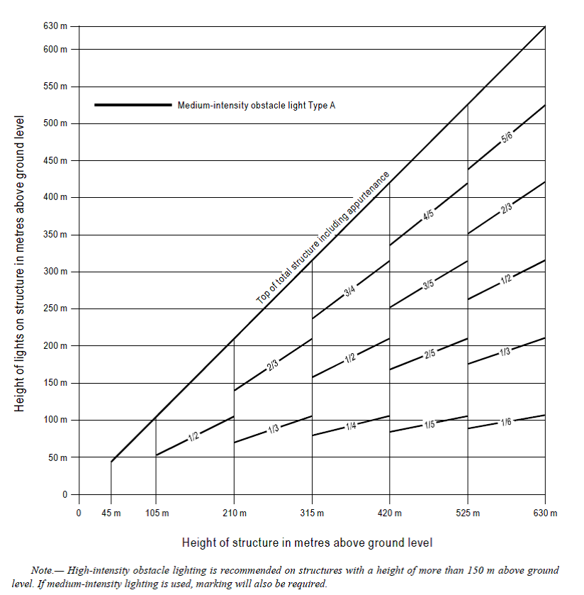
Figure GM-Q-1.Medium-intensity flashing-white obstacle lighting system, Type A
Figure GM-Q-2. Medium-intensity flashing-red obstacle lighting system, Type B
Figure GM-Q-3. Medium-intensity fixed-red obstacle lighting system, Type C
Figure GM-Q-4. Medium-intensity dual obstacle lighting system, Type A/Type B
Figure GM-Q-5. Medium-intensity dual obstacle lighting system, Type A/Type C
Figure GM-Q-6. High-intensity flashing-white obstacle lighting system, Type A
Figure GM-Q-7. High-/medium-intensity dual obstacle lighting system, Type A/Type B
Figure GM-Q-8. High-/medium-intensity dual obstacle lighting system, Type A/Type C
In the cases as stated in CS ADR-DSN.Q.848(c) and (d), normally the spacing would not exceed 52 m.
[Issue: ADR-DSN/3]
CS ADR-DSN.Q.847 Lighting of fixed objects with a height less than 45 m above ground level
ED Decision 2016/027/R
(a)Low-intensity obstacle lights, Type A or B, should be used where the object is a less extensive one and its height above the surrounding ground is less than 45 m.
(b)Where the use of low-intensity obstacle lights, Type A or B, would be inadequate, or an early special warning is required, then medium- or high-intensity obstacle lights should be used.
(c)Low-intensity obstacle lights, Type B, should be used either alone or in combination with medium-intensity obstacle lights, Type B, in accordance with subparagraph (d), below.
(d)Medium-intensity obstacle lights, Type A, B, or C, should be used where the object is an extensive one. Medium-intensity obstacle lights, Types A and C, should be used alone, whereas medium-intensity obstacle lights, Type B, should be used either alone or in combination with low-intensity obstacle lights, Type B.
[Issue: ADR-DSN/3]
GM1 ADR-DSN.Q.847 Lighting of fixed objects with a height less than 45 m above ground level
ED Decision 2016/027/R
A group of buildings is regarded as an extensive object.
[Issue: ADR-DSN/3]
CS ADR-DSN.Q.848 Lighting of fixed objects with a height 45 m to a height less than 150 m above ground level
ED Decision 2016/027/R
(a)Medium-intensity obstacle lights, Type A, B, or C, should be used where the object is an extensive one. Medium-intensity obstacle lights, Types A and C, should be used alone, whereas medium-intensity obstacle lights, Type B, should be used either alone or in combination with low-intensity obstacle lights, Type B.
(b)Where an object is indicated by medium-intensity obstacle lights, Type A, and the top of the object is more than 105 m above the level of the surrounding ground, or the elevation of tops of nearby buildings (when the object to be marked is surrounded by buildings), additional lights should be provided at intermediate levels. These additional intermediate lights should be spaced, as equally as practicable, between the top lights and ground level or the level of tops of nearby buildings as appropriate, with the spacing not exceeding 105 m.
(c)Where an object is indicated by medium-intensity obstacle lights, Type B, and the top of the object is more than 45 m above the level of the surrounding ground or the elevation of tops of nearby buildings (when the object to be marked is surrounded by buildings), additional lights should be provided at intermediate levels. These additional intermediate lights should be alternately low-intensity obstacle lights, Type B, and medium-intensity obstacle lights, Type B, and should be spaced as equally as practicable, between the top lights and ground level or the level of tops of nearby buildings as appropriate, with the spacing not exceeding 52 m.
(d)Where an object is indicated by medium-intensity obstacle lights, Type C, and the top of the object is more than 45 m above the level of the surrounding ground or the elevation of tops of nearby buildings (when the object to be marked is surrounded by buildings), additional lights should be provided at intermediate levels. These additional intermediate lights should be spaced as equally as practicable, between the top lights and ground level or the level of tops of nearby buildings, as appropriate, with the spacing not exceeding 52 m.
(e)Where high-intensity obstacle lights, Type A, are used, they should be spaced at uniform intervals not exceeding 105 m between the ground level and the top light(s) specified in paragraph CS ADR-DSN.Q.846(d), except that where an object to be marked is surrounded by buildings, the elevation of the tops of the buildings may be used as the equivalent of the ground level when determining the number of light levels.
[Issue: ADR-DSN/3]
GM1 ADR-DSN.Q.848 Lighting of fixed objects with a height 45 m to a height less than 150 m above ground level
ED Decision 2016/027/R
Low-intensity obstacle lights, Type A or B, may be used for obstacles higher than 45 m if it is determined to be sufficient.
[Issue: ADR-DSN/3]
CS ADR-DSN.Q.849 Lighting of fixed objects with a height 150 m or more above ground level
ED Decision 2016/027/R
(a)High-intensity obstacle lights, Type A, should be used to indicate the presence of an object if its height above the level of the surrounding ground exceeds 150 m and a safety assessment indicates such lights to be essential for the recognition of the object by day.
(b)Where high-intensity obstacle lights, Type A, are used, they should be spaced at uniform intervals not exceeding 105 m between the ground level and the top light(s) specified in CS ADR-DSN.Q.846(d), except where an object to be marked is surrounded by buildings, the elevation of the tops of the buildings may be used as the equivalent of the ground level when determining the number of light levels.
(c)Where an object is indicated by medium-intensity obstacle lights, Type A, additional lights should be provided at intermediate levels. These additional intermediate lights should be spaced, as equally as practicable, between the top lights and ground level or the level of tops of nearby buildings, as appropriate, with the spacing not exceeding 105 m.
(d)Where an object is indicated by medium-intensity obstacle lights, Type B, additional lights should be provided at intermediate levels. These additional intermediate lights should be alternately low-intensity obstacle lights, Type B, and medium-intensity obstacle lights, Type B, and should be spaced, as equally as practicable, between the top lights and ground level or the level of tops of nearby buildings, as appropriate, with the spacing not exceeding 52 m.
(e)Where an object is indicated by medium-intensity obstacle lights, Type C, additional lights should be provided at intermediate levels. These additional intermediate lights should be spaced, as equally as practicable, between the top lights and ground level or the level of tops of nearby buildings, as appropriate, with the spacing not exceeding 52 m.
[Issue: ADR-DSN/3]
GM1 ADR-DSN.Q.849 Lighting of fixed objects with a height 150 m or more above ground level
ED Decision 2016/027/R
Where, the use of high-intensity obstacle lights, Type A, at night may dazzle pilots in the vicinity of an aerodrome (within approximately 10 000 m radius) or cause significant environmental concerns, medium-intensity obstacle lights, Type C, should be used alone, whereas medium-intensity obstacle lights, Type B, should be used either alone or in combination with low-intensity obstacle lights, Type B.
[Issue: ADR-DSN/3]
CS ADR-DSN.Q.850
ED Decision 2021/004/R
Intentionally left blank
[Issue: ADR-DSN/3]
[Issue: ADR-DSN/5]
GM1 ADR-DSN.Q.850
ED Decision 2021/004/R
Intentionally left blank
[Issue: ADR-DSN/3]
[Issue: ADR-DSN/5]
CS ADR-DSN.Q.851 Marking and lighting of wind turbines
ED Decision 2016/027/R
(a)Applicability: When considered as an obstacle a wind turbine should be marked and/or lighted.
(b)Marking: The rotor blades, nacelle and upper 2/3 of the supporting mast of wind turbines should be painted white, or if after a safety assessment, it is determined that other colour will improve safety.
(c)Lighting:
(1)Where lighting is deemed necessary for a single wind turbine or short line of wind turbines, the installation should be in accordance with paragraph (c)(2)(v) below, or as determined by a safety assessment.
(2)When lighting is deemed necessary in the case of a wind farm (i.e. a group of two or more wind turbines), the wind farm should be regarded as an extensive object and lights should be installed:
(i)to identify the perimeter of the wind farm;
(ii)respecting the maximum spacing, in accordance with CS ADR-DSN.Q.846(i), between the lights along the perimeter, or if after a safety assessment, it is determined that a greater spacing can be used;
(iii)so that, where flashing lights are used, they flash simultaneously throughout the wind farm;
(iv)so that, within a wind farm, any wind turbines of significantly higher elevation are also identified wherever they are located; and
(v)at locations prescribed in (i), (ii) and (iv):
(A)for wind turbines of less than 150 m in overall height (hub height plus vertical blade height), medium intensity lighting on the nacelle;
(B)for wind turbines from 150 m to 315 m in overall height, in addition to the medium intensity light installed on the nacelle, a second light serving as an alternate should be provided in case of failure of the operating light; the lights should be installed to assure that the output of either light is not blocked by the other;
(C)in addition, for wind turbines from 150 m to 315 m in overall height, an intermediate level at half the nacelle height of at least three low intensity Type E lights, as specified in CS ADR-DSN.Q.846(c), that are configured to flash at the same rate as the light on the nacelle; low-intensity Type A or B lights may be used if an safety assessment shows that low intensity Type E lights are not suitable.
(3)The obstacle lights should be installed on the nacelle in such a manner as to provide an unobstructed view for aircraft approaching from any direction.
[Issue: ADR-DSN/3]
GM1 ADR-DSN.Q.851 Marking and lighting of wind turbines
ED Decision 2016/027/R
(a)Additional markings and lighting may be provided to the wind turbines if indicated by a safety assessment.
(b)Case by case studies for wind turbines of more than 315 m of overall height may conclude that additional markings and lighting are required.
[Issue: ADR-DSN/3]
CS ADR-DSN.Q.852 Marking and lighting of overhead wires, cables, supporting towers, etc.
ED Decision 2025/004/R
(a)Marking: The wires, cables, etc. to be marked should be equipped with markers; the supporting tower should be coloured.
(b)Marking by colours: The supporting towers of overhead wires, cables, etc. that require marking should be marked in accordance with CS ADR-DSN.Q.845(b), except that the marking of the supporting towers may be omitted when they are lighted by high-intensity obstacle lights by day.
(c)Marking by markers:
(1)Markers displayed on or adjacent to objects should be located in conspicuous positions so as to retain the general definition of the object and should be recognisable in clear weather from a distance of at least 1 000 m for an object to be viewed from the air and 300 m for an object to be viewed from the ground in all directions in which an aircraft is likely to approach the object. The shape of markers should be distinctive to the extent necessary to ensure that they are not mistaken for markers employed to convey other information, and they should be such that the hazard presented by the object they mark is not increased.
(2)A marker displayed on an overhead wire, cable, etc., should be spherical and have a diameter of not less than 60 cm.
(3)The spacing between two consecutive markers, or between a marker and a supporting tower, should be appropriate to the diameter of the marker. The spacing should normally not exceed:
(i)30 m where the marker diameter is 60 cm, increasing progressively with increase of the marker diameter to:
(ii)35 m where the marker diameter is 80 cm; and
(iii)further progressive increases to a maximum of 40 m where the marker diameter is of at least 130 cm.
Where multiple wires, cables, etc., are involved, a marker should be located not lower than the level of the highest wire at the point marked.
(4)A marker should be of one colour. When installed, white and red, or white and orange, markers should be displayed alternately. The colour selected should contrast with the background against which it should be seen.
(5)When it has been determined that an overhead wire, cable, etc., needs to be marked but it is not practicable to install markers on the wire, cable, etc., then high-intensity obstacle lights, Type B, should be provided on their supporting towers.
(d)Lighting:
(1)High-intensity obstacle lights, Type B, should be used to indicate the presence of the tower supporting overhead wires, cables, etc. where:
(i)a safety assessment indicates such light to be essential for the recognition of the presence of wires, cables, etc.; or
(ii)it has not been found practicable to install marker on the wires, cables, etc.
(2)Where high-intensity obstacle lights, Type B, are used, they should be located at three levels:
(i)at the top of the tower;
(ii)at the lowest level of the catenary of the wires or cables; and
(iii)at approximately midway between these two levels.
(3)High-intensity obstacle lights, Type B, indicating the presence of a tower supporting overhead wires, cables, etc., should flash sequentially; first the middle light, second the top light, and last the bottom light. The intervals between flashes of the lights should approximate the following ratios:
Flash interval between | Ratio of cycle time |
Middle and top light | 1/13 |
Top and bottom light | 2/13 |
Bottom and middle light | 10/13 |
(4)The installation setting angles for high-intensity obstacle lights, Types B, should be in accordance with Table Q-5.
(1) | (2) | (3) | (4) | (5) | (6) | (7) |
Light type | Colour | Signal type/ (Flash Rate) | Peak intensity (cd) at given Background Luminance (b) | Light Distribution Table | ||
Day (Above 500 cd/m2) | Twilight (50-500 cd/m2) | Night (Below 50 cd/m2) | ||||
Low-intensity Type A (fixed obstacle) | Red | Fixed | N/A | N/A | 10 | Table Q-2 |
Low-intensity Type B (fixed obstacle) | Red | Fixed | N/A | N/A | 32 | Table Q-2 |
Low-intensity Type C (mobile obstacle) | Yellow/ Blue (a) | Flashing (60-90 fpm) | N/A | 40 | 40 | Table Q-2 |
Low-intensity Type D (follow-me vehicle) | Yellow | Flashing (60-90 fpm) | N/A | 200 | 200 | Table Q-2 |
Low-intensity, Type E | Red | Flashing (c) | N/A | N/A | 32 | Table Q-2 (Type B) |
Medium-intensity Type A | White | Flashing (20-60 fpm) | 20 000 | 20 000 | 2 000 | Table Q-3 |
Medium-intensity Type B | Red | Flashing (20-60 fpm) | N/A | N/A | 2 000 | Table Q-3 |
Medium-intensity Type C | Red | Fixed | N/A | N/A | 2 000 | Table Q-3 |
High-intensity Type A | White | Flashing (40-60 fpm) | 200 000 | 20 000 | 2 000 | Table Q-3 |
High-intensity Type B | White | Flashing (40-60 fpm) | 100 000 | 20 000 | 2 000 | Table Q-3 |
(a)ADR.OPS.B.080(a)(2), AMC1 ADR.OPS.B.080(a) and AMC2 ADR.OPS.B.080(a) (b)For flashing lights, effective intensity as determined in accordance with ICAO Doc 9157, Aerodrome Design Manual, Part 4, Visual Aids. (c)For wind turbine application, to flash at the same rate as the lighting on the nacelle. | ||||||
Table Q-1. Characteristics of obstacle lights
Minimum intensity (a) | Maximum intensity (a) | Vertical beam spread (f) | ||
Minimum beam spread | Intensity | |||
Type A | 10 cd (b) | N/A | 10° | 5 cd |
Type B | 32 cd (b) | N/A | 10° | 16 cd |
Type C | 40 cd (b) | 400 cd | 12(d) | 20 cd |
Type D | 200 cd (c) | 400 cd | N/A(e) | N/A |
Note: This table does not include recommended horizontal beam spreads. CS ADR-DSN.Q.846(c) requires 360° coverage around an obstacle. Therefore, the number of lights needed to meet this requirement will depend on the horizontal beam spreads of each light as well as the shape of the obstacle. Thus, with narrower beam spreads, more lights will be required. (a)360° horizontal. For flashing lights, the intensity is read into effective intensity, as determined in accordance with ICAO, Aerodrome Design Manual, Part 4, Visual Aids. (b)Between 2 and 10° vertical. Elevation vertical angles are referenced to the horizontal when the light is levelled. (c)Between 2 and 20° vertical. Elevation vertical angles are referenced to the horizontal when the light is levelled. (d)Peak intensity should be located at approximately 2.5° vertical. (e)Peak intensity should be located at approximately 17° vertical. (f)Beam spread is defined as the angle between the horizontal plan and the directions for which the intensity exceeds that mentioned in the ‘intensity’ column. | ||||
Table Q-2. Light distribution for low-intensity obstacle lights
Benchmark intensity | Minimum requirements | Recommendations | |||||||||
Vertical elevation angle (b) | Vertical beam spread (c) | Vertical elevation angle (b) | Vertical beam spread (c) | ||||||||
0° | -1° | 0° | -1° | -10° | |||||||
Minimum average intensity (a) | Minimum intensity (a) | Minimum intensity (a) | Minimum beam spread | Intensity (a) | Maximum intensity (a) | Maximum intensity (a) | Maximum intensity (a) | Maximum beam spread | Intensity (a) | ||
200 000 | 200 000 | 150 000 | 75 000 | 3° | 75 000 | 250 000 | 112 500 | 7 500 | 7° | 75 000 | |
100 000 | 100 000 | 75 000 | 37 500 | 3° | 37 500 | 125 000 | 56 250 | 3 750 | 7° | 37 500 | |
20 000 | 20 000 | 15 000 | 7 500 | 3° | 7 500 | 25 000 | 11 250 | 750 | N/A | N/A | |
2 000 | 2 000 | 1 500 | 750 | 3° | 750 | 2 500 | 1 125 | 75 | N/A | N/A | |
Note: This table does not include recommended horizontal beam spreads. CS ADR-DSN.Q.846(c) requires 360° coverage around an obstacle. Therefore, the number of lights needed to meet this requirement will depend on the horizontal beam spreads of each light as well as the shape of the obstacle. Thus, with narrower beam spreads, more lights will be required. (a)360° horizontal. All intensities are expressed in Candela. For flashing lights, the intensity is read into effective intensity, as determined in accordance with ICAO Doc 9157, Aerodrome Design Manual, Part 4, Visual Aids. (b)Elevation vertical angles are referenced to the horizontal when the light unit is levelled. (c)Beam spread is defined as the angle between the horizontal plan and the directions for which the intensity exceeds that mentioned in the ‘intensity’ column. Note: an extended beam spread may be necessary under specific configuration and justified by a safety assessment. | |||||||||||
Table Q-3. Light distribution for medium- and high-intensity obstacle lights according to benchmark intensities of Table Q-1
Longest dimension | Band width | |
Greater than | Not exceeding | |
1.5 m | 210 m | 1/7 of longest dimension |
210 m | 270 m | 1/9 “ “ “ |
270 m | 330 m | 1/11 “ “ “ |
330 m | 390 m | 1/13 “ “ “ |
390 m | 450 m | 1/15 “ “ “ |
450 m | 510 m | 1/17 “ “ “ |
510 m | 570 m | 1/19 “ “ “ |
570 m | 630 m | 1/21 “ “ “ |
Table Q-4. Marking band widths
Height of light unit above terrain (AGL) | Angle of the peak of the beam above the horizontal | |
Greater than | Not exceeding | |
151 m | 0° | |
122 m | 151 m | 1° |
92 m | 122 m | 2° |
92 m | 3° | |
Table Q-5. Installation setting angles for high-intensity obstacle lights
[Issue: ADR-DSN/3]
[Issue: ADR-DSN/4]
[Issue: ADR-DSN/6]
[Issue: ADR-DSN/7]
GM1 ADR-DSN.Q.852 Marking and lighting of overhead wires, cables, supporting towers, etc.
ED Decision 2016/027/R
(a)Where high-intensity obstacle lights, Type B, are used, and it is not possible to locate them as described in CS ADR-DSN.Q.852(d)(2), in some cases, this may require locating the lights off the tower.
(b)High-intensity obstacle lights are intended for day use as well as night use. Care should be taken to ensure that these lights do not create disconcerting dazzle or environmental concerns. Guidance on the design, location, and operation of high-intensity obstacle lights is given in ICAO Doc 9157, Aerodrome Design Manual, Part 4, Visual Aids.
(c)Where the use of high-intensity obstacle lights, Type B, at night may dazzle pilots in the vicinity of an aerodrome (within approximately 10 000 m radius) or cause significant environmental concerns, a dual obstacle lighting system should be provided. This system should be composed of high-intensity obstacle lights, Type B, for daytime and twilight use and medium-intensity obstacle lights, Type B, for night-time use. Where medium-intensity lights are used they should be installed at the same level as the high-intensity obstacle light Type B.
[Issue: ADR-DSN/3]
CHAPTER R — VISUAL AIDS FOR DENOTING RESTRICTED USE AREAS
CS ADR-DSN.R.855 Closed runways and taxiways, or parts thereof
ED Decision 2025/004/R
Characteristics of closed markings: The closed marking should be of the form and proportions as detailed in Figure R-1, Illustration (a), when displayed on a runway, and should be of the form and proportions as detailed in Figure R-1, Illustration (b), when displayed on a taxiway. The marking should be white when displayed on a runway and should be yellow when displayed on a taxiway.
Figure R-1. Runway and taxiway closed markings
[Issue: ADR-DSN/3]
[Issue: ADR-DSN/5]
[Issue: ADR-DSN/7]
GM1 ADR-DSN.R.855 Closed runways and taxiways, or parts thereof
ED Decision 2021/004/R
Information regarding the physical removal of runway and taxiway markings is contained in AMC1 ADR.OPS.C.015(d) and GM1 ADR.OPS.C.015(d).
[Issue: ADR-DSN/5]
CS ADR-DSN.R.860 Non-load-bearing surfaces
ED Decision 2016/027/R
(a)Shoulders for taxiways, runway turn pads, holding bays and aprons, and other non-load-bearing surfaces which cannot readily be distinguished from load-bearing surfaces and which, if used by aircraft, might result in damage to the aircraft, should have the boundary between such areas and the load-bearing surface marked by a taxi side stripe marking.
(b)A taxi side stripe marking should consist of a pair of solid lines, each 15 cm wide and spaced 15 cm apart, and the same colour as the taxiway centre line marking.
[Issue: ADR-DSN/3]
GM1 ADR-DSN.R.860 Non-load-bearing surfaces
ED Decision 2016/027/R
(a)A taxi side stripe marking could also be placed along the edge of the load-bearing pavement to emphasise the location of the taxiway edge, with the outer edge of the marking approximately on the edge of the load-bearing pavement.
(b)At intersections of taxiways and on other areas where, due to turning, the possibility for confusion between the side stripe markings and centre line markings may exist, or where the pilot may not be sure on which side of the edge marking the non-load bearing pavement is, the additional provision of transverse stripes on the non-load bearing surface has been found to be of assistance.
(c)As shown in Figure GM-R-1, the transverse stripes should be placed perpendicular to the side stripe marking.
(d)On curves, a stripe should be placed at each point of tangency of the curve and at intermediate points along the curve so that the interval between stripes does not exceed 15 m. If deemed desirable to place transverse stripes on small straight sections, the spacing should not exceed 30 m.
(e)The width of the marks should be 0.9 m, and they should extend to within 1.5 m of the outside edge of the stabilised paving or be 7.5 m long whichever is shorter. The colour of the transverse stripes should be the same as that of the edge stripes, i.e. yellow.
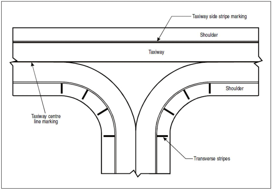
Figure GM-R-1. Marking of non-load bearing paved taxiway surface
More guidance on providing additional transverse stripes at an intersection or a small area on the apron is given in ICAO Doc 9157, Aerodrome Design Manual, Part 4, Visual Aids.
[Issue: ADR-DSN/3]
CS ADR-DSN.R.865 Pre-threshold area
ED Decision 2014/013/R
(a)Applicability of Pre-threshold area: When the surface before a threshold is paved and exceeds 60 m in length, and is not suitable for normal use by aircraft, the entire length before the threshold should be marked with a chevron marking.
(b)Location: A chevron marking should point in the direction of the runway and be placed as shown in Figure R-2.
(c)Characteristics: A chevron marking should be of conspicuous colour and contrast with the colour used for the runway markings; it should preferably be yellow and should have an overall width of at least 0.9 m.
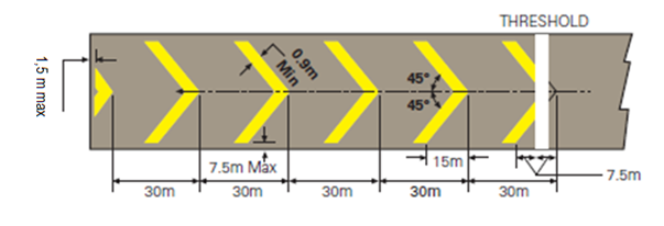
Figure R-2. Pre-threshold area marking
GM1 ADR-DSN.R.865 Pre-threshold area
ED Decision 2014/013/R
For pre-threshold areas shorter than 60 m, markings may be modified or reduced in size so as to present the correct picture to aircrew.
CS ADR-DSN.R.870 Unserviceable areas
ED Decision 2025/004/R
(a)Characteristics:
(1)Unserviceability markers should consist of conspicuous upstanding devices such as flags, cones, or marker boards.
(2)An unserviceability light should consist of a red fixed light. The light should have intensity sufficient to ensure conspicuity considering the intensity of the adjacent lights and the general level of illumination against which it would normally be viewed. In no case should the intensity be less than 10 cd of red light.
(3)An unserviceability cone should be at least 0.5 m in height and red, orange, or yellow, or any one of these colours in combination with white.
(4)An unserviceability flag should be at least 0.5 m square and red, orange, or yellow, or any one of these colours in combination with white.
(5)An unserviceability marker board should be at least 0.5 m in height and 0.9 m in length, with alternate red and white, or orange and white vertical stripes.
[Issue: ADR-DSN/7]
GM1 ADR-DSN.R.870 Unserviceable areas
ED Decision 2025/004/R
Unserviceable area lights are frangible. Their height is sufficiently low to preserve clearance for propellers and for engine pods of jet aircraft.
[Issue: ADR-DSN/7]
CHAPTER S — ELECTRICAL SYSTEMS
CS ADR-DSN.S.875 Electrical power supply systems for air navigation facilities
ED Decision 2014/013/R
(a)Adequate primary power supply should be available at aerodromes for the safe functioning of air navigation facilities.
(b)The design and provision of electrical power systems for aerodrome visual and radio navigation aids should be such that an equipment failure should not leave the pilot with inadequate visual and non-visual guidance, or misleading information.
(c)Electric power supply connections to those facilities for which secondary power is required should be so arranged that the facilities are automatically connected to the secondary power supply on failure of the primary source of power.
(d)The time interval between failure of the primary source of power and the complete restoration of the services required by CS ADR-DSN.S.880(d) should be as short as practicable, except that for visual aids associated with non-precision, precision approach, or take-off runways the requirements of Table S-1 for maximum switch-over times should apply.
GM1 ADR-DSN.S.875 Electrical power supply systems for air navigation facilities
ED Decision 2016/027/R
(a)The safety of operations at aerodromes depends on the quality of the supplied power. The total electrical power supply system may include connections to one or more external sources of electric power supply, one or more local generating facilities, and to a distribution network including transformers and switchgear. Many other aerodrome facilities supplied from the same system need to be taken into account while planning the electrical power system at aerodromes.
(b)The design and installation of the electrical systems need to take into consideration factors that can lead to malfunction, such as electromagnetic disturbances, line losses, power quality, etc. Additional guidance is given in ICAO Doc 9157, Aerodrome Design Manual, Part 5, Electrical Systems.
(c)Switch-over time is the time required for the actual intensity of a light measured in a given direction to fall from 50 % and recover to 50 % during a power supply changeover, when the light is being operated at intensities of 25 % or above.
(d)As a good practice, a measurement of the photometric parameters may be used for the evaluation of the switch-over time.
(1)If the switch-over time is greater than 1 second, the following corrective actions may be used to decrease the switch-over time:
(i)use of enhanced constant current regulators (CCR); or
(ii)use of uninterruptible power supply (UPS).
(2)If the photometric based switch-over time is below or equal 1 second, it is recommended to analyse the electrical system in order to find out an equivalent electrical switch-over time.
(e)For periodic measurement of the switch-over time a measurement of the equivalent electrical switch-over time at the feeding point of an aeronautical ground lights (AGL) system may be established.
[Issue: ADR-DSN/3]
CS ADR-DSN.S.880 Electrical power supply systems
ED Decision 2021/004/R
(a)For a precision approach runway, a secondary power supply capable of meeting the requirements of Table S-1 for the appropriate category of precision approach runway should be provided. Electric power supply connections to those facilities for which secondary power is required should be so arranged that the facilities are automatically connected to the secondary power supply on failure of the primary source of power.
(b)For a runway meant for take-off in runway visual range conditions less than a value of 800 m, a secondary power supply capable of meeting the relevant requirements of Table S-1 should be provided.
(c)At an aerodrome where the primary runway is a non-precision approach runway, a secondary power supply capable of meeting the requirements of Table S-1 should be provided except that a secondary power supply for visual aids need not be provided for more than one non-precision approach runway.
(d)The following aerodrome facilities should be provided with a secondary power supply capable of supplying power when there is a failure of the primary power supply:
(1)the signalling lamp and the minimum lighting necessary to enable air traffic services personnel to carry out their duties;
(2)obstacle lights which are essential to ensure the safe operation of aircraft;
(3)approach, runway and taxiway lighting as specified in CS ADR-DSN.M.625 to CS ADRDSN.M.745;
(4)meteorological equipment;
(5)essential equipment and facilities for the parking position if provided, in accordance with CS ADR-DSN.M.750(a) and CS ADR-DSN.M.755(a); and
(6)illumination of apron areas over which passengers may walk.
Runway | Lighting aids requiring power | Maximum switch-over time |
Non-instrument | Visual approach slope indicatorsa Runway edgeb Runway thresholdb Runway endb Obstaclea Stopway end Stopway edge | See |
Non-precision approach | Approach lighting system Visual approach slope indicatorsa, d Runway edged Runway thresholdd Runway endd Obstaclea Stopway end Stopway edge | 15 seconds 15 seconds 15 seconds 15 seconds 15 seconds 15 seconds 15 seconds 15 seconds |
Precision approach Category I | Approach lighting system Runway edged Visual approach slope indicatorsa, d Runway thresholdd Runway end Essential taxiwaya Obstaclea Stopway end Stopway edge | 15 seconds 15 seconds 15 seconds 15 seconds 15 seconds 15 seconds 15 seconds 15 seconds 15 seconds |
Precision approach Category II/III | Inner 300 m of the approach lighting system Other parts of the approach lighting system Obstaclea Runway edge Runway threshold Runway end Runway centre line Runway touchdown zone Runway guard lights All stop bars Essential taxiway Stopway end Stopway edge | 1 second 15 seconds 15 seconds 15 seconds 1 second 1 second 1 second 1 second 15 seconds 1 second 15 seconds 1 second 15 seconds |
Runway meant for take-off in runway visual range conditions less than a value of 800 m | Runway edge Runway end Runway centre line All stop bars Essential taxiwaya Obstaclea Stopway end Stopway edge | 15 secondsc 1 second 1 second 1 second 15 seconds 15 seconds 1 second 15 seconds |
a.Supplied with secondary power when their operation is essential to the safety of flight operation. b.The use of emergency lighting should be in accordance with any procedures established. c.One second where no runway centre line lights are provided. d.One second where approaches are over hazardous or precipitous terrain. | ||
Table S-1. Secondary power supply requirements (see CS ADR-DSN.S.875(d))
[Issue: ADR-DSN/3]
[Issue: ADR-DSN/4]
[Issue: ADR-DSN/5]
GM1 ADR-DSN.S.880 Electrical power supply
ED Decision 2016/027/R
(a)At an aerodrome where the primary runway is a non-instrument runway, a secondary power supply capable of meeting the requirements of CS ADR-DSN.S.875(d) should be provided, except that a secondary power supply for visual aids need not be provided when an emergency lighting system is provided and capable of being deployed in 15 minutes.
(b)Specifications for secondary power supply for radio navigation aids and ground elements of communications systems are given in ICAO Annex 10, Volume I, Aeronautical Telecommunications, Chapter 2.
(c)Requirements for a secondary power supply should be met by either of the following:
(1)independent public power which is a source of power supplying the aerodrome service from a substation other than the normal substation through a transmission line following a route different from the normal power supply route and such that the possibility of a simultaneous failure of the normal and independent public power supplies is extremely remote; or
(2)standby power unit(s) which are engine generators, batteries, etc. from which electric power can be obtained.
(d)Guidance on electrical systems is included in ICAO Doc 9157, Aerodrome Design Manual, Part 5, Electrical Systems.
(e)The requirement for minimum lighting may be met by other than electrical means.
[Issue: ADR-DSN/3]
CS ADR-DSN.S.885 System design
ED Decision 2014/013/R
(a)For a runway meant for use in runway visual range conditions less than a value of 550 m, the electrical systems for the power supply, lighting, and control of the lighting systems included in Table S-1 should be so designed that an equipment failure should not leave the pilot with inadequate visual guidance or misleading information.
(b)Where the secondary power supply of an aerodrome is provided by the use of duplicate feeders, such supplies should be physically and electrically separate so as to ensure the required level of availability and independence.
(c)Where a runway forming part of a standard taxi-route is provided with runway lighting and taxiway lighting, the lighting systems should be interlocked to preclude the possibility of simultaneous operation of both forms of lighting.
GM1 ADR-DSN.S.885 System design
ED Decision 2016/027/R
Guidance on means of providing this protection is given in ICAO Doc 9157, Aerodrome Design Manual, Part 5, Electrical Systems.
[Issue: ADR-DSN/3]
CS ADR-DSN.S.890 Monitoring
ED Decision 2021/004/R
(a)A system of monitoring should be employed to indicate the operational status of the lighting systems.
(b)Where lighting systems are used for aircraft control purposes, such systems should be monitored automatically so as to provide an indication of any fault which may affect the control functions. This information should be automatically relayed to the air traffic service unit.
(c)Where a change in the operational status of lights has occurred, an indication should be provided within two seconds for a stop bar at a runway-holding position and within five seconds for all other types of visual aids.
(d)For a runway meant for use in runway visual range conditions less than a value of 550 m, the lighting systems detailed in Table S-1 should be monitored automatically so as to provide an indication when the serviceability level of any element falls below a minimum serviceability level specified in ADR.OPS.C.015 (b)(1) to (b)(7). This information should be automatically relayed to the maintenance crew.
(e)For a runway meant for use in runway visual range conditions less than a value of 550 m, the lighting systems detailed in Table S-1 should be monitored automatically to provide an indication when the serviceability level of any element falls below a minimum level, below which operations should not continue. This information should be automatically relayed to the air traffic services unit and displayed in a prominent position.
[Issue: ADR-DSN/3]
[Issue: ADR-DSN/5]
GM1 ADR-DSN.S.890 Monitoring
ED Decision 2016/027/R
(a)For a runway meant for use in runway visual range conditions less than a value of 550 m, the minimum serviceability level of any element of the lighting system detailed in Table S-1, below which operations should not continue, is set up by the competent authority.
(b)Additional guidance on air traffic control interface and visual aids monitoring is given in ICAO Doc 9157, Aerodrome Design Manual, Part 5, Electrical Systems.
[Issue: ADR-DSN/3]
CS ADR-DSN.S.895
ED Decision 2021/004/R
Intentionally left bank
[Issue: ADR-DSN/3]
[Issue: ADR-DSN/5]
GM1 ADR-DSN.S.895
ED Decision 2021/004/R
Intentionally left bank
[Issue: ADR-DSN/3]
[Issue: ADR-DSN/5]
CHAPTER T — AERODROME OPERATIONAL SERVICES, EQUIPMENT AND INSTALLATION
CS ADR-DSN.T.900 Emergency access and service roads
ED Decision 2016/027/R
Emergency access roads and service roads should be equipped with a road-holding position, in accordance with CS ADR-DSN.L.600, CS ADR-DSN.M.770 and CS ADR-DSN.N.800, as appropriate, at all intersections with runway and taxiways.
[Issue: ADR-DSN/3]