
Filters
CS ADR-DSN.J.480 Precision approach runways
ED Decision 2017/021/R
(a)The following obstacle limitation surfaces should be established for a precision approach runway Category I:
(1)conical surface;
(2)inner horizontal surface;
(3)approach surface; and
(4)transitional surfaces.
(b)The following obstacle limitation surfaces should be established for a precision approach runway Category II or III:
(1)conical surface;
(2)inner horizontal surface;
(3)approach surface and inner approach surface;
(4)transitional surfaces and inner transitional surfaces; and
(5)balked landing surface.
(c)The heights and slopes of the surfaces should not be greater than, and their other dimensions not less than, those specified in Table J-1, except in the case of the horizontal section of the approach surface in paragraph (d) below.
(d)The approach surface should be horizontal beyond the point at which the 2.5 % slope intersects:
(1)a horizontal plane 150 m above the threshold elevation; or
(2)the horizontal plane passing through the top of any object that governs the obstacle clearance limit;
whichever is the higher.
(e)Fixed objects should not be permitted above the inner approach surface, the inner transitional surface or the balked landing surface, except for frangible objects which because of their function should be located on the strip. Mobile objects should not be permitted above these surfaces during the use of the runway for landing.
(f)New objects or extensions of existing objects should not be permitted above an approach surface or a transitional surface except when the new object or extension would be shielded by an existing immovable object.
(g)New objects or extensions of existing objects should not be permitted above the conical surface and the inner horizontal surface except when an object would be shielded by an existing immovable object, or if after a safety assessment, it is determined that the object would not adversely affect the safety or significantly affect the regularity of operations of aeroplanes.
(h)Existing objects above an approach surface, a transitional surface, the conical surface and inner horizontal surface should, as far as practicable, be removed except when an object would be shielded by an existing immovable object, or if after a safety assessment, it is determined that the object would not adversely affect the safety or significantly affect the regularity of operations of aeroplanes.
APPROACH RUNWAYS | ||||||||||
RUNWAY CLASSIFICATION | ||||||||||
Surface and dimensionsa | Non-instrument Code number | Non-precision approach Code number | Precision approach category | |||||||
I | II or III | |||||||||
1 | 2 | 3 | 4 | 1, 2 | 3 | 4 | 1, 2 | 3, 4 | 3, 4 | |
(1) | (2) | (3) | (4) | (5) | (6) | (7) | (8) | (9) | (10) | (11) |
CONICAL | ||||||||||
Slope | 5 % | 5 % | 5 % | 5 % | 5 % | 5 % | 5 % | 5 % | 5 % | 5 % |
Height | 35 m | 55 m | 75 m | 100 m | 60 m | 75 m | 100 m | 60 m | 100 m | 100 m |
INNER HORIZONTAL | ||||||||||
Height | 45 m | 45 m | 45 m | 45 m | 45 m | 45 m | 45 m | 45 m | 45 m | 45 m |
Radius | 2 000 m | 2 500 m | 4 000 m | 4 000 m | 3 500 m | 4 000 m | 4 000 m | 3 500 m | 4 000 m | 4 000 m |
INNER APPROACH | ||||||||||
Width | - | - | - | - | - | - | - | 90 m | 120 me | 120 me |
Distance from threshold | - | - | - | - | - | - | - | 60 m | 60 m | 60 m |
Length | - | - | - | - | - | - | - | 900 m | 900 m | 900 m |
Slope | - | - | - | - | - | - | - | 2.5 % | 2 % | 2 % |
APPROACH | ||||||||||
Length of inner edge | 60 m | 80 m | 150 m | 150 m | 140 m | 280 m | 280 m | 140 m | 280 m | 280 m |
Distance from threshold | 30 m | 60 m | 60 m | 60 m | 60 m | 60 m | 60 m | 60 m | 60 m | 60 m |
Divergence (each side | 10 % | 10 % | 10 % | 10 % | 15 % | 15 % | 15 % | 15 % | 15 % | 15 % |
First section | ||||||||||
Length | 1 600 m | 2 500 m | 3 000 m | 3 000 m | 2 500 m | 3 000 m | 3 000 m | 3 000 m | 3 000 m | 3 000 m |
Slope | 5 % | 4 % | 3.33 % | 2.5 % | 3.33 % | 2 % | 2 % | 2.5 % | 2 % | 2 % |
Second section | ||||||||||
Length | - | - | - | - | - | 3 600 mb | 3 600 mb | 12 000 m | 3 600 mb | 3 600 mb |
Slope | - | - | - | - | - | 2.5 % | 2.5 % | 3 % | 2.5 % | 2.5 % |
Horizontal section | ||||||||||
Length | - | - | - | - | - | 8 400 mb | 8 400 mb | - | 8 400 mb | 8 400 mb |
Total length | - | - | - | - | - | 15 000 m | 15 000 m | 15 000 m | 15 000 m | 15 000 m |
TRANSITIONAL | ||||||||||
Slope | 20 % | 20 % | 14.3 % | 14.3 % | 20 % | 14.3 % | 14.3 % | 14.3 % | 14.3 % | 14.3 % |
INNER TRANSITIONAL | ||||||||||
Slope | - | - | - | - | - | - | - | 40 % | 33.3 % | 33.3 % |
BALKED LANDING SURFACE | ||||||||||
Length of inner edge | - | - | - | - | - | - | - | 90 m | 120 me | 120 me |
Distance from threshold | - | - | - | - | - | - | - | c | 1 800 md | 1 800 md |
Divergence (each side) | - | - | - | - | - | - | - | 10 % | 10 % | 10 % |
Slope | - | - | - | - | - | - | - | 4 % | 3.33 % | 3.33 % |
a.All dimensions are measured horizontally unless specified otherwise. b.Variable length (CS ADR-DSN.J.475(c) or CS ADR-DSN.J.480(d)). c.Distance to the end of strip. d.Or end of runway whichever is less. | e.Where the code letter is F (Code element 2 of Table A-1), the width is increased to 140 m. | |||||||||
Table J-1. Dimensions and slopes of obstacle limitation surfaces — Approach runways
[Issue: ADR-DSN/3]
[Issue: ADR-DSN/4]
GM1 ADR-DSN.J.480 Precision approach runways
ED Decision 2016/027/R
(a)The following obstacle limitation surfaces should be established for a precision approach runway Category I:
(1)inner approach surface;
(2)inner transitional surfaces; and
(3)balked landing surface.
(b)See CS ADR-DSN.T.915 for information regarding siting of equipment and installations on operational areas.
(c)Guidance on obstacle limitation surfaces for precision approach runways is given in ICAO Doc 9137, Airport Services Manual, Part 6, Control of Obstacles.
(d)Circumstances in which the shielding principle may reasonably be applied are described in ICAO Doc 9137, Airport Services Manual, Part 6, Control of Obstacles.
(e)Because of transverse or longitudinal slopes on a strip, in certain cases the inner edge or portions of the inner edge of the approach surface may be below the corresponding elevation of the strip. It is not intended that the strip be graded to conform with the inner edge of the approach surface, nor is it intended that terrain or objects which are above the approach surface beyond the end of the strip, but below the level of the strip, be removed unless it is considered that they may endanger aeroplanes.
(f)For information on code letter F aeroplanes equipped with digital avionics that provide steering commands to maintain an established track during the go-around manoeuvre. Additional guidance is given in ICAO Circular, 301, New Larger Aeroplanes — Infringement of the Obstacle Free Zone.
[Issue: ADR-DSN/3]
CS ADR-DSN.J.485 Runways meant for take-off
ED Decision 2016/027/R
(a)The safety objective of the take-off climb surface slopes and dimensions is to allow safe take-off operations by defining the limits above which new obstacles should not be permitted unless shielded by an existing immoveable object.
(b)A take-off climb surface should be established for a runway meant for take-off.
(c)The dimensions of the surface should be not less than the dimensions specified in Table J-2, except that a lesser length may be adopted for the take-off climb surface where such lesser length would be consistent with procedural measures adopted to govern the outward flight of aeroplanes.
(d)New objects or extensions of existing objects should not be permitted above a take-off climb surface except when the new object or extension would be shielded by an existing immovable object.
(e)Existing objects that extend above a take-off climb surface should as far as practicable be removed except when an object is shielded by an existing immovable object, or if after a safety assessment, it is determined that the object would not adversely affect the safety or significantly affect the regularity of operations of aeroplanes.
RUNWAYS MEANT FOR TAKE-OFF | |||
Surface and dimensionsa | Code number | ||
1 | 2 | 3 or 4 | |
(1) | (2) | (3) | (4) |
TAKE-OFF CLIMB | |||
Length of inner edge | 60e m | 80e m | 180 m |
Distance from runway endb | 30 m | 60 m | 60 m |
Divergence (each side) | 10 % | 10 % | 12.5 % |
Final width | 380 m | 580 m | 1 200 m 1 800 mc |
Length | 1 600 m | 2 500 m | 15 000 m |
Slope | 5 % | 4 % | 2 %d |
aAll dimensions are measured horizontally unless specified otherwise. bThe take-off climb surface starts at the end of the clearway if the clearway length exceeds the specified distance. c1 800 m when the intended track includes changes of heading greater than 15° for operations conducted in IMC, VMC by night. dSee GM1 ADR-DSN.J.485(a) and (e). eWhere clearway is provided the length of the inner edge should be 150 m. | |||
Table J-2. Dimensions and slopes of obstacle limitation surfaces — Runways meant for take-off
[Issue: ADR-DSN/3]
GM1 ADR-DSN.J.485 Runways meant for take-off
ED Decision 2016/027/R
(a)If no object reaches the 2 % (1:50) take-off climb surface, an obstacle-free surface of 1.6 % (1:62.5) should be established.
(b)When local conditions differ widely from sea level standard atmospheric conditions, it may be advisable for the slope specified in Table J-2 to be reduced. The degree of this reduction depends on the divergence between local conditions and sea level standard atmospheric conditions, and on the performance characteristics and operational requirements of the aeroplanes for which the runway is intended.
(c)Circumstances in which the shielding principle may reasonably be applied are described in ICAO Doc 9137, Airport Services Manual, Part 6, Control of Obstacles.
(d)Because of transverse slopes on a strip or clearway, in certain cases portions of the inner edge of the take-off climb surface may be below the corresponding elevation of the strip or clearway. It is not intended that the strip or clearway be graded to conform with the inner edge of the take-off climb surface, nor is it intended that terrain or objects which are above the take-off climb surface beyond the end of the strip or clearway, but below the level of the strip or clearway, be removed unless it is considered that they may endanger aeroplanes. Similar considerations apply at the junction of a clearway and strip where differences in transverse slopes exist.
(e)The operational characteristics of aeroplanes for which the runway is intended should be examined to see if it is desirable to reduce the slope specified in Table J-2 when critical operating conditions are to be catered to. If the specified slope is reduced, corresponding adjustment in the length of the take-off climb surface should be made so as to provide protection to a height of 300 m.
[Issue: ADR-DSN/3]
CS ADR-DSN.J.486 Other objects
ED Decision 2016/027/R
(a)Objects which do not project through the approach surface but which would nevertheless adversely affect the optimum siting or performance of visual or non-visual aids should, as far as practicable, be removed.
(b)Anything which may, after a safety assessment, endanger aeroplanes on the movement area or in the air within the limits of the inner horizontal and conical surfaces should be regarded as an obstacle and should be removed in so far as practicable.
[Issue: ADR-DSN/3]
GM1 ADR-DSN.J.486 Other objects
ED Decision 2016/027/R
In certain circumstances, objects that do not project above any of the obstacle limitation surfaces may constitute a hazard to aeroplanes as, for example, where there are one or more isolated objects in the vicinity of an aerodrome.
[Issue: ADR-DSN/3]
CS ADR-DSN.J.487 Objects outside the obstacle limitation surfaces
ED Decision 2016/027/R
(a)Applicability: The specifications in paragraph (b) below apply only to the area under control of the aerodrome operator.
(b)In areas beyond the limits of the obstacle limitation surfaces, at least those objects which extend to a height of 150 m or more above ground elevation should be regarded as obstacles, unless a safety assessment indicates that they do not constitute a hazard to aeroplanes.
[Issue: ADR-DSN/3]
GM1 ADR-DSN.J.487 Objects outside the obstacle limitation surfaces
ED Decision 2016/027/R
(a)Beyond the limits of the obstacle limitation surfaces the safety assessment should be conducted for the proposed constructions that extend above the established limits in order to protect safe operation of aircraft.
(b)The safety assessment may have regard to the nature of operations concerned and may distinguish between day and night operations.
[Issue: ADR-DSN/3]
CHAPTER K — VISUAL AIDS FOR NAVIGATION (INDICATORS AND SIGNALLING DEVICES)
CS ADR-DSN.K.490 Wind direction indicator
ED Decision 2014/013/R
(a)An aerodrome should be equipped with a sufficient number of wind direction indicators in order to provide wind information to the pilot during approach and take-off.
(b)Location:
Each wind direction indicator should be located so that at least one wind direction indicator is visible from aircraft in flight, during approach or on the movement area before take-off, and in such a way as to be free from the effects of air disturbances caused by nearby objects.
(c)Characteristics:
(1)Each wind direction indicator should be in the form of a truncated cone made of fabric and should have a length of not less than 3.6 m and a diameter, at the larger end, of not less than 0.9 m.
(2)It should be constructed so that it gives a clear indication of the direction of the surface wind and a general indication of the wind speed.
(3)The colour or colours should be so selected as to make the wind direction indicator clearly visible and understandable from a height of at least 300 m. Having regard to background:
(i)where practicable, a single colour should be used; and
(ii)where a combination of two colours is required to give adequate conspicuity against changing backgrounds, they should preferably be orange and white, red and white, or black and white, and should be arranged in five alternate bands, the first and last bands being the darker colour.
(d)Night conditions:
Provision should be made for illuminating a sufficient number of wind indicators at an aerodrome intended for use at night.
GM1 ADR-DSN.K.490 Wind direction indicator
ED Decision 2016/027/R
(a)Wind direction indicators are important visual aids for all runway ends. Large wind direction indicators are particularly important at aerodromes where landing information is not available through radio communications. On the other hand, landing direction indicators are seldom used due to the necessity and, consequently, responsibility, of changing their direction as wind direction shifts. Visual ground signals for runway and taxiway serviceability are contained in ICAO Annex 2. Additional guidance is given in ICAO Doc 9157, Aerodrome Design Manual, Part 4, Visual Aids, Chapter 3.
(b)A fabric wind cone is generally the type preferred by pilots because it provides a general indication of wind speed. Cones that extend fully at wind speeds of about 15 kt are most useful since this is the maximum crosswind landing component for small aircraft.
(c)It may be possible to improve the perception by the pilot of the location of the wind direction indicator by several means notably by circular marking around this indicator. The location of at least one wind direction indicator should be marked by a circular band 15 m in diameter and 1.2 m wide. The band should be centred about the wind direction indicator support, and should be in a colour chosen to give adequate conspicuity, preferably white.
(d)The usefulness of any visual aid is determined largely by its size, conspicuity, and location. Given conditions of good atmospheric visibility, the maximum distance at which the information available from an illuminated wind sleeve can be usefully interpreted is 1 km. Thus, in order that a pilot may make use of this information whilst on approach, the wind sleeve should be sited no farther from the runway threshold than 600 m. Obstacle criteria excluded, the ideal location is 300 m along the runway from the threshold and laterally displaced at 80 m from the runway centre line.
(e)This means, in effect, that only those aerodromes where the thresholds are less than 1 200 m apart can meet the minimum requirement with a single unit. Most code 3 and 4 aerodromes should require two or more units suitably sited in order to provide the best possible coverage.
(f)The final choice of unit numbers and location should depend on a number of factors which should vary from aerodrome to aerodrome. However, when deciding on the most appropriate location, account should be taken to ensure that the wind direction indicator is:
(1)outside the Cleared and Graded Area of the runway and taxiway strips;
(2)clear of the OFZ and ILS critical/sensitive areas where appropriate;
(3)preferably not more than 200 m lateral displacement from the runway edge;
(4)preferably between 300 m and 600 m from the runway threshold measured along the runway;
(5)in an area with low background levels of illumination;
(6)visible from the approach and take-off positions of all runways; and
(7)free from the effects of air disturbance caused by nearby objects.
[Issue: ADR-DSN/3]
CS ADR-DSN.K.495 Landing direction indicator
ED Decision 2014/013/R
(a)Location: Where provided, a landing direction indicator should be located in a conspicuous place on the aerodrome.
(b)Characteristics:
(1)The landing direction indicator should be in the form of a ‘T’.
(2)The shape and minimum dimensions of a landing ‘T’ should be as shown in Figure K-1.
(3)The colour of the landing ‘T’ should be either white or orange, the choice being dependent on the colour that contrasts best with the background against which the indicator should be viewed.
(4)Where used at night, the landing ‘T’ should either be illuminated or outlined by white lights.
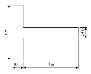
Figure K-1. Landing direction indicator
GM1 ADR-DSN.K.495 Landing direction indicator
ED Decision 2014/013/R
The landing ‘T’ may be constructed of wood or other light material and its dimensions may correspond to those shown in Figure K-1. It may be painted white or orange. The landing ‘T’ should be mounted on a cement concrete pedestal adequately reinforced with steel bars to avoid cracks resulting from unequal settlement. The surface of the pedestal should be finished smooth with a steel trowel and coated with paint of appropriate colour. The colour of the pedestal should be chosen to contrast with the colour of the landing ‘T’. Before fastening the landing ‘T’ base to the concrete pedestal, the mounting bolts should be checked for correct spacing. The landing ‘T’ should be assembled and mounted in accordance with the manufacturer’s installation instructions. It should be free to move about a vertical axis so that it can be set in any direction. Where required for use at night, the landing ‘T’ should either be illuminated or outlined by white lights.
CS ADR-DSN.K.500 Signalling lamp
ED Decision 2014/013/R
(a)A signalling lamp should be provided at a controlled aerodrome in the aerodrome control tower.
(b)Characteristics:
(1)A signalling lamp should be capable of producing red, green and white signals, and of:
(i)being aimed manually at any target as required; and
(ii)giving a signal in any one colour followed by a signal in either of the two other colours.
(2)The beam spread should be not less than 1° or greater than 3°, with negligible light beyond 3°. When the signalling lamp is intended for use in the daytime, the intensity of the coloured light should be not less than 6 000 cd.
GM1 ADR-DSN.K.500 Signalling lamp
ED Decision 2014/013/R
When selecting the green light, use should be made of the restricted boundary of green as specified in GM1 ADR-DSN.U.930(a).
CS ADR-DSN.K.505 Signal panels and signal area
ED Decision 2014/013/R
intentionally left blank
GM1 ADR-DSN.K.505 Signal panels and signal area
ED Decision 2014/013/R
(a)A signal panels and signal area should be provided when visual ground signals are used to communicate with aircraft in flight.
(b)A signal panel and signal area may be needed when the aerodrome does not have an aerodrome control tower or an aerodrome flight information service unit, or when the aerodrome is used by aeroplanes not equipped with radio. Visual ground signals may also be useful in the case of failure of two-way radio communication with aircraft. It should be recognised, however, that the type of information which may be conveyed by visual ground signals should normally be available in AIP or NOTAM. The potential need for visual ground signals should, therefore, be evaluated before deciding to provide a signal area.
(c)ICAO Annex 2, Appendix 1, specifies the shape, colour and use of visual ground signals.
CS ADR-DSN.K.510 Location of signal panels and signal area
ED Decision 2014/013/R
intentionally left blank
GM1 ADR-DSN.K.510 Location of signal panels and signal area
ED Decision 2014/013/R
A signal area should be located so as to be visible for all angles of azimuth above an angle of 10° above the horizontal when viewed from a height of 300 m.
CS ADR-DSN.K.515 Characteristics of signal panels and signal area
ED Decision 2014/013/R
intentionally left blank
GM1 ADR-DSN.K.515 Characteristics of signal panels and signal area
ED Decision 2016/027/R
(a)The signal area should be an even horizontal surface at least 9 m square.
(b)The signal area should be constructed of cement concrete reinforced with an adequate quantity of steel to avoid cracks resulting from unequal settlement. The top surface should be finished smooth with a steel trowel and coated with paint of appropriate colour. The colour of the signal area should be chosen to contrast with the colours of the signal panels to be displayed thereon. More guidance is given in ICAO Doc 9157, Aerodrome Design Manual Part 4, Visual Aids, Chapter 3.
(c)The colour of the signal area should be chosen to contrast with the colours of the signal panels used, and it should be surrounded by a white border not less than 0.3 m wide.
[Issue: ADR-DSN/3]
CHAPTER L — VISUAL AIDS FOR NAVIGATION (MARKINGS)
CS ADR-DSN.L.520 General — Colour and conspicuity
ED Decision 2014/013/R
Markings should be of a conspicuous colour and contrast with the surface on which they are laid.
(a)Runway markings should be white.
(b)Markings for taxiways, runway turn pads, and aircraft stands should be yellow.
(c)Apron safety lines should be of a conspicuous colour which should contrast with that used for aircraft stand markings.
(d)When it is operationally necessary to apply temporary runway or taxiway markings, those markings should comply with the relevant CS.
GM1 ADR-DSN.L.520 General – Colour and conspicuity
ED Decision 2016/027/R
(a)Where there is insufficient contrast between the marking and the pavement surface, the marking should include an appropriate border.
(1)This border should be white or black;
(2)It is preferable that the risk of uneven friction characteristics on markings be reduced in so far as practicable by the use of a suitable kind of paint; and
(3)Markings should consist of solid areas or a series of longitudinal stripes providing an effect equivalent to the solid areas.
(4)Guidance on reflective materials is given in the ICAO Doc 9157, Aerodrome Design Manual, Part 4, Visual Aids.
(b)At aerodromes where operations take place at night, pavement markings should be made with reflective materials designed to enhance the visibility of the markings.
[Issue: ADR-DSN/3]