
Filters
CS ADR-DSN.L.525 Runway designation marking
ED Decision 2016/027/R
(a)Applicability: A runway designation marking should be provided at the thresholds of a runway.
(b)Location and positioning: A runway designation marking should be located at a threshold as shown in Figure L-1 as appropriate.
(c)Characteristics:
(1)A runway designation marking should consist of a two-digit number and on parallel runways should be supplemented with a letter.
(i)On a single runway, dual parallel runways and triple parallel runways, the two-digit number should be the whole number nearest the one-tenth of the magnetic North when viewed from the direction of approach.
(ii)On four or more parallel runways, one set of adjacent runways should be numbered to the nearest one-tenth magnetic azimuth and the other set of adjacent runways numbered to the next nearest one-tenth of the magnetic azimuth.
(iii)When a runway designation marking consists of a single digit number, it should be preceded by a zero.
(2)In the case of parallel runways, each runway designation number should be supplemented by a letter as follows, in the order shown from left to right when viewed from the direction of approach:
(i)for two parallel runways: ‘L’ ‘R’;
(ii)for three parallel runways: ‘L’ ‘C’ ‘R’;
(iii)for four parallel runways: ‘L’ ‘R’ ‘L’ ‘R’;
(iv)for five parallel runways: ‘L’ ‘C’ ‘R’ ‘L’ ‘R’ or
‘L’ ‘R’ ‘L’ ‘C’ ‘R’; and
(v)for six parallel runways: ‘L’ ‘C’ ‘R’ ‘L’ ‘C’ ‘R’.
(3)The numbers and letters should be in the form and proportion shown in Figure L-2. The dimensions should be not less than those shown in Figure L-2. Where the numbers are incorporated in the threshold marking, larger dimensions should be used in order to fill adequately the gap between the stripes of the threshold marking.
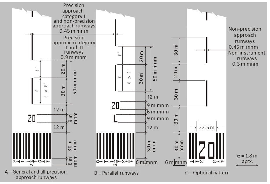
Figure L-1. Runway designation, centre line and threshold markings
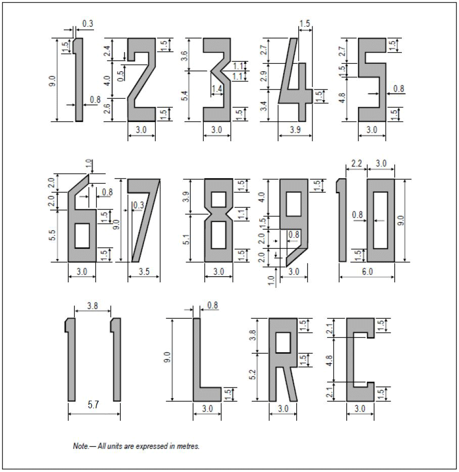
Figure L-2. Form and proportions of numbers and letters for runway designation markings
[Issue: ADR-DSN/3]
GM1 ADR-DSN.L.525 Runway designation marking
ED Decision 2014/013/R
intentionally left blank
CS ADR-DSN.L.530 Runway centre line marking
ED Decision 2016/027/R
(a)Applicability: A runway centre line marking should be provided on a paved runway.
(b)Location: A runway centre line marking should be located along the centre line of the runway between the runway designation marking as shown in Figure L-1, except when interrupted as given in CS ADR-DSN.L.560.
(c)Characteristics:
(1)A runway centre line marking should consist of a line of uniformly spaced stripes and gaps. The length of a stripe plus a gap should be not less than 50 m or more than 75 m. The length of each stripe should be at least equal to the length of the gap or 30 m, whichever is greater.
(2)The width of the stripes should be not less than:
(i)0.90 m on precision approach Category II and III runways;
(ii)0.45 m on non-precision approach runways where the code number is 3 or 4, and precision approach Category I runways; and
(iii)0.30 m on non-precision approach runways where the code number is 1 or 2, and on non-instrument runways.
[Issue: ADR-DSN/3]
GM1 ADR-DSN.L.530 Runway centre line marking
ED Decision 2014/013/R
For the centre line marking the 30 m length of and gap between stripes may be adjusted to take into consideration the runway thresholds locations.
CS ADR-DSN.L.535 Threshold marking
ED Decision 2016/027/R
(a)Applicability: A threshold marking should be provided at the threshold of a runway.
(b)Characteristics:
(1)The stripes of the threshold marking should commence 6 m from the threshold.
(2)A runway threshold marking should consist of a pattern of longitudinal stripes of uniform dimensions disposed symmetrically about the centre line of a runway as shown in Figure L-1(A) and L-1(B) for a runway width of 45 m. The number of stripes should be in accordance with the runway width as follows:
Runway width | Number of stripes |
18 m | 4 |
23 m | 6 |
30 m | 8 |
45 m | 12 |
60 m | 16 |
except that on non-precision approach and non-instrument runways 45 m or greater in width, they may be as shown in Figure L-1(C).
(3)The stripes should extend laterally to within 3 m of the edge of a runway or to a distance of 27 m on either side of a runway centre line, whichever results in the smaller lateral distance.
(4)Where a runway designation marking is placed within a threshold marking, there should be a minimum of three stripes on each side of the centre line of the runway.
(5)Where a runway designation marking is placed above a threshold marking, the stripes should be continued across the runway. The stripes should be at least 30 m long and approximately 1.80 m wide with spacings of approximately 1.80 m between them. Where the stripes are continued across a runway, a double spacing should be used to separate the two stripes nearest the centre line of the runway, and in the case where the designation marking is included within the threshold marking, this spacing should be 22.5 m.
(c)Displaced threshold:
(1)Where a threshold is displaced from the extremity of a runway or where the extremity of a runway is not square with the runway centre line, a transverse stripe as shown in Figure L-3(B) should be added to the threshold marking.
(2)A transverse stripe should be not less than 1.80 m wide.
(3)Where a runway threshold is permanently displaced, arrows conforming to Figure L-3(B) should be provided on the portion of the runway before the displaced threshold.
(4)When a runway threshold is temporarily displaced from the normal position, it should be marked as shown in Figure L-3(A) or L-3(B), and all markings prior to the displaced threshold should be obscured except the runway centre line marking which should be converted to arrows.
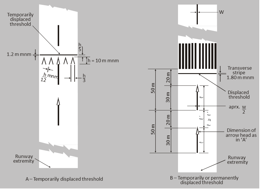
Figure L-3. Displaced threshold markings
[Issue: ADR-DSN/3]
GM1 ADR-DSN.L.535 Threshold marking
ED Decision 2014/013/R
intentionally left blank
CS ADR-DSN.L.540 Aiming point marking
ED Decision 2014/013/R
(a)Applicability:
(1)An aiming point marking should be provided at each approach end of an instrument runway where the code number is 2, 3, or 4.
(2)An aiming point marking should be provided when additional conspicuity of the aiming point is required at each approach end of:
(i)a non-instrument runway where the code number is 3 or 4,
(ii)an instrument runway where the code number is 1.
(b)Characteristics. The aiming point marking should commence no closer to the threshold than the distance indicated in the appropriate column of Table L-1, except that, on a runway equipped with a PAPI system, the beginning of the marking should be coincident with the visual approach slope origin.
Location and dimensions | Landing distance available | |||
Less than 800 m | 800 m up to but not including 1 200 m | 1 200 m up to but not including 2 400 m | 2 400 m and above | |
(1) | (2) | (3) | (4) | (5) |
Distance from threshold to beginning of markinga | 150 m | 250 m | 300 m | 400 m |
Length of stripeb | 30-45 m | 30-45 m | 45-60 m | 45-60 m |
Width of stripe | 4 m | 6 m | 6-10 mc | 6-10 mc |
Lateral spacing between inner sides of stripes | 6 md | 9 md | 18-22.5 m | 18-22.5 m |
aWhere a PAPI system is provided for the runway, the beginning of the marking should be coincident with the visual approach slope origin. bWhere greater dimensions of the specified ranges are intended to be used where increased conspicuity is required. cWhere lateral spacing may be varied within these limits to minimise the contamination of the marking by rubber deposits. dThese figures were deduced by reference to the outer main gear wheel span which is element 2 of the aerodrome reference code | ||||
Table L-1. Location and dimensions of aiming point marking
(c)An aiming point marking should consist of two conspicuous stripes. The dimensions of the stripes and the lateral spacing between their inner sides should be in accordance with the provisions of the appropriate column of Table L-1.
GM1 ADR-DSN.L.540 Aiming point marking
ED Decision 2017/021/R
For runways with widths of 30 m, the width of the rectangular stripes of the aiming point marking and the lateral spacing between the inner sides of the stripes may be adjusted in proportion to the available runway width to avoid overlapping of the aiming point marking with the runway side stripe marking.
[Issue: ADR-DSN/4]
CS ADR-DSN.L.545 Touchdown zone marking
ED Decision 2016/027/R
(a)Applicability:
(1)A touchdown zone marking should be provided in the touchdown zone of a paved precision approach runway where the code number is 2, 3, or 4.
(2)A touchdown zone marking should be provided in the touchdown zone of a paved non-precision approach or non-instrument runway where the code number is 3 or 4 and additional conspicuity of the touchdown zone is desirable.
(b)Location: A touchdown zone marking should consist of pairs of rectangular markings symmetrically disposed about the runway centre line with the number of such pairs related to the landing distance available and, where the marking is to be displayed at both the approach directions of a runway, the distance between the thresholds, as follows:
Landing distance available or the distance between thresholds | Pair(s) of markings |
less than 900 m | 1 |
900 m up to but not including 1 200 m | 2 |
1 200 m up to but not including 1 500 m | 3 |
1 500 m up to but not including 2 400 m | 4 |
2 400 m or more | 6 |
(c)Characteristics:
(1)A touchdown zone marking should conform to the patterns shown in Figure L-4. For the pattern shown in Figure L-4(A), the markings should be not less than 22.5 m long and 3 m wide. For the pattern shown in Figure L-4(B), each stripe of each marking should be not less than 22.5 m long and 1.8 m wide with spacing of 1.5 m between adjacent stripes.
(2)The lateral spacing between the inner sides of the rectangles should be equal to that of the aiming point marking where provided. Where an aiming point marking is not provided, the lateral spacing between the inner sides of the rectangles should correspond to the lateral spacing specified for the aiming point marking in Table L-1 (columns (2), (3), (4), or (5), as appropriate). The pairs of markings should be provided at longitudinal spacings of 150 m beginning from the threshold, except that pairs of touchdown zone markings coincident with or located within 50 m of an aiming point marking should be deleted from the pattern.
(3)On a non-precision approach runway where the code number is 2, an additional pair of touchdown zone marking stripes should be provided 150 m beyond the beginning of the aiming point marking.
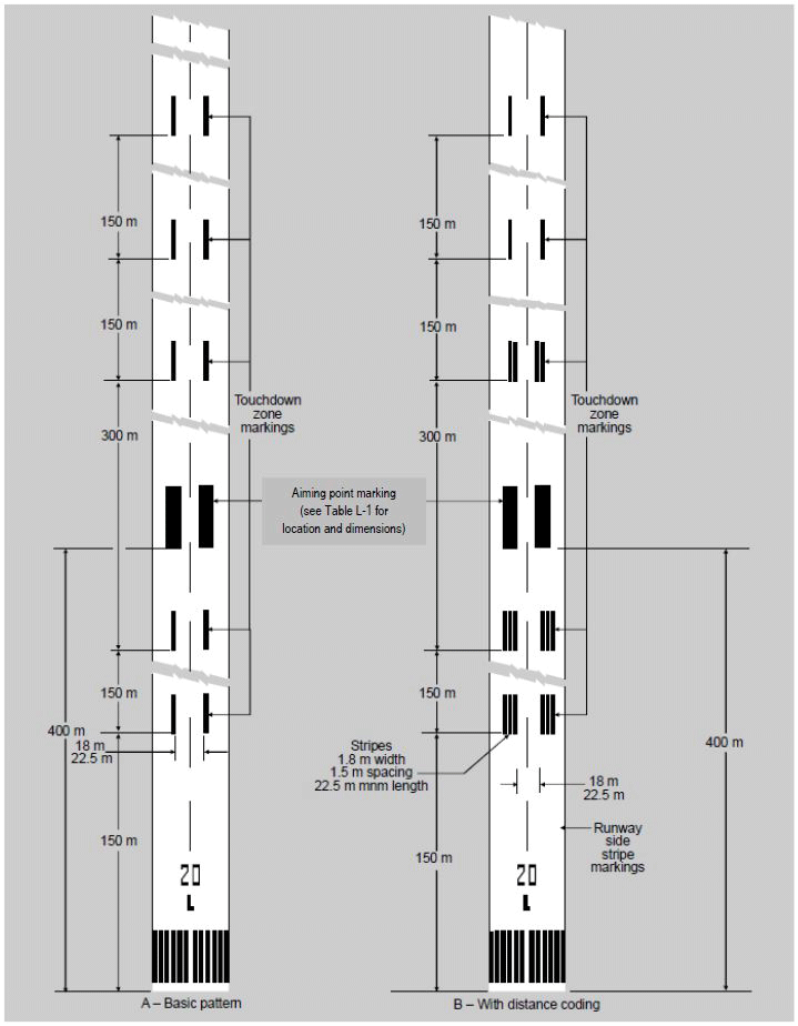
Figure L-4. Aiming point and touchdown zone markings (illustrated for a runway with a length of 2 400 m or more)
[Issue: ADR-DSN/3]
GM1 ADR-DSN.L.545 Touchdown zone marking
ED Decision 2014/013/R
(a)In order to give information regarding the overall extension of a distance coding touchdown marking, as specified in CS ADR-DSN.L.545, the last pair of markings after the threshold should consist of two single stripes, and the other pairs should correspond to the patterns shown in Figure L-4.
(b)Such sequential layout gives intuitive information about the extension of the touchdown zone and, as a consequence, of the LDA or of the distance between thresholds.
CS ADR-DSN.L.550 Runway side stripe marking
ED Decision 2014/013/R
(a)Applicability:
(1)A runway side stripe marking should be provided between the thresholds of a runway where there is a lack of contrast between the runway edges and the shoulders or the surrounding terrain.
(2)A runway side stripe marking should be provided on a precision approach runway irrespective of the contrast between the runway edges and the shoulders or the surrounding terrain.
(b)Location and characteristics:
(1)A runway side stripe marking should consist of two stripes, one placed along each edge of the runway with the outer edge of each stripe approximately on the edge of the runway, except that, where the runway is greater than 60 m in width, the stripes should be located 30 m from the runway centre line.
(2)Where a runway turn pad is provided, the runway side stripe marking should be continued between the runway and the runway turn pad.
(3)A runway side stripe should have an overall width of at least 0.9 m on runways 30 m or more in width and at least 0.45 m on narrower runways.
GM1 ADR-DSN.L.550 Runway side stripe marking
ED Decision 2014/013/R
When turn pads are not available at the end of a runway for back-track manoeuvres and threshold is displaced, in order to better identify full-strength bearing surface, it may be useful to display specific dashed markings as showed by Figure GM-L-1 and with dimensions described in Table GM-L-1.
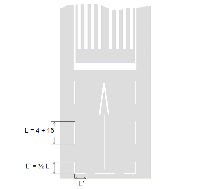
Figure GM-L-1. Dashed runway side stripe marking
Runway width (m) | Single dash dimensions | |
Length (minimum m) | Width (m) | |
60 | 15 | 0.45 |
45 | 15 | 0.45 |
30 | 10 | 0.45 |
23 | 6 | 0.25 |
18 | 4 | 0.25 |
Note:The length of the gap is as much as possible equal, but not longer, to the length of the corresponding marking | ||
Table GM-L-1. Dashed runway side stripe markings
CS ADR-DSN.L.555 Taxiway centre line marking
ED Decision 2022/006/R
(a)Applicability:
(1)Taxiway centre line marking should be provided on a taxiway, de-icing/anti-icing facility and apron in such a way as to provide continuous guidance between the runway centre line and aircraft stands.
(2)Taxiway centre line marking should be provided on a runway when the runway is part of a standard taxi-route and where the taxiway centre line is not coincident with the runway centre line.
(b)Characteristics:
(1)On a straight section of a taxiway, the taxiway centre line marking should be located along the taxiway centre line.
(2)On a taxiway curve, the marking should continue from the straight portion of the taxiway at a constant distance from the outside edge of the curve.
(3)At an intersection of a taxiway with a runway, where the taxiway serves as an exit from the runway, the taxiway centre line marking should be curved into the runway centre line marking as shown in Figure L-5. The taxiway centre line marking should be extended parallel to the runway centre line marking for a distance of at least 60 m beyond the point of tangency where the code number is 3 or 4, and for a distance of at least 30 m where the code number is 1 or 2.
(4)Where taxiway centre line marking is provided in accordance with (a)(2) above, the marking should be located on the centre line of the designated taxiway.
(5)A taxiway centre line marking should be at least 15 cm in width and continuous in length except where it intersects with a runway-holding position marking or an intermediate holding position marking as shown in Figure L-5. Taxiway markings (shown with basic runway markings).
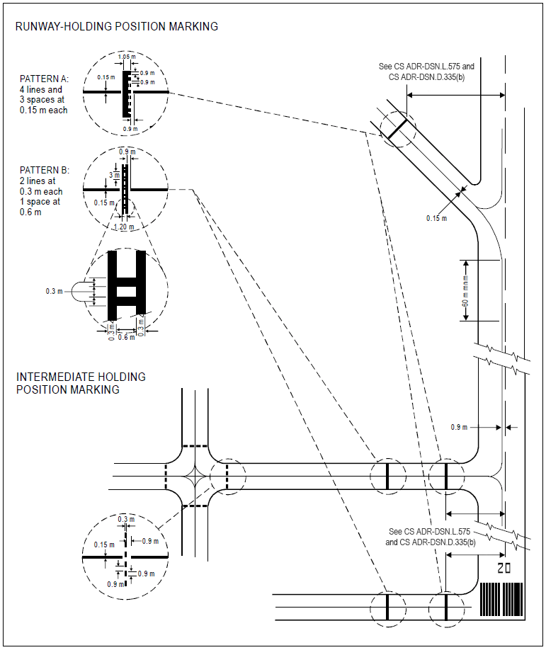
Figure L-5. Taxiway markings (shown with basic runway markings)
[Issue: ADR-DSN/3]
[Issue: ADR-DSN/6]
GM1 ADR-DSN.L.555 Taxiway centre line marking
ED Decision 2016/027/R
The term ‘continuous guidance’ is not intended to require that taxiway centre line markings are provided onto aircraft stands. Instead, it is intended that the centre line marking be provided on taxiways leading to aircraft stands or other apron areas from which visual cues or other means exist, such as lead-in arrows and stand number indicators, to enable aircrew to manoeuvre the aircraft onto a stand or other parking area.
[Issue: ADR-DSN/3]
CS ADR-DSN.L.560 Interruption of runway markings
ED Decision 2014/013/R
(a)At an intersection of two (or more) runways, the markings of the more important runway, except for the runway side stripe marking, should be displayed and the markings of the other runway(s) should be interrupted. The runway side stripe marking of the more important runway should be either continued across the intersection or interrupted.
(b)The order of importance of runways for the display of runway markings should be as follows:
(1)precision approach runway;
(2)non-precision approach runway; and
(3)non-instrument runway.
(c)At an intersection of a runway and taxiway the markings of the runway should be displayed and the markings of the taxiway interrupted, except that runway side stripe markings should be either continued across the intersection or interrupted.
GM1 ADR-DSN.L.560 Interruption of runway markings
ED Decision 2017/021/R
(a)At an intersection of a runway and taxiway, the runway side stripe marking should be either continued across the intersection or interrupted. The interruption means one of the following:
(1)the runway side stripe marking stops at the point where the taxiway fillet starts at either side of the taxiway (see Figure GM-L-2(A)); or
(2)the runway side stripe marking stops at the point where the extended line of the taxiway edge crosses the runway (see Figure GM-L-2(B)); or
(3)the runway side stripe marking stops at a short distance on either side of the taxiway centre line marking in order to allow visible and continuous taxiway centre line marking guidance (see Figure GM-L-2(C)); or
(4)the taxiway centre line marking overlays and therefore interrupts a continuous runway side stripe marking (see Figure GM-L-2(D)).
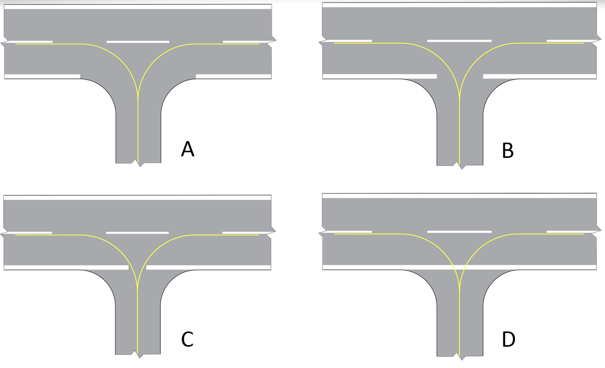
Figure GM-L-2. Illustration of runway side stripe marking interruption
(b)The overall perception of the runway side stripe marking depends on conspicuity needs and local conditions, such as the number, location and disposition of runway/taxiway intersections, nature of the surrounding terrain, operational needs at aerodrome, weather, etc.
[Issue: ADR-DSN/4]
CS ADR-DSN.L.565 Runway turn pad marking
ED Decision 2017/021/R
(a)Applicability: Where a runway turn pad is provided, a runway turn pad marking should be provided for continuous guidance to enable an aeroplane to complete a 180-degree turn and align with the runway centre line.
(b)Characteristics:
(1)The runway turn pad marking should be curved from the runway centre line into the turn pad. The radius of the curve should be compatible with the manoeuvring capability and normal taxiing speeds of the aeroplanes for which the runway turn pad is intended.
(2)The intersection angle of the runway turn pad marking with the runway centre line should not be greater than 30 degrees.
(3)The runway turn pad marking should be extended parallel to the runway centre line marking for a distance of at least 60 m beyond the point of tangency where the code number is 3 or 4, and for a distance of at least 30 m where the code number is 1 or 2.
(4)A runway turn pad marking should guide the aeroplane in such a way as to allow a straight portion of taxiing before the point where a 180-degree turn is to be made. The straight portion of the runway turn pad marking should be parallel to the outer edge of the runway turn pad.
(5)The design of the curve allowing the aeroplane to negotiate a 180-degree turn should be based on a nose wheel steering angle not exceeding 45 degrees.
(6)The design of the turn pad marking should be such that when the cockpit of the aeroplane remains over the runway turn pad marking, the clearance distance between any wheel of the aeroplane landing gear and the edge of the runway turn pad should be not less than those specified in CS ADR-DSN.B.095(c).
(7)A runway turn pad marking should be at least 15 cm in width and continuous in length.
[Issue: ADR-DSN/4]
GM1 ADR-DSN.L.565 Runway turn pad marking
ED Decision 2017/021/R
Where a runway turn pad is not provided, a marking for continuous guidance to enable an aeroplane to complete a 180-degree turn and align with the runway centre line may be provided. Such marking should be yellow, at least 15 cm in width and continuous in length.
[Issue: ADR-DSN/4]
CS ADR-DSN.L.570 Enhanced taxiway centre line marking
ED Decision 2022/006/R
(a)Where provided, an enhanced taxiway centre line marking should be installed at each taxiway/runway intersection where it is necessary to denote the proximity of a runway-holding position.
(b)Characteristics:
(1)Enhanced taxiway centre line marking should be as shown in Figure L-6. An enhanced taxiway centre line marking should extend from the runway-holding position Pattern A (as defined in Figure L-5) to a distance of up to 47 m in the direction of travel away from the runway (see Figure L-6(a)).
(2)If the enhanced taxiway centre line marking intersects another runway-holding position marking, such as for a precision approach Category II or III runway, that is located within 47 m of the first runway-holding position marking, the enhanced taxiway centre line marking should be interrupted 0.9 m prior to and after the intersected runway-holding position marking. The enhanced taxiway centre line marking should continue beyond the intersected runway-holding position marking for at least three dashed line segments or 47 m from start to finish, whichever is greater (see Figure L-6(b)).
(3)If the enhanced taxiway centre line marking continues through a taxiway/taxiway intersection that is located within 47 m of the runway-holding position marking, the enhanced taxiway centre line marking should be interrupted 1.5 m prior to and after the point where the intersected taxiway centre line crosses the enhanced taxiway centre line. The enhanced taxiway centre line marking should continue beyond the taxiway/taxiway intersection for at least three dashed line segments or 47 m from start to finish, whichever is greater (see Figure L-6(c)).
(4)Where two taxiway centre lines converge at or before the runway-holding position marking, the inner dashed line should not be less than 3 m in length (see Figure L-6(d)).
(5)Where there are two opposing runway-holding position markings and the distance between the markings is less than 94 m, the enhanced taxiway centre line markings should extend over this entire distance. The enhanced taxiway centre line markings should not extend beyond either runway-holding position marking (see Figure L-6(e)).
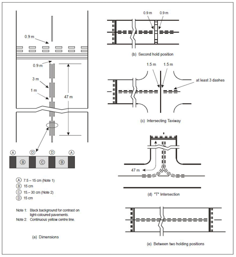
Figure L-6. Enhanced taxiway centre line marking
[Issue: ADR-DSN/3]
[Issue: ADR-DSN/6]
GM1 ADR-DSN.L.570 Enhanced taxiway centre line marking
ED Decision 2016/027/R
The provision of enhanced taxiway centre line marking may form part of runway incursion prevention measures.
[Issue: ADR-DSN/3]
CS ADR-DSN.L.575 Runway-holding position marking
ED Decision 2016/027/R
A runway-holding position marking should be displayed along a runway-holding position.
(a)Characteristics:
(1)At an intersection of a taxiway and a non-instrument, non-precision approach or take-off runway, the runway-holding position marking should be as shown in Figure L-5, pattern A.
(2)Where a single runway-holding position is provided at an intersection of a taxiway and a precision approach Category I, II or III runway, the runway-holding position marking should be as shown in Figure L-5, pattern A.
(3)Where two or three runway-holding positions are provided at such an intersection, the runway-holding position marking closer (closest) to the runway should be as shown in Figure L-5, pattern A, and the markings farther from the runway should be as shown in Figure L-5, pattern B.
(4)The runway-holding position marking displayed at a runway-holding position established in accordance with CS ADR-DSN.D.335(b)(1) should be as shown in Figure L-5, pattern A.
(5)Where increased conspicuity of the runway-holding position is required, the runway-holding position marking should be as shown in Figure L-7, pattern A or pattern B, as appropriate.
(6)Where a pattern B runway-holding position marking is located on an area where it would exceed 60 m in length, a mandatory instruction marking containing the term ‘CAT II’ or ‘CAT III’ as appropriate should be marked on the surface at the ends of the runway-holding position marking and at equal intervals of 45 m maximum between successive marks. The letters should be not less than 1.8 m high and should be placed not more than 0.9 m on the holding side of the runway holding position marking.
(7)The runway-holding position marking displayed at a runway/runway intersection should be perpendicular to the centre line of the runway forming part of the standard taxi-route. The pattern of the marking should be as shown in Figure L-7, pattern A.
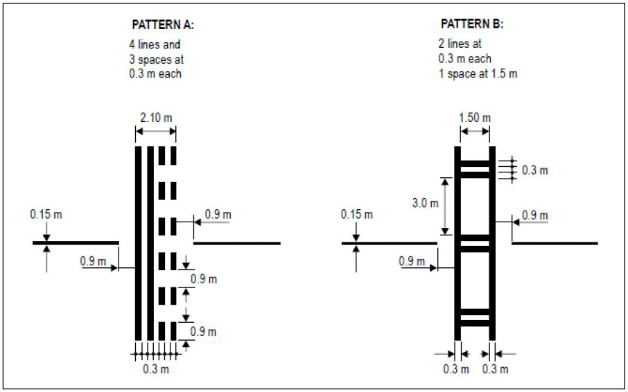
Figure L-7. Runway-holding position markings
[Issue: ADR-DSN/3]
GM1 ADR-DSN.L.575 Runway-holding position marking
ED Decision 2014/013/R
When the Runway-holding position marking is supplemented with the term ‘CAT II’ or ‘CAT III’ on the areas or taxiways exceeding 60 m in accordance with CS ADR-DSN.L.575(a)(6) and should be placed along with the Mandatory instruction marking in accordance with CS ADR-DSN.L.605 both markings should be equally and symmetrically placed one next to another.
CS ADR-DSN.L.580 Intermediate holding position marking
ED Decision 2016/027/R
(a)Applicability:
(1)An intermediate holding position marking should be displayed along an intermediate holding position.
(2)An intermediate holding position marking should be displayed at the exit boundary of a remote de-icing/anti-icing facility adjoining a taxiway.
(b)Location:
(1)Where an intermediate holding position marking is displayed at an intersection of two taxiways, it should be located across the taxiway at sufficient distance from the near edge of the intersecting taxiway to ensure safe clearance between taxiing aircraft. It should be coincident with a stop bar or intermediate holding position lights where provided.
(2)The distance between an intermediate holding position marking at the exit boundary of a remote de-icing/anti-icing facility and the centre line of the adjoining taxiway should not be less than the dimension specified in the table below.
Code letter | Distance (metres) |
A | 15.5 |
B | 20 |
C | 26 |
D | 37 |
E | 43.5 |
F | 51 |
(c)Characteristics: An intermediate holding position marking should consist of a single broken line as shown in Figure L-5.
[Issue: ADR-DSN/3]
GM1 ADR-DSN.L.580 Intermediate holding position marking
ED Decision 2014/013/R
intentionally left blank
CS ADR-DSN.L.585 VOR aerodrome checkpoint marking
ED Decision 2016/027/R
(a)Applicability: When a VOR aerodrome check-point is established, it should be indicated by a VOR aerodrome check-point marking and sign.
(b)Location: A VOR aerodrome check-point marking should be centred on the spot at which an aircraft is to be parked to receive the correct VOR signal.
(c)Characteristics:
(1)A VOR aerodrome check-point marking should consist of a circle 6 m in diameter and have a line width of 15 cm (see Figure L-8(A)).
(2)When it is preferable for an aircraft to be aligned in a specific direction, a line should be provided that passes through the centre of the circle on the desired azimuth. The line should extend 6 m outside the circle in the desired direction of heading and terminate in an arrowhead. The width of the line should be 15 cm (see Figure L-8(B)).
(3)A VOR aerodrome check-point marking should differ from the colour used for the taxiway markings and when applicable from a contrasting viewpoint, be white in colour.

Figure L-8. VOR check-point markings
[Issue: ADR-DSN/3]
GM1 ADR-DSN.L.585 VOR aerodrome checkpoint marking
ED Decision 2016/027/R
Further guidance on the selection of sites for VOR aerodrome checkpoints is given in ICAO Annex 10, Volume I, Attachment E.
[Issue: ADR-DSN/3]
CS ADR-DSN.L.590 Aircraft stand marking
ED Decision 2014/013/R
(a)Applicability: Aircraft stand markings should be provided for designated parking positions on an apron and on a de-icing/anti-icing facility.
(b)General characteristics: Aircraft stand markings should include such elements as stand identification, lead-in line, turn bar, turning line, alignment bar, stop line and lead-out line as are required by the parking configuration and to complement other parking aids.
(c)Aircraft stand identification:
(1)An aircraft stand identification (letter and/or number) should be included in the lead-in line a short distance after the beginning of the lead-in line. The height of the identification should be adequate to be readable from the cockpit of aircraft using the stand.
(2)Identification of the aircraft for which each set of markings is intended, should be added to the stand identification where two sets of aircraft stand markings are superimposed on each other in order to permit more flexible use of the apron and safety would be impaired if the wrong marking was followed.
(d)Lead-in, turning, and lead-out lines:
(1)Lead-in, turning, and lead-out lines should, as far as practicable, be continuous in length and have a width of not less than 15 cm. Where one or more sets of stand markings are superimposed on a stand marking, the lines should be continuous for the most demanding aircraft and broken for other aircraft.
(2)The curved portions of lead-in, turning, and lead-out lines should have radii appropriate to the most demanding aircraft type for which the markings are intended.
(3)Where it is intended that an aircraft proceeds in one direction only, arrows pointing in the direction to be followed should be added as part of the lead-in and lead-out lines.
(e)Alignment bar: An alignment bar should be placed so as to be coincident with the extended centre line of the aircraft in the specified parking position and visible to the pilot during the final part of the parking manoeuvre. It should have a width of not less than 15 cm.
(f)Turn bar and stop line:
(1)A turn bar should be located at right angles to the lead-in line, abeam the left pilot position at the point of initiation of any intended turn. It should have a length and width of not less than 6 m and 15 cm respectively, and include an arrowhead to indicate the direction of turn.
(2)A stop line should be located at right angles to the alignment bar, abeam the left pilot position at the intended point of stop. It should have a length and width of not less than 6 m and 15 cm respectively.
(3)If more than one turn bar and/or stop line is required, they should be designated for the appropriate aircraft types.
GM1 ADR-DSN.L.590 Aircraft stand marking
ED Decision 2025/004/R
(a)The distances to be maintained between the stop line and the lead-in line may vary according to different aircraft types, taking into account the pilot’s field of view.
(b)Apron markings are installed to support the safe operation of aircraft on stands and apron areas. Where appropriate procedures are employed, for example the presence of a marshaller, markings may not be required, giving flexibility of operations.
[Issue: ADR-DSN/7]
CS ADR-DSN.L.595 Apron safety lines
ED Decision 2014/013/R
(a)Applicability: Apron safety lines should be provided on an apron as required by the parking configurations and ground facilities.
(b)Location: Apron safety lines should be located so as to define the areas intended for use by ground vehicles and other aircraft servicing equipment to provide safe separation from aircraft.
(c)Characteristics:
(1)Apron safety lines should include such elements as wing tip clearance lines and service road boundary lines as required by the parking configurations and ground facilities.
(2)Apron safety lines should be of a conspicuous colour which should contrast with that used for aircraft stand markings.
(3)An apron safety line should be continuous in length and at least 10 cm in width.
GM1 ADR-DSN.L.595 Apron safety lines
ED Decision 2016/027/R
(a)Ground equipment and vehicles should be kept outside predetermined limits when aircraft are manoeuvring or when the equipment is left unattended.
(b)Safety lines are required on an apron to mark the limits of parking areas for ground equipment, apron service roads and passengers’ paths, etc. These lines are narrower and of a different colour to differentiate them from the guidelines used for aircraft.
(1)Wing tip clearance lines. These lines should delineate the safety zone clear of the path of the critical aeroplane wing tip. The line should be drawn at appropriate distance outside the normal path of the wing tip of the critical aeroplane;
(2)Equipment limit lines. These lines are used to indicate the limits of areas which are intended for parking vehicles and aircraft servicing equipment when they are not in use.
(c)Several methods may be used to identify which side of a safety line is safe for storage of such vehicles and equipment:
(1)Spurs or an additional line (a discontinuous line of the same colour or a continuous line of a different conspicuous colour) may be provided on one side of the safety line. The side on which such spurs or an additional line is located is considered safe for parking vehicles and equipment;
(2)The words ‘Equipment Limit’ may be painted on the side used by ground equipment and readable from that side;
(3)Passenger path lines. These lines are used to indicate to passengers and escorting personnel the route that needs to be followed, when walking on the apron, in order to be clear of hazards. A pair of lines with zebra hatching between them may be used.
[Issue: ADR-DSN/3]
CS ADR-DSN.L.597 Apron service road marking
ED Decision 2016/027/R
(a)Applicability: The limits of an apron service road, should be defined by apron service road markings.
(b)Location: Apron service road markings should define the areas intended for use by ground vehicles and other aircraft servicing equipment to provide safe separation from aircraft.
(c)Characteristics:
(1)Apron service road markings should be white.
(2)Apron service road markings should be continuous in length on the edges, continuous or broken in the middle, as appropriate, and at least 10 cm in width.
(3)When an apron service road crosses a taxiway or aircraft stand taxilane, the apron service road edge marking should be laterally dashed along the crossing. The stripes should be 1.0 m in length, and their width should be equal to the width of the continuous part of the marking.
(d)Apron service road markings should be discontinued when they intersect with other markings on an apron. The interrupted gap should be not more than 1 m on each side from the edge of the interested marking.
[Issue: ADR-DSN/3]
GM1 ADR-DSN.L.597 Apron service road marking
ED Decision 2016/027/R
(a)The term service road encompasses also other types of roads, such as the perimeter service roads, which are used to provide access to security or maintenance services etc. of the aerodrome. However, such types of service roads do not fall under the term ‘apron service road’.
(b)When an apron service road crosses a taxiway, a separate road-holding position sign, in accordance with CS ADR-DSN.N.800, or road-holding position marking, in accordance with CS ADR-DSN.L.600, should indicate that vehicles are required to stop.
(c)Markings located on an apron are prescribed in CS ADR-DSN.L.555, CS ADR-DSN.L.590 and CS ADR-DSN.L.595.
[Issue: ADR-DSN/3]
CS ADR-DSN.L.600 Road-holding position marking
ED Decision 2016/027/R
(a)Applicability: A road-holding position marking should be provided at all road entrances or intersections to a runway or a taxiway.
(b)Location:
(1)The road-holding position marking should be located across the road at the holding position.
(2)Where a road intersects a taxiway, a road-holding position marking should be located across the road at the appropriate distance to ensure vehicles remain clear of the taxiway strip.
(c)Characteristics:
(1)The road-holding position marking should be in accordance with the local road traffic regulations.
(2)The road-holding position marking at the intersection of a road with a taxiway should be in accordance with the local traffic regulations for a yield right-of-way or mandatory stop.
[Issue: ADR-DSN/3]
GM1 ADR-DSN.L.600 Road-holding position marking
ED Decision 2016/027/R
(a)Where a road that accesses a runway or a taxiway is unpaved, it may not be possible to install markings. In such cases, a road-holding position signs and/or lights should be installed, combined with appropriate instructions on how the driver of a vehicle should proceed.
(b)Where it is possible to install markings, they should conform to national regulations for traffic sings and markings.
[Issue: ADR-DSN/3]
CS ADR-DSN.L.605 Mandatory instruction marking
ED Decision 2022/006/R
(a)Applicability:
(1)Where a mandatory instruction sign in accordance with CS ADR-DSN.N.780 is not installed, a mandatory instruction marking should be provided on the surface of the pavement.
(2)On taxiways exceeding 60 m in width, or to assist in the prevention of a runway incursion, a mandatory instruction sign should be supplemented by a mandatory instruction marking.
(b)Location:
(1)The mandatory instruction marking on taxiways, where the code letter is A, B, C, or D, should be located across the taxiway equally placed about the taxiway centre line and on the holding side of the runway-holding position marking as shown in Figure L-9(A). The distance between the nearest edge of the marking and the runway-holding position marking or the taxiway centre line marking should be not less than 1 m.
(2)The mandatory instruction marking on taxiways where the code letter is E or F, should be located on the both sides of the taxiway centre line marking and on the holding side of the runway-holding position marking as shown in Figure L-9(B). The distance between the nearest edge of the marking and the runway-holding position marking, or the taxiway centre line marking should be not less than 1 m.
(c)Characteristics:
(1)A mandatory instruction marking should consist of an inscription in white on a red background. Except for a no-entry marking, the inscription should provide information identical to that of the associated mandatory instruction sign.
(2)A no-entry marking should consist of an inscription in white reading NO ENTRY on a red background.
(3)Where there is insufficient contrast between the marking and the pavement surface, the mandatory instruction marking should include an appropriate border, preferably white or black.
(4)The character height should be 4 m for inscriptions where the code letter is C, D, E, or F, and at least 2 m where the code letter is A or B. The inscription should be in the form and proportions shown in Figures L-10A to L-10D.
(5)The background should be rectangular and extend a minimum of 0.5 m laterally and vertically beyond the extremities of the inscription.
(6)The spacing of characters for mandatory instruction marking should be obtained by first determining the equivalent elevated sign character height and then proportioning from the spacing values given in Table N-3.
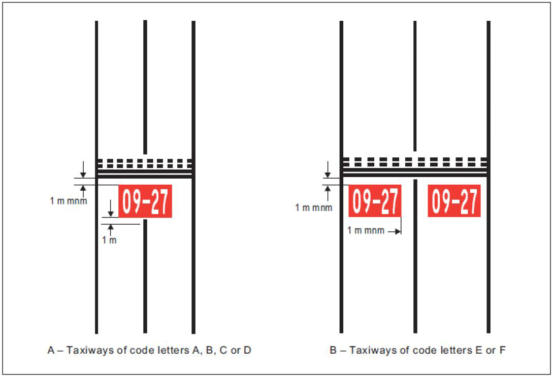
Figure L-9. Mandatory instruction marking
[Issue: ADR-DSN/3]
[Issue: ADR-DSN/4]
[Issue: ADR-DSN/6]
GM1 ADR-DSN.L.605 Mandatory instruction marking
ED Decision 2017/021/R
(a)Except where operationally required, a mandatory instruction marking should not be located on a runway.
(b)The mandatory instruction markings and information markings on pavements are formed as if shadowed (i.e. stretched) from the characters of an equivalent elevated sign by a factor of 2.5, as illustrated in Figure GM-L-3. The shadowing only affects the vertical dimension.
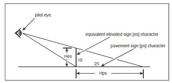
Figure GM-L-3. Illustration of pavement marking spacing calculation
(c)The following example illustrates how the pavement marking spacing is to be calculated:
(1)in the case of runway designator ‘10’, which is to have a height of 4 000 mm (Hps), the equivalent elevated sign character height is 4 000/2.5 = 1 600 mm (Hes);
(2)Table N-3(b) indicates numeral to numeral code 1 and from Table N-3(c) this code has a dimension of 96 mm, for a character height of 400 mm;
(3)the pavement marking spacing for ‘10’ is then (1 600/400) x 96 = 384 mm.
[Issue: ADR-DSN/4]
CS ADR-DSN.L.610 Information marking
ED Decision 2022/006/R
(a)Applicability: Where an information sign in accordance with CS ADR-DSN.N.785 is not installed, an information marking should be displayed on the surface of the pavement.
(b)Characteristics:
(1)An information marking should consist of:
(i)an inscription in yellow upon a black background when it replaces or supplements a location sign; and
(ii)an inscription in black upon a yellow background when it replaces or supplements a direction or destination sign.
(2)Where there is insufficient contrast between the marking background and the pavement surface, the marking should include:
(i)a black border where the inscriptions are in black; and
(ii)a yellow border where the inscriptions are in yellow.
(3)The character height, spacing, and the form and proportions of the inscription should be as for mandatory instruction markings.
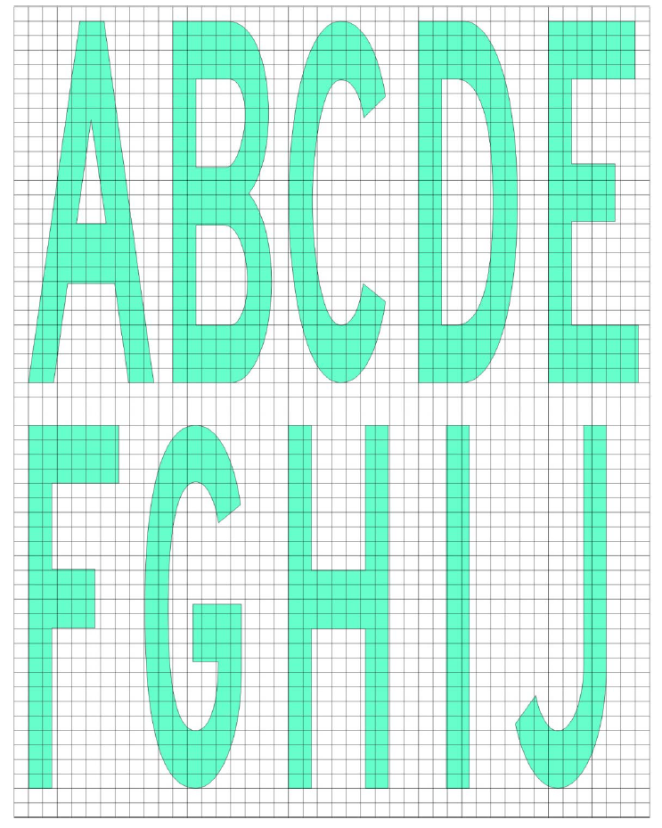
Figure L-10A. Mandatory instruction marking inscription form and proportions

Figure L-10B. Mandatory instruction marking inscription form and proportions
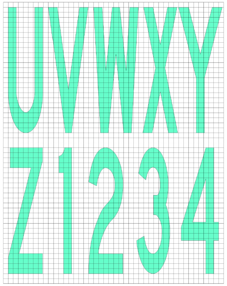
Figure L-10C. Mandatory instruction marking inscription form and proportions
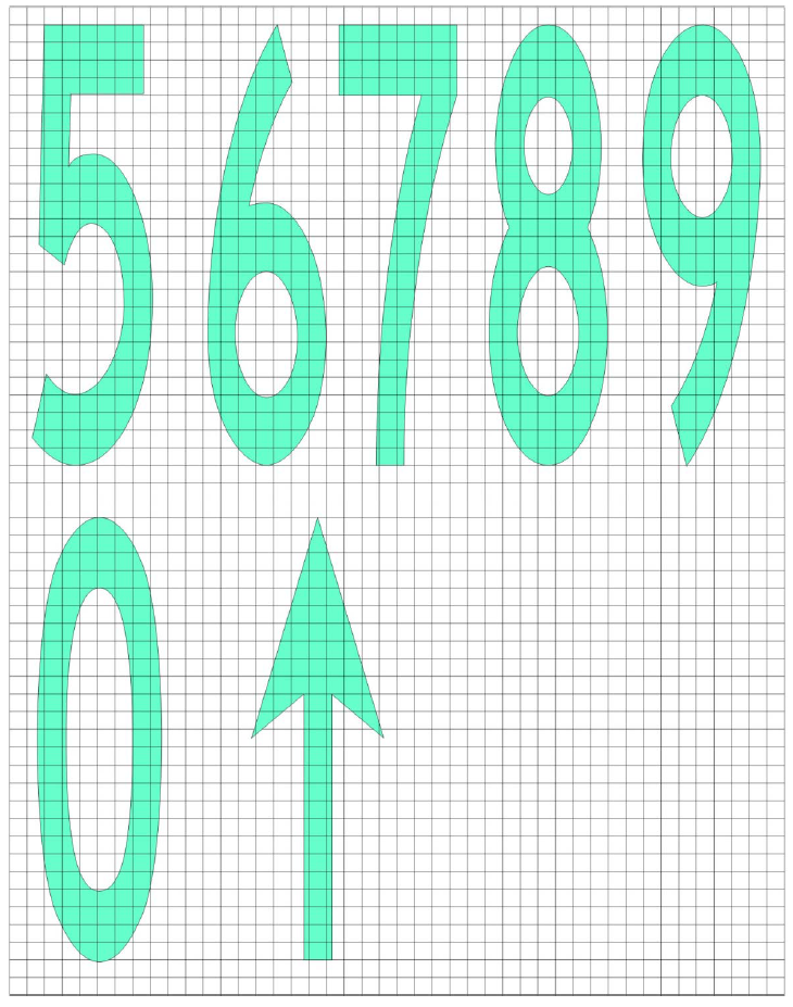
Figure L-10D. Mandatory instruction marking inscription form and proportions
[Issue: ADR-DSN/3]
[Issue: ADR-DSN/4]
[Issue: ADR-DSN/6]
GM1 ADR-DSN.L.610 Information marking
ED Decision 2014/013/R
(a)Applicability: Where operationally required information sign should be supplemented by a marking on the pavement surface.
(b)Location:
(1)An information (location/direction) marking should be displayed prior to and following complex taxiway intersections, and where operational experience has indicated the addition of a taxiway location marking could assist flight crew ground navigation, and on the pavement surface at regular intervals along taxiways of great length.
(2)The information marking should be displayed across the surface of the taxiway or apron where necessary, and positioned so as to be legible from the cockpit of an approaching aircraft.
CHAPTER M — VISUAL AIDS FOR NAVIGATION (LIGHTS)
CS ADR-DSN.M.615 General
ED Decision 2014/013/R
(a)Elevated approach lights:
(1)Elevated approach lights and their supporting structures should be frangible except that, in that portion of the approach lighting system beyond 300 m from the threshold:
(i)where the height of a supporting structure exceeds 12 m, the frangibility requirement should apply to the top 12 m only; and
(ii)where a supporting structure is surrounded by non-frangible objects, only that part of the structure that extends above the surrounding objects should be frangible.
(2)When an approach light fixture or supporting structure is not in itself sufficiently conspicuous, it should be suitably marked.
(b)Elevated lights:
Elevated runway, stopway, and taxiway lights should be frangible. Their height should be sufficiently low to preserve clearance for propellers and for the engine pods of jet aircraft.
(c)Surface lights:
(1)Light fixtures inset in the surface of runways, stopways, taxiways, and aprons should be so designed and fitted as to withstand being run over by the wheels of an aircraft without damage either to the aircraft or to the lights themselves.
(2)The temperature produced by conduction or radiation at the interface between an installed inset light and an aircraft tire should not exceed 160°C during a 10-minute period of exposure.
(d)Light intensity and control:
(1)The intensity of runway lighting should be adequate for the minimum conditions of visibility and ambient light in which use of the runway is intended, and compatible with that of the nearest section of the approach lighting system when provided.
(2)Where a high-intensity lighting system is provided, a suitable intensity control should be incorporated to allow for adjustment of the light intensity to meet the prevailing conditions. Separate intensity controls or other suitable methods should be provided to ensure that the following systems when installed, can be operated at compatible intensities:
(i)approach lighting system;
(ii)runway edge lights;
(iii)runway threshold lights;
(iv)runway end lights;
(v)runway centre line lights;
(vi)runway touchdown zone lights; and
(vii)taxiway centre line lights.
(3)On the perimeter of and within the ellipse defining the main beam in CS ADR-DSN.U.940, the maximum light intensity value should not be greater than three times the minimum light intensity value measured in accordance with CS ADR-DSN.U.940.
On the perimeter of and within the rectangle defining the main beam in CS ADR-DSN.U.940, the maximum light intensity value should not be greater than three times the minimum light intensity value measured in accordance with CS ADR-DSN.U.940.
GM1 ADR-DSN.M.615 General
ED Decision 2014/013/R
(a)Aeronautical ground lights near navigable waters should be taken into consideration to ensure that the lights do not cause confusion to mariners.
(b)In dusk or poor visibility conditions by day, lighting can be more effective than marking. For lights to be effective in such conditions or in poor visibility by night, they should be of adequate intensity. To obtain the required intensity, it should usually be necessary to make the light directional, in which case the arcs over which the light shows should be adequate and so orientated as to meet the operational requirements. The runway lighting system should be considered as a whole, to ensure that the relative light intensities are suitably matched to the same end.
(c)While the lights of an approach lighting system may be of higher intensity than the runway lighting, it is good practice to avoid abrupt changes in intensity as these could give a pilot a false impression that the visibility is changing during approach.
(d)The conspicuity of a light depends on the impression received of contrast between the light and its background. If a light is to be useful to a pilot by day when on approach, it should have an intensity of at least 2 000 or 3 000 cd, and in the case of approach lights an intensity of the order of 20 000 cd is desirable. In conditions of very bright daylight fog it may not be possible to provide lights of sufficient intensity to be effective.
(e)On the other hand, in clear weather on a dark night, an intensity of the order of 100 cd for approach lights and 50 cd for the runway edge lights may be found suitable. Even then, owing to the closer range at which they are viewed, pilots have sometimes complained that the runway edge lights seemed unduly bright.
(f)In fog the amount of light scattered is high. At night this scattered light increases the brightness of the fog over the approach area and runway to the extent that little increase in the visual range of the lights can be obtained by increasing their intensity beyond 2 000 or 3 000 cd. In an endeavour to increase the range at which lights would first be sighted at night, their intensity should not be raised to an extent that a pilot might find excessively dazzling at diminished range.
(g)From the foregoing should be evident the importance of adjusting the intensity of the lights of an aerodrome lighting system according to the prevailing conditions, so as to obtain the best results without excessive dazzle that would disconcert the pilot. The appropriate intensity setting on any particular occasion should depend both on the conditions of background brightness and the visibility.
(h)Assessment on dazzle in the aerodrome vicinity:
(1)Human vision is a complex mechanism using both eye and brain. Even though this mechanism is quite handled for eye, there is still a lack of knowledge on the interpretation of it by the brain. Thus, vision varies from one human being to another.
(2)The field of view is defined by the area perceived by eyes. The perception of details is based on the luminance ratio between elements of the scene, taking into account spatial distribution. Luminance and contrast are key elements of vision mechanism.
(3)Four sectors can be identified in the field of view (FOV):
(i)sensation field, corresponding to the absolute boundaries of FOV; it opens up to approximately 90° on each side of the eye direction;
(ii)visibility field, which is narrower and enables the perception of an object; it opens up to 60°;
(iii)conspicuity field, which enables the recognition, it opens up to 30°;
(iv)working conspicuity field, which is further tightly centred on the eye direction (1° to 2°); it enables the identification and is the working area of the vision.
It is reminded that the retina is composed in its centre by cone cells (that see colours and details) and at the periphery by rod cells (that perceive movements and change of state).
(i)A safety assessment is conducted in order to identify situations where the risk of dazzling becomes unacceptable. Thus, it is noted that dazzle represents such a risk in the following situations:
(1)during approach, especially after the aircraft has descended below the decision height: the pilot should not lose any visual cue;
(2)at touchdown the pilot should not be surprised by a flash;
(3)during rolling (landing or take-off), the pilot should be able to perceive his environment and detect any deviation from the centre line: the pilot should not lose any visual cue.
(4)Thus:
(i)prejudicial dazzle due to veiling luminance should not occur during approach (slightly before the decision height) and rolling; and
(ii)surprise effect should not occur at touchdown.
(j)Regarding air traffic controllers, it has been considered that dazzle induced by veiling effect should not reduce the visual perception of aircraft operations on, and close to the runway.
(k)The elements here above can be applied to solar panels. The following assumptions can be made:
(1)solar panels are inclined so as to efficiently capture the sunlight, conducting to a range of cross section surfaces;
(2)the maximum acceptable luminance value has been fixed to 20 000 cd/m2; and
(3)the surfaces varied from 100 m2 to several hectares.
(l)It is assumed that the aircraft maintains precisely its trajectory whereas in reality the approach is conducted into a conical envelop around the expected trajectory.
CS ADR-DSN.M.620 Aeronautical beacons
ED Decision 2014/013/R
(a)General
(1)When operationally necessary an aerodrome beacon or identification beacon should be provided at each aerodrome intended for use at night.
(2)The operational requirement should be determined having regard to the requirements of the air traffic using the aerodrome, the conspicuity of the aerodrome features in relation to its surroundings, and the installation of other visual and non-visual aids useful in locating the aerodrome.
(b)Aerodrome beacon
(1)Applicability
An aerodrome beacon should be provided at an aerodrome intended for use at night if aircraft navigate predominantly by visual means and one or more of the following conditions exist:
(i)reduced visibilities are frequent; or
(ii)it is difficult to locate the aerodrome from the air due to surrounding lights or terrain.
(2)Location
(i)The aerodrome beacon should be located on or adjacent to the aerodrome in an area of low ambient background lighting.
(ii)The location of the beacon should be such that the beacon is not shielded by objects in significant directions and does not dazzle a pilot approaching to land.
(3)Characteristics
(i)The aerodrome beacon should show either coloured flashes alternating with white flashes or white flashes only.
(ii)The frequency of total flashes should be from 20 to 30 per minute.
(iii)The light from the beacon should show at all angles of azimuth. The vertical light distribution should extend upwards from an elevation of not more than 1° to an elevation sufficient to provide guidance at the maximum elevation at which the beacon is intended to be used, and the effective intensity of the flash should be not less than 2 000 cd.
(iv)At locations where a high ambient background lighting level cannot be avoided, the effective intensity of the flash should be required to be increased by a factor up to a value of 10.
(c)Identification beacon
(1)Applicability
An identification beacon should be provided at an aerodrome which is intended for use at night and cannot be easily identified from the air by other means.
(2)Location
(i)The identification beacon should be located on the aerodrome in an area of low ambient background lighting.
(ii)The location of the beacon should be such that the beacon is not shielded by objects in significant directions and does not dazzle a pilot approaching to land.
(3)Characteristics
(i)An identification beacon at a land aerodrome should show at all angles of azimuth. The vertical light distribution should extend upwards from an elevation of not more than 1° to an elevation sufficient to provide guidance at the maximum elevation at which the beacon is intended to be used, and the effective intensity of the flash should be not less than 2 000 cd.
(ii)At locations where a high ambient background lighting level cannot be avoided, the effective intensity of the flash should be required to be increased by a factor up to a value of 10.
(iii)An identification beacon should show flashing-green.
(iv)The identification characters should be transmitted in the International Morse Code.
(v)The speed of transmission should be between six and eight words per minute, the corresponding range of duration of the Morse dots being from 0.15 to 0.2 seconds per dot.
GM1 ADR-DSN.M.620 Aeronautical beacons
ED Decision 2014/013/R
intentionally left blank
CS ADR-DSN.M.625 Approach lighting systems
ED Decision 2016/027/R
(a)The safety objective of the approach lighting system is to provide alignment and roll guidance, and limited distance-to-go information to enable safe approach to a runway.
(b)Non-instrument runway
Applicability: Where physically practicable, a simple approach lighting system as specified in CS ADR-DSN.M.626 should be provided to serve a non-instrument runway where the code number is 3 or 4, and intended for use at night, except when the runway is used only in conditions of good visibility, and sufficient guidance is provided by other visual aids.
(c)Non-precision approach runway
Applicability: Where physically practicable, a simple approach lighting system specified in CS ADR-DSN.M.626 should be provided to serve a non-precision approach runway, except when the runway is used only in conditions of good visibility or sufficient guidance is provided by other visual aids.
(d)Precision approach runway Category I
Applicability: Where physically practicable, a precision approach Category I lighting system as specified in CS ADR-DSN.M.630 should be provided to serve a precision approach runway Category I.
(e)Precision approach runway Categories II and III
Applicability: A precision approach Category II and III lighting system as specified in CS ADR-DSN.M.635 should be provided to serve a precision approach runway Category II or III.
[Issue: ADR-DSN/3]
GM1 ADR-DSN.M.625 Approach lighting systems
ED Decision 2017/021/R
(a)Types and characteristics
(1)The approach lighting patterns that have been generally adopted are shown in Figures M-1 and M-2. A diagram of the inner 300 m of the precision approach Category II and III lighting system is shown in Figures M-3A and M-3B.
(2)The approach lighting configuration is to be provided irrespective of the location of the threshold, i.e. whether the threshold is at the extremity of the runway or displaced from the runway extremity. In both cases, the approach lighting system should extend up to the threshold. However, in the case of a displaced threshold, inset lights are used from the runway extremity up to the threshold to obtain the specified configuration. These inset lights are designed to satisfy the structural requirements specified in CS ADR.DSN.M.615(d)(1).The characteristics of these inset lights should be in accordance with the specifications in CS ADR-DSN.U.940, Figures U-5 or U-6, as appropriate and the chromaticity should be in accordance with the specifications in CS ADR-DSN.U.930 and Figure U-1A or U-1B, as appropriate.
(3)Examples of flight path envelopes used in designing the lighting are shown in Figure GM-M-2.
(b)Horizontal installation tolerances:
(1)The dimensional tolerances are shown in Figure M-1 and M-2.
(2)The centre line of an approach lighting system should be as coincident as possible with the extended centre line of the runway with a maximum tolerance of ±15′.
(3)The longitudinal spacing of the centre line lights should be such that one light (or group of lights) is located in the centre of each crossbar, and the intervening centre line lights are spaced as evenly as practicable, between two crossbars or a crossbar and a threshold.
(4)The crossbars and barrettes should be at right angles to the centre line of the approach lighting system with a tolerance of ±30′ if the pattern in Figure M-2(A) is adopted or ± 2° if Figure M-2(B) is adopted.
(5)When a crossbar has to be displaced from its standard position, any adjacent crossbar should where possible, be displaced by appropriate amounts in order to reduce the differences in the crossbar spacing.
(6)When a crossbar in the system shown in Figure M-2(A) is displaced from its standard position, its overall length should be adjusted so that it remains one-twentieth of the actual distance of the crossbar from the point of origin. It is not necessary, however, to adjust the standard 2.7 m spacing between the crossbar lights but the crossbars should be kept symmetrical about the centre line of the approach lighting.
(c)Vertical installation tolerances:
(1)The ideal arrangement is to mount all the approach lights in the horizontal plane passing through the threshold as shown in Figure GM-M-1, and this should be the general aim as far as local conditions permit. However, buildings, trees, etc. should not obscure the lights from the view of a pilot who is assumed to be 1° below the electronic glide path in the vicinity of the outer marker.
(2)Within a stopway or clearway, and within 150 m of the end of a runway, the lights should be mounted as near to the ground as local conditions permit in order to minimise risk of damage to aeroplanes in the event of an overrun or undershoot. Beyond the stopway and clearway, it is not so necessary for the lights to be mounted close to the ground, and, therefore, undulations in the ground contours can be compensated for by mounting the lights on poles of appropriate height.
(3)It is desirable that the lights be mounted so that as far as possible, no object within a distance of 60 m on each side of the centre line protrudes through the plane of the approach lighting system. Where a tall object exists within 60 m of the centre line and within 1 350 m from the threshold for a precision approach lighting system, or 900 m for a simple approach lighting system, it may be advisable to install the lights so that the plane of the outer half of the pattern clears the top of the object.
(4)In order to avoid giving a misleading impression of the plane of the ground, the lights should not be mounted below a gradient of 1 in 66 downwards from the threshold to a point 300 m out, and below a gradient of 1 in 40 beyond the 300 m point. For a precision approach Category II and III lighting system, more stringent criteria may be necessary, e.g. negative slopes not permitted within 450 m of the threshold.
(i)Centre line. The gradients of the centre line in any section (including a stopway or clearway) should be as small as practicable, and the changes in gradients should be as few and small as can be arranged, and should not exceed 1 in 60. Experience has shown that as one proceeds outwards from the runway, rising gradients in any section of up to 1 in 66, and falling gradients of down to 1 in 40, are acceptable.
(ii)Crossbars. The crossbar lights should be so arranged as to lie on a straight line passing through the associated centre line lights, and wherever possible, this line should be horizontal. It is permissible, however, to mount the lights on a transverse gradient not more than 1 in 80 if this enables crossbar lights within a stopway or clearway to be mounted nearer to the ground on sites where there is a cross-fall.
(5)When the barrette is composed of lights approximating to point sources, a spacing of 1.5 m between adjacent lights in the barrette has been found satisfactory.
(6)At locations where identification of the simple approach lighting system is difficult at night due to surrounding lights, sequence flashing lights installed in the outer portion of the system may resolve this problem.
(d)Clearance of obstacles:
(1)An area, hereinafter referred to as the light plane, has been established for obstacle clearance purposes, and all lights of the system are in this plane. This plane is rectangular in shape and symmetrically located about the approach lighting system’s centre line. It starts at the threshold and extends 60 m beyond the approach end of the system, and is 120 m wide.
(2)No objects are permitted to exist within the boundaries of the light plane which are higher than the light plane except as designated herein. All roads and highways are considered as obstacles extending 4.8 m above the crown of the road, except aerodrome service roads where all vehicular traffic is under control of the aerodrome operator and coordinated with the aerodrome air traffic control. Railroads, regardless of the amount of traffic, are considered as obstacles extending 5.4 m above the top of the rails.
(3)It is recognised that some components of electronic landing aids systems, such as reflectors, antennas, monitors, etc. should be installed above the light plane. Every effort should be made to relocate such components outside the boundaries of the light plane. In the case of reflectors and monitors, this can be done in many instances.
(4)Where an ILS localiser is installed within the light plane boundaries, it is recognised that the localiser, or screen if used, should extend above the light plane. In such cases, the height of these structures should be held to a minimum and they should be located as far from the threshold as possible. In general, the rule regarding permissible heights is 15 cm for each 30 m the structure is located from the threshold. As an example, if the localiser is located 300 m from the threshold, the screen should be permitted to extend above the plane of the approach lighting system by 10 × 15 = 150 cm maximum but preferably should be kept as low as possible, consistent with proper operation of the ILS.
(5)In locating an MLS azimuth antenna the guidance contained in ICAO Annex 10, Volume I, Attachment G, should be followed. This material which also provides guidance on collocating an MLS azimuth antenna with an ILS localiser antenna, suggests that the MLS azimuth antenna may be sited within the light plane boundaries where it is not possible or practical to locate it beyond the outer end of the approach lighting for the opposite direction of approach. If the MLS azimuth antenna is located on the extended centre line of the runway, it should be as far as possible from the closest light position to the MLS azimuth antenna in the direction of the runway end. Furthermore, the MLS azimuth antenna phase centre should be at least 0.3 m above the light centre of the light position closest to the MLS azimuth antenna in the direction of the runway end. (This could be relaxed to 0.15 m if the site is otherwise free of significant multipath problems.)
(6)Compliance with this requirement which is intended to ensure that the MLS signal quality is not affected by the approach lighting system, could result in the partial obstruction of the lighting system by the MLS azimuth antenna. To ensure that the resulting obstruction does not degrade visual guidance beyond an acceptable level, the MLS azimuth antenna should not be located closer to the runway end than 300 m and the preferred location is 25 m beyond the 300 m crossbar (this would place the antenna 5 m behind the light position 330 m from the runway end). Where an MLS azimuth antenna is so located, a central part of the 300 m crossbar of the approach lighting system would alone be partially obstructed. Nevertheless, it is important to ensure that the unobstructed lights of the crossbar remain serviceable all the time.
(7)Objects existing within the boundaries of the light plane, requiring the light plane to be raised in order to meet the criteria contained herein, should be removed, lowered, or relocated where this can be accomplished more economically than raising the light plane.
(8)In some instances objects may exist which cannot be removed, lowered, or relocated economically. These objects may be located so close to the threshold that they cannot be cleared by the 2 % slope. Where such conditions exist and no alternative is possible, the 2 % slope may be exceeded or a ‘stair step’ resorted to in order to keep the approach lights above the objects. Such ‘step’ or increased gradients should be resorted to only when it is impracticable to follow standard slope criteria, and they should be held to the absolute minimum. Under this criterion no negative slope is permitted in the outermost portion of the system.
(e)Consideration of the effects of reduced lengths:
(1)The need for an adequate approach lighting system to support precision approaches where the pilot is required to acquire visual references prior to landing, cannot be stressed too strongly. The safety and regularity of such operations is dependent on this visual acquisition. The height above runway threshold at which the pilot decides there are sufficient visual cues to continue the precision approach and land, should vary, depending on the type of approach being conducted and other factors such as meteorological conditions, ground and airborne equipment, etc. The required length of approach lighting system which should support all the variations of such approaches is 900 m, and this should always be provided whenever possible.
(2)However, there are some runway locations where it is impossible to provide the 900 m length of approach lighting system to support precision approaches.
(3)In such cases, every effort should be made to provide as much approach lighting system as possible. Restrictions on operations could be imposed on runways equipped with reduced lengths of approach lighting. There are many factors which determine at what height the pilot should have decided to continue the approach to land or execute a missed approach. It should be understood that the pilot does not make an instantaneous judgement upon reaching a specified height. The actual decision to continue the approach and landing sequence is an accumulative process which is only concluded at the specified height. Unless lights are available prior to reaching the decision point, the visual assessment process is impaired and the likelihood of missed approaches should increase substantially. There are many operational considerations which should be taken into account in deciding if any restrictions are necessary to any precision approach and these are detailed in ICAO Annex 6.
(f)For non-precision approach runways it is advisable to give consideration to the installation of a precision approach Category I lighting system or to the addition of a runway lead-in lighting system.
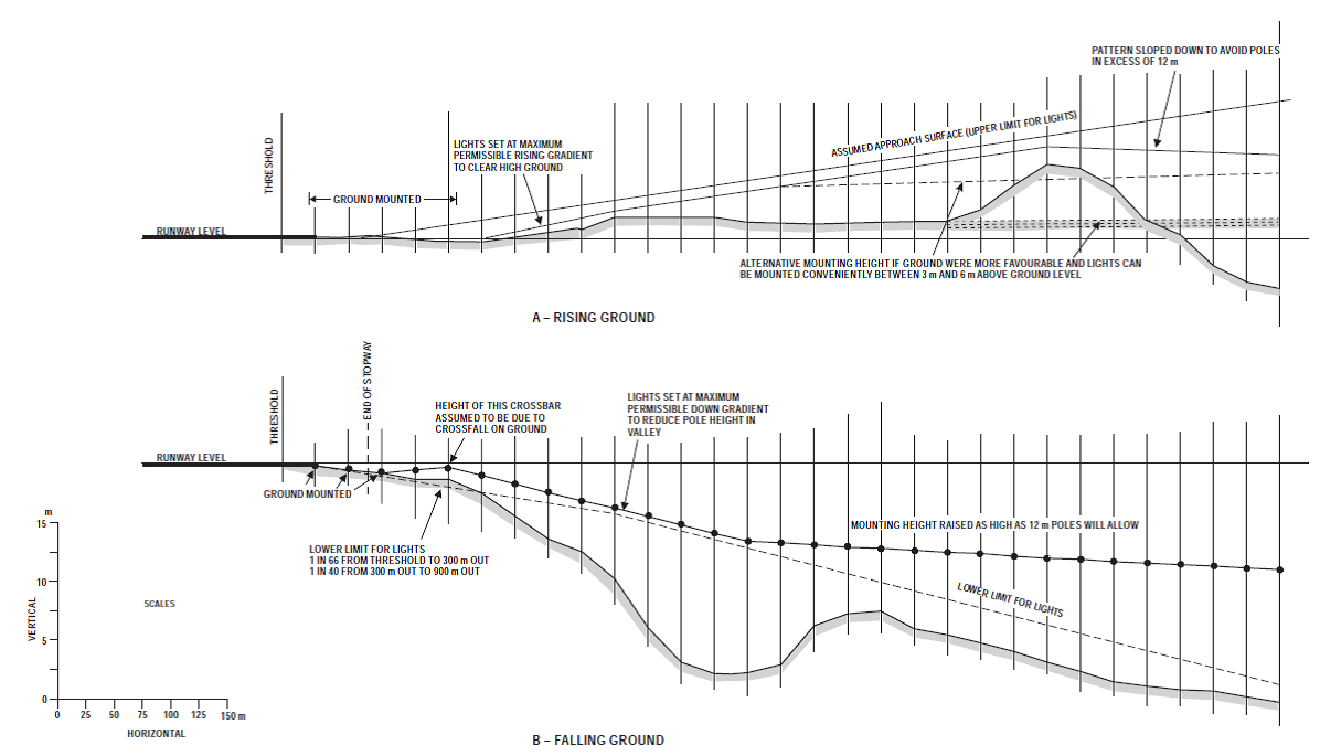
Figure GM-M-1. Vertical installation tolerances
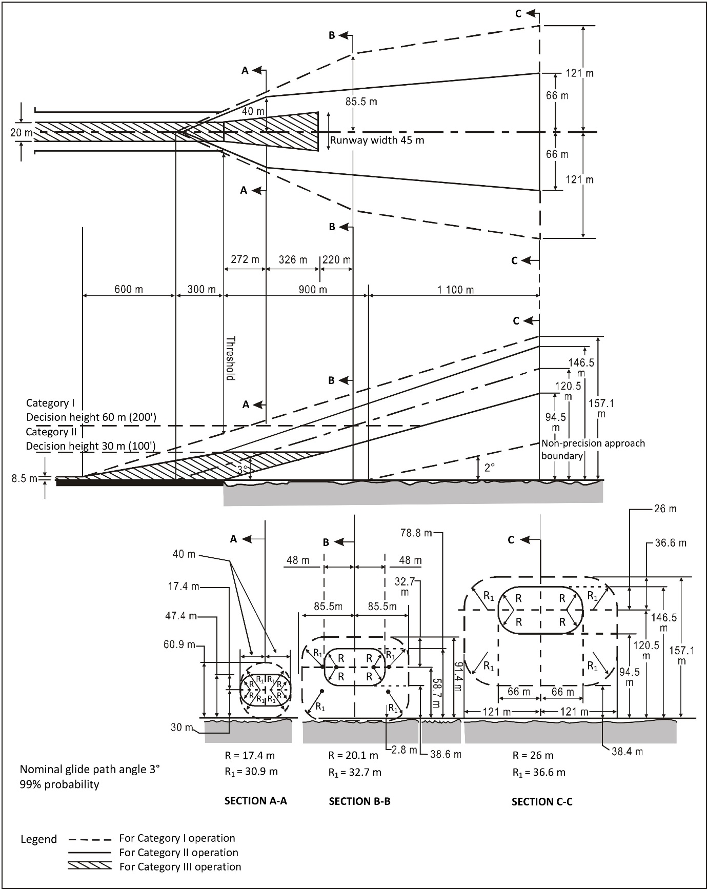
Figure GM-M-2. Flight path envelope examples for lighting design for Category I, II and III operations — Centre line lights
[Issue: ADR-DSN/3]
[Issue: ADR-DSN/4]
CS ADR-DSN.M.626 Simple approach lighting systems
ED Decision 2021/004/R
(a)Location and composition:
(1)A simple approach lighting system should consist of a row of lights on the extended centre line of the runway extending, whenever possible, over a distance of not less than 420 m from the threshold with a row of lights forming a crossbar 18 m or 30 m in length at a distance of 300 m from the threshold (see Figure M-1).
(2)The certification specifications provide for the basic characteristics for simple approach lighting systems. For certain aspects of these systems, some latitude is permitted; for example, in the spacing between centre line lights and crossbar.
(b)Crossbar lights:
(1)The lights forming the crossbar should be as close as practicable in a horizontal straight line at right angles to, and bisected by, the line of the centre line lights.
(2)The lights of the crossbar should be spaced so as to produce a linear effect, except that, when a crossbar of 30 m is used, gaps may be left on each side of the centre line. These gaps should be kept to a minimum to meet local requirements, and each should not exceed 6 m.
(3)Spacing for the crossbar lights between 1 m and 4 m are in use. Gaps on each side of the centre line may improve directional guidance when approaches are made with a lateral error, and facilitate the movement of rescue and firefighting vehicles.
(c)Centre line lights:
(1)The lights forming the centre line should be placed at longitudinal intervals of 60 m, except that when it is desired to improve the guidance, an interval of 30 m may be used.
(2)The innermost light should be located either 60 m or 30 m from the threshold, depending on the longitudinal interval selected for the centre line lights. If it is not physically possible to provide a centre line extending for a distance of 420 m from the threshold, it should be extended to 300 m so as to include the crossbar. If this is not possible, the centre line lights should be extended as far as practicable, and each centre line light should then consist of a barrette at least 3 m in length. Subject to the approach system having a crossbar at 300 m from the threshold, an additional crossbar may be provided at 150 m from the threshold.
(3)The system should lie as nearly as practicable in the horizontal plane passing through the threshold, provided that:
(i)no object other than an ILS or MLS azimuth antenna should protrude through the plane of the approach lights within a distance of 60 m from the centre line of the system; and
(ii)no light other than a light located within the central part of a crossbar or a centre line barrette, excluding their extremities, should be screened from an approaching aircraft.
Any ILS or MLS azimuth antenna protruding through the plane of the lights should be treated as an obstacle, and marked and lighted accordingly as specified in the requirements for obstacle marking and lighting.
(d)Characteristics:
(1)The lights of a simple approach lighting system should be fixed lights and the colour of the lights should be such as to ensure that the system is readily distinguishable from other aeronautical ground lights, and from extraneous lighting if present, but should be preferably fixed lights showing variable white. Each centre line light should consist of either:
(i)a single source; or
(ii)a barrette at least 3 m in length.
(e)Barrettes of 4 m in length should be so designed if it is anticipated that the simple approach lighting system should be developed into a precision approach lighting system.
(f)Where provided for a non-instrument runway, the lights should show at all angles in azimuth necessary to a pilot on base leg and final approach. The intensity of the lights should be adequate for all conditions of visibility and ambient light for which the system has been provided.
(g)Where provided for a non-precision approach runway, the lights should show at all angles in azimuth necessary to the pilot of an aircraft which on final approach does not deviate by an abnormal amount from the path defined by the non-visual aid. The lights should be designed to provide guidance during both day and night in the most adverse conditions of visibility and ambient light for which it is intended that the system should remain usable.
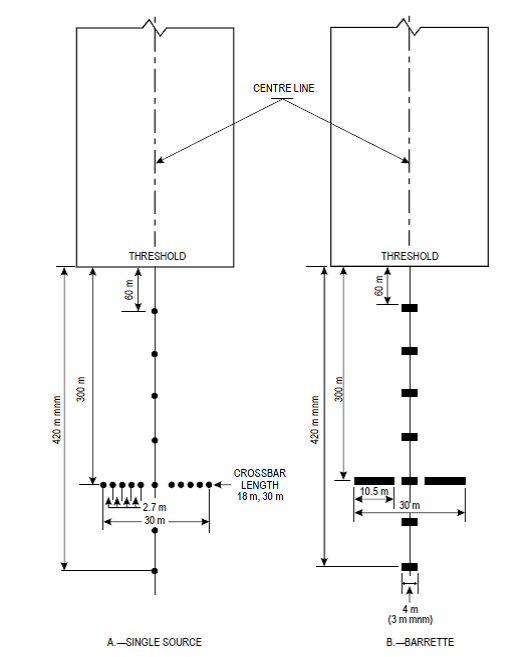
Figure M-1. Simple approach lighting systems
[Issue: ADR-DSN/3]
[Issue: ADR-DSN/5]
GM1 ADR-DSN.M.626 Simple approach lighting systems
ED Decision 2014/013/R
intentionally left blank
CS ADR-DSN.M.630 Precision approach Category I lighting system
ED Decision 2021/004/R
(a)The safety objective of the approach lighting system is to provide alignment and roll guidance, and limited distance-to-go information to enable safe approach to a runway.
(b)Location and composition
(1)General: A precision approach Category I lighting system should consist of a row of lights on the extended centre line of the runway extending wherever possible, over a distance of 900 m from the runway threshold with a row of lights forming a crossbar 30 m in length at a distance of 300 m from the runway threshold (see Figure M-2).
(2)Crossbar lights: The lights forming the crossbar should be as close as practicable in a horizontal straight line at right angles to, and bisected by, the line of the centre line lights. The lights of the crossbar should be spaced so as to produce a linear effect, except that gaps may be left on each side of the centre line. These gaps should be kept to a minimum to meet local requirements and each should not exceed 6 m.
(3)Centre line lights: The lights forming the centre line should be placed at longitudinal intervals of 30 m with the innermost light located 30 m from the threshold.
(4)The system should lie as nearly as practicable in the horizontal plane passing through the threshold, provided that:
(i)no object other than an ILS or MLS azimuth antenna should protrude through the plane of the approach lights within a distance of 60 m from the centre line of the system; and
(ii)no light other than a light located within the central part of a crossbar or a centre line barrette (not their extremities) should be screened from an approaching aircraft.
(iii)Any ILS or MLS azimuth antenna protruding through the plane of the lights should be treated as an obstacle and marked and lighted accordingly.
(c)Characteristics:
(1)The centre line and crossbar lights of a precision approach Category I lighting system should be fixed lights showing variable white. Each centre line light position should consist of either:
(i)a single light source in the innermost 300 m of the centre line, two light sources in the central 300 m of the centre line, and three light sources in the outer 300 m of the centre line to provide distance information; or
(ii)a barrette.
(2)Where the serviceability level of the approach lights specified as a maintenance objective in ADR.OPS.C.015 can be demonstrated, each centre line light position should consist of either:
(i)a single light source; or
(ii)a barrette.
When barrettes are composed of lights approximating to point sources, the lights should be uniformly spaced at intervals of not more than 1.5 m. The barrettes should be at least 4 m in length.
(3)If the centre line consists of lights as described in paragraph (c)(1)(i) or (c)(2)(i) above, additional crossbars of lights to the crossbar provided at 300 m from the threshold should be provided at 150 m, 450 m, 600 m and 750 m from the threshold. The lights forming each crossbar should be as nearly as practicable in a horizontal straight line at right angles to, and bisected by, the line of the centre line lights. The lights should be spaced so as to produce a linear effect, except that gaps may be left on each side of the centre line. These gaps should be kept to a minimum to meet local requirements and each should not exceed 6 m.
(4)Where the additional crossbars are incorporated in the system, the outer ends of the crossbars should lie on two straight lines that either are parallel to the line of the centre line lights or converge to meet the runway centre line 300 m upwind from threshold.
(5)The characteristics of lights should be in accordance with the specifications in CS ADR-DSN.U.940, Figure U-5. The chromaticity of lights should be in accordance with the specifications in CS ADR-DSN.U.930 and Figure U-1A or U-1B, as appropriate.
(6)If the centre line consists of barrettes as described in paragraph (c)(1)(ii) or (c)(2)(ii) above, each barrette should be supplemented by a flashing light, except where such lighting is considered unnecessary taking into account the characteristics of the system, and the nature of the meteorological conditions.
(7)Each flashing light, as described in paragraph (c)(6), should be flashed twice a second in sequence, beginning with the outermost light and progressing toward the threshold to the innermost light of the system. The design of the electrical circuit should be such that these lights can be operated independently of the other lights of the approach lighting system.
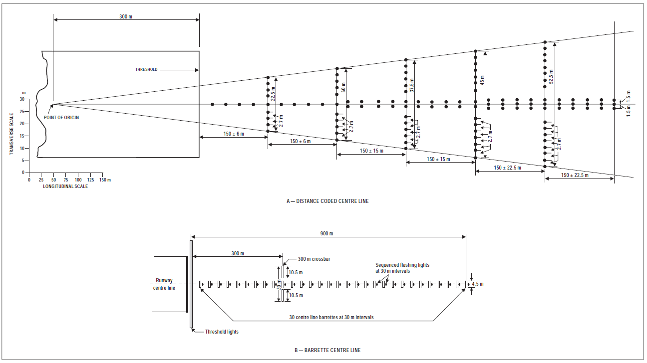
Figure M-2. Precision approach Category I lighting systems
[Issue: ADR-DSN/3]
[Issue: ADR-DSN/4]
[Issue: ADR-DSN/5]
GM1 ADR-DSN.M.630 Precision approach Category I lighting system
ED Decision 2017/021/R
(a)The installation of an approach lighting system of less than 900 m in length may result in operational limitations on the use of the runway.
(b)Spacings for the crossbar lights between 1 m and 4 m are in use. Gaps on each side of the centre line may improve directional guidance when approaches are made with a lateral error, and facilitate the movement of rescue and firefighting vehicles.
(c)The flashing light system provides a long-distance information about the location and orientation of an active runway to the approaching pilots. Particularly in the surrounding of cities with urban lighting of streets, places and buildings, the flashing light system allows a clear identification of the approach by the flight crew. To prevent glare at night and have clear visibility, the high-intensity flashing light should be provided with an appropriate intensity control.
[Issue: ADR-DSN/3]
[Issue: ADR-DSN/4]
CS ADR-DSN.M.635 Precision approach Category II and III lighting system
ED Decision 2021/004/R
(a)Location and composition:
(1)The approach lighting system should consist of a row of lights on the extended centre line of the runway, extending, wherever possible, over a distance of 900 m from the runway threshold. In addition, the system should have two side rows of lights, extending 270 m from the threshold, and two crossbars, one at 150 m and one at 300 m from the threshold, all as shown in Figure M-3A. Where the serviceability level of the approach lights specified as maintenance objectives in ADR.OPS.C.015 can be demonstrated, the system may have two side rows of lights extending 240 m from the threshold, and two crossbars, one at 150 m, and one at 300 m from the threshold, all as shown in Figure M-3B.
(2)The lights forming the centre line should be placed at longitudinal intervals of 30 m with the innermost lights located 30 m from the threshold.
(3)The lights forming the side rows should be placed on each side of the centre line, at a longitudinal spacing equal to that of the centre line lights and with the first light located 30 m from the threshold. Where the serviceability level of the approach lights specified as maintenance objectives can be demonstrated, lights forming the side rows may be placed on each side of the centre line, at a longitudinal spacing of 60 m with the first light located 60 m from the threshold. The lateral spacing (or gauge) between the innermost lights of the side rows should be not less than 18 m nor more than 22.5 m, and preferably 18 m, but in any event should be equal to that of the touchdown zone lights.
(4)The crossbar provided at 150 m from the threshold should fill in the gaps between the centre line and side row lights.
(5)The crossbar provided at 300 m from the threshold should extend on both sides of the centre line lights to a distance of 15 m from the centre line.
(6)If the centre line beyond a distance of 300 m from the threshold consists of lights as described in paragraphs (b)(2)(ii) and (b)(3)(ii) below, additional crossbars of lights should be provided at 450 m, 600 m and 750 m from the threshold. Where such additional crossbars are incorporated in the system, the outer ends of these crossbars should lie on two straight lines that either are parallel to the centre line or converge to meet the runway centre line 300 m from the threshold.
(7)The system should lie as nearly as practicable in the horizontal plane passing through the threshold, provided that:
(i)no object other than an ILS or MLS azimuth antenna should protrude through the plane of the approach lights within a distance of 60 m from the centre line of the system; and
(ii)no light other than a light located within the central part of a crossbar or a centre line barrette (not their extremities) should be screened from an approaching aircraft.
(iii)Any ILS or MLS azimuth antenna protruding through the plane of the lights should be treated as an obstacle and marked and lighted accordingly.
(b)Characteristics:
(1)The centre line of a precision approach Category II and III lighting system for the first 300 m from the threshold should consist of barrettes showing variable white, except that where the threshold is displaced 300 m or more, the centre line may consist of single light sources showing variable white. Where the serviceability level of the approach lights specified in ADR.OPS.C.015 can be demonstrated, the centre line of a precision approach Category II and III lighting system for the first 300 m from the threshold may consist of:
(i)barrettes where the centre line beyond 300 m from the threshold consists of barrettes as described in paragraph (b)(3)(i) below; or
(ii)alternate single light sources and barrettes, where the centre line beyond 300 m from the threshold consists of single light sources as described in paragraph (b)(3)(ii) below, with the innermost single light source located 30 m and the innermost barrette located 60 m from the threshold; or
(iii)single light sources where the threshold is displaced 300 m or more;
all of which should show variable white.
(2)Beyond 300 m from the threshold each centre line light position should consist of either:
(i)a barrette as used on the inner 300 m; or
(ii)two light sources in the central 300 m of the centre line, and three light sources in the outer 300 m of the centre line;
all of which should show variable white.
(3)Where the serviceability level of the approach lights in ADR.OPS.C.015 as maintenance objectives can be demonstrated beyond 300 m from the threshold, each centre line light position may consist of either:
(i)a barrette; or
(ii)a single light source;
all of which should show variable white.
(4)The barrettes should be at least 4 m in length. When barrettes are composed of lights approximating to point sources, the lights should be uniformly spaced at intervals of not more than 1.5 m.
(5)If the centre line beyond 300 m from the threshold consists of barrettes as described in paragraphs (b)(2)(i) and (b)(3)(i), each barrette beyond 300 m should be supplemented by a flashing light, except where such lighting is considered unnecessary taking into account the characteristics of the system and the nature of the meteorological conditions.
(6)Each flashing light should be flashed twice a second in sequence, beginning with the outermost light and progressing toward the threshold to the innermost light of the system. The design of the electrical circuit should be such that these lights can be operated independently of the other lights of the approach lighting system.
(7)The side row should consist of barrettes showing red. The length of a side row barrette and the spacing of its lights should be equal to those of the touchdown zone light barrettes.
(8)The lights forming the crossbars should be fixed lights showing variable white. The lights should be uniformly spaced at intervals of not more than 2.7 m.
(9)The intensity of the red lights should be compatible with the intensity of the white lights.
(10)The characteristics of lights should be in accordance with the specifications in CS ADR-DSN.U.940, Figures U-5 or U-6, as appropriate.
(11)The chromaticity of lights should be in accordance with the specifications in CS ADR-DSN.U.930 and Figure U-1A or U-1B, as appropriate.
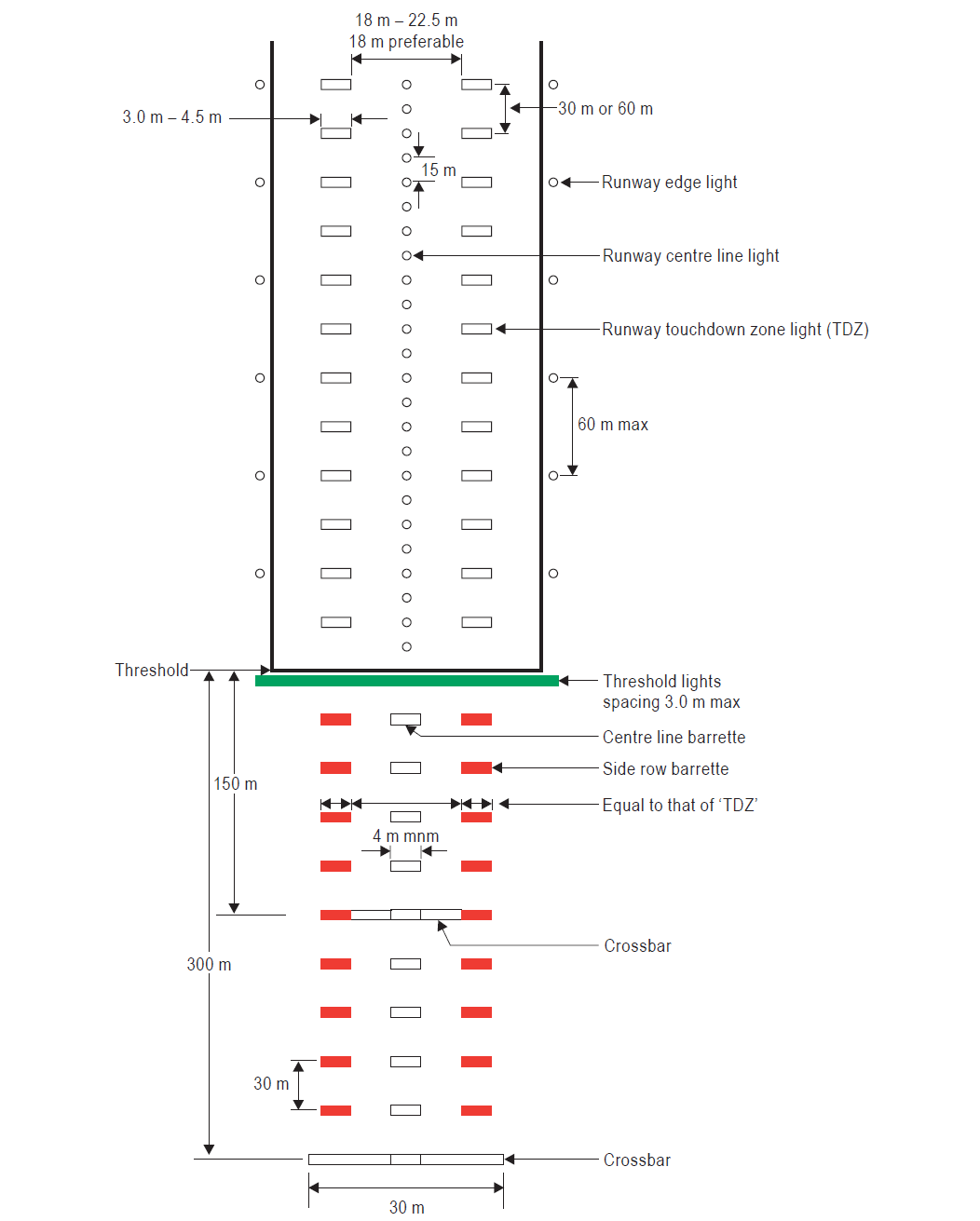
Figure M-3A. Inner 300 m approach and runway lighting for precision approach runways, Categories II and III
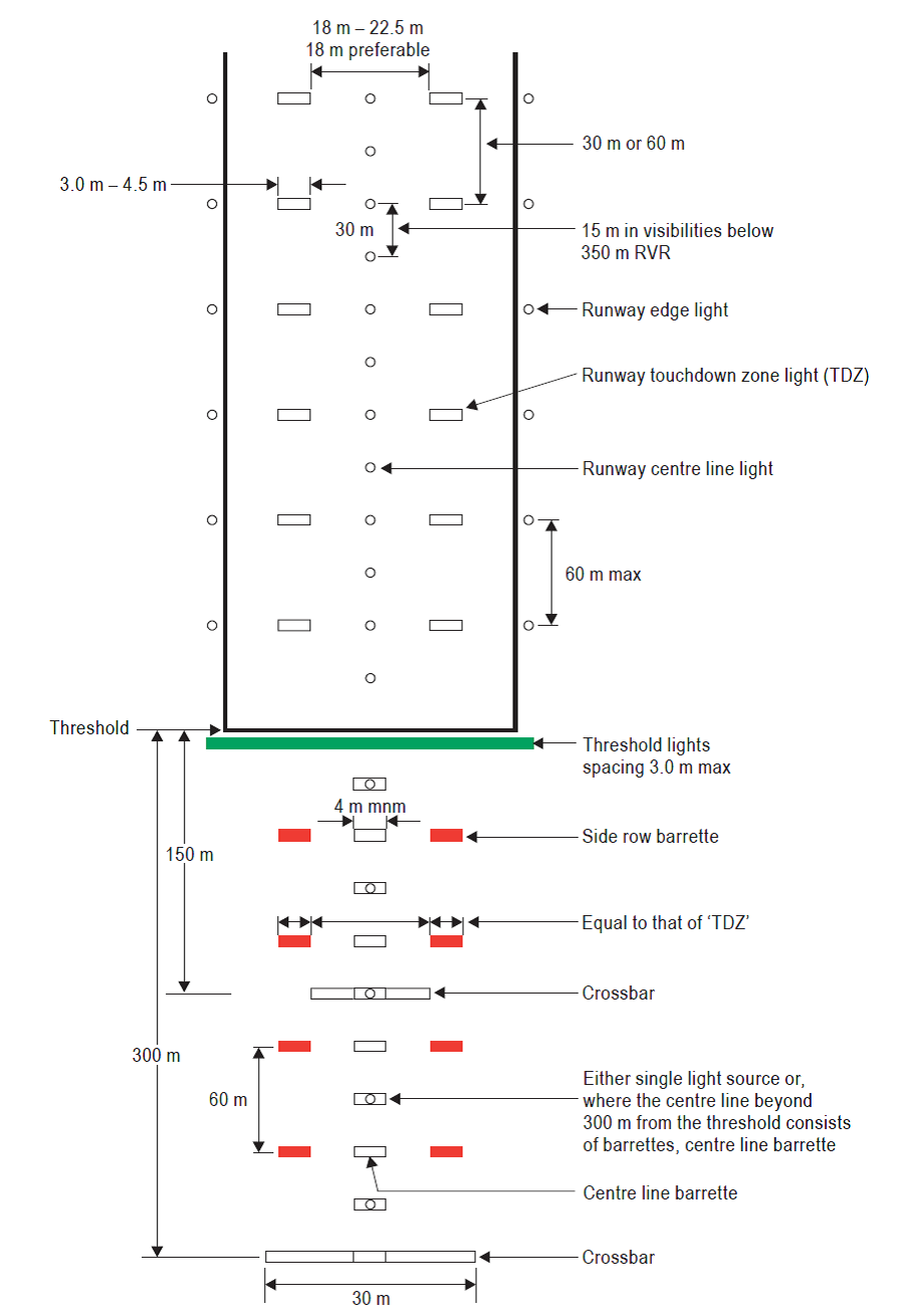
Figure M-3B. Inner 300 m approach and runway lighting for precision approach runways, Categories II and III, where the serviceability levels of the lights specified as maintenance objectives in ADR.OPS.C.015(b)(1) to (3) can be demonstrated.
[Issue: ADR-DSN/3]
[Issue: ADR-DSN/4]
[Issue: ADR-DSN/5]
GM1 ADR-DSN.M.635 Precision approach Category II and III lighting system
ED Decision 2016/027/R
The length of 900 m is based on providing guidance for operations under Category I, II and III conditions. Reduced lengths may support Category II and III operations but may impose limitations on Category I operations. Additional guidance is given in ICAO Annex 14, Attachment A, Section 11.
[Issue: ADR-DSN/3]
CS ADR-DSN.M.640 Visual approach slope indicator systems
ED Decision 2014/013/R
The safety objective of visual approach slope indicators is to provide information on the approach angle necessary to maintain a safe height over obstacles and threshold.
(a)A visual approach slope indicator system should be provided to serve the approach to a runway where one or more of the following conditions exist:
(1)the runway is used by turbojet or other aeroplanes with similar approach guidance requirements;
(2)the pilot of any type of aeroplane may have difficulty in judging the approach due to:
(i)inadequate visual guidance such as is experienced during an approach over water or featureless terrain by day or in the absence of sufficient extraneous lights in the approach area by night; or
(ii)misleading information such as is produced by deceptive surrounding terrain or runway slopes.
(3)the presence of objects in the approach area may involve serious hazard if an aeroplane descends below the normal approach path, particularly if there are no non-visual or other visual aids to give warning of such objects;
(4)physical conditions at either end of the runway present a serious hazard in the event of an aeroplane undershooting or overrunning the runway; and
(5)terrain or prevalent meteorological conditions are such that the aeroplane may be subjected to unusual turbulence during approach.
(b)The standard visual approach slope indicator systems should consist of PAPI and APAPI systems conforming to the specifications, as prescribed in CS ADR-DSN.M.645 to CS ADR-DSN.M.655.
(c)PAPI should be provided where the code number is 3 or 4 when one or more of the conditions specified in paragraph (a) above exist.
(d)PAPI or APAPI should be provided where the code number is 1 or 2 when one or more of the conditions specified in paragraph (a) above exist.
GM1 ADR-DSN.M.640 Visual approach slope indicator systems
ED Decision 2014/013/R
(a)Factors that should be considered when making a decision on which runway on an aerodrome should receive first priority for the installation of a visual approach slope indicator system are:
(1)frequency of use;
(2)seriousness of the hazard;
(3)presence of other visual and non-visual aids;
(4)type of aeroplanes using the runway; and
(5)frequency and type of adverse weather conditions under which the runway should be used.
(b)With respect to the seriousness of the hazard, the order given in the CS ADR-DSN.M.640 may be used as a general guide. These may be summarised as:
(1)inadequate visual guidance because of:
(i)approaches over water or featureless terrain, or absence of sufficient extraneous light in the approach area by night;
(ii)deceptive surrounding terrain.
(2)serious hazard in approach;
(3)serious hazard if aeroplanes undershoot or overrun; and
(4)unusual turbulence.
(c)The presence of other visual or non-visual aids is a very important factor. Runways equipped with ILS or MLS would generally receive the lowest priority for a visual approach slope indicator system installation. It should be remembered, though, that visual approach slope indicator systems are visual approach aids in their own right and can supplement electronic aids. When serious hazards exist and/or a substantial number of aeroplanes not equipped for ILS or MLS use a runway, priority might be given to installing a visual approach slope indicator on this runway.
(d)Priority may be given to runways used by turbojet aeroplanes.
(e)Where a runway threshold is temporarily displaced from the normal position and one or more of the conditions specified in paragraph (a) above exist, a PAPI should be provided except that where the code number is 1 or 2 either an APAPI may be provided.
CS ADR-DSN.M.645 Precision approach path indicator and Abbreviated precision approach path indicator (PAPI and APAPI)
ED Decision 2017/021/R
(a)A PAPI or APAPI should be in accordance with the specifications provided in paragraphs CS ADR-DSN.M.645 to CS ADR-DSN.M.655.
(b)Definition and positioning:
(1)The PAPI system should consist of a wing bar of four sharp transition multi-lamp (or paired single lamp) units equally spaced. The APAPI system should consist of a wing bar of two sharp transition multi-lamp (or paired single lamp) units. The PAPI and APAPI system should be located on the left side of the runway unless it is physically impracticable to do so. Where a runway is used by aircraft requiring visual roll guidance which is not provided by other external means, then a second wing bar may be provided on the opposite side of the runway for PAPI or APAPI.
(2)The wing bar of a PAPI should be constructed and arranged in such a manner that a pilot making an approach should:
(i)when on or close to the approach slope, see the two units nearest the runway as red and the two units farthest from the runway as white;
(ii)when above the approach slope, see the one unit nearest the runway as red and the three units farthest from the runway as white; and when further above the approach slope, see all the units as white; and
(iii)when below the approach slope, see the three units nearest the runway as red and the unit farthest from the runway as white; and when further below the approach slope, see all the units as red.
(3)The wing bar of an APAPI should be constructed and arranged in such a manner that a pilot making an approach should:
(i)when on or close to the approach slope, see the unit nearer the runway as red and the unit farther from the runway as white;
(ii)when above the approach slope, see both the units as white; and
(iii)when below the approach slope, see both the units as red.
(4)The light units should be located as in the basic configuration illustrated in Figure M-4, subject to the installation tolerances given below. The units forming a wing bar should be mounted so as to appear to the pilot of an approaching aeroplane to be substantially in a horizontal line. The light units should be mounted as low as possible and should be frangible.
(c)Characteristics:
(1)The system should be suitable for both day and night operations.
(2)Colour:
(i)The colour transition from red to white in the vertical plane should be such as to appear to an observer, at a distance of not less than 300 m, to occur within a vertical angle of not more than 3´.
(ii)At full intensity, the chromaticity of lights units should be in accordance with the specifications in CS ADR-DSN.U.930 and Figure U-1A or U-1B, as appropriate, and the red light should have a Y coordinate not exceeding 0.320.
(3)Intensity:
(i)The light intensity distribution of the light units should be as shown in CS ADR-DSN.U.940, Figure U-26.
(ii)Suitable intensity control should be provided so as to allow adjustment to meet the prevailing conditions and to avoid dazzling the pilot during approach and landing.
(4)Light orientation: Each light unit should be capable of adjustment in elevation so that the lower limit of the white part of the beam may be fixed at any desired angle of elevation between 1°30´and at least 4°30´above the horizontal.
(5)Other characteristics: The light units should be so designed that deposits of condensation, snow, ice, dirt, or other contaminants, on optically transmitting or reflecting surfaces should interfere to the least possible extent with the light signals and should not affect the contrast between the red and white signals and the elevation of the transition sector.
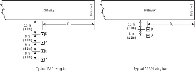
INSTALLATION TOLERANCES | |
a)Where a PAPI or APAPI is installed on a runway not equipped with an ILS or MLS, the distance D1 should be calculated to ensure that the lowest height at which a pilot will see a correct approach path indication (Figure M-5, angle B for a PAPI and angle A for an APAPI) provides the wheel clearance over the threshold specified in Table M-1 for the most demanding amongst aeroplanes regularly using the runway. b)Where a PAPI or APAPI is installed on a runway equipped with an ILS and/or MLS, the distance D1 should be calculated to provide the optimum compatibility between the visual and non-visual aids for the range of eye-to-antenna heights of the aeroplanes regularly using the runway. The distance should be equal to that between the threshold and the effective origin of the ILS glide path or MLS minimum glide path, as appropriate, plus a correction factor for the variation of eye-to-antenna heights of the aeroplanes concerned. The correction factor is obtained by multiplying the average eye-to-antenna height of those aeroplanes by the cotangent of the approach angle. However, the distance should be such that in no case will the wheel clearance over the threshold be lower than that specified in column (3) of Table M-1. Note: See CS ADR-DSN.L.540 for specifications on aiming point marking. Further guidance on the harmonisation of PAPI, ILS and/or MLS signals is contained in ICAO Doc 9157, Aerodrome Design Manual, Part 4, Visual Aids. | c)If a wheel clearance, greater than that specified in a) above is required for specific aircraft, this can be achieved by increasing D1. d)Distance D1 should be adjusted to compensate for differences in elevation between the lens centres of the light units and the threshold. e)To ensure that units are mounted as low as possible and to allow for any transverse slope, small height adjustments of up to 5 cm between units are acceptable. A lateral gradient not greater than 1.25 per cent can be accepted provided it is uniformly applied across the units. f)A spacing of 6 m (±1 m) between PAPI units should be used on code numbers 1 and 2. In such an event, the inner PAPI unit should be located not less than 10 m (±1 m) from the runway edge. Note: Reducing the spacing between light units results in a reduction in usable range of the system. g)The lateral spacing between APAPI units may be increased to 9 m (±1 m) if greater range is required or later conversion to a full PAPI is anticipated. In the latter case, the inner APAPI unit should be located 15 m (±1 m) from the runway edge. |
Figure M-4. Siting of PAPI and APAPI
[Issue: ADR-DSN/3]
[Issue: ADR-DSN/4]
GM1 ADR-DSN.M.645 Precision approach path indicator and Abbreviated precision approach path indicator (PAPI and APAPI)
ED Decision 2016/027/R
intentionally left blank
[Issue: ADR-DSN/3]
CS ADR-DSN.M.650 Approach slope and elevation setting of light units for PAPI and APAPI
ED Decision 2022/006/R
(a)Approach slope:
(1)The approach slope as defined in Figure M-5, should be so designed to be appropriate for use by the aeroplanes in the approach.
(2)When the runway is equipped with an ILS and/or MLS, the siting and the angle of elevation of the light units should be such that the visual approach slope conforms as closely as possible with the glide path of the ILS and/or the minimum glide path of the MLS, as appropriate.
(b)Elevation setting of light units
(1)The angle of elevation settings of the light units in a PAPI wing bar should be such that, during an approach, the pilot of an aeroplane observing a signal of one white and three reds should clear all objects in the approach area by a safe margin (see Table M-1).
(2)The angle of elevation settings of the light units in an APAPI wing bar should be such that, during an approach, the pilot of an aeroplane observing the lowest on-slope signal, i.e. one white and one red, should clear all objects in the approach area by a safe margin (see Table M-1).
(3)The azimuth spread of the light beam should be suitably restricted where an object located outside the obstacle protection surface of the PAPI or APAPI system but within the lateral limits of its light beam, is found to extend above the plane of the obstacle protection surface and a safety assessment indicates that the object could adversely affect the safety of operations. The extent of the restriction should be such that the object remains outside the confines of the light beam.
(4)Where wing bars are installed on each side of the runway to provide roll guidance, corresponding units should be set at the same angle so that the signals of each wing bar change symmetrically at the same time.
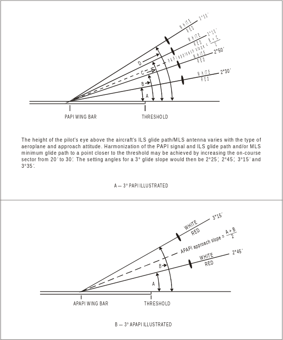
Figure M-5. Light beams and angle of elevation setting of PAPI and APAPI
Eye-to-wheel height of aeroplane in the approach configurationa | Desired wheel clearance (metres)b, c | Minimum wheel clearance (metres)d |
(1) | (2) | (3) |
up to but not including 3 m | 6 | 3e |
3 m up to but not including 5 m | 9 | 4 |
5 m up to but not including 8 m | 9 | 5 |
8 m up to but not including 14 m | 9 | 6 |
a.In selecting the eye-to-wheel height group, only aeroplanes meant to use the system on a regular basis should be considered. The most demanding amongst such aeroplanes should determine the b.Where practicable, the desired wheel clearances shown in column (2) should be provided. c.The wheel clearances in column (2) should be reduced to no less than those in column (3) where a safety assessment indicates that such reduced wheel clearances are acceptable. d.When a reduced wheel clearance is provided at a displaced threshold, it should be ensured that the corresponding desired wheel clearance specified in column (2) should be available when an aeroplane at the top end of the eye-to-wheel height group chosen overflies the extremity of the runway. e.This wheel clearance should be reduced to 1.5 m on runways used mainly by light-weight non-turbo-jet aeroplanes. | ||
Table M-1. Wheel clearance over threshold for PAPI and APAPI
[Issue: ADR-DSN/3]
[Issue: ADR-DSN/6]
GM1 ADR-DSN.M.650 Approach slope and elevation setting of light units for PAPI and APAPI
ED Decision 2016/027/R
intentionally left blank
[Issue: ADR-DSN/3]