
Filters
CS ADR-DSN.E.355 Strength of aprons
ED Decision 2014/013/R
Each part of an apron should be capable of withstanding the traffic of the aircraft it is intended to serve, due consideration being given to the fact that some portions of the apron should be subjected to a higher density of traffic and, as a result of slow moving or stationary aircraft, to higher stresses than a runway.
GM1 ADR-DSN.E.355 Strength of aprons
ED Decision 2022/006/R
(a)Apron pavement protection against fuel: On aircraft stands, pavement surface in bituminous concrete and joints between concrete slabs should be protected from fuel effects.
(b)Fuel on bituminous concrete provokes a disintegration of the concrete which becomes a kind of dark powder. On aircraft stands, it is not rare to have fuel on the pavement surface, due to leakage from aircraft or refuelling devices or due to a wrong move during refuelling. Therefore, if the aircraft stand pavement is in bituminous concrete, a specific protection is considered. Such protection is:
(1)a surface protection consisting in an overlay with a material inert against fuel; or
(2)a product incorporated in the mass of the bituminous concrete during its fabrication, protecting aggregates and binder.
(c)The first solution has the disadvantages to be fragile against stamping effects due to aircraft at the stand but is very useful for existing pavement protection.
(d)Taking into account the stamping due to aircraft at stands and the weakness of bituminous concrete against fuel, the aircraft stand pavements are often in cement concrete, which offers a much better resistance to stamping and to fuel. Nevertheless, joints between cement concrete slabs could be also damaged by fuel. According to the location of such joints regarding aircraft location and refuelling devices location, it is preferable to manufacture such joints in a material resistant to the fuel.
(e)The method for reporting the bearing strength of the pavement is available in Part-ADR.OPS of Regulation (EU) No 139/2014.
(f)Additional information on the bearing strength, the design and evaluation of pavements is given in ICAO Doc 9157, Aerodrome Design Manual, Part 3, Pavements.
[Issue: ADR-DSN/6]
CS ADR-DSN.E.360 Slopes on aprons
ED Decision 2016/027/R
(a)Slopes on an apron, including those on an aircraft stand taxilane, should be sufficient to prevent accumulation of water on the surface of the apron but should be kept to the minimum required to facilitate effective drainage.
(b)On an aircraft stand the maximum slope should not exceed 1 % in any direction.
[Issue: ADR-DSN/3]
GM1 ADR-DSN.E.360 Slopes on aprons
ED Decision 2022/006/R
(a)The design of slopes should direct spilled fuel away from building and apron service areas. Where such slopes are unavoidable, special measures should be taken to reduce the fire hazard resulting from fuel spillage.
(b)Slopes on apron have the same purpose as other pavement slopes, meaning to prevent the accumulation of water (or possible fluid contaminant) on the surface and to facilitate rapid drainage of surface water (or possible fluid contaminant). Nevertheless, the design of the apron, especially for the parts containing aircraft stands, should specifically take into account the impact of the slopes on the aircraft during its braking at the stand and during its start for departure (with push-back or with its own engines). The aims are, on the one hand, to avoid that an aircraft passes its stop point and goes on the apron service road or to the closest building and on the other hand, to save fuel and optimise the manoeuvrability of the aircraft or of the push-back device.
(c)Where the slope limitation of 1 % on the stands cannot be achieved, the slope should be kept as shallow as possible and should be such that the operation of the aircraft and vehicles is not compromised.
[Issue: ADR-DSN/3]
[Issue: ADR-DSN/6]
CS ADR-DSN.E.365 Clearance distances on aircraft stands
ED Decision 2016/027/R
(a)The safety objective of clearance distances on aircraft stands is to provide safe separation between an aircraft using the stand and any adjacent building, aircraft on another stand and other objects.
(b)An aircraft stand should provide the following minimum clearances between an aircraft entering or exiting the stand and any adjacent building, aircraft on another stand and other objects:
Code Letter | Clearance |
A | 3 m |
B | 3 m |
C | 4.5 m |
D | 7.5 m |
E | 7.5 m |
F | 7.5 m |
(c)The minimum clearance distance for code letters D, E and F can be reduced:
(1)for height limited objects,
(2)if the stand is restricted for aircraft with specific characteristics,
(3)in the following locations (for aircraft using a taxi-in, push-back procedure only):
(i)between the terminal (including passenger loading bridges) and the nose of an aircraft; and
(ii)over a portion of the stand provided with azimuth guidance by a visual docking guidance system.
[Issue: ADR-DSN/3]
GM1 ADR-DSN.E.365 Clearance distances on aircraft stands
ED Decision 2017/021/R
(a)Reduced separation at the gate is possible where azimuth guidance by a visual docking guidance system is provided, in combination with additional mitigation measures, such as:
(1)good condition of marking and signage;
(2)maintenance of visual docking systems.
(b)On aircraft stands, where reduced clearance distances are applied:
(1)Guidance by a visual docking guidance system should be provided.
(2)All objects for which reduced clearances apply should be properly marked or lighted (see Chapter Q Visual Aids for Denoting Obstacles).
(3)Aircraft stands where reduced clearance distances apply should be identified and the information published in the AIP.
(4)For code letters D, E or F, an aircraft stand equipped with a visual docking guidance system the minimum clearance of 4.5 metres may be applied between an aircraft entering or exiting the stand and any adjacent building, aircraft on another stand or other objects.
(5)For code letter C an aircraft stand equipped with a visual docking guidance system the minimum clearance of 3 metres may be applied between an aircraft entering or exiting the stand and any adjacent building, aircraft on another stand or other objects if a safety assessment indicates that such reduction would not affect the safety of operations of aircraft.
(c)Any aircraft passing behind an aircraft parked on an aircraft stand should keep the required clearance distances defined in Table D-1.
[Issue: ADR-DSN/3]
[Issue: ADR-DSN/4]
CHAPTER F — ISOLATED AIRCRAFT PARKING POSITION
CS ADR-DSN.F.370 Isolated aircraft parking position
ED Decision 2014/013/R
(a)The safety objective of the isolated aircraft parking position is to provide safe separation between aircraft that need isolation and other aerodrome activities.
(b)General
An isolated aircraft parking position should be designated by the aerodrome operator for parking of aircraft that needs isolation from normal aerodrome activities.
(c)Location
The isolated aircraft parking position should be located at the maximum distance practicable and in any case never less than 100 m from other parking positions, buildings, or public areas, etc.
GM1 ADR-DSN.F.370 Isolated aircraft parking position
ED Decision 2014/013/R
Care should be taken to ensure that the position is not located over underground utilities, such as gas and aviation fuel and, to the extent feasible, electrical or communication cables. The aerodrome control tower should be advised of an area or areas suitable for the parking of an aircraft.
CHAPTER G — DE-ICING/ANTI-ICING FACILITIES
CS ADR-DSN.G.375 General
ED Decision 2014/013/R
Aeroplane de-icing/anti-icing facilities should be provided at an aerodrome where icing conditions are expected to occur.
GM1 ADR-DSN.G.375 General
ED Decision 2014/013/R
Combinations of ice, snow and/or standing water may, especially when rain, rain and snow, or snow is falling, produce substances with specific gravities in excess of 0.8. These substances, due to their high water/ice content, should have a transparent rather than a cloudy appearance and, at the higher specific gravities, should be readily distinguishable from slush.
CS ADR-DSN.G.380 Location
ED Decision 2022/006/R
(a)De-icing/anti-icing facilities should be provided either at aircraft stands or at specified remote areas.
(b)The remote de-icing/anti-icing facilities should be located to be clear of the obstacle limitation surfaces, not cause interference to the radio navigation aids and be clearly visible from the air traffic control tower for clearing the treated aeroplane.
[Issue: ADR-DSN/6]
GM1 ADR-DSN.G.380 Location
ED Decision 2022/006/R
(a)The de-icing/anti-icing facilities should be so located as to ensure that the holdover time of the anti-icing treatment is still in effect at the end of taxiing, and when take-off clearance of the treated aeroplane is given.
(b)To further maximise departure flow rates for all aeroplanes, the location and size of de-icing/anti-icing facilities should be such that they allow for bypass taxiing during de-icing/anti-icing operations. Additional guidance is given in ICAO Doc 9640, Manual of aircraft ground de-icing/anti-icing operations, paragraph 8.5(e).
(c)Remote de-icing/anti-icing facilities located near departure runway ends or along taxiways are recommended when taxi times from terminals or off-terminal de-icing/anti-icing locations frequently exceed holdover times.
(d)Remote facilities compensate for changing weather conditions when icing conditions or blowing snow are expected to occur along the taxi-route taken by the aeroplane to the runway meant for take-off.
(e)The remote de-icing/anti-icing facilities should be so located as to provide for an expeditious traffic flow, perhaps with a bypass configuration, and not require unusual taxiing manoeuvre into and out of the pads.
(f)The jet blast effects caused by a moving aeroplane on other aeroplanes receiving the anti-icing treatment or taxiing behind should have to be taken into account to prevent degradation of the treatment.
[Issue: ADR-DSN/3]
[Issue: ADR-DSN/6]
CS ADR-DSN.G.385 Size of de-icing/anti-icing pads
ED Decision 2014/013/R
(a)The safety objective of the de-icing/anti-icing pad dimensions is to allow safe positioning of aircraft for de-icing/anti-icing, including sufficient room for the safe movement of de-icing vehicles around the aircraft.
(b)The size of a de-icing/anti-icing pad should be equal to the parking area required by the most demanding aircraft in a given category with at least 3.8 m clear paved area all around the aeroplane for the movement of the de-icing/anti-icing vehicles.
GM1 ADR-DSN.G.385 Size of de-icing/anti-icing pads
ED Decision 2016/027/R
(a)It is recommended that the aerodrome have facilities with a de-icing/anti-icing capability equivalent to the maximum peak hour departure rate that can be managed by the ATC units during de-icing/anti-icing operations. Additional guidance is given in ICAO Doc 9640, Manual of aircraft ground de-icing/anti-icing operations, paragraph 8.3.
(b)The number of de-icing/anti-icing pads required should be determined based on the meteorological conditions, the type of aeroplanes to be treated, the method of application of de-icing/anti-icing fluid, the type and capacity of the dispensing equipment used, and the volume of traffic and departure flow rates.
(c)An aeroplane de-icing/anti-icing pad consists of:
(1)an inner area for parking of an aeroplane to be treated; and
(2)an outer area for movement of two or more mobile de-icing/anti-icing equipment.
(d)Where more than one de-icing/anti-icing pad is provided, consideration should be given to providing de-icing/anti-icing vehicle movement areas of adjacent pads that do not overlap but are exclusive for each pad. Consideration should also be given to bypassing of the area by other aeroplanes with the clearances specified in CS ADR-DSN.G.400.
[Issue: ADR-DSN/3]
CS ADR-DSN.G.390 Slopes on de-icing/anti-icing pads
ED Decision 2014/013/R
The de-icing/anti-icing pads should be provided with suitable slopes:
(a)to ensure satisfactory drainage of the area;
(b)to permit collection of all excess de-icing/anti-icing fluid running off an aeroplane; and
(c)not to hinder the movement of aircraft on or off the pad.
GM1 -ADR-DSN.G.390 Slopes on de-icing/anti-icing pads
ED Decision 2014/013/R
It is recommended that the drainage arrangements for the collection and safe disposal of excess de-icing/anti-icing fluids prevent ground water contamination.
CS ADR-DSN.G.395 Strength of de-icing/anti-icing pads
ED Decision 2014/013/R
The de-icing/anti-icing pad should be capable of withstanding the traffic of the aircraft it is intended to serve.
GM1 ADR-DSN.G.395 Strength of de-icing/anti-icing pads
ED Decision 2014/013/R
Consideration should be given to the fact that the de-icing/anti-icing pad (in common with an apron) should be subjected to a higher density of traffic and, as a result of slow-moving or stationary aircraft, to higher stresses than a runway.
CS ADR-DSN.G.400 Clearance distances on a de-icing/anti-icing pad
ED Decision 2016/027/R
(a)The safety objective of the clearance distances on a de-icing/anti-icing pad is to provide safe separation between an aircraft using the stand and any adjacent building, aircraft on another stand and other objects.
(b)A de-icing/anti-icing pad should provide the following minimum clearances between an aircraft using the stand and any adjacent building, aircraft on another stand and other objects:
Code Letter | Clearance |
A | 3.8 m |
B | 3.8 m |
C | 4.5 m |
D | 7.5 m |
E | 7.5 m |
F | 7.5 m |
(c)If the pad layout is such as to include bypass configuration, the minimum separation distances specified in Table D-1, column (13) should be provided.
(d)Where the de-icing/anti-icing facility is located adjoining a regular taxiway, the taxiway minimum separation distance specified in Table D-1, column (11) should be provided (see Figure G-1).
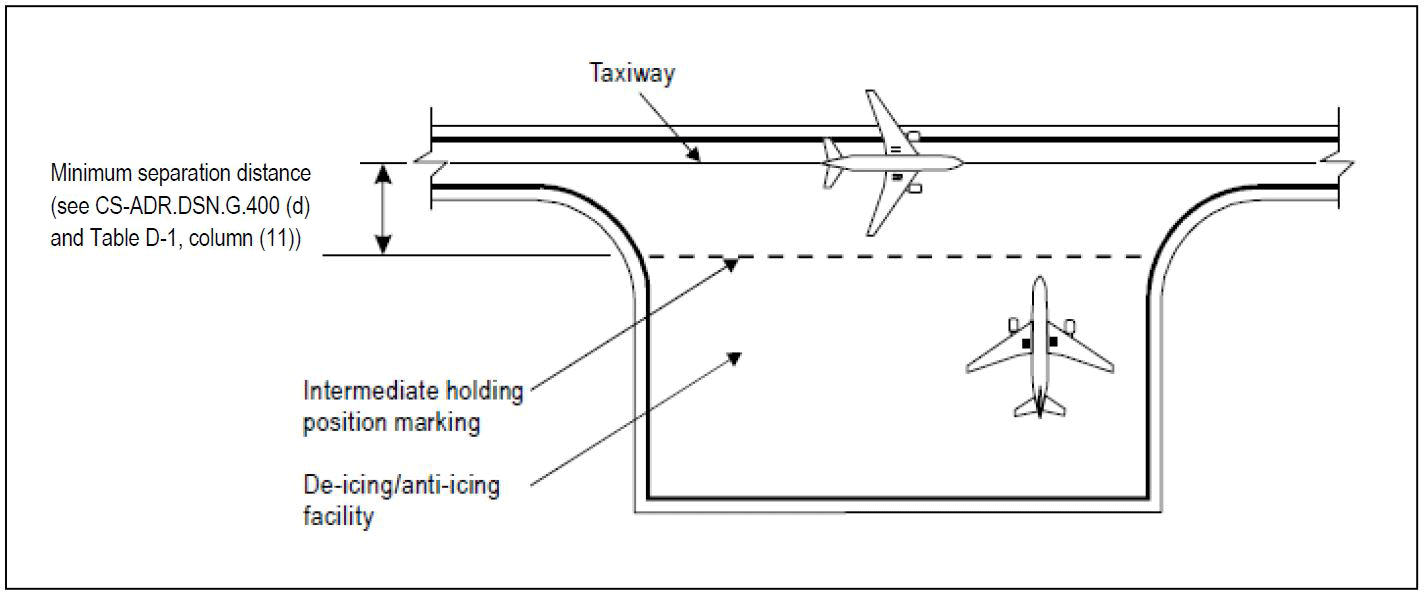
Figure G-1. Minimum separation distance on a de-icing/anti-icing facility
[Issue: ADR-DSN/2]
[Issue: ADR-DSN/3]
GM1 ADR-DSN.G.400 Clearance distances on a de-icing/anti-icing pad
ED Decision 2022/006/R
(a)The separation criteria should take into account the need for individual de-icing/anti-icing pads to provide sufficient manoeuvring area around the aircraft to allow simultaneous treatment by two or more mobile de-icing/anti-icing vehicles and sufficient non-overlapping space for a vehicle safety zone between adjacent de-icing pads and for other de-icing/anti-icing pads.
(b)The minimum clearance distance of 3.8 m is necessary for the movement of de-icing/anti-icing vehicles round the aircraft.
(c)Where the de-icing/anti-icing facility is located in a non-movement area, the minimum clearance distance can be reduced.
[Issue: ADR-DSN/6]
CHAPTER H — OBSTACLE LIMITATION SURFACES
CS ADR-DSN.H.405 Applicability
ED Decision 2014/013/R
Applicability: The purpose of the obstacle limitation surfaces is to define the airspace around aerodromes to be maintained free from obstacles so as to permit the intended aeroplane operations at the aerodromes to be conducted safely.
GM1 ADR-DSN.H.405 Applicability
ED Decision 2021/004/R
(a)The obstacle limitation surfaces define the limits to which objects may project into the airspace. Each surface is related to one or more phases of a flight, and provides protection to aircraft during that phase.
(b)The OLS also help to prevent the aerodromes from becoming unusable by the growth of obstacles around the aerodromes.
(c)The effective utilisation of an aerodrome may be considerably influenced by natural features and man-made constructions outside its boundary. These may result in limitations on the distance available for take-off and landing and on the range of meteorological conditions in which take-off and landing can be undertaken. For these reasons, certain areas of the local airspace should be regarded as integral parts of the aerodrome environment.
(d)Objects which penetrate the obstacle limitation surfaces may in certain circumstances cause an increase in the obstacle clearance altitude/height for an instrument approach procedure or any associated visual circling procedure or have other operational impact on flight procedure design. Criteria for flight procedure design are contained in the Procedures for Air Navigation Services — Aircraft Operations (ICAO, PANS-OPS, Doc 8168).
(e)In ideal circumstances all the surfaces should be free from obstacles but when a surface is infringed, any safety measures required should have regard to:
(1)the nature of the obstacle and its location relative to the surface origin, to the extended centre line of the runway or normal approach and departure paths, and to existing obstructions;
(2)the amount by which the surface is infringed;
(3)the gradient presented by the obstacle to the surface origin;
(4)the type of air traffic at the aerodrome; and
(5)the instrument approach procedures published for the aerodrome.
(f)Safety measures could be as follows:
(1)promulgation in the AIP of appropriate information;
(2)marking and/or lighting of the obstacle;
(3)variation of the runway distances declared as available;
(4)limitation of the use of the runway to visual approaches only;
(5)restrictions on the type of traffic.
(g)In addition to the requirements described in the certification specifications of Chapter H, it may be necessary to call for other restrictions to development and construction on and in the vicinity of the aerodrome in order to protect the performance of visual and electronic aids to navigation and to ensure that such development does not adversely affect instrument approach procedures and the associated obstacle clearance limits.
[Issue: ADR-DSN/5]
CS ADR-DSN.H.410 Outer horizontal surface
ED Decision 2014/013/R
intentionally left blank
GM1 ADR-DSN.H.410 Outer horizontal surface
ED Decision 2016/027/R
(a)The outer horizontal surface should extend from the periphery of the conical surface as shown in Figure GM-H-1. An outer horizontal surface is a specified portion of a horizontal plane around an aerodrome beyond the limits of the conical surface. It represents the level above which consideration needs to be given to the control of new obstacles in order to facilitate practicable and efficient instrument approach procedures, and together with the conical and inner horizontal surfaces to ensure safe visual manoeuvring in the vicinity of an aerodrome.
(b)The outer horizontal surface is of particular importance for safe operations in areas of high ground or where there are concentrations of obstacles.
(c)In the experience of some States, operational problems can arise from the erection of tall structures in the vicinity of aerodromes beyond the areas currently recognised in these aerodrome regulations and ICAO Annex 14 as areas in which restriction of new construction may be necessary. Such problems may be addressed through the provision of an outer horizontal surface, which is a specified portion of a horizontal plane around an aerodrome beyond the limits of the conical surface. It represents the level above which consideration needs to be given to the control of new obstacles in order to facilitate practicable and efficient instrument approach procedures, and together with the conical and inner horizontal surfaces to ensure safe visual manoeuvring in the vicinity of an aerodrome.
(d)As a broad specification for the outer horizontal surface, tall structures can be considered to be of possible significance if they are both higher than 30 m above local ground level, and higher than 150 m above aerodrome elevation within a radius of 15 000 m of the centre of the airport where the runway code number is 3 or 4. The area of concern may need to be extended to coincide with the PANS OPS obstacle areas for the individual approach procedures at the airport under consideration.
(e)Guidance on Outer Horizontal Surface is included in ICAO Doc 9137, Airport Services Manual, Part 6, Control of Obstacles.
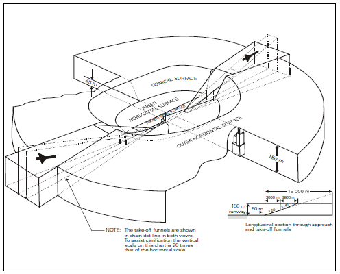
Figure GM-H-1. Disposition of Outer Horizontal Surface
[Issue: ADR-DSN/3]
CS ADR-DSN.H.415 Conical surface
ED Decision 2014/013/R
(a)Applicability: The purpose of the conical surface is to facilitate safe visual manoeuvring in the vicinity of the aerodrome.
(b)Description: A surface sloping upwards and outwards from the periphery of the inner horizontal surface.
(c)Characteristics: The limits of the conical surface should comprise:
(1)a lower edge coincident with the periphery of the inner horizontal surface; and
(2)an upper edge located at a specified height above the inner horizontal surface.
(d)The slope of the conical surface should be measured in a vertical plane perpendicular to the periphery of the inner horizontal surface.
GM1 ADR-DSN.H.415 Conical surface
ED Decision 2014/013/R
intentionally left blank
CS ADR-DSN.H.420 Inner horizontal surface
ED Decision 2016/027/R
(a)Applicability: The purpose of the inner horizontal surface is to protect airspace for visual manoeuvring prior to landing.
(b)Description: A surface located in a horizontal plane above an aerodrome and its environs.
(c)Characteristics: The outer limits of the inner horizontal surface are defined by a circle centred on the geometric centre of the runway, by a convex contour composed of circular arcs centred on the intersections of the extended RWY centre line with the end of the RWY strip, joined tangentially by straight lines parallel to the runway centre line, as shown in Figure H-1, or on other points established for such purpose.
(d)The height of the inner horizontal surface should be measured above an established elevation datum. The elevation datum used for the height of the inner horizontal surface should be:
(1)the elevation of the highest point of the lowest threshold of the related runway; or
(2)the elevation of the highest point of the highest threshold of the related runway; or
(3)the elevation of the highest point of the runway; or
(4)the aerodrome elevation.
[Issue: ADR-DSN/3]
GM1 ADR-DSN.H.420 Inner horizontal surface
ED Decision 2016/027/R
(a)The shape of the inner horizontal surface need not necessarily be circular. Guidance on determining the extent of the inner horizontal surface is contained in the ICAO Doc 9137, Airport Services Manual, Part 6, Control of Obstacles.
(b)The limits of the inner horizontal surface for longer runways (1 800 m or more in length) are defined as circles of radius 4 000 m centred on the strip ends of the runway. These circles are joined by common tangents parallel to the runway centre line to form a racetrack pattern. The boundary of this pattern is the boundary of the inner horizontal surface.
(c)For runways less than 1 800 m in length, the inner horizontal surface may be defined as a circle centred on the midpoint of the runway.
(d)To protect two or more runways, a more complex pattern could become necessary. In this situation, all the circles are joined tangentially by straight lines: illustrated at the Figure GM-H-2.
(e)For relatively level runways the selection of elevation datum location is not critical, but when the thresholds differ by more than 6 m, the elevation datum should regard to the factors as the elevation of the most frequent used altimeter setting datum points, minimum circling altitudes in use or required and the nature of operations at the aerodrome. For more complex inner horizontal surfaces, with runways on different levels, as shown in Figure GM-H-2, a common elevation is not essential, but where surfaces overlap, the lower surface should be regarded as dominant.
(f)Further guidance is given in ICAO Doc 9137, Airport Services Manual, Part 6, Control of Obstacles.
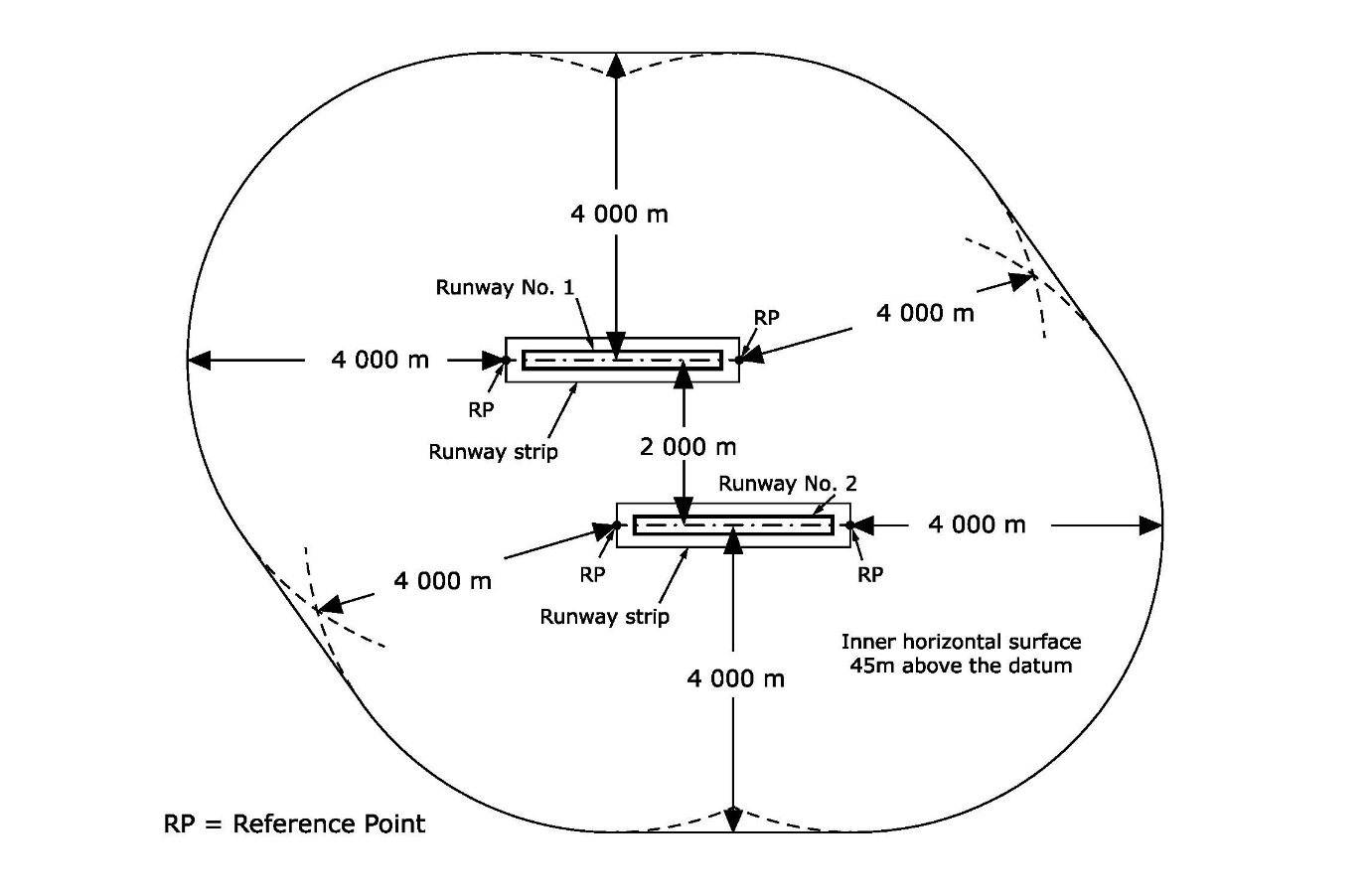
Figure GM-H-2. Composite inner horizontal surface for two parallel runways (where the runway code is 4)
[Issue: ADR-DSN/3]
CS ADR-DSN.H.425 Approach surface
ED Decision 2014/013/R
(a)Applicability: The purpose of the approach surface is to protect an aircraft during the final approach to the runway by defining the area that should be kept free from obstacles to protect an aeroplane in the final phase of the approach-to-land manoeuvre.
(b)Description: An inclined plane or combination of planes preceding the threshold.
(c)Characteristics. The limits of the approach surface should comprise:
(1)an inner edge of specified length, horizontal and perpendicular to the extended centre line of the runway, and located at a specified distance before the threshold;
(2)two sides originating at the ends of the inner edge and diverging uniformly at a specified rate from the extended centre line of the runway; and
(3)an outer edge parallel to the inner edge.
The above surfaces should be varied when lateral offset, offset or curved approaches are utilised, specifically, two sides originating at the ends of the inner edge and diverging uniformly at a specified rate from the extended centre line of the lateral offset, offset or curved ground track.
(d)The elevation of the inner edge should be equal to the elevation of the mid-point of the threshold.
(e)The slope(s) of the approach surface should be measured in the vertical plane containing the centre line of the runway and should continue containing the centre line of any lateral offset or curved ground track.
GM1 ADR-DSN.H.425 Approach surface
ED Decision 2014/013/R
intentionally left blank
CS ADR-DSN.H.430 Transitional surface
ED Decision 2014/013/R
(a)Applicability: The purpose of the transitional surface is to define the limit of the area available for buildings, other structures or natural obstructions, such as trees.
(b)Description: A complex surface along the side of the strip and part of the side of the approach surface that slopes upwards and outwards to the inner horizontal surface.
(c)Characteristics: The limits of a transitional surface should comprise:
(1)a lower edge beginning at the intersection of the side of the approach surface with the inner horizontal surface and extending down the side of the approach surface to the inner edge of the approach surface and from there along the length of the strip parallel to the runway centre line; and
(2)an upper edge located in the plane of the inner horizontal surface.
(d)The elevation of a point on the lower edge should be:
(1)along the side of the approach surface — equal to the elevation of the approach surface at that point; and
(2)along the strip — equal to the elevation of the nearest point on the centre line of the runway or its extension.
(e)The slope of the transitional surface should be measured in a vertical plane at right angles to the centre line of the runway.
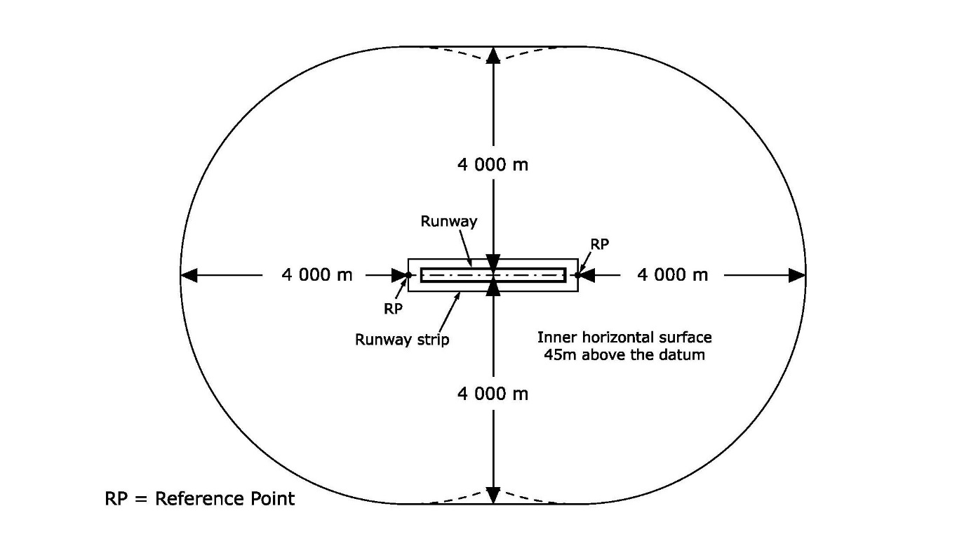
Figure H-1. Inner horizontal surface where the runway is code 4
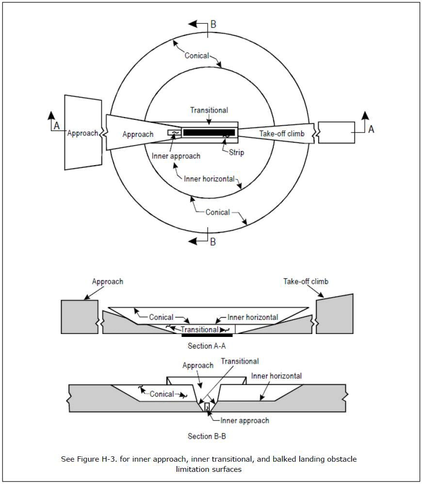
Figure H-2. Obstacle limitation surfaces
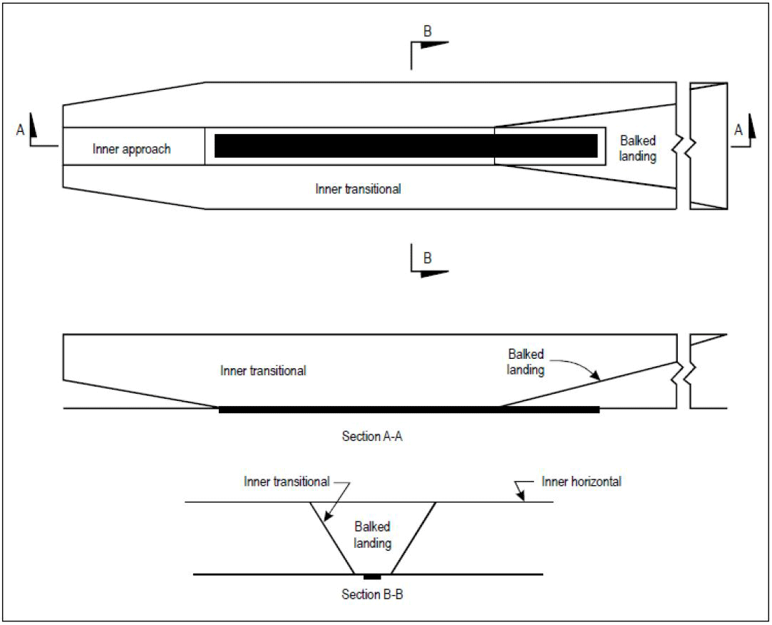
Figure H-3. Inner approach, inner transitional, and balked landing obstacle limitation surfaces
GM1 ADR-DSN.H.430 Transitional surface
ED Decision 2014/013/R
When the elevation of a point on the lower edge is along the strip and equal to the elevation of the nearest point on the centre line of the runway or its extension as a result the transitional surface along the strip should be curved if the runway profile is curved, or a plane if the runway profile is a straight line. The intersection of the transitional surface with the inner horizontal surface should also be a curved or a straight line depending on the runway profile.
CS ADR-DSN.H.435 Take-off climb surface
ED Decision 2014/013/R
(a)Applicability: The purpose of the take-off climb surface is to protect an aircraft on take-off and during climb-out.
(b)Description: An inclined plane or other specified surface beyond the end of a runway or clearway.
(c)Characteristics: The limits of the take-off climb surface should comprise:
(1)an inner edge horizontal and perpendicular to the centre line of the runway, and located either at a specified distance beyond the end of the runway, or at the end of the clearway when such is provided, and its length exceeds the specified distance;
(2)two sides originating at the ends of the inner edge, diverging uniformly at a specified rate from the take-off track to a specified final width and continuing thereafter at that width for the remainder of the length of the take-off climb surface; and
(3)an outer edge horizontal and perpendicular to the specified take-off track.
(d)The elevation of the inner edge should be equal to the highest point on the extended runway centre line between the end of the runway and the inner edge, except that when a clearway is provided, the elevation should be equal to the highest point on the ground on the centre line of the clearway.
(e)In the case of a straight take-off flight path, the slope of the take-off climb surface should be measured in the vertical plane containing the centre line of the runway.
(f)In the case of a take-off flight path involving a turn, the take-off climb surface should be a complex surface containing the horizontal normals to its centre line, and the slope of the centre line should be the same as that for a straight take-off flight path.
GM1 ADR-DSN.H.435 Take-off climb surface
ED Decision 2014/013/R
intentionally left blank
CS ADR-DSN.H.440 Slewed take-off climb surface
ED Decision 2014/013/R
intentionally left blank
GM1 ADR-DSN.H.440 Slewed take-off climb surface
ED Decision 2016/027/R
The edge of a Take-off climb surface may be slewed in the direction of a turn away from the extended runway centre line up to a maximum of 15° splay. The portion of take-off climb surface encompassing the new departure track should be the same shape and dimensions as the original take-off climb surface measured relative to the new departure track. The opposite edge of the take-off climb surface should remain unchanged unless there is another turning departure towards that side as well, in which case, the edge may be slewed in that direction too.
[Issue: ADR-DSN/3]
CS ADR-DSN.H.445 Obstacle-free zone (OFZ)
ED Decision 2016/027/R
(a)An OFZ is intended to protect aeroplanes from fixed and mobile obstacles during Category II and III operations when approaches are continued below decision height, and during any subsequent missed approach or balked landing with all engines operating normally. It is not intended to supplant the requirement of other surfaces or areas where these are more demanding.
(b)The OFZ is made up of the following obstacle limitation surfaces:
(1)inner approach surface;
(2)inner transitional surfaces; and
(3)balked landing surface.
[Issue: ADR-DSN/3]
GM1 ADR-DSN.H.445 Obstacle-free zone (OFZ)
ED Decision 2016/027/R
intentionally left blank
[Issue: ADR-DSN/3]
CS ADR-DSN.H.450 Inner approach surface
ED Decision 2014/013/R
(a)Applicability: The purpose of the inner approach surface is to protect final precision approaches.
(b)Description: A rectangular portion of the approach surface immediately preceding the threshold.
(c)Characteristics: The limits of the inner approach surface should comprise:
(1)an inner edge coincident with the location of the inner edge of the approach surface but of its own specified length;
(2)two sides originating at the ends of the inner edge and extending parallel to the vertical plane containing the centre line of the runway; and
(3)an outer edge parallel to the inner edge.
GM1 ADR-DSN.H.450 Inner approach surface
ED Decision 2014/013/R
intentionally left blank
CS ADR-DSN.H.455 Inner transitional surface
ED Decision 2014/013/R
(a)Applicability: The purpose of the inner transitional surface is to protect aeroplanes during precision approaches and balked landing.
(b)Description: A surface similar to the transitional surface but closer to the runway.
(c)Characteristics: The limits of an inner transitional surface should comprise:
(1)a lower edge beginning at the end of the inner approach surface and extending down the side of the inner approach surface to the inner edge of that surface, from there along the strip parallel to the runway centre line to the inner edge of the balked landing surface, and from there up the side of the balked landing surface to the point where the side intersects the inner horizontal surface; and
(2)an upper edge located in the plane of the inner horizontal surface.
(d)The elevation of a point on the lower edge should be:
(1)along the side of the inner approach surface and balked landing surface — equal to the elevation of the particular surface at that point; and
(2)along the strip — equal to the elevation of the nearest point on the centre line of the runway or its extension.
(e)The slope of the inner transitional surface should be measured in a vertical plane at right angles to the centre line of the runway.
GM1 ADR-DSN.H.455 Inner transitional surface
ED Decision 2014/013/R
(a)It is intended that the inner transitional surface be the controlling obstacle limitation surface for navigation aids, aircraft, and other vehicles that should be near the runway, and which is not to be penetrated except for frangible objects. The transitional surface is intended to remain as the controlling obstacle limitation surface for buildings, etc.
(b)The inner transitional surface along the strip should be curved if the runway profile is curved or a plane if the runway profile is a straight line. The intersection of the inner transitional surface with the inner horizontal surface should also be a curved or straight line depending on the runway profile.
CS ADR-DSN.H.460 Balked landing surface
ED Decision 2014/013/R
(a)Applicability: The purpose of the balked landing surface is to protect balked landing.
(b)Description: An inclined plane located at a specified distance after the threshold, extending between the inner transitional surfaces.
(c)Characteristics: The limits of the balked landing surface should comprise:
(1)an inner edge horizontal and perpendicular to the centre line of the runway and located at a specified distance after the threshold;
(2)two sides originating at the ends of the inner edge and diverging uniformly at a specified rate from the vertical plane containing the centre line of the runway; and
(3)an outer edge parallel to the inner edge and located in the plane of the inner horizontal surface.
(d)The elevation of the inner edge should be equal to the elevation of the runway centre line at the location of the inner edge.
(e)The slope of the balked landing surface should be measured in the vertical plane containing the centre line of the runway.
GM1 ADR-DSN.H.460 Balked landing surface
ED Decision 2014/013/R
intentionally left blank
CHAPTER J — OBSTACLE LIMITATION REQUIREMENTS
CS ADR-DSN.J.465 General
ED Decision 2014/013/R
Obstacle limitation requirements should be distinguished between:
(a)non-instrument runways;
(b)non-precision approach runways;
(c)precision approach runways; and
(d)runways meant for take-off.
GM1 ADR-DSN.J.465 General
ED Decision 2014/013/R
The requirements for obstacle limitation surfaces are specified on the basis of the intended use of a runway, i.e. take-off or landing, and type of approach, and are intended to be applied when such use of the runway is made. In cases where operations are conducted to or from both directions of a runway, the function of certain surfaces may be nullified because of more stringent requirements of another lower surface.
CS ADR-DSN.J.470 Non-instrument runways
ED Decision 2016/027/R
(a)The following obstacle limitation surfaces should be established for a non-instrument runway:
(1)conical surface;
(2)inner horizontal surface;
(3)approach surface; and
(4)transitional surfaces.
(b)The heights and slopes of the surfaces should not be greater than, and their other dimensions not less than, those specified in Table J-1.
(c)New objects or extensions of existing objects should not be permitted above an approach or transitional surface except when the new object or extension would be shielded by an existing immovable object.
(d)New objects or extensions of existing objects should not be permitted above the conical surface or inner horizontal surface except when the object would be shielded by an existing immovable object, or if after a safety assessment, it is determined that the object would not adversely affect the safety or significantly affect the regularity of operations of aeroplanes.
(e)Existing objects above any of the conical surface, inner horizontal surface, approach surface and transitional surfaces should, as far as practicable, be removed except when the object is shielded by an existing immovable object, or if after a safety assessment, it is determined that the object would not adversely affect the safety or significantly affect the regularity of operations of aeroplanes.
(f)In considering proposed construction, account should be taken of the possible future development of an instrument runway and consequent requirement for more stringent obstacle limitation surfaces.
[Issue: ADR-DSN/3]
GM1 ADR-DSN.J.470 Non-instrument runways
ED Decision 2016/027/R
(a)Circumstances in which the shielding principle may reasonably be applied are described in the ICAO Doc 9137, Airport Services Manual, Part 6, Control of Obstacles.
(b)Because of transverse or longitudinal slopes on a strip, in certain cases the inner edge or portions of the inner edge of the approach surface may be below the corresponding elevation of the strip. It is not intended that the strip be graded to conform with the inner edge of the approach surface, nor is it intended that terrain or objects which are above the approach surface beyond the end of the strip, but below the level of the strip, be removed unless it is considered that they may endanger aeroplanes.
[Issue: ADR-DSN/3]
CS ADR-DSN.J.475 Non-precision approach runways
ED Decision 2016/027/R
(a)The following obstacle limitation surfaces should be established for a non-precision approach runway:
(1)conical surface;
(2)inner horizontal surface;
(3)approach surface; and
(4)transitional surfaces.
(b)The heights and slopes of the surfaces should not be greater than, and their other dimensions not less than, those specified in Table J-1, except in the case of the horizontal section of the approach surface (see paragraph (c) below).
(c)The approach surface should be horizontal beyond the point at which the 2.5 % slope intersects:
(1)a horizontal plane 150 m above the threshold elevation; or
(2)the horizontal plane passing through the top of any object that governs the obstacle clearance altitude/height (OCA/H);
whichever is the higher.
(d)New objects or extensions of existing objects should not be permitted above an approach surface within 3 000 m of the inner edge or above a transitional surface except when the new object or extension would be shielded by an existing immovable object.
(e)New objects or extensions of existing objects should not be permitted above the approach surface beyond 3 000 m from the inner edge, the conical surface or inner horizontal surface except when the object would be shielded by an existing immovable object, or after an safety assessment, it is determined that the object would not adversely affect the safety or significantly affect the regularity of operations of aeroplanes.
(f)Existing objects above any of the surfaces required by paragraph (a) should as far as practicable be removed except when the object would be shielded by an existing immovable object, or if after a safety assessment, it is determined that the object would not adversely affect the safety or significantly affect the regularity of operations of aeroplanes.
[Issue: ADR-DSN/3]
GM1 ADR-DSN.J.475 Non-precision approach runways
ED Decision 2016/027/R
(a)If it is of particular importance for safe operation on circuits, arrival routes towards the aerodrome or on departure or missed approach climb-paths, an outer horizontal surface for non-precision approach runways should be established.
(b)Circumstances in which the shielding principle may reasonably be applied are described in ICAO Doc 9137, Airport Services Manual, Part 6, Control of Obstacles.
(c)Because of transverse or longitudinal slopes on a strip, in certain cases the inner edge or portions of the inner edge of the approach surface may be below the corresponding elevation of the strip. It is not intended that the strip be graded to conform with the inner edge of the approach surface, nor is it intended that terrain or objects which are above the approach surface beyond the end of the strip, but below the level of the strip, be removed unless it is considered they may endanger aeroplanes.
[Issue: ADR-DSN/3]