
Filters
List of abbreviations
ED Decision 2022/006/R
List of abbreviations
(used in CS-ADR-DSN)
AGL | Above ground level |
AGL | Aeronautical ground light |
AIP | Aeronautical information publication |
AIS | Aeronautical information services |
APAPI | Abbreviated precision approach path indicator |
ARC | Aerodrome reference code |
ARIWS | Autonomous runway incursion warning systems |
ASDA | Accelerate-stop distance available |
A-SMGCS | Advanced surface movement guidance and control system |
ATC | Air traffic control |
ATIS | Automatic terminal information service |
ATM | Air traffic management |
ATS | Air traffic services |
A-VDGS | Advanced visual docking guidance system |
CBR | California bearing ratio |
CCR | Constant current regulators |
CIE | International Commission on Illumination (Commission Internationale de l’Éclairage) |
CWY | Clearway |
DH | Decision height |
DME | Distance measuring equipment |
EMAS | Engineered Materials Arresting System |
ESDU | Engineering sciences data unit |
FOD | Foreign object debris |
FOV | Field of view |
Hes | Height of equivalent elevated sign character |
Hps | Height of pavement sign character |
ICAO | International Civil Aviation Organization |
ILS | Instrument landing system |
IMC | Instrument meteorological conditions |
ISO | International Organisation for Standardisation |
LDA | Landing distance available |
LED | Light-emitting diodes |
LRST | Local runway safety team |
MLS | Microwave landing system |
MLW | Maximum landing weight |
MPD | Mean profile depth |
MTD | Mean texture depth |
MTOW | Maximum take-off weight |
NOTAM | Notice to airman |
NU | Not usable |
OCA/H | Obstacle clearance altitude/ height |
OFZ | Obstacle-free zone |
OLS | Obstacle limitation surface |
OMGWS | Outer main gear wheel span |
OPS | Obstacle protection surface |
PAPI | Precision approach path indicator |
PBN | Performance based navigation |
PSV | Polished stone values |
RELs | Runway entrance lights |
RESA | Runway end safety area |
RET | Rapid exit taxiway |
RETILs | Rapid exit taxiway indicator lights |
RFF | Rescue and firefighting |
RFFS | Rescue and firefighting services |
RP | Reference point |
RVR | Runway visual range |
RWSL | Runway status lights |
RWY | Runway |
SMGCS | Surface movement guidance and control system |
SWY | Stopway |
TDZ | Runway touchdown zone |
THLs | Take-off hold lights |
TODA | Take-off distance available |
TORA | Take-off run available |
UPS | Uninterruptible power supply |
VMC | Visual meteorological conditions |
VOR | VHF Omnidirectional radio range |
WGS-84 | World geodetic system – 1984 |
CHAPTER A — GENERAL
CS ADR-DSN.A.001 Applicability
ED Decision 2021/004/R
The certification specifications (CSs) and the related guidance material (GM) are applicable to aerodromes that fall within the scope of Regulation (EU) 2018/1139 (Basic Regulation).
[Issue: ADR-DSN/5]
GM1 ADR-DSN.A.001 Applicability
ED Decision 2021/004/R
At an aerodrome that falls within the scope of the Basic Regulation and has more than one runway, at least one runway should meet the criteria contained in Article 2 of the Basic Regulation. However, it is not compulsory for other ‘types’ of runways at an aerodrome to meet the criteria of Article 2 of the Basic Regulation. Such runways may be non-instrument runways, unpaved runways, shorter than 800 m runways, runways which are not open to public use or for commercial air transport. The certification specifications and guidance material are applicable also to those runways.
[Issue: ADR-DSN/5]
CS ADR-DSN.A.002 Definitions
ED Decision 2022/006/R
For the purposes of CS-ADR-DSN, the following definitions should apply:
‘Accuracy’ means a degree of conformance between the estimated or measured value and the true value.
‘Aerodrome’ means a defined area (including any buildings, installations and equipment) on land or water or on a fixed offshore or floating structure intended to be used either wholly or in part for the arrival, departure and surface movement of aircraft.
‘Aerodrome beacon’ means an aeronautical beacon used to indicate the location of an aerodrome from the air.
‘Aerodrome elevation’ means the elevation of the highest point of the landing area.
‘Aerodrome equipment’ means any equipment, apparatus, appurtenance, software or accessory, that is used or intended to be used to contribute to the operation of aircraft at an aerodrome.
‘Aerodrome operator’ means any legal or natural person, operating or proposing to operate one or more aerodromes.
‘Aerodrome traffic density’ means the number of movements in the mean busy hour and is the arithmetic mean over the year of the number of movements in the daily busiest hour. Movement is either a take-off or a landing:
(a)— Light. Where the number of movements in the mean busy hour is not greater than 15 per runway or typically less than 20 total aerodrome movements.
(b)— Medium. Where the number of movements in the mean busy hour is of the order of 16 to 25 per runway or typically between 20 to 35 total aerodrome movements.
(c)— Heavy. Where the number of movements in the mean busy hour is of the order of 26 or more per runway or typically more than 35 total aerodrome movements.
‘Aeronautical beacon’ means an aeronautical ground light visible at all azimuths, either continuously or intermittently, to designate a particular point on the surface of the earth.
‘Aeronautical ground light’ means any light specially provided as an aid to air navigation, other than a light displayed on an aircraft.
‘Aeroplane’ means a power-driven heavier-than-air aircraft, deriving its lift in flight chiefly from aerodynamic reactions on surfaces which remain fixed under given conditions of flight;
‘Aeroplane reference field length’ means the minimum field length required for take-off at maximum certificated take-off mass, sea level, standard atmospheric conditions, still air and zero runway slope, as shown in the appropriate aeroplane flight manual prescribed by the certificating authority or equivalent data from the aeroplane manufacturer. Field length means balanced field length for aeroplanes, if applicable, or take-off distance in other cases.
‘Arresting system’ means a system designed to decelerate an aeroplane overrunning the runway.
‘Autonomous runway incursion warning system (ARIWS)’ means a system which provides autonomous detection of a potential incursion or of the occupancy of an active runway and a direct warning to a flight crew or a vehicle operator.
‘Aircraft’ means a machine that can derive support in the atmosphere from the reactions of the air other than the reactions of the air against the earth’s surface.
‘Aircraft stand’ means a designated area on an apron intended to be used for parking an aircraft.
‘Aircraft stand taxilane’ means a portion of an apron designated as a taxiway and intended to provide access to aircraft stands only.
‘Apron’ means a defined area intended to accommodate aircraft for purposes of loading or unloading passengers, mail or cargo, fuelling, parking, or maintenance.
‘Apron service road’ means a road located on or adjacent to an apron, intended for the exclusive use of vehicles.
‘Apron taxiway’ means a portion of a taxiway system located on an apron and intended to provide a through taxi-route across the apron.
‘Balked landing’ means a landing manoeuvre that is unexpectedly discontinued at any point below the obstacle clearance altitude/height (OCA/H).
‘Barrette’ means three or more aeronautical ground lights closely spaced in a transverse line so that from a distance they appear as a short bar of light.
‘Certification specifications’ mean technical standards adopted by the Agency indicating means to show compliance with Regulation (EU) No 2018/1139 and its Implementing Rules and which can be used by an organisation for the purpose of certification.
‘Clearway’ means a defined rectangular area on the ground or water under the control of the appropriate entity, selected or prepared as a suitable area over which an aeroplane may make a portion of its initial climb to a specified height.
‘Critical Area’ means an area of defined dimensions extending about the ground equipment of a precision instrument approach within which the presence of vehicles or aircraft will cause unacceptable disturbance of the guidance signals.
‘Datum’ means any quantity or set of quantities that may serve as a reference or basis for the calculation of other quantities (ISO 19104).
‘Declared distances’ means:
—‘Take-off run available (TORA)’ means the length of runway declared available and suitable for the ground run of an aeroplane taking off.
—‘Take-off distance available (TODA)’ means the length of the take-off run available plus the length of the clearway if provided.
—‘Accelerate-stop distance available (ASDA)’ means the length of the take-off run available plus the length of the stopway if provided.
—‘Landing distance available (LDA)’ means the length of runway which is declared available and suitable for the ground run of an aeroplane landing.
‘De-icing/anti-icing facility’ means a facility where frost, ice, or snow is removed (de-icing) from the aeroplane to provide clean surfaces, and/or where clean surfaces of the aeroplane receive protection (anti-icing) against the formation of frost or ice and accumulation of snow or slush for a limited period of time.
‘De-icing/anti-icing pad’ means an area comprising an inner area for the parking of an aeroplane to receive de-icing/anti-icing treatment and an outer area for the manoeuvring of two or more mobile de-icing/anti-icing equipment.
‘Dependent parallel approaches’ means simultaneous approaches to parallel or near-parallel instrument runways where radar separation minima between aircraft on adjacent extended runway centre lines are prescribed.
‘Displaced threshold’ means a threshold not located at the extremity of a runway.
‘Effective intensity’ means that the effective intensity of a flashing light is equal to the intensity of a fixed light of the same colour which will produce the same visual range under identical conditions of observation.
‘Fixed light’ means a light having constant luminous intensity when observed from a fixed point.
‘Foreign object debris (FOD)’ means an inanimate object within the movement area which has no operational or aeronautical function and which has the potential to be a hazard to aircraft operations.
‘Frangibility’ means the ability of an object to retain its structural integrity and stiffness up to a specified maximum load but when subject to a load greater than specified or struck by an aircraft will break, distort or yield in a manner designed to present minimum hazard to an aircraft.
‘Frangible object’ means an object of low mass designed to break, distort or yield on impact so as to present the minimum hazard to aircraft.
‘Frost’ means ice crystals formed from airborne moisture on a surface whose temperature is below freezing; frost differs from ice in that the frost crystals grow independently and therefore have a more granular texture.
Note 1: ‘Below freezing’ refers to air temperature equal to or less than the freezing point of water (0 degree Celsius).
Note 2: Under certain conditions, frost can cause the surface to become very slippery and it is then reported appropriately as downgraded RWYCC.
‘Graded area’ means that part of the runway strip cleared of all obstacles, except for specified items and graded, intended to reduce the risk of damage to an aircraft running off the runway.
‘Hazard beacon’ means an aeronautical beacon used to designate a danger to air navigation.
‘Holding bay’ means a defined area where aircraft can be held, or bypassed to facilitate efficient surface movement of aircraft.
‘Holdover time’ means the estimated time during which the anti-icing fluid (treatment) will prevent the formation of ice and frost and the accumulation of snow on the protected (treated) surfaces of an aeroplane.
‘Hot spot’ means a location on an aerodrome movement area with a history or potential risk of collision or runway incursion, and where heightened attention by pilots/drivers is necessary.
‘Ice’ means water that has frozen or compacted snow that has transitioned into ice in cold and dry conditions.
‘Identification beacon’ means an aeronautical beacon emitting a coded signal by means of which a particular point of reference can be identified.
‘Independent parallel approaches’ means simultaneous approaches to parallel or near-parallel instrument runways where radar separation minima between aircraft on adjacent extended runway centre lines are not prescribed.
‘Independent parallel departures’ means simultaneous departures from parallel or near-parallel instrument runways.
‘Instrument runway’ means one of the following types of runways intended for the operation of aircraft using instrument approach procedures:
1.‘Non-precision approach runway’: a runway served by visual aids and at least one non-visual aid, intended for landing operations following a type A instrument approach operation.
2.‘Precision approach runway, Category I’: a runway served by visual aids and at least one nonvisual aid, intended for landing operations following a type B CAT I instrument approach operation.
3.‘Precision approach runway, Category II’: a runway served by visual aids and at least one nonvisual aid, intended for landing operations following a type B CAT II instrument approach operation.
4.‘Precision approach runway, Category III’: a runway served by visual aids and at least one nonvisual aid, intended for landing operations following a type B CAT III instrument approach operation.
‘Intermediate holding position’ means a designated position intended for traffic control at which taxiing aircraft and vehicles should stop and hold until further cleared to proceed when so instructed by the appropriate air traffic control unit.
‘Isolated aircraft parking position’ means an area suitable for the parking of an aircraft which is known or suspected to be the subject of unlawful interference, or for other reasons needs isolation from normal aerodrome activities.
‘Landing area’ means that part of a movement area intended for the landing or take-off of aircraft.
‘Landing direction indicator’ means a device to indicate visually the direction currently designated for landing and for take-off.
‘Lighting system reliability’ means the probability that the complete installation operates within the specified tolerances and that the system is operationally usable.
‘Manoeuvring area’ means that part of an aerodrome to be used for the take-off, landing and taxiing of aircraft, excluding aprons.
‘Marker’ means an object displayed above ground level in order to indicate an obstacle or delineate a boundary.
‘Marking’ means a symbol or group of symbols displayed on the surface of the movement area in order to convey aeronautical information.
‘Movement area’ means that part of an aerodrome to be used for the take-off, landing and taxiing of aircraft, consisting of the manoeuvring area and the apron(s).
‘Near-parallel runways’ means non-intersecting runways whose extended centre lines have an angle of convergence/divergence of 15 degrees or less.
‘Non-instrument runway’ means a runway intended for the operation of aircraft using visual approach procedures.
‘Obstacle’ means all fixed (whether temporary or permanent) and mobile objects, or parts thereof, that:
—are located on an area intended for the surface movement of aircraft; or
—extend above a defined surface intended to protect aircraft in flight; or
—stand outside those defined surfaces and that have been assessed as being a hazard to air navigation.
‘Obstacle-free zone (OFZ)’ means the airspace above the inner approach surface, inner transitional surfaces, and balked landing surface and that portion of the strip bounded by these surfaces, which is not penetrated by any fixed obstacle other than a low-mass and frangibly mounted one required for air navigation purposes.
‘Obstacle limitation surface’ means a surface that defines the limits to which objects may project into the airspace.
‘Obstacle protection surface’ means a surface established for visual approach slope indicator system above which objects or extensions of existing objects shall not be permitted except when, in the opinion of the appropriate authority, the new object or extension would be shielded by an existing immovable object.
‘Operator’ means any legal or natural person, operating or proposing to operate one or more aircraft or one or more aerodromes.
‘Outer main gear wheel span (OMGWS)’ means the distance between the outside edges of the main gear wheels.
‘Paved runway’ means a runway with a hard surface that is made up of engineered and manufactured materials bound together so it is durable and either flexible or rigid.
‘Precision approach runway’, see ‘instrument runway’.
‘Primary runway(s)’ means runway(s) used in preference to others whenever conditions permit.
‘Rapid exit taxiway’ means a taxiway connected to a runway at an acute angle and designed to allow landing aeroplanes to turn off at higher speeds than are achieved on other exit taxiways thereby minimising runway occupancy times;
‘Road’ means an established surface route on the movement area meant for the exclusive use of vehicles.
‘Road-holding position’ means a designated position at which vehicles may be required to hold.
‘Runway’ means a defined rectangular area on a land aerodrome prepared for the landing and take-off of aircraft.
‘Runway end safety area (RESA)’ means an area symmetrical about the extended runway centre line and adjacent to the end of the strip primarily intended to reduce the risk of damage to an aeroplane undershooting or overrunning the runway.
‘Runway guard lights’ means a light system intended to caution pilots or vehicle drivers that they are about to enter an active runway.
‘Runway-holding position’ means a designated position intended to protect a runway, an obstacle limitation surface, or an ILS/MLS critical/sensitive area at which taxiing aircraft and vehicles should stop and hold, unless otherwise authorised by the aerodrome control tower.
‘Runway strip’ means a defined area including the runway and stopway, if provided, intended:
—to reduce the risk of damage to aircraft running off a runway; and
—to protect aircraft flying over it during take-off or landing operations.
‘Runway turn pad’ means a defined area on a land aerodrome adjacent to a runway for the purpose of completing a 180-degree turn on a runway.
‘Runway type’ means instrument runway or non-instrument runway.
‘Runway visual range (RVR)’ means the range over which the pilot of an aircraft on the centre line of a runway can see the runway surface markings or the lights delineating the runway or identifying its centre line.
‘Segregated parallel operations’ means simultaneous operations on parallel or near-parallel instrument runways in which one runway is used exclusively for approaches and the other runway is used exclusively for departures.
‘Sensitive area’ means an area extending beyond the Critical Area where the parking and/or movement of aircraft or vehicles will affect the guidance signal to the extent that it may be rendered unacceptable to aircraft using the signal.
‘Shoulder’ means an area adjacent to the edge of a pavement so prepared as to provide a transition between the pavement and the adjacent surface.
‘Sign’:
—Fixed message sign means a sign presenting only one message;
—Variable message sign means a sign capable of presenting several predetermined messages or no message, as applicable.
‘Signal area’ means an area on an aerodrome used for the display of ground signals.
‘Slush’ means snow that is so water-saturated that water will drain from it when a handful is picked up or will splatter if stepped on forcefully.
‘Snow’ (on the ground):
—‘Dry snow’ means snow from which a snowball cannot readily be made.
—‘Wet snow’ means snow that contains enough water to be able to make a well-compacted, solid snowball, but water will not squeeze out.
—‘Compacted snow’ means snow that has been compacted into a solid mass such that aeroplane tyres, at operating pressures and loadings, will run on the surface without significant further compaction or rutting of the surface.
‘Standing water’ means water of depth greater than 3 mm.
Note: Running water of depth greater than 3 mm is reported as ‘standing water’ by convention.
‘Stopway’ means a defined rectangular area on the ground at the end of take-off run available prepared as a suitable area in which an aircraft can be stopped in the case of an abandoned take-off.
‘Surface friction’ means the resistance offered to the movement of one body past a surface with which it is in contact.
‘Switch-over time (light)’ means the time required for the actual intensity of a light measured in a given direction to fall from 50 % and recover to 50 % during a power supply changeover, when the light is being operated at intensities of 25 % or above.
‘Take-off runway’ means a runway intended for take-off only.
‘Taxiway’ means a defined path on a land aerodrome established for the taxiing of aircraft and intended to provide a link between one part of the aerodrome and another, including:
—Aircraft stand taxilane;
—Apron taxiway;
—Rapid exit taxiway.
‘Taxiway intersection’ means a junction of two or more taxiways.
‘Taxiway strip’ means an area including a taxiway intended to protect an aircraft operating on the taxiway and to reduce the risk of damage to an aircraft accidentally running off the taxiway.
‘Threshold’ means the beginning of that portion of the runway usable for landing.
‘Touchdown zone’ means the portion of a runway, beyond the threshold, where landing aeroplanes are intended to first contact the runway.
‘Type A instrument approach operation’ means an instrument approach operation with a minimum descent height or decision height at or above 75 m (250 ft);
‘Type B instrument approach operation’ means an instrument approach operation with a decision height below 75 m (250 ft) categorised as follows:
1.Category I (CAT I): a decision height not lower than 60 m (200 ft) and with either a visibility not less than 800 m or a runway visual range not less than 550 m;
2.Category II (CAT II): a decision height lower than 60 m (200 ft), but not lower than 30 m (100 ft) and a runway visual range not less than 300 m;
3.Category III (CAT III): a decision height lower than 30 m (100 ft) or no decision height and a runway visual range less than 300 m or no runway visual range limitations.
‘Usability factor’ means the percentage of time during which the use of a runway or system of runways is not restricted because of the crosswind component.
‘Visual aids’ means indicators and signalling devices, markings, lights, signs and markers or combinations thereof.
‘Visual approach slope indicator system’ means a system of lights arranged to provide visual descent guidance information during the approach to a runway.
‘Wet ice’ means ice with water on top of it or ice that is melting.
Note: Freezing precipitation can lead to runway conditions associated with wet ice from an aeroplane performance point of view. Wet ice can cause the surface to become very slippery. It is then reported appropriately as downgraded RWYCC.
[Issue: ADR-DSN/3]
[Issue: ADR-DSN/4]
[Issue: ADR-DSN/5]
[Issue: ADR-DSN/6]
GM1 ADR-DSN.A.002 Definitions
ED Decision 2022/006/R
Crosswind component is the surface wind component at right angles to the runway centre line.
[Issue: ADR-DSN/6]
CS ADR-DSN.A.005 Aerodrome reference code (ARC)
ED Decision 2017/021/R
(a)An aerodrome reference code, consisting of a code number and letter which is selected for aerodrome planning purposes, should be determined in accordance with the characteristics of the aeroplane for which an aerodrome facility is intended.
(b)The aerodrome reference code numbers and letters should have the meanings assigned to them in Table A-1.
(c)The code number for element 1 should be determined from Table A-1, by selecting the code number corresponding to the highest value of the aeroplane reference field lengths of the aeroplanes for which the runway is intended. The determination of the aeroplane reference field length is solely for the selection of a code number and is not intended to influence the actual runway length provided.
(d)The code letter for element 2 should be determined from Table A-1, by selecting the code letter which corresponds to the greatest wingspan of the aeroplanes for which the facility is intended.
Code element 1 | |
Code number | Aeroplane reference field length |
1 | Less than 800 m |
2 | 800 m up to but not including 1 200 m |
3 | 1 200 m up to but not including 1 800 m |
4 | 1 800 m and over |
Code element 2 | |
Code letter | Wingspan |
A | Up to but not including 15 m |
B | 15 m up to but not including 24 m |
C | 24 m up to but not including 36 m |
D | 36 m up to but not including 52 m |
E | 52 m up to but not including 65 m |
F | 65 m up to but not including 80 m |
Table A-1 Aerodrome reference code
[Issue: ADR-DSN/3]
[Issue: ADR-DSN/4]
GM1 ADR-DSN.A.005 Aerodrome reference code (ARC)
ED Decision 2022/006/R
(a)The intent of the reference code is to provide a simple method for interrelating the numerous specifications concerning the characteristics of aerodromes so as to provide a series of aerodrome facilities that are suitable for the aeroplanes that are intended to operate at the aerodrome. The code is not intended to be used for determining runway length or pavement strength requirements. The code is composed of two elements which are related to the aeroplane performance characteristics and dimensions.
(b)Element 1 is a number based on the aeroplane reference field length, and element 2 is a letter based on the aeroplane wingspan. The code letter or number within an element selected for design purposes is related to the critical aeroplane characteristics for which the facility is provided. When applying CS-ADR-DSN text, the aeroplanes which the aerodrome is intended to serve, are first identified and then the two elements of the code.
(c)In addition to the reference code, other aircraft characteristics, such as aircraft length and tail height, may also have an impact on the design of an aerodrome. Additionally, some characteristics of a piece of infrastructure are directly related to one element of the code (wingspan or wheel span) but are not impacted by other. The aerodrome designer should consider all the relationships between aircraft characteristics and aerodromes and piece of infrastructures characteristics.
(d)It is not intended that the specifications deriving from the aerodrome reference code limit or regulate the operation of an aircraft.
(e)It is recognised that not all areas of the aerodrome should need to correspond to the critical aeroplane that determines the Aerodrome Reference Code. Elements of the aerodrome infrastructure that do not meet the requirements of the Aerodrome Reference Code for the design aeroplane should be designated with an appropriate code letter for its dimensions. Limitations should be identified to aircraft size permitted or operating limitations. ICAO, Annex 14 does not provide sufficient flexibility for infrastructure intended for different sizes of aircraft. It only addresses the ‘design aircraft’. This enables all areas of the aerodrome to reflect the aerodrome reference code.
(f)Further guidance on aerodrome reference code and on planning for aeroplanes with wingspans greater than 80 m is given in ICAO Doc 9157, Aerodrome Design Manual, Part 1, Runways, and Part 2, Taxiways, Aprons and Holding Bays.
Additional guidance on determining the runway length is given in ICAO Doc 9157, Aerodrome Design Manual, Part 1, Runways.
Note: References to the ICAO documents provided in CS-ADR-DSN are made for additional guidance. Changes in the CS-ADR-DSN regarding the aerodrome reference code are not yet fully reflected in these documents.
(g)In the case of an aeroplane equipped with folding wing tips, its reference code letter may change as a result of the folding/extending of the wing tips. Consideration will be given to the wingspan configuration and resultant operations of the aeroplane at an aerodrome.
Further information concerning aeroplanes with folding wing tips, physical characteristics, and the concept of normal and non-normal operations can be found in the manufacturer’s aircraft characteristics for airport planning manual.
[Issue: ADR-DSN/3]
[Issue: ADR-DSN/4]
[Issue: ADR-DSN/6]
CS ADR-DSN.A.010
ED Decision 2014/013/R
intentionally left blank
GM1 ADR-DSN.A.010
ED Decision 2014/013/R
intentionally left blank
CHAPTER B — RUNWAYS
CS ADR-DSN.B.015 Number, siting and orientation of runways
ED Decision 2014/013/R
The number and orientation of runways at an aerodrome should be such that the usability factor of the aerodrome is optimised taking into account that safety is not compromised.
GM1 ADR-DSN.B.015 Number, siting, and orientation of runways
ED Decision 2017/021/R
(a)In practice the number and orientation of runways at an aerodrome should normally be such that the usability factor of the aerodrome would normally be not less than 95 % for the aeroplanes that the aerodrome is intended to serve.
(b)Many factors affect the determination of the orientation, siting, and number of runways:
(1)The wind distribution (to minimise crosswinds liable to affect runways);
(i)Wind statistics used for the calculation of the usability factor are normally available in ranges of speed and direction, and the accuracy of the results obtained depends, to a large extent, on the assumed distribution of observations within these ranges. In the absence of any sure information as to the true distribution, it is usual to assume a uniform distribution since, in relation to the most favourable runway orientations, this generally results in a slightly conservative usability factor.
(ii)The maximum mean crosswind components given in GM1 ADR-DSN.B.020, refer to normal circumstances. There are some factors which may require that a reduction of those maximum values be taken into account at a particular aerodrome. These include:
A.the wide variations which may exist, in handling characteristics and maximum permissible crosswind components, among diverse types of aeroplanes (including future types) within each of the three groups given in GM1 ADR-DSN.B.020;
B.prevalence and nature of gusts;
C.prevalence and nature of turbulence;
D.the availability of a secondary runway;
E.the width of runways;
F.the runway surface conditions — water, snow, and ice on the runway materially reduce the allowable crosswind component; and
G.the strength of the wind associated with the limiting crosswind component.
(2)The need to facilitate the provision of approaches conforming to the approach surface specifications, ensuring that obstacles in these areas or other factors should not restrict the operation of the aeroplanes for which the runway is intended. This may relate to individual obstacles or local geography (e.g. high ground).
(3)The need to minimise interference with areas approved for residential use and other noise-sensitive areas close to the aerodrome.
(4)The need to avoid the turbulence impacts of buildings on or close to the aerodrome.
(5)Type of operation. Attention should be paid in particular to whether the aerodrome is to be used in all meteorological conditions or only in visual meteorological conditions, and whether it is intended for use by day and night, or only by day.
(6)Topography of the aerodrome site, its approaches, and surroundings, particularly:
(i)compliance with the obstacle limitation surfaces;
(ii)current and future land use. The orientation and layout should be selected so as to protect as far as possible, the particularly sensitive areas, such as residential, school and hospital zones, from the discomfort caused by aircraft noise. Detailed information on this topic is provided in ICAO Doc 9184, Airport Planning Manual, Part 2, Land Use and Environmental Control and in ICAO Doc 9829, Guidance on the Balanced Approach to Aircraft Noise Management;
(iii)current and future runway lengths to be provided;
(iv)construction costs; and
(v)possibility of installing suitable non-visual and visual aids for approach-to-land.
(7)Air traffic in the vicinity of the aerodrome, particularly:
(i)proximity of other aerodromes or ATS routes;
(ii)traffic density; and
(iii)air traffic control and missed approach procedures.
(c)The number of runways to be provided in each direction depends on the number of aircraft movements to be catered for.
(d)Whatever the factors that determine the runway orientation, the siting, and orientation of runways at an aerodrome should where possible, be such that safety is optimised.
(e)One important factor is the usability factor, as determined by the wind distribution which is specified hereunder. Another important factor is the alignment of the runway to facilitate the provision of approaches conforming to the approach surface specifications in CS ADR-DSN.H.425. Further guidance on these and other factors is given in ICAO Annex 14, Attachment A, Section 1. When a new instrument runway is being located, particular attention needs to be given to areas over which aeroplanes should be required to fly when following instrument approach and missed approach procedures so as to ensure that obstacles in these areas or other factors should not restrict the operation of the aeroplanes for which the runway is intended.
(f)The selection of data to be used for the calculation of the usability factor should be based on reliable wind distribution statistics that extend over as long a period of time as possible, preferably of not less than five years. The observations used should be made at least eight times daily and spaced at equal intervals of time.
[Issue: ADR-DSN/3]
[Issue: ADR-DSN/4]
CS ADR-DSN.B.020 Choice of maximum permissible crosswind components
ED Decision 2014/013/R
intentionally left blank
GM1 ADR-DSN.B.020 Choice of maximum permissible crosswind components
ED Decision 2014/013/R
(a)In the application of GM1 ADR-DSN.B.015(a) it should be assumed that landing or take-off of aeroplanes is, in normal circumstances, precluded when the crosswind component exceeds:
(1)37 km/h (20 kt) in the case of aeroplanes whose reference field length is 1 500 m or over, except that when poor runway braking action owing to an insufficient longitudinal coefficient of friction is experienced with some frequency, a crosswind component not exceeding 24 km/h (13 kt) should be assumed;
(2)24 km/h (13 kt) in the case of aeroplanes whose reference field length is 1 200 m or up to but not including 1 500 m; and
(3)19 km/h (10 kt) in the case of aeroplanes whose reference field length is less than 1 200 m.
CS ADR-DSN.B.025 Data to be used
ED Decision 2014/013/R
intentionally left blank
GM1 ADR-DSN.B.025 Data to be used
ED Decision 2017/021/R
intentionally left blank
[Issue: ADR-DSN/4]
CS ADR-DSN.B.030 Runway threshold
ED Decision 2014/013/R
(a)A threshold should be provided on a runway.
(b)A threshold needs not to be provided on a take-off runway.
(c)A threshold should be located at the extremity of a runway unless operational considerations justify the choice of another location.
(d)When it is necessary to displace a threshold, either permanently or temporarily, from its normal location, account should be taken of the various factors which may have a bearing on the location of the threshold.
(e)When the threshold is displaced, the threshold location should be measured at the inner edge of the threshold marking (the transverse stripe across the runway).
GM1 ADR-DSN.B.030 Runway threshold
ED Decision 2021/004/R
(a)Additional distance should be provided to meet the requirements of the runway end safety area as appropriate.
(b)Where this displacement is due to an unserviceable runway condition, a cleared and graded area of at least 60 m in length should be available between the unserviceable area and the displaced threshold.
(c)Guidance Material on the survey requirements for aerodromes is provided in the ICAO World Geodetic system – 1984 (WGS-84) Manual, notably in Section 5.3. However, this guidance does not accurately define the survey locations for the runway edge or the runway threshold because, in both cases, the measurement point is not the centre of the relevant paint marking.
(d)Location of threshold:
(1)The threshold is normally located at the extremity of a runway if there are no obstacles penetrating above the approach surface. In some cases, however, due to local conditions it may be desirable to displace the threshold permanently (see below). When studying the location of a threshold, consideration should also be given to the height of the ILS reference datum, and/or MLS approach reference datum, and the determination of the obstacle clearance limits. Specifications concerning the height of the ILS reference datum and MLS approach reference datum are given in ICAO Annex 10, Volume I.
(2)In determining that no obstacles penetrate above the approach surface, account should be taken of mobile objects (vehicles on roads, trains, etc.) at least within that portion of the approach area within 1 200 m longitudinally from the threshold and of an overall width of not less than 150 m.
(e)Displaced threshold:
(1)If an object extends above the approach surface and the object cannot be removed, consideration should be given to displacing the threshold permanently.
(2)To meet the obstacle limitation objectives of the certification specifications prescribed in Chapter H, the threshold should ideally be displaced down the runway for the distance necessary to provide that the approach surface is cleared of obstacles.
(3)However, displacement of the threshold from the runway extremity should inevitably cause reduction of the landing distance available, and this may be of greater operational significance than penetration of the approach surface by marked and lighted obstacles. A decision to displace the threshold, and the extent of such displacement, should, therefore, have regard to an optimum balance between the considerations of clear approach surfaces and adequate landing distance. In deciding this question, account should need to be taken of the types of aeroplanes which the runway is intended to serve, the limiting visibility and cloud base conditions under which the runway should be used, the position of the obstacles in relation to the threshold and extended centre line, and, in the case of a precision approach runway, the significance of the obstacles to the determination of the obstacle clearance limit.
(4)Notwithstanding the consideration of landing distance available, the selected position for the threshold should not be such that the obstacle-free surface to the threshold is steeper than 3.3 % where the code number is 4 or steeper than 5 % where the code number is 3.
(5)In the event of a threshold being located according to the criteria for obstacle-free surfaces in the preceding paragraph, the obstacle marking requirements of Chapter Q should continue to be met in relation to the displaced threshold.
(6)Depending on the length of the displacement, the RVR at the threshold could differ from that at the beginning of the runway for take-offs. The use of red runway edge lights with photometric intensities lower than the nominal value of 10 000 cd for white lights increases that phenomenon.
[Issue: ADR-DSN/4]
[Issue: ADR-DSN/5]
CS ADR-DSN.B.035 Length of runway and declared distances
ED Decision 2016/027/R
(a)The length of a runway should provide declared distances adequate to meet the operational requirements for the aircraft which the runway is intended to serve.
(b)The following distances should be calculated to the nearest metre for each runway:
(1)Take-off run available;
(2)Take-off distance available;
(3)Accelerate-stop distance available; and
(4)Landing distance available.
(c)The length of the runway is measured from the start of the runway pavement or where a transverse stripe marking is provided to indicate threshold displacement, at the inner edge of the transverse stripe across the runway.
[Issue: ADR-DSN/3]
GM1 ADR-DSN.B.035 Length of the runway and declared distances
ED Decision 2016/027/R
(a)Length of the runway:
(1)This specification does not necessarily mean providing for operations by the critical aeroplane at its maximum mass.
(2)Both take-off and landing requirements need to be considered when determining the length of runway to be provided and the need for operations to be conducted in both directions of the runway.
(3)Local conditions that may need to be considered include elevation, temperature, runway slope, humidity, and the runway surface characteristics.
(4)When performance data on aeroplanes for which the runway is intended, are not known, guidance on the determination of the actual length of a primary runway by application of general correction factors is given in ICAO Doc 9157, Aerodrome Design Manual, Part 1, Runways.
(5)Except as provided in GM1 ADR-DSN.B.040, the actual runway length to be provided for a runway should be adequate to meet the operational requirements of the aeroplanes for which the runway is intended, and should be not less than the longest length determined by applying the corrections for local conditions to the operations and performance characteristics of the relevant aeroplanes.
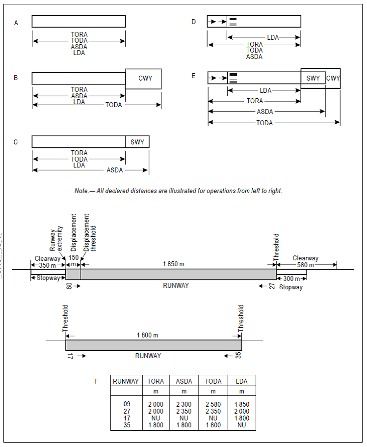
Figure GM-B-1. Illustration of declared distances
[Issue: ADR-DSN/3]
CS ADR-DSN.B.040 Runways with stopways or clearways
ED Decision 2014/013/R
The length(s) of a stopway or clearway, where provided, should be of adequate distance to meet the operational requirements for the aircraft which the runway is intended to serve.
GM1 ADR-DSN.B.040 Runways with stopways, or clearways
ED Decision 2014/013/R
Where a runway is associated with a stopway or clearway, an actual runway length less than that resulting from application of GM1 ADR-DSN.B.035 as appropriate, may be considered satisfactory but, in such a case, any combination of runway, stopway, and clearway provided should permit compliance with the operational requirements for take-off and landing of the aeroplanes the runway is intended to serve.
CS ADR-DSN.B.045 Width of runways
ED Decision 2017/021/R
(a)The width of a runway should be not less than the appropriate dimension specified in the Table B-1.
Code number | Outer Main Gear Wheel Span (OMGWS) | |||
Up to but not including 4.5 m | 4.5 m up to but not including 6 m | 6 m up to but not including 9 m | 9 m up to but not including 15 m | |
1a | 18 m | 18 m | 23 m | — |
2a | 23 m | 23 m | 30 m | — |
3 | 30 m | 30 m | 30 m | 45 m |
4 | — | — | 45 m | 45 m |
aThe width of a precision approach runway should be not less than 30 m where the code number is 1 or 2. | ||||
Table B-1. Width of runway
(b)The width of the runway should be measured at the outside edge of the runway side stripe marking where provided, or the edge of the runway.
[Issue: ADR-DSN/4]
GM1 ADR-DSN.B.045 Width of runways
ED Decision 2017/021/R
(a)The combinations of code numbers and OMGWSs for which widths are specified have been developed for typical aeroplane characteristics.
(b)Factors affecting runway width are given in ICAO Doc 9157, Aerodrome Design Manual, Part 1, Runways.
(c)See CS ADR-DSN.B.125 to CS ADR-DSN.B.145 concerning the provision of runway shoulders, in particular for code F aeroplanes with four (or more) engines.
[Issue: ADR-DSN/3]
[Issue: ADR-DSN/4]
CS ADR-DSN.B.050 Minimum distance between parallel non-instrument runways
ED Decision 2014/013/R
(a)Where parallel non-instrument runways are intended for simultaneous use, the minimum distance between their centre lines should be:
(1)210 m where the higher code number is 3 or 4;
(2)150 m where the higher code number is 2; and
(3)120 m where the higher code number is 1.
GM1 ADR-DSN.B.050 Minimum distance between parallel non-instrument runways
ED Decision 2014/013/R
(a)Except that for independent parallel approaches, combinations of minimum distances and associated conditions other than those specified in the PANS-ATM (Doc 4444) may be applied when it is determined that such combinations would not adversely affect the safety of aircraft operations.
(b)Procedures for wake turbulence categorisation of aircraft and wake turbulence separation minima are contained in the Procedures for Air Navigation Services — Air Traffic Management (PANS-ATM), Doc 4444, Chapter 4, 4.9 and Chapter 5, 5.8, respectively.
CS ADR-DSN.B.055 Minimum distance between parallel instrument runways
ED Decision 2016/027/R
(a)Where parallel instrument runways are intended for simultaneous use, the minimum distance between their centre lines should be:
(1)1 035 m for independent parallel approaches;
(2)915 m for dependent parallel approaches;
(3)760 m for independent parallel departures; and
(4)760 m for segregated parallel operations.
(b)Apart from provided in (a) above, for segregated parallel operations the specified minimum distance:
(1)may be decreased by 30 m for each 150 m that the arrival runway is staggered toward the arriving aircraft, to a minimum of 300 m; and
(2)should be increased by 30 m for each 150 m that the arrival runway is staggered away from the arriving aircraft.
(c)Other combinations of minimum distances should apply taking into account ATM and operational aspects.
[Issue: ADR-DSN/3]
GM1 ADR-DSN.B.055 Minimum distance between parallel instrument runways
ED Decision 2016/027/R
Guidance on procedures and facilities requirements for simultaneous operations on parallel or near-parallel instrument runways are contained in ICAO, PANS-ATM, Doc 4444, Chapter 6 and ICAO, PANS-OPS, Doc 8168, Volume I, Part III, Section 2, and Volume II, Part I, Section 3; Part II, Section 1; and Part III, Section 3, and relevant guidance is contained in ICAO Doc, 9643, Manual on Simultaneous Operations on Parallel or Near-Parallel Instrument Runways (SOIR).
[Issue: ADR-DSN/3]
CS ADR-DSN.B.060 Longitudinal slopes of runways
ED Decision 2016/027/R
(a)The safety objective of limiting the longitudinal runway slope is to enable stabilized and safe use of runway by an aircraft.
(b)The slope computed by dividing the difference between the maximum and minimum elevation along the runway centre line by the runway length should not exceed:
(1)1 % where the code number is 3 or 4; and
(2)2 % where the code number is 1 or 2.
(c)Along no portion of a runway should the longitudinal slope exceed:
(1)1.25 % where the code number is 4, except that for the first and last quarter of the length of the runway where the longitudinal slope should not exceed 0.8 %;
(2)1.5 % where the code number is 3, except that for the first and last quarter of the length of a precision approach runway Category II or III where the longitudinal slope should not exceed 0.8 %; and
(3)2 % where the code number is 1 or 2.
[Issue: ADR-DSN/3]
GM1 ADR-DSN.B.060 Longitudinal slopes on runways
ED Decision 2017/021/R
Slopes should be so designed as to minimise impact on aircraft and so not to hamper the operation of aircraft. For precision approach runways, slopes in a specified area from the runway end, and including the touchdown area, should be designed so that they should correspond to the characteristics needed for such type of approach.
[Issue: ADR-DSN/4]
CS ADR-DSN.B.065 Longitudinal slope changes on runways
ED Decision 2014/013/R
(a)The safety objective of limiting the longitudinal runway slope changes is to avoid damage of aircraft and to enable safe use of runway by an aircraft.
(b)Where slope changes cannot be avoided, a slope change between two consecutive slopes should not exceed:
(1)1.5 % where the code number is 3 or 4; and
(2)2 % where the code number is 1 or 2.
(c)The transition from one slope to another should be accomplished by a curved surface with a rate of change not exceeding:
(1)0.1 % per 30 m (minimum radius of curvature of 30 000 m) where the code number is 4;
(2)0.2 % per 30 m (minimum radius of curvature of 15 000 m) where the code number is 3; and
(3)0.4 % per 30 m (minimum radius of curvature of 7 500 m) where the code number is 1 or 2.
GM1 ADR-DSN.B.065 Longitudinal slopes changes on runways
ED Decision 2014/013/R
(a)Slope changes are so designed as to reduce dynamic loads on the undercarriage system of the aeroplane. Minimising slope changes is especially important on runways where aircraft move at high speeds.
(b)For precision approach runways, slopes in a specified area from the runway end, and including the touchdown area, are so designed that they should correspond to the characteristics needed for such type of approach.
CS ADR-DSN.B.070 Sight distance for slopes on runways
ED Decision 2014/013/R
(a)The safety objective of minimum runway sight distance values is to achieve the necessary visibility to enable safe use of runway by an aircraft.
(b)Where slope changes on runways cannot be avoided, they should be such that there should be an unobstructed line of sight from:
(1)any point 3 m above a runway to all other points 3 m above the runway within a distance of at least half the length of the runway where the code letter is C, D, E, or F;
(2)any point 2 m above a runway to all other points 2 m above the runway within a distance of at least half the length of the runway where the code letter is B; and
(3)any point 1.5 m above a runway to all other points 1.5 m above the runway within a distance of at least half the length of the runway where the code letter is A.
GM1 ADR-DSN.B.070 Sight distance for slopes of runways
ED Decision 2022/006/R
(a)Runway longitudinal slopes and slopes changes are so designed that the pilot in the aircraft has an unobstructed line of sight over all or as much of the runway as possible, thereby enabling him to see aircraft or vehicles on the runway, and to be able to manoeuvre and take avoiding action.
(b)Consideration will have to be given to providing an unobstructed line of sight over the entire length of a single runway where a full-length parallel taxiway is not available. Where an aerodrome has intersecting runways, additional criteria on the line of sight of the intersection area needs to be considered for operational safety. Additional guidance is given in ICAO Doc 9157, Aerodrome Design Manual, Part 1, Runways.
[Issue: ADR-DSN/3]
[Issue: ADR-DSN/6]
CS ADR-DSN.B.075 Distance between slope changes on runways
ED Decision 2014/013/R
Undulations or appreciable changes in slopes located close together along a runway should be avoided. The distance between the points of intersection of two successive curves should not be less than:
(a)the sum of the absolute numerical values of the corresponding slope changes multiplied by the appropriate value as follows:
(1)30 000 m where the code number is 4;
(2)15 000 m where the code number is 3; and
(3)5 000 m where the code number is 1 or 2; or
(b)45 m;
whichever is greater.
GM1 ADR-DSN.B.075 Distance between slope changes on runways
ED Decision 2014/013/R
The following example illustrates how the distance between slope changes is to be determined (see Figure GM-B-2):
D for a runway where the code number is 3 should be at least:
15 000 (│x – y│ + │y – z│) m
│x – y│ being the absolute numerical value of x – y
│y – z│ being the absolute numerical value of y – z
Assuming x = +0.01
y = –0.005
z = +0.005
then │x – y│ = 0.015
then │y – z│ = 0.01
To comply with the specifications, D should be not less than:
15 000 (0.015 + 0.01) m,
that is, 15 000 × 0.025 = 375 m
When a runway is planned that should combine the extreme values for the slopes and changes in slope permitted, as prescribed in CS ADR-DSN.B.060 to CS ADR-DSN.B.080, a study should be made to ensure that the resulting surface profile should not hamper the operation of aeroplanes.
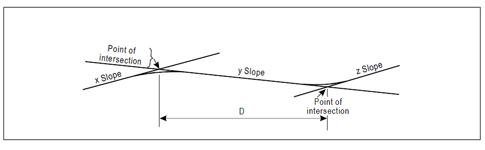
Figure GM-B-2. Profile on centre line of runway
CS ADR-DSN.B.080 Transverse slopes on runways
ED Decision 2014/013/R
(a)The safety objective of runway transverse slopes is to promote the most rapid drainage of water from the runway.
(b)To promote the most rapid drainage of water, the runway surface should be cambered, except where a single crossfall from high to low in the direction of the wind most frequently associated with rain would ensure rapid drainage. The transverse slope should be:
(1)not less than 1 % and not more than 1.5 % where the code letter is C, D, E or F; and;
(2)not less than 1 % and not more than 2 % where the code letter is A or B;
except at runway or taxiway intersections where flatter slopes may be necessary.
(c)For a cambered surface, the transverse slope on each side of the centre line should be symmetrical.
(d)The transverse slope should be substantially the same throughout the length of a runway except at an intersection with another runway or a taxiway where an even transition should be provided taking account of the need for adequate drainage.
GM1 ADR-DSN.B.080 Transverse slopes on runways
ED Decision 2017/021/R
The slopes on a runway are intended to prevent the accumulation of water (or possible fluid contaminant) on the surface and to facilitate rapid drainage of surface water (or possible fluid contaminant). The water (or possible fluid contaminant) evacuation is facilitated by an adequate combination of longitudinal and transverse slopes, and may also be assisted by grooving the runway surface.
[Issue: ADR-DSN/4]
CS ADR-DSN.B.085 Runway strength
ED Decision 2014/013/R
The runway should be of sufficient strength to support normal operations of the most demanding aircraft without risk of damage either to the aeroplane or the runway.
GM1 ADR-DSN.B.085 Runway strength
ED Decision 2022/006/R
(a)Additional information on the bearing strength, the design and evaluation of pavements is given in ICAO Doc 9157, Aerodrome Design Manual, Part 3, Pavements.
(b)The method for reporting the bearing strength of the pavement is available in Part-ADR.OPS of Regulation (EU) No 139/2014.
[Issue: ADR-DSN/3]
[Issue: ADR-DSN/6]
CS ADR-DSN.B.090 Surface of runways
ED Decision 2016/027/R
(a)The surface of a runway should be constructed without irregularities that would impair the runway surface friction characteristics or otherwise adversely affect the take-off or landing of an aeroplane.
(b)A paved runway should be so constructed or resurfaced as to provide surface friction characteristics at or above the minimum friction level.
(c)The average surface texture depth of a new surface should be not less than 1.0 mm.
(d)When the surface is grooved or scored, the grooves or scorings should be either perpendicular to the runway centre line or parallel to non-perpendicular transverse joints where applicable.
[Issue: ADR-DSN/3]
GM1 ADR-DSN.B.090 Surface of runways
ED Decision 2016/027/R
(a)In adopting tolerances for runway surface irregularities, the following standard of construction is achievable for short distances of 3 m and conform to good engineering practice: except across the crown of a camber or across drainage channels, the finished surface of the wearing course is to be of such regularity that when tested with a 3 m straight-edge placed anywhere in any direction on the surface, there is no deviation greater than 3 mm between the bottom of the straight-edge and the surface of the pavement anywhere along the straight-edge.
(b)Caution should also be exercised when inserting runway lights or drainage grilles in runway surfaces to ensure that adequate smoothness of the surface is maintained.
(c)Additional guidance on surface of runways is given in ICAO Doc 9157, Aerodrome Design Manual, Part 3, Pavements.
(d)Macrotexture and microtexture should be taken into consideration in order to provide the required surface friction characteristics. Additional guidance is given in GM1 ADR-DSN.B.191. Additional guidance on design and methods for improving runway surface texture is given in ICAO Doc 9157, Aerodrome Design Manual, Part 3, Pavements.
(e)The surface of a paved runway should be evaluated when constructed or resurfaced to determine that the surface friction characteristics achieve the design objectives.
[Issue: ADR-DSN/3]
CS ADR-DSN.B.095 Runway turn pads
ED Decision 2017/021/R
(a)The safety objective of the runway turn pad is to facilitate a safe 180-degree turn by aeroplanes on runway ends that are not served by a taxiway or taxiway turnaround.
(b)Where the end of a runway is not served by a taxiway or a taxiway turnaround, and if required, a runway turn pad should be provided to facilitate a 180-degree turn of aeroplanes.
(c)The design of a runway turn pad should be such that when the cockpit of the most demanding aircraft for which the turn pad is intended remains over the turn pad marking, the clearance distance between any wheel of the aeroplane landing gear and the edge of the turn pad should be not less than that given by the following tabulation:
Clearance | Outer Main Gear Wheel Span (OMGWS) | |||
Up to but not including 4.5 m | 4.5 m up to but not including 6 m | 6 m up to but not including 9 m | 9 m up to but not including 15 m | |
1.50 m | 2.25 m | 3 ma or 4 mb | 4 m | |
a if the turn pad is intended to be used by aeroplanes with a wheel base less than 18 m. b if the turn pad is intended to be used by aeroplanes with a wheel base equal to or greater than 18 m. | ||||
Note: Wheel base means the distance from the nose gear to the geometric centre of the main gear. | ||||
(d)The runway turn pad should be located on either the left or right side of the runway and adjoining the runway pavement at both ends of the runway and at some intermediate locations where deemed necessary.
(e)The intersection angle of the runway turn pad with the runway should not exceed 30 degrees.
(f)The nose wheel steering angle to be used in the design of the runway turn pad should not exceed 45 degrees.
[Issue: ADR-DSN/4]
GM1 ADR-DSN.B.095 Runway turn pads
ED Decision 2022/006/R
Where severe weather conditions and resultant lowering of surface friction characteristics prevail, a larger wheel-to-edge clearance should be provided.
(a)A typical runway turn pad layout is presented in Figure GM-B-3 below:
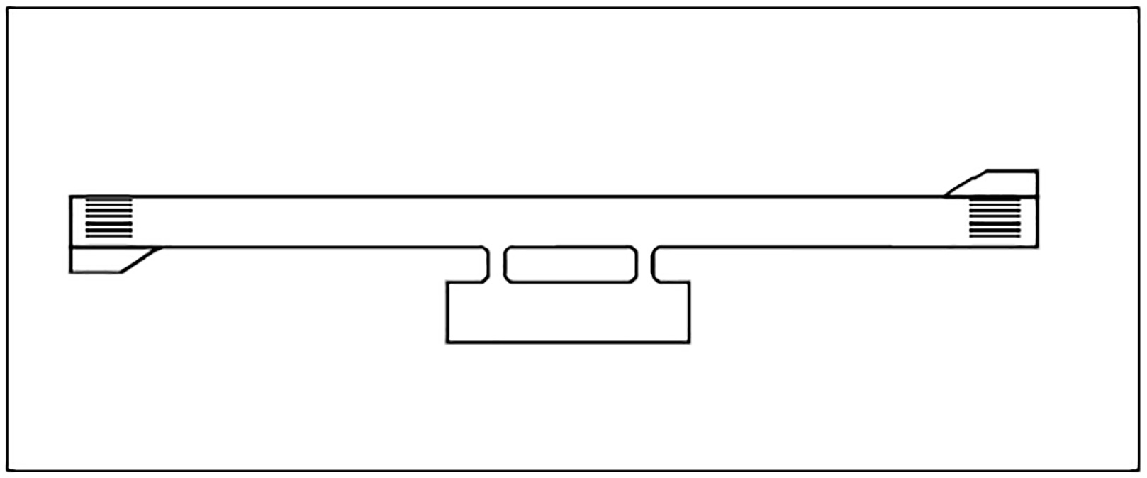
Figure GM-B-3. Typical turn pad layout
(b)Such areas, if provided along a runway, may also be useful to reduce taxiing time and distance for aeroplanes which may not require the full length of the runway.
(c)Additional guidance on the design of runway turn pads is given in ICAO Doc 9157, Aerodrome Design Manual, Part 1, Runways.
[Issue: ADR-DSN/3]
[Issue: ADR-DSN/4]
[Issue: ADR-DSN/6]
CS ADR-DSN.B.100 Slopes on runway turn pads
ED Decision 2014/013/R
The longitudinal and transverse slopes on a runway turn pad should be sufficient to prevent the accumulation of water on the surface and facilitate rapid drainage of surface water. The slopes should be the same as those on the adjacent runway pavement surface.
GM1 ADR-DSN.B.100 Slopes on runway turn pads
ED Decision 2014/013/R
Slopes should be so designed as to minimise impact on aircraft and so not to hamper the operation of aircraft.
CS ADR-DSN.B.105 Strength of runway turn pads
ED Decision 2014/013/R
The strength of a runway turn pad should be compatible with the adjoining runway which it serves, due consideration being given to the fact that the turn pad should be subjected to slow-moving traffic making hard turns and consequent higher stresses on the pavement.
GM1 ADR-DSN.B.105 Strength of runway turn pads
ED Decision 2014/013/R
intentionally left blank
CS ADR-DSN.B.110 Surface of runway turn pads
ED Decision 2016/027/R
(a)The surface of a runway turn pad should not have surface irregularities that may cause damage to an aeroplane using the turn pad.
(b)The surface of a runway turn pad should be so constructed or resurfaced as to provide surface friction characteristics at least equal to that of the adjoining runway.
[Issue: ADR-DSN/3]
GM1 ADR-DSN.B.110 Surface of runway turn pads
ED Decision 2014/013/R
intentionally left blank
CS ADR-DSN.B.115 Width of shoulders for runway turn pads
ED Decision 2022/006/R
The runway turn pads should be provided with shoulders of such width as is necessary to prevent surface erosion by the jet blast of the most demanding aeroplane for which the turn pad is intended and any possible foreign object damage to the aeroplane engines.
[Issue: ADR-DSN/6]
GM1 ADR-DSN.B.115 Width of shoulders for runway turn pads
ED Decision 2022/006/R
As a minimum, the width of the shoulders would need to cover the outer engine of the most demanding aeroplane and thus may be wider than the associated runway shoulders.
[Issue: ADR-DSN/6]
CS ADR-DSN.B.120 Strength of shoulders for runway turn pads
ED Decision 2014/013/R
The strength of runway turn pad shoulders should be capable of withstanding the occasional passage of the most demanding aircraft it is designed to serve without inducing structural damage to the aircraft and to the supporting ground vehicles that may operate on the shoulder.
GM1 ADR-DSN.B.120 Strength of shoulders for runway turn pads
ED Decision 2014/013/R
intentionally left blank
CS ADR-DSN.B.125 Runway shoulders
ED Decision 2022/006/R
(a)The safety objective of a runway shoulder is that it should be so constructed as to mitigate any hazard to an aircraft running off the runway or stopway or to avoid the ingestion of loose stones or other objects by turbine engines.
(b)Runway shoulders should be provided for a runway where the code letter is D, E or F, for aeroplanes with an OMGWS from 9 m up to but not including 15 m.
(c)Runway shoulders need not be provided where the runway width is 60 m, for aeroplanes with an OMGWS from 9 m up to but not including 15 m and code letter:
(1)D, E; or
(2)F with two or three engines.
(d)Where the runway width is 60 m, for aeroplanes with an OMGWS from 9 m up to but not including 15 m and code letter F with four (or more) engines, only the portion of runway shoulders between the runway edge up to a distance as prescribed in paragraph (c) of CS ADRDSN.B.135 should be provided.
[Issue: ADR-DSN/4]
[Issue: ADR-DSN/6]
GM1 ADR-DSN.B.125 Runway shoulders
ED Decision 2017/021/R
(a)Runway shoulders should be considered because strong crosswinds may result in significant deviation from the runway centre line. In the case of some large aircraft, the wing-mounted engines may overhang the runway edge and there is a risk of jet blast eroding the surface adjacent to the runway. This can cause dust and the possible ingestion of debris by the engines.
(b)Further guidance on runway shoulders is given in ICAO Doc 9157, Aerodrome Design Manual, Part 1, Runways.
(c)Mitigation measures that can be considered are to provide the runway with inset runway edge lights (in lieu of elevated lights, to protect aeroplane from ingestion) and additional runway centre line guidance.
[Issue: ADR-DSN/3]
[Issue: ADR-DSN/4]
CS ADR-DSN.B.130 Slopes on runway shoulders
ED Decision 2014/013/R
(a)The safety objective of runway shoulder transverse slopes is to promote the most rapid drainage of water from the runway and runway shoulder.
(b)The surface of the paved shoulder that abuts the runway should be flush with the surface of the runway and its transverse slope should not exceed 2.5 %.
GM1 ADR-DSN.B.130 Slopes on runway shoulders
ED Decision 2014/013/R
intentionally left blank
CS ADR-DSN.B.135 Width of runway shoulders
ED Decision 2017/021/R
For aeroplanes with an OMGWS from 9 m up to but not including 15 m the runway shoulders should extend symmetrically on each side of the runway so that the overall width of the runway and its shoulders is not less than:
(a)60 m where the code letter is D or E;
(b)60 m where the code letter is F with two- or three-engined aeroplanes; and
(c)75 m where the code letter is F with four (or more) engined aeroplanes.
[Issue: ADR-DSN/3]
[Issue: ADR-DSN/4]
GM1 ADR-DSN.B.135 Width of runway shoulders
ED Decision 2014/013/R
intentionally left blank
CS ADR-DSN.B.140 Strength of runway shoulders
ED Decision 2017/021/R
The portion of a runway shoulder between the runway edge and a distance of 30 m from the runway centre line should be prepared or constructed so as to be capable, in the event of an aeroplane running off the runway, of supporting the aeroplane without inducing structural damage to the aeroplane and of supporting ground vehicles which may operate on the shoulder.
[Issue: ADR-DSN/4]
GM1 ADR-DSN.B.140 Strength of runway shoulders
ED Decision 2017/021/R
(a)Runway shoulders should be so prepared as to be capable of supporting the aeroplanes using the runway without causing structural damage to those aeroplanes. They should also be capable of supporting vehicles such as firefighting appliances. In some cases, whilst the bearing strength of the natural ground may be sufficient, special preparation may be necessary to avoid erosion and the possible ingestion of debris by engines.
(b)Guidance on characteristics and treatment of runway shoulders:
(1)The shoulder of a runway or stopway should be prepared or constructed so as to support an aeroplane and minimise any hazard to an aeroplane running off the runway or stopway. Some guidance is given in the following paragraphs on certain special problems which may arise, and on further measures to avoid the ingestion of loose stones or other objects by turbine engines.
(2)In some cases, the bearing strength of the natural ground in the strip may be sufficient, without special preparation, to meet the requirements for shoulders. Where special preparation is necessary, the method used should depend on local soil conditions and on the mass of the aeroplanes the runway is intended to serve. Soil tests should help in determining the best method of improvement (e.g. drainage, stabilisation, surfacing and light paving).
(c)Attention should also be paid when designing shoulders to prevent the ingestion of stones or other objects by turbine engines. Similar considerations apply here to those discussed for the margins of taxiways both as to the special measures that may be necessary and as to the distance over which such special measures, if required, should be taken. Further guidance is given in ICAO Doc 9157, Aerodrome Design Manual, Part 1 Runways, and Part 2, Taxiways, Aprons and Holding Bays.
(d)Where shoulders have been treated specially, either to provide the required bearing strength or to prevent the presence of stones or debris, difficulties may arise because of a lack of visual contrast between the runway surface and that of the adjacent strip. Such difficulties can be overcome either by providing a good visual contrast between the surfacing of the runway and of the strip, or by providing a runway side stripe marking.
(e)Additional guidance on strength of runway shoulders is given in ICAO Doc 9157, Aerodrome Design Manual, Part 1, Runways.
[Issue: ADR-DSN/3]
[Issue: ADR-DSN/4]
CS ADR-DSN.B.145 Surface of runway shoulders
ED Decision 2017/021/R
(a)The surface of a runway shoulder should be prepared or constructed so as to resist erosion and prevent the ingestion of the surface material by aeroplane engines.
(b)Runway shoulders for code letter F aeroplanes should be paved to a minimum overall width of runway and shoulder of not less than 60 m.
[Issue: ADR-DSN/4]
GM1 ADR-DSN.B.145 Surface of runway shoulders
ED Decision 2017/021/R
(a)Where a runway shoulder is not paved, additional surface treatment or inspections may be necessary, especially for runways that accept operations by 4-engined aircraft with a code letter D or larger.
(b)Shoulders for runways where the code letter is E normally should be paved.
(c)If movements of 4-engined aircraft with a code letter D take place, the need for fully paved width shoulders should be assessed by local hazard analysis. Where the runway shoulder is not paved, it may be possible to contain the risk from erosion or from the ingestion of debris. In such cases:
(1)The runway shoulder should be stabilised and the ground is prepared so that there is full grass coverage with no loose gravel or other material. This may include additional materials if the bearing strength and surface of the ground are not sufficient.
(2)A programme of inspections of the shoulders and runway may be implemented to confirm their continuing serviceability, and ensure that there is no deterioration that could create a risk of foreign object debris (FOD), or otherwise hazard aircraft operations.
(3)A programme of sweeping may be required before and after movements, should debris be drawn onto the runway surface.
(d)Additional guidance on surface of runway shoulders is given in ICAO Doc 9157, Aerodrome Design Manual, Part 1, Runways.
[Issue: ADR-DSN/4]
CS ADR-DSN.B.150 Runway strip to be provided
ED Decision 2017/021/R
(a)The safety objective of the runway strip is to reduce the risk of damage to an aircraft accidentally running off the runway, to protect aircraft flying over it when taking-off or landing, and to enable safe use by rescue and firefighting (RFF) vehicles.
(b)A runway and any associated stopways should be included in a strip.
[Issue: ADR-DSN/4]
GM1 ADR-DSN.B.150 Runway strip to be provided
ED Decision 2022/006/R
(a)A runway strip extends laterally to a specified distance from the runway centre line, longitudinally before the threshold, and beyond the runway end. It provides an area clear of objects that may endanger aeroplanes. Any equipment or installation required for air navigation or for aircraft safety purposes and is located in this object-free area should be frangible and mounted as low as possible. The term ‘aircraft safety purposes’ refers to the installation of arresting systems.
(b)When the threshold or end of the landing distance do not coincide with the ends of a runway, the runway strip enclosing the runway and any associated stopway should extend to the lengths specified in CS ADR-DSN.B.155 at the widths specified in CS ADR-DSN.B.160, based on the threshold, end of landing distance or end of stopway, as appropriate.
[Issue: ADR-DSN/4]
[Issue: ADR-DSN/6]
CS ADR-DSN.B.155 Length of runway strip
ED Decision 2016/027/R
(a)A strip should extend before the threshold and beyond the end of the runway or stopway for a distance of at least:
(1)60 m where the code number is 2, 3, or 4;
(2)60 m where the code number is 1 and the runway is an instrument one; and
(3)30 m where the code number is 1 and the runway is a non-instrument one.
[Issue: ADR-DSN/3]
GM1 ADR-DSN.B.155 Length of runway strip
ED Decision 2014/013/R
intentionally left blank
CS ADR-DSN.B.160 Width of runway strip
ED Decision 2017/021/R
(a)A strip including a precision approach runway should extend laterally to a distance of at least:
(1)140 m where the code number is 3 or 4; and
(2)70 m where the code number is 1 or 2;
on each side of the centre line of the runway and its extended centre line throughout the length of the strip.
(b)A strip including a non-precision approach runway should extend laterally to a distance of at least:
(1)140 m where the code number is 3 or 4; and
(2)70 m where the code number is 1 or 2;
on each side of the centre line of the runway and its extended centre line throughout the length of the strip.
(c)A strip including a non-instrument runway should extend on each side of the centre line of the runway and its extended centre line throughout the length of the strip, to a distance of at least:
(1)75 m where the code number is 3 or 4;
(2)40 m where the code number is 2; and
(3)30 m where the code number is 1.
[Issue: ADR-DSN/4]
GM1 ADR-DSN.B.160 Width of runway strip
ED Decision 2014/013/R
intentionally left blank
CS ADR-DSN.B.165 Objects on runway strips
ED Decision 2021/004/R
(a)An object situated on a runway strip which may endanger aeroplanes should be regarded as an obstacle and should, as far as practicable, be removed.
(b)No fixed object, other than visual aids required for air navigation or those required for aircraft safety purposes and which must be sited on the runway strip, and satisfying the relevant frangibility requirement in Chapter T, should be permitted on a runway strip:
(1)within 77.5 m of the runway centre line of a precision approach runway Category I, II or III where the code number is 4 and the code letter is F; or
(2)within 60 m of the runway centre line of a precision approach runway Category I, II or III where the code number is 3 or 4; or
(3)within 45 m of the runway centre line of a precision approach runway Category I where the code number is 1 or 2.
(c)To eliminate a buried vertical surface on objects situated on a graded portion of the runway strip, a slope should be provided to minimise hazards to aeroplanes running off the runway.
[Issue: ADR-DSN/3]
[Issue: ADR-DSN/5]
GM1 ADR-DSN.B.165 Objects on runway strips
ED Decision 2022/006/R
(a)Within the graded portion of the runway strip, measures should be taken to prevent an aeroplane’s wheel when sinking into the ground, from striking a hard vertical face. Special problems may arise for runway light fittings or other objects mounted in the strip or at the intersection with a taxiway or another runway. In the case of constructions within the graded portion of the runway strip, such as intersecting runways or taxiways, where the surface should also be flush with the strip surface, they should be delethalised, that is, so constructed as to avoid presenting a buried vertical face to aircraft wheels in soft ground conditions in any direction from which an aircraft is likely to approach. A vertical face can be eliminated by chamfering from the top of those constructions to not less than 30 cm below the strip surface level. Other objects situated within the graded portion of the runway strip, the functions of which do not require them to be at surface level, should be buried to a depth of not less than 30 cm. Where this is not feasible, to eliminate a buried vertical surface, a slope should be provided which extends from the top of the construction to not less than 30 cm below ground level. The slope can be created by using a mixture of compacted gravel or asphalt or crushed aggregates and soil.
(b)Consideration should be given to the location and design of drains on a runway strip to prevent damage to an aeroplane accidentally running off a runway. Suitably designed drain covers may be required.
(c)Guidance on the design of drain covers is given in ICAO Doc 9157, Aerodrome Design Manual, Part 1, Runways.
(d)Where open-air or covered storm water conveyances are installed, consideration should be given in order to ensure that their structure does not extend above the surrounding ground so as not to be considered an obstacle.
(e)Particular attention needs to be given to the design and maintenance of an open-air storm water conveyance in order to prevent wildlife attraction, in particular birds. The open-air storm water conveyance may be covered by a net, if required. Further guidance is given in ICAO Doc 9137, Airport Services Manual, Part 3, Wildlife Control and Reduction.
(f)The term ‘aircraft safety purposes’ refers to the installation of arresting systems.
[Issue: ADR-DSN/3]
[Issue: ADR-DSN/4]
[Issue: ADR-DSN/6]
CS ADR-DSN.B.170
ED Decision 2014/013/R
intentionally left blank
GM1 ADR-DSN.B.170
ED Decision 2014/013/R
intentionally left blank
CS ADR-DSN.B.175 Grading of runway strips
ED Decision 2017/021/R
(a)That portion of a strip of an instrument runway within a distance of at least:
(1)75 m where the code number is 3 or 4; and
(2)40 m where the code number is 1 or 2;
from the centre line of the runway and its extended centre line should provide a graded area for aeroplanes which the runway is intended to serve in the event of an aeroplane running off the runway.
(b)That portion of a strip of a non-instrument runway within a distance of at least:
(1)75 m where the code number is 3 or 4;
(2)40 m where the code number is 2; and
(3)30 m where the code number is 1;
from the centre line of the runway and its extended centre line should provide a graded area for aeroplanes which the runway is intended to serve in the event of an aeroplane running off the runway.
(c)The surface of that portion of a strip that abuts a runway, shoulder, or stopway should be flush with the surface of the runway, shoulder, or stopway.
(d)That portion of a strip to at least 30 m before the start of a runway should be prepared against blast erosion in order to protect a landing aeroplane from the danger of an exposed edge.
[Issue: ADR-DSN/4]
GM1 ADR-DSN.B.175 Grading of runway strips
ED Decision 2022/006/R
(a)For a precision approach runway, where the code number is 3 or 4, it may be desirable a greater width of that portion of a strip to be graded should be considered. Figure GM-B-4 shows the shape and dimensions of a wider strip that may be considered for such a runway. This strip has been designed using information on aircraft running off runways. The portion to be graded extends to a distance of 105 m from the centre line, except that the distance is gradually reduced to 75 m from the centre line at both ends of the strip, for a length of 150 m from the runway end.
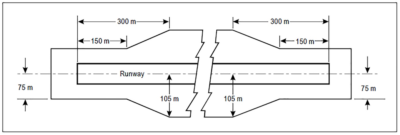
Figure GM-B-4. Graded portion of a strip including a precision approach runway where the code number is 3 or 4
(b)Where the areas in paragraph (a) above have paved surface, they should be able to withstand the occasional passage of the critical aeroplane for runway pavement design.
(c)Additional guidance on grading is given in ICAO Doc 9157, Aerodrome Design Manual Part 1, Runways.
(d)The area adjacent to the end of a runway provided to reduce the erosive effects of jet blast and propeller wash may be referred to as a blast pad.
(e)Guidance on protection against aeroplane engine blast is given in ICAO Doc 9157, Aerodrome Design Manual, Part 2.
[Issue: ADR-DSN/3]
[Issue: ADR-DSN/4]
[Issue: ADR-DSN/6]
CS ADR-DSN.B.180 Longitudinal slopes on runway strips
ED Decision 2014/013/R
(a)The safety objective of longitudinal runway strip slope is to define maximum gradient values that should not interfere with the safe use of the runway strip by an aircraft.
(b)A longitudinal slope along that portion of a strip to be graded should not exceed:
(1)1.5 % where the code number is 4;
(2)1.75 % where the code number is 3; and
(3)2 % where the code number is 1 or 2.
(c)Longitudinal slope changes on that portion of a strip to be graded should be as gradual as practicable, and abrupt changes or sudden reversals of slopes should be avoided.
GM1 ADR-DSN.B.180 Longitudinal Slopes on runway strips
ED Decision 2014/013/R
intentionally left blank
CS ADR-DSN.B.185 Transverse slopes on runway strips
ED Decision 2014/013/R
(a)Transverse slopes on that portion of a strip to be graded should be adequate to prevent the accumulation of water on the surface but should not exceed:
(1)2.5 % where the code number is 3 or 4; and
(2)3 % where the code number is 1 or 2;
except that to facilitate drainage from the slope for the first 3 m outward from the runway, shoulder or stopway edge should be negative as measured in the direction away from the runway and may be as great as 5 %.
(b)The transverse slopes of any portion of a strip beyond that to be graded should not exceed an upward slope of 5 % as measured in the direction away from the runway.
GM1 ADR-DSN.B.185 Transverse slopes on runway strips
ED Decision 2017/021/R
(a)Where required for proper drainage, an open-air storm water conveyance may be allowed in the non-graded portion of a runway strip and should be placed as far as practicable from the runway.
(b)The aerodrome RFF procedure should take into account the location of open-air storm water conveyances within the non-graded portion of a runway strip.
[Issue: ADR-DSN/4]
CS ADR-DSN.B.190 Strength of runway strips
ED Decision 2014/013/R
(a)That portion of a strip of an instrument runway within a distance of at least:
(1)75 m where the code number is 3 or 4; and
(2)40 m where the code number is 1 or 2;
from the centre line of the runway and its extended centre line should be prepared or constructed so as to minimise hazards arising from differences in load-bearing capacity to aeroplanes which the runway is intended to serve in the event of an aeroplane running off the runway.
(b)That portion of a strip containing a non-instrument runway within a distance of at least:
(1)75 m where the code number is 3 or 4;
(2)40 m where the code number is 2; and
(3)30 m where the code number is 1;
from the centre line of the runway and its extended centre line should be prepared or constructed so as to minimise hazards arising from differences in load-bearing capacity to aeroplanes which the runway is intended to serve in the event of an aeroplane running off the runway.
GM1 ADR-DSN.B.190 Strength of runway strips
ED Decision 2016/027/R
Since the graded portion of a strip is provided to minimise the hazard to an aircraft running off the runway, it should grant sufficient strength in such a manner as to prevent the collapse of the nose landing gear of the aircraft. The surface should be prepared in such a manner as to provide drag to an aircraft and below the surface, it should have sufficient bearing strength to avoid damage to the aircraft. To meet these divergent needs, the following guidelines are provided for preparing the strip. It is noted, that a depth of 15 cm is a depth to which the nose gear may sink without collapsing. Therefore, it is recommended that the soil at a depth of 15 cm below the finished strip surface should be prepared to have a sufficient stability, demonstrated by bearing strength of California Bearing Ratio (CBR) value of 15 to 20. The intention of this is to prevent the nose gear from damage. The top 15 cm may be of lesser strength which would facilitate deceleration of aircraft. There are also other methods for soil investigation. In case of a deeper sinking than 15 cm, the maximum wheel sinking without collapsing should be examined by using different methods of soil investigation.
[Issue: ADR-DSN/3]
CS ADR-DSN.B.191 Drainage characteristics of the movement area and adjacent areas
ED Decision 2016/027/R
The safety objective of the drainage systems of the movement area and adjacent areas is to minimise water depth on the surface by draining surface water off the runway in the shortest path practicable and particularly out of the area of the wheel path.
[Issue: ADR-DSN/3]