
Filters
GM1 ADR-DSN.B.191 Drainage characteristics of the movement area and adjacent areas
ED Decision 2016/027/R
(a)Rapid drainage of surface water is a primary safety consideration in the design, construction and maintenance of movement area and adjacent areas.
(b)There are two distinct drainage processes:
(1)natural drainage of the surface water from the top of the pavement surface until it reaches the final recipient such as rivers or other water bodies; and
(2)dynamic drainage of the surface water trapped under a moving tire until it reaches outside the tire-to-ground contact area.
Both drainage processes can be controlled through design, construction and maintenance of the pavements in order to prevent accumulation of water on the pavement surface.
(c)Surface drainage is a basic requirement and serves to minimise water depth on the surface. Adequate surface drainage is provided primarily by an appropriately sloped surface (in both the longitudinal and transverse directions). The resulting combined longitudinal and transverse slope is the path for the drainage runoff. This path can be shortened by adding transverse grooves.
(d)Dynamic drainage is achieved through built-in texture in the pavement surface. The rolling tire builds up water pressure and squeezes the water out the escape channels provided by the texture. The dynamic drainage of the tire-to-ground contact area may be improved by adding transverse grooves provided that they are subject to rigorous maintenance.
(e)Through construction, the drainage characteristics of the surface are built into the pavement. These surface characteristics are:
(1)Slopes;
(2)Texture:
(i)Microtexture;
(ii)Macrotexture.
(f)Slopes for the various parts of the movement area and adjacent parts are described in Chapters B to G and figures are given as per cent. Further guidance is given in ICAO Doc 9157, Aerodrome Design Manual, Part 1, Runways, Chapter 5.
(g)Texture in the literature is described as microtexture or macrotexture. These terms are understood differently in various part of the aviation industry.
(h)Microtexture is the texture of the individual stones and is hardly detectable by the eye. Microtexture is considered a primary component in skid resistance at slow speeds. On a wet surface at higher speeds a water film may prevent direct contact between the surface asperities and the tire due to insufficient drainage from the tire-to-ground contact area. Microtexture is a built-in quality of the pavement surface. By specifying crushed material that will withstand polishing microtexture, drainage of thin water films are ensured for a longer period of time. Resistance against polishing is expressed in terms of the polished stone values (PSV) which is in principle a value obtained from a friction measurement in accordance with international standards. These standards define the PSV minima that will enable a material with a good microtexture to be selected. A major problem with microtexture is that it can change within short time periods without being easily detected. A typical example of this is the accumulation of rubber deposits in the touchdown area which will largely mask microtexture without necessarily reducing macrotexture.
(k)Macrotexture is the texture among the individual stones. This scale of texture may be judged approximately by the eye. Macrotexture is primarily created by the size of aggregate used or by surface treatment of the pavement and is the major factor influencing drainage capacity at high speeds. Materials should be selected so as to achieve good macrotexture.
(l)The primary purpose of grooving a runway surface is to enhance surface drainage. Natural drainage can be slowed down by surface texture, but grooving can speed up the drainage by providing a shorter drainage path and increasing the drainage rate.
(m)For measurement of macrotexture, simple methods such as the ‘sand and grease patch’ methods described in ICAO Doc 9137, Airport Services Manual, Part 2, Pavement Surface Conditions were developed. These methods were used for the early research on which current airworthiness requirements are based and which refer to a classification categorising macrotexture from A to E. This classification was developed, using sand or grease patch measuring techniques, and issued in 1971 by the Engineering Sciences Data Unit (ESDU).
Runway classification based on texture information from ESDU 71026: | |
Classification | Texture depths (mm) |
A | 0.10 – 0.14 |
B | 0.15 – 0.24 |
C | 0.25 – 0.50 |
D | 0.51 – 1.00 |
E | 1.01 – 2.54 |
(n)Using this classification, the threshold value between microtexture and macrotexture is 0.1 mm mean texture depth (MTD). Related to this scale, the normal wet runway aircraft performance is based upon texture giving drainage and friction qualities midway between classification B and C (0.25 mm). Improved drainage through better texture might qualify for a better aircraft performance class. However, such credit must be in accordance with aeroplane manufacturers’ documentation. Presently credit is given to grooved or porous friction course runways following design, construction and maintenance criteria. The harmonised certification standards of some States refer to texture giving drainage and friction qualities midway between classification D and E (1.0 mm).
(o)For construction, design and maintenance, various international standards are used. Currently ISO 13473-1: ‘Characterization of pavement texture by use of surface profiles — Part 1: Determination of Mean Profile Depth’ links the volumetric measuring technique with non-contact profile measuring techniques giving comparable texture values. These standards describe the threshold value between microtexture and macrotexture as 0.5 mm. The volumetric method has a validity range from 0.25 to 5 mm MTD. The profilometry method has a validity range from 0 to 5 mm mean profile depth (MPD). The values of MPD and MTD differ due to the finite size of the glass spheres used in the volumetric technique and because the MPD is derived from a two-dimensional profile rather than a three-dimensional surface. Therefore, a transformation equation must be established for the measuring equipment used to relate MPD to MTD.
(p)The ESDU scale groups runway surfaces based on macrotexture from A through E, where E represents the surface with best dynamic drainage capacity. The ESDU scale thus reflects the dynamic drainage characteristics of the pavement. Grooving any of these surfaces enhances the dynamic drainage capacity. The resulting drainage capacity of the surface is thus a function of the texture (A through E) and grooving. The contribution from grooving is a function of the size of the grooves and the spacing between the grooves. Aerodromes exposed to heavy or torrential rainfall must ensure that the pavement and adjacent areas have drainage capability to withstand these rainfalls or put limitations on the use of the pavements under such extreme situations. These airports should seek to have the maximum allowable slopes and the use of aggregates providing good drainage characteristics. They should also consider grooved pavements in the E classification to ensure that safety is not impaired.
[Issue: ADR-DSN/3]
CS ADR-DSN.B.195 Clearways
ED Decision 2016/027/R
(a)The inclusion of detailed specifications for clearways below is not intended to imply that a clearway has to be provided.
(b)Location of clearways: The origin of a clearway should be at the end of the take-off run available.
(c)Length of clearways: The length of a clearway should not exceed half the length of the take-off run available.
(d)Width of clearways: A clearway should extend laterally to a distance of at least 75 m on each side of the extended centre line of the runway.
(e)Slopes on clearways: The ground in a clearway should not project above a plane having an upward slope of 1.25 %, the lower limit of this plane being a horizontal line which:
(1)is perpendicular to the vertical plane containing the runway centre line; and
(2)passes through a point located on the runway centre line at the end of the take-off run available.
(f)An object situated on a clearway which may endanger aeroplanes in the air should be regarded as an obstacle and should be removed.
[Issue: ADR-DSN/3]
GM1 ADR-DSN.B.195 Clearways
ED Decision 2014/013/R
(a)Because of transverse or longitudinal slopes on a runway, shoulder, or strip, in certain cases, the lower limit of the clearway plane specified above may be below the corresponding elevation of the runway, shoulder, or strip. It is not intended that these surfaces be graded to conform with the lower limit of the clearway plane, nor is it intended that terrain or objects which are above the clearway plane beyond the end of the strip, but below the level of the strip be removed unless it is considered that they may endanger aeroplanes.
(b)Abrupt upward changes in slope should be avoided when the slope on the ground in a clearway is relatively small or when the mean slope is upward. In such situations, in that portion of the clearway within a distance of 22.5 m or half the runway width whichever is greater, on each side of the extended centre line, the slopes, slope changes, and the transition from runway to clearway should generally conform with those of the runway with which the clearway is associated.
(c)The decision to provide a stopway and/or a clearway as an alternative to an increased length of runway should depend on the physical characteristics of the area beyond the runway end, and on the operating performance requirements of the prospective aeroplanes. The runway, stopway, and clearway lengths to be provided are determined by the aeroplane take-off performance but a check should also be made of the landing distance required by the aeroplanes using the runway to ensure that adequate runway length is provided for landing. The length of a clearway, however, cannot exceed half the length of take-off run available.
(d)The aeroplane performance operating limitations require a length which is enough to ensure that the aeroplane can, after starting a take-off, either be brought safely to a stop or complete the take-off safely. For the purpose of discussion, it is supposed that the runway, stopway and clearway lengths provided at the aerodrome are only just adequate for the aeroplane requiring the longest take-off and accelerate-stop distances, taking into account its take-off mass, runway characteristics, and ambient atmospheric conditions. Under these circumstances there is, for each take-off, a speed, called the decision speed; below this speed, the take-off should be abandoned if an engine fails while above it the take-off should be completed. A very long take-off run and take-off distance would be required to complete a take-off when an engine fails before the decision speed is reached because of the insufficient speed and the reduced power available. There would be no difficulty in stopping in the remaining accelerate-stop distance available provided action is taken immediately. In these circumstances the correct course of action would be to abandon the take-off.
(e)On the other hand if an engine fails after the decision speed is reached, the aeroplane should have sufficient speed and power available to complete the take-off safely in the remaining take-off distance available. However, because of the high speed, there would be difficulty in stopping the aeroplane in the remaining accelerate-stop distance available.
(f)The decision speed is not a fixed speed for any aeroplane but can be selected by the pilot within limits to suit the accelerate-stop and take-off distance available, aeroplane take-off mass, runway characteristics, and ambient atmospheric conditions at the aerodrome. Normally, a higher decision speed is selected as the accelerate-stop distance available increases.
(g)A variety of combinations of accelerate-stop distances required and take-off distances required can be obtained to accommodate a particular aeroplane, taking into account the aeroplane take-off mass, runway characteristics, and ambient atmospheric conditions. Each combination requires its particular length of take-off run.
(h)The most familiar case is where the decision speed is such that the take-off distance required is equal to the accelerate-stop distance required; this value is known as the balanced field length. Where stopway and clearway are not provided, these distances are both equal to the runway length. However, if landing distance is for the moment ignored, runway is not essential for the whole of the balanced field length, as the take-off run required is, of course, less than the balanced field length. The balanced field length can, therefore, be provided by a runway supplemented by an equal length of clearway and stopway, instead of wholly as a runway. If the runway is used for take-off in both directions, an equal length of clearway and stopway has to be provided at each runway end. The saving in runway length is, therefore, bought at the cost of a greater overall length.
(i)In case economic considerations preclude the provision of stopway and, as a result, only runway and clearway are to be provided, the runway length (neglecting landing requirements) should be equal to the accelerate-stop distance required or the take-off run required whichever is greater. The take-off distance available should be the length of the runway plus the length of clearway.
(j)The minimum runway length and the maximum stopway or clearway length to be provided may be determined as follows, from the data in the aeroplane flight manual for the aeroplane considered to be critical from the viewpoint of runway length requirements:
(1)If a stopway is economically possible, the lengths to be provided are those for the balanced field length. The runway length is the take-off run required or the landing distance required whichever is greater. If the accelerate-stop distance required is greater than the runway length so determined, the excess may be provided as stopway, usually at each end of the runway. In addition, a clearway of the same length as the stopway should also be provided;
(2)If a stopway is not to be provided, the runway length is the landing distance required, or if it is greater, the accelerate-stop distance required, which corresponds to the lowest practical value of the decision speed. The excess of the take-off distance required over the runway length may be provided as clearway, usually at each end of the runway.
(k)In addition to the above consideration, the concept of clearways in certain circumstances can be applied to a situation where the take-off distance required for all engines operating exceeds that required for the engine failure case.
CS ADR-DSN.B.200 Stopways
ED Decision 2022/006/R
(a)The inclusion of detailed specifications for stopways below is not intended to imply that a stopway has to be provided.
(b)Width of stopways:
A stopway should have the same width as the runway with which it is associated.
(c)Slopes on stopways:
Slopes and changes in slope on a stopway, and the transition from a runway to a stopway, should comply with the specifications in CS ADR-DSN.B.060 to CS ADR-DSN.B.080 for the runway with which the stopway is associated except that:
(1)the limitation in CS ADR-DSN.B.060(c) of a 0.8 % slope for the first and last quarter of the length of a runway need not be applied to the stopway; and
(2)at the junction of the stopway and runway and along the stopway the maximum rate of slope change may be 0.3 % per 30 m (minimum radius of curvature of 10 000 m) for a runway where the code number is 3 or 4.
(d)Strength of stopways:
A stopway should be prepared or constructed so as to be capable, in the event of an abandoned take-off, of supporting the aeroplane which the stopway is intended to serve without inducing structural damage to the aeroplane.
(e)Surface of stopways:
The surface of a paved stopway should be so constructed or resurfaced as to provide surface friction characteristics at or above those of the associated runway.
[Issue: ADR-DSN/3]
[Issue: ADR-DSN/6]
GM1 ADR-DSN.B.200 Stopways
ED Decision 2022/006/R
(a)The transition from one slope to another should be accomplished by a curved surface with a rate of change not exceeding:
(1)0.3 % per 30 m (minimum radius of curvature of 10 000 m) where the code number is 3 or 4; and
(2)0.4 % per 30 m (minimum radius of curvature of 7 500 m) where the code number is 1 or 2.
(b)The friction characteristics of an unpaved stopway should not be substantially less than that of the runway with which the stopway is associated.
(c)The economy of a stopway can be entirely lost if, after each usage, it should be regraded and compacted. Therefore, it should be designed to withstand at least a certain number of loadings of the aeroplane which the stopway is intended to serve without inducing structural damage to the aeroplane.
(d)Notwithstanding that a stopway may have a paved surface, it is not intended that bearing strength data need to be developed for a stopway (see Part-ADR.OPS of Regulation (EU) No 139/2014 for the method on reporting the bearing strength of the pavement).
[Issue: ADR-DSN/3]
[Issue: ADR-DSN/6]
CS ADR-DSN.B.205 Radio altimeter operating area
ED Decision 2016/027/R
(a)A radio altimeter operating area should be established in the pre-threshold area of a precision approach runway Category II and III, and where practicable, in the pre-threshold area of a precision approach runway Category I.
(b)Length of the area:
A radio altimeter operating area should extend before the threshold for a distance of at least 300 m.
(c)Width of the area:
A radio altimeter operating area should extend laterally, on each side of the extended centre line of the runway, to a distance of 60 m, except that, when special circumstances so warrant, the distance may be reduced to no less than 30 m if a safety assessment indicates that such reduction would not affect the safety of operations of aircraft.
[Issue: ADR-DSN/3]
GM1 ADR-DSN.B.205 Radio altimeter operating area
ED Decision 2016/027/R
(a)In order to accommodate aeroplanes making auto-coupled approaches and automatic landings (irrespective of weather conditions), it is desirable that slope changes be avoided or kept to a minimum, on a rectangular area at least 300 m long before the threshold of a precision approach runway. The area should be symmetrical about the extended centre line, 120 m wide. When special circumstances so warrant, the width may be reduced to no less than 60 m if a safety assessment indicates that such reduction would not affect the safety of operations of aircraft. This is desirable because these aeroplanes are equipped with a radio altimeter for final height and flare guidance, and when the aeroplane is above the terrain immediately prior to the threshold, the radio altimeter should begin to provide information to the automatic pilot for auto-flare. Where slope changes cannot be avoided, the rate of change between two consecutive slopes should not exceed 2 % per 30 m.
(b)With a radio altimeter operating area in the pre-threshold area of a precision approach runway the margin to calculate the decision altitude should be smaller and the usability of the adjacent runway may be enhanced.
(c)Further guidance on radio altimeter operating area is given in ICAO Doc 9365, Manual of All-Weather Operations, Section 5.2. Guidance on the use of radio altimeter is given in the ICAO, PANS-OPS, Volume II, Part II, Section 1.
[Issue: ADR-DSN/3]
CHAPTER C — RUNWAY END SAFETY AREA
CS ADR-DSN.C.210 Runway end safety areas (RESA)
ED Decision 2016/027/R
(a)The safety objective of the runway end safety area (RESA) is to minimise risks to aircraft and their occupants when an aeroplane overruns or undershoots a runway.
(b)A runway end safety area should be provided at each end of a runway strip where:
(1)the code number is 3 or 4; and
(2)the code number is 1 or 2 and the runway is an instrument one.
(c)Where practicable, a runway end safety area should be provided at each end of a runway strip where the code number is 1 or 2 and the runway is a non-instrument one.
[Issue: ADR-DSN/3]
GM1 ADR-DSN.C.210 Runway end safety areas (RESA)
ED Decision 2022/006/R
(a)General
(1)A runway end safety area should provide an area long and wide enough, and suitable to contain overruns and undershoots resulting from a reasonably probable combination of adverse operational factors. On a precision approach runway, the ILS localiser is normally the first upstanding obstacle, and the runway end safety area should extend up to this facility. In other circumstances, the first upstanding obstacle may be a road, a railroad, or other constructed or natural feature. The provisions of a runway end safety area should take such obstacle into consideration.
(2)Whatever length of RESA is provided, it is important to ensure that likelihood of, and potential impacts arising from an overrun are minimised as far as reasonably practicable.
(3)It is recognised that achieving the recommended distance could present challenges. Therefore, the aim of this guidance is to identify the types of aerodrome activities that can be undertaken to reduce the likelihood and consequences of an overrun occurring, and to decide on appropriate actions and it is suggested that aerodrome operators assess their RESA provisions.
(4)The overrun is a complex risk to assess because there are a number of variables, such as prevailing weather, type of aeroplane, the landing aids available, runway characteristics and available distances, the surrounding environment, and human factors. Each of these can have a significant contribution to the overall hazard; furthermore, the nature of the hazard and level of risk should be different for each aerodrome and even for each runway direction at any one aerodrome. The aerodrome may address some, and these are included below. Additionally, aircraft operating procedures may impact but the aerodrome may have little ability to influence these. This should not prevent aerodromes from working with aircraft operators so that the operations are conducted so as to minimise the likelihood of an overrun occurring.
(5)Noting the requirement for a runway end safety area (RESA) consideration should be given to providing an area long enough to contain overruns and undershoots resulting from a reasonably probable combination of adverse operational factors. Therefore, aerodromes should try to maximise the length of RESA available on all applicable runways. When considering the RESA distance required for individual circumstances, aerodromes operators should take into account factors, such as:
(i)the runway length and slope, in particular the general operating lengths required for take-off and landing versus the runway distances available, including the excess of available length over that required;
(ii)current RESA provision (length & width – how much the RESA complies with the recommended distance) and options to increase or improve this;
(iii)the nature and location of any hazard beyond the runway end, including the topography and obstruction environment in and beyond the RESA and outside the runway strip;
(iv)the type of aeroplane and level of traffic at the aerodrome, and actual or proposed changes to either;
(v)aircraft performance limitations arising from runway and RESA length – high performance aircraft, operating at high loads and speeds have greater length requirements than smaller, low-performance aircraft, the relationship between required balanced field length and available distances;
(vi)navigation aids available (PBN, instrument or visual - if an ILS is only available on one runway direction, a downwind approach and landing may be necessary in poor weather) and the availability of vertical guidance ;
(vii)friction and drainage characteristics of the runway, which impact on runway susceptibility to surface contamination and aeroplane braking action;
(viii)traffic density, which may lead to increased pressure to vacate so increased speed;
(ix)aerodrome weather patterns, including wind shear;
(x)aerodrome overrun history; and
(xi)overrun/undershoot causal factors.
(b)Assessment of runway end safety areas
(1)The RESA assessment should help the aerodrome operator identify the hazards and appropriate actions to reduce the risk. A range of measures may be available, singly or in combination, to reduce the risks of an overrun occurring or becoming an accident. Measures aimed at reducing the likelihood of an overrun/undershoot include:
(i)improving runway surfaces and friction measurement, particularly when the runway is contaminated — know your runways and their condition and characteristics in precipitation;
(ii)ensuring that accurate and up-to-date information on weather, the runway state and characteristics, is notified and passed to flight crews in a timely way, particularly when flight crews need to make operational adjustments;
(iii)improving an aerodrome management’s knowledge, recording, prediction and dissemination of wind data, including wind shear, and any other relevant weather information, particularly when it is a significant feature of an aerodrome’s weather pattern;
(iv)upgrading visual and instrument landing aids to improve the accuracy of aeroplane delivery at the correct landing position on runways (including the provision of Instrument Landing PBN approach systems, location of aiming point and harmonisation with PAPIs);
(v)formulating, in consultation with aeroplane operators, adverse weather and any other relevant aerodrome operating procedures or restrictions, and promulgating such information appropriately; and
(vi)working with aircraft operators to optimise the operation.
(2)Combined with this, measures may be considered that would reduce the severity of the consequences should an event occur. Wherever practicable, aerodrome operators should seek to optimise the RESA. This may be achieved through a combination of:
(i)relocation, shifting or realignment of the runway — it may be possible to construct additional pavement at the start of take-off end to make more pavement available to retain the declared distances. The start and end of declared distances can be moved towards the downwind (start of take-off) end, thereby retaining the declared distance and creating space for a longer RESA, as shown in
GM1 ADR-DSN.B.035;
(ii)in the case where undershoot RESA is limited and the runway has a displaced landing threshold, examine whether the threshold can be moved (downwind) to increase the RESA and/or runway length;
(iii)reducing runway declared distances in order to provide the necessary RESA may be a viable option where the existing runway length exceeds that required for the existing or projected design aircraft. If the take-off distance required for the critical aircraft operating at the aerodrome is less than the take-off distance available, there may be an opportunity to reduce the relevant runway declared distances. Where provision of a runway end safety area would be particularly prohibitive to implement consideration would have to be given to reducing some of the declared distances of the runway for the provision of a runway end safety area and/or installation of an arresting system;
(iv)increasing the length of a RESA, and/or minimising the obstruction environment in the area beyond the RESA. Means to increase the RESA provision include land acquisition, improvements to the grading, realigning fences or roads to provide additional area;
(v)installing an arresting system according to CS ADR-DSN.C.236 (EMAS), or another suitably positioned and designed type of an arresting system, to supplement or as an alternative to a RESA where an equivalent level of safety is demonstrated;
(vi)improving the slopes in the RESA to minimise or remove downward slopes; and
(vii)providing paved RESA with known friction characteristics.
(3)A runway meant for take-off and landing in both directions should have 2 RESAs extending for the required distance beyond the end of the strip extending from the runway end. Depending of the position of the threshold on a runway, the RESA related to the reverse runway should protect aircraft undershooting the threshold. Assessments of overruns and undershoots have shown that the likelihood of an undershoot is approximately four times less than for an overrun. Additionally, the undershoot rate shows that the likelihood of an event is further reduced by the availability of precision approach aids, especially those with vertical guidance. Therefore, on a precision approach runway consideration may include whether to reduce the minimum length of RESA towards the length of the runway strip before the runway.
(4)It is recognised that improving RESAs is often difficult. However, it is important to note that incremental gains should be obtained wherever possible, as any gain is valuable. Therefore, whenever a runway project involves construction, consideration should also be given to improving the RESA.
(5)The above lists are not in any particular order, are not exhaustive, and should complement action by aeroplane operators, designers and aviation regulators.
(6)RESA provision should be considered by the Local Runway Safety Team.
(c)Arresting systems on runway end safety areas
(1)Arresting systems can be predictable and effective in arresting aeroplane overruns.
(2)Arresting system designs should be supported by a validated design method that can predict the performance of the system. The design method should be derived from field or laboratory tests. Testing may be based either on passage of an actual aircraft or an equivalent single wheel load through a test bed. The design should consider multiple aircraft parameters, including but not limited to allowable aircraft gear loads, gear configuration, tire contact pressure, aircraft centre of gravity, and aircraft speed. The model should calculate imposed aircraft gear loads, g-forces on aircraft occupants, deceleration rates, and stopping distances within the arresting system.
(3)Demonstrated performance of an arresting system can be achieved by a validated design method which can predict the performance of the system. The design and performance should be based on the type of aeroplane anticipated to use the associated runway that imposes the greatest demand upon the arresting system. The design of an arresting system should be based on a critical (or design) aircraft which is defined as aircraft using the associated runway that imposes the greatest demand upon the arresting system. This is usually but not always, the heaviest/largest aircraft that regularly uses the runway. Arresting system performance is dependent not only on aircraft weight but allowable aeroplane gear loads, gear configuration, tire contact pressure, aeroplane centre of gravity and aeroplane speed. Accommodating undershoots should also be addressed. All configurations should be considered in optimising the arresting system design. The aerodrome operator and arresting system manufacturer should consult regarding the selection of the design aeroplane that should optimise the arresting system for a particular aerodrome. Additionally, the design should allow the safe operation of fully loaded rescue and fire fighting vehicles, including their ingress and egress.
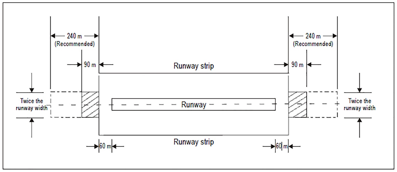
Figure GM-C-1. Runway end safety area for a runway where the code number is 3 or 4
[Issue: ADR-DSN/3]
[Issue: ADR-DSN/6]
CS ADR-DSN.C.215 Dimensions of runway end safety areas
ED Decision 2016/027/R
(a)Length of runway end safety area
(1)A runway end safety area should extend from the end of a runway strip to a distance of at least 90 m and, as far as practicable, extend to a distance of:
(i)240 m where the code number is 3 or 4 and
(ii)120 m where the code number is 1 or 2 and the runway is an instrument one; and
(2)A runway end safety area should extend from the end of a runway strip, as far as practicable, to a distance of 30 m where the code number is 1 or 2 and the runway is a non-instrument one.
(b)Notwithstanding the provisions in (a) above, the length of the runway end safety area may be reduced where an arresting system is installed, based on the design specifications of the system.
(c)Width of runway end safety area
The width of a runway end safety area should be at least twice that of the associated runway and, wherever practicable, be equal to that of the graded portion of the associated runway strip.
[Issue: ADR-DSN/3]
GM1 ADR-DSN.C.215 Dimensions of runway end safety areas
ED Decision 2014/013/R
It is accepted that many aerodromes were constructed before requirements for RESAs were introduced. For applicable runways where the RESA does not extend to the recommended distance, as part of their Safety Management System, aerodromes should assess the risk and implement appropriate and suitable mitigation measures as necessary.
CS ADR-DSN.C.220 Objects on runway end safety areas
ED Decision 2014/013/R
No fixed object, other than equipment and installations required for air navigation or for aeroplane safety purposes and satisfying the relevant frangibility requirement CS ADR-DSN.T.910, should be permitted on a runway end safety area. The detailed requirements for siting objects on a RESA are in CS ADR-DSN.T.915.
GM1 ADR-DSN.C.220 Objects on runway end safety areas
ED Decision 2014/013/R
Information regarding siting of equipment and installations on operational areas, including RESA, is detailed in CS ADR-DSN.T.915.
CS ADR-DSN.C.225 Clearing and grading of runway end safety areas
ED Decision 2014/013/R
A runway end safety area should provide a cleared and graded area for aeroplanes which the runway is intended to serve in the event of an aeroplane undershooting or overrunning the runway.
GM1 ADR-DSN.C.225 Clearing and grading of runway end safety areas
ED Decision 2016/027/R
(a)The surface of the runway end safety area should be prepared but does not need to be prepared to the same quality as the runway strip.
(b)Guidance on clearing and grading of runway end safety areas is given in ICAO Doc 9157, Aerodrome Design Manual, Part 1, Runways.
[Issue: ADR-DSN/3]
CS ADR-DSN.C.230 Slopes on runway end safety areas
ED Decision 2014/013/R
(a)Longitudinal slopes
(1)The slopes of a runway end safety area should be such that no part of the runway end safety area penetrates the approach or take-off climb surface.
(2)The longitudinal slopes of a runway end safety area should not exceed a downward slope of 5 %. Longitudinal slope changes should be as gradual as practicable, and abrupt changes or sudden reversals of slopes should be avoided.
(b)Transverse slopes
The transverse slopes of a runway end safety area should not exceed an upward or downward slope of 5 %. Transitions between differing slopes should be as gradual as practicable.
GM1 ADR-DSN.C.230 Slopes on runway end safety areas
ED Decision 2014/013/R
Where clearway is provided, the slope on the RESA should be amended accordingly.
CS ADR-DSN.C.235 Strength of runway end safety areas
ED Decision 2016/027/R
A runway end safety area should have a bearing strength sufficient to serve its primary purpose.
[Issue: ADR-DSN/3]
GM1 ADR-DSN.C.235 Strength of runway end safety areas
ED Decision 2016/027/R
(a)A runway end safety area should be so prepared or constructed as to reduce the risk of damage to an aeroplane undershooting or overrunning the runway, enhance aeroplane deceleration, and facilitate the movement of rescue and firefighting vehicles.
(b)Guidance on the strength of a runway end safety area is given in the GM1 ADR-DSN.B.190 Strength of runway strips and in ICAO Doc 9157, Aerodrome Design Manual, Part 1, Runways.
[Issue: ADR-DSN/3]
CS ADR-DSN.C.236 Engineered Materials Arresting System (EMAS)
ED Decision 2022/006/R
(a)An EMAS, provided in accordance with paragraph (b) of CS ADR-DSN.C.215, is a type of arresting system consisting of high energy absorbing materials of specific strength, which will reliably and predictably crush under the weight of an aircraft.
(b)Location: An EMAS should be located beyond the end of the runway or stopway, if provided, at enough setback distance to avoid damage due to jet blast.
(c)General: An EMAS should:
(1)be supported by a design method that can predict the performance of the system that is validated through laboratory or field tests;
(2)decelerate an aircraft overrunning the runway by exerting predictable forces on the landing gear without causing major structural damage to the aircraft and avoiding injuries to its occupants;
(3)be a passive system that requires no external means to initiate/trigger its operation to arrest an aircraft;
(4)be constructed not to be damaged by jet blast or projected debris during normal aircraft operations;
(5)use materials which do not generate nor worsen fire hazards to an incoming aircraft. The materials should be non-sparking, non-flammable, not promote combustion, and not emit toxic or malodorous fumes in a fire environment after installation;
(6)be compatible with the installation of approach lighting systems, the radio altimeter operating area and with the meteorological conditions and aerodrome environment;
(7)together with its surroundings, allow ice and snow removal and prevent water accumulation;
(8)have enough mechanical property to avoid damage resulting from personnel walking on it for routine maintenance;
(9)enable the access, movement, and egress of the RFFS vehicles without impeding their activities during an emergency;
(10)be designed for repair to a usable condition (conforming to the original specifications) after an overrun or other type of physical damage, and have an established maintenance programme;
(11)not increase the potential for damage and not cause control capabilities to an aircraft in case of an undershoot more than the risk associated with an undershoot in a RESA;
(12)be frangible and mounted as low as possible with ramps that are provided to avoid vertical surface;
(13)not impede crew and passenger evacuation nor hinder disabled aircraft removal procedures;
(14)not cause visual or electromagnetic interference with any air navigation aids nor have reflecting surfaces that could cause dazzling;
(15)not increase wildlife hazard;
(16)not be considered to meet the definition of a stopway as provided in CS ADR-DSN.A.002.
(d)Dimensions:
(1)The functional length of an EMAS should be designed based on the operating conditions of the associated runway with its centre line coincidental with the extended centre line of the runway.
(2)The functional width of an EMAS should not be less than the runway width.
(e)Arresting performance:
(1)An EMAS should be designed to decelerate the design aircraft at an exit speed of 70 knots at both maximum take-off weight (MTOW) and 80 % maximum landing weight (MLW) without imposing loads that exceed the aircraft’s design limits, causing major structural damage to the aircraft or imposing excessive forces on its occupants.
(2)When there is insufficient space available for the design on an EMAS in accordance with paragraph (c)(4) above, an EMAS should be designed to achieve the maximum arresting performance of the critical aeroplane.
(3)The design method for EMAS should factor in no reverse thrust of the aeroplane, using a 0.25 braking friction coefficient for the runway and length of pavement prior to the arrestor bed (setback).
(4)The design method for the EMAS assumes no braking friction coefficient (0.00) within the EMAS arrestor bed itself, unless the minimum actual braking friction coefficient that can be achieved as an aeroplane passes through the EMAS arrestor bed material can be demonstrated.
(f)Access:
(1)Slopes or steps should be provided to allow the entrance of the RFFS vehicles from the front and sides and to facilitate crew and passenger evacuation.
(2)On both sides of an EMAS, the requirements for RESA according CS ADR-DSN.C.210 to CS ADR-DSN.C.235 should be applied.
(3)Service roads should be set up for maintenance and emergency access. The width of the service roads should allow access and egress of RFFS vehicles. Service roads should be graded to avoid water accumulation. The strength of the service roads pavement should be capable of supporting the passage of fully loaded RFFS vehicles.
(g)Marking:
(1)An EMAS should be provided with yellow chevrons in accordance with
CS ADR-DSN.R.865.
[Issue: ADR-DSN/6]
GM1 ADR-DSN.C.236 Engineered Materials Arresting System (EMAS)
ED Decision 2022/006/R
(a)Engineered materials:
(1)The materials are tailored to specific mechanical properties and are referred to as engineered materials.
(2)The engineered materials have to meet a force-deformation profile within limits which have been shown to assure uniform characteristics, and therefore, predictable response to an aircraft entering the EMAS.
(3)The engineered materials will crush under the landing gears of the aeroplane when it engages the EMAS. The crushing is an irreversible or partly irreversible process and the arresting performance of the system is proportional to the amount of energy that is dissipated.
(b)The compatibility of the EMAS with the specific meteorological and aerodrome conditions is ensured by using materials which:
(1)are water-resistant to the extent that the presence of water does not affect system performance;
(2)do not attract or are physically vulnerable to:
(i)vermin,
(ii)birds,
(iii)wildlife, or
(iv)other creatures
to the greatest extent possible;
(3)do not support unintended plant growth with proper application of herbicides;
(4)exhibit constant strength and density characteristics during all climatic conditions within a temperature range that is appropriate for the local conditions;
(5)are resistant to deterioration as a result of:
(i)salt;
(ii)aircraft and runway de-icing and anti-icing fluids and solids;
(iii)aircraft fuels, hydraulic fluids, and lubricating oils;
(iv)ultraviolet;
(v)water;
(vi)freezing/thawing;
(vii)blowing sand and snow;
(viii)hail;
(viii)paint;
(ix)herbicides.
(c)Undershoot:
(1)An EMAS is not intended to reduce the risk of damage to an aeroplane undershooting the runway. However, the presence of an EMAS cannot increase the potential for damage in case of undershoot more than the risk that is associated with an undershoot in a RESA.
(2)Compliance with CS ADR-DSN.C.236 (c)(11) could be justified through experience of real cases of undershoot in an EMAS, flight simulator tests, other type of studies, or a combination of the three.
(d)An EMAS is a passive system which does not require any specific action or procedures by the flight crew. However, a basic knowledge of the systems by the crew is considered advantageous to prevent undesired evasive manoeuvres that could cause the aircraft to avoid entering the bed or system. The EMAS is designed to be entered preferably straight ahead with the unrestricted use of wheel brakes and/or thrust reversers. Additionally, the availability of an EMAS cannot be used for flight planning purposes, i.e., it cannot be included in the declared distances.
(e)Mechanical property:
(1)An EMAS is not intended to support vehicular traffic for maintenance or normal operating purposes.
(2)The EMAS needs to be capable of supporting personnel walking on it for the purposes of its own maintenance and co-located air navigation aids without causing any damage to its surface.
(3)Precaution needs to be taken during snow and ice removal to prevent damage to the EMAS bed.
(4)Light equipment for snow removal may be used in accordance with the manufacturer´s specification to avoid any damage to the surface.
(f)Setback distance:
(1)The setback distance is defined as the distance between the runway end or stopway, if provided, and the beginning of the EMAS.
(2)The setback distance will vary depending on the available area and the EMAS design.
(3)The calculation of the setback distance balances the risk objectives of:
(i)providing enough area for arresting purposes;
(ii)providing enough separation to protect the bed from jet blast;
(iii)providing separation from the threshold to reduce the probability of undershoot in the EMAS; and
(iv)decreasing the probability of aircraft overruns passing by one side of the EMAS due to lateral dispersion.
The safety assessment determines the relevance of each risk objective, taking into account the operating particularities of the associated runway, including usage of the runway, types of approach, weather conditions, fleet, incidents and accidents, and any other particularity related with runway safety.
(4)To reduce the probability of an aircraft undershooting in an EMAS, it is recommended to provide a minimum setback distance of at least 60 m from the threshold or runway end. However, this separation may be reduced if a safety assessment determines that it is the best alternative for both overrun and undershoot protection.
(g)An EMAS normally includes steps and/or slopes at its end and both sides, but they are not considered functional for arresting purposes. Where possible, the functional width of the EMAS is to be maintained the same throughout the whole length of the system.
(h)Exit speed is defined as the speed of the nose gear of the aeroplane as it passes the runway end or stopway, if provided.
(i)The critical aircraft is defined as the aircraft that regularly uses the associated runway that imposes the greatest demand upon the EMAS.
(j)Design aircraft list refers to the combination of aircraft types which are/will be operating regularly on the runway.
The critical aircraft is usually, but not always, the heaviest/largest aircraft that regularly uses the runway. The performance of an EMAS is dependent not only on aeroplane weight, but also on the landing gear configuration, tyre pressure, and centre of gravity. In general, the operational maximum take-off weight (operational MTOW) is used for the critical aircraft. However, there may be instances where less than the MTOW will require a longer EMAS. All parameters are to be considered in optimising the EMAS design. However, to the extent practicable, the EMAS design may consider both the aeroplane that imposes the greatest demand upon the EMAS and the range of aircraft expected to operate regularly on the runway. In some instances, a composite of design aircraft may be preferable to optimising the EMAS for a specific runway than a single critical aircraft. Other factors that are unique to a particular aerodrome, such as available RESA and air cargo operations, should also be considered in the final design.
(k)Testing:
Testing is to be based either on passage of an actual aircraft, or a single wheel bearing an equivalent load through a test bed. The design will need to consider multiple aircraft parameters, including but not limited to allowable aircraft gear loads, gear configuration, tyre contact pressure, weight, centre of gravity, and speed.
[Issue: ADR-DSN/6]
CHAPTER D — TAXIWAYS
CS ADR-DSN.D.240 Taxiways general
ED Decision 2017/021/R
Unless otherwise indicated, the requirements in Chapter D - Taxiways are applicable to all types of taxiways.
(a)The design of a taxiway should be such that, when the cockpit of the aeroplane for which the taxiway is intended, remains over the taxiway centre line markings, the clearance distance between the outer main wheel of the aeroplane and the edge of the taxiway should be not less than that given by the following tabulation:
Clearance | Outer Main Gear Wheel Span (OMGWS) | |||
Up to but not including 4.5 m | 4.5 m up to but not including 6 m | 6 m up to but not including 9 m | 9 m up to but not including 15 m | |
1.50 m | 2.25 m | 3 ma,b or 4 mc | 4 m | |
a on straight portions. b on curved portions if the taxiway is intended to be used by aeroplanes with a wheel base of less than 18 m. c on curved portions if the taxiway is intended to be used by aeroplanes with a wheel base equal to or greater than 18 m. | ||||
Note:Wheel base means the distance from the nose gear to the geometric centre of the main gear. | ||||
[Issue: ADR-DSN/4]
GM1 ADR-DSN.D.240 Taxiways general
ED Decision 2022/006/R
(a)Taxiways should be provided to permit the safe and expeditious surface movement of aircraft. Sufficient entrance and exit taxiways for a runway should be provided to expedite the movement of aeroplanes to and from the runway and provision of rapid exit taxiways considered when traffic volumes are high.
(b)Design of runway and taxiway infrastructure that either prevents aircraft entering or crossing a runway or mitigates the risk of an aircraft runway incursion collision should be considered both in the development of any new infrastructure and as a retrospective enhancement to existing infrastructure especially in hot-spot areas (areas where risk appraisal or incident data demonstrates a higher risk). This guidance may be considered as part of a runway incursion prevention programme and to help ensure that runway incursion aspects are addressed in any new design proposal.
(c)The initial approach should be to reduce the number of available entrances to the runway, so that the potential for entry to the runway at an unintended location is minimised. Taxiway entry, crossing and runway exit taxiways should be clearly identified and promulgated, using taxiing guidance signs, lighting and pavement markings.
(d)Many aerodromes have more than one runway, notably paired parallel runways (two runways on one side of the terminal apron), which create a difficult problem in that either on arrival or departure an aircraft is required to cross a runway. The potential for runway crossings should be eliminated or at least be as low as reasonably practicable. This may be achieved by constructing a ‘perimeter taxiway’ to enable aircraft to get to the departure runway or to the apron without either crossing a runway, or conflicting with an approaching or departing aircraft.
(e)A perimeter taxiway is ideally designed according to the following criteria:
(1)Sufficient space is required between the landing threshold and the taxiway centre line where it crosses under the approach path, to enable the critical aeroplane to pass under the approach without violating the approach surface.
(2)The extent of the jet blast impact of aircraft taking off is considered when determining the location of a perimeter taxiway.
(3)The requirement for RESA, as well as possible interference with the ILS or other navigation aids is also taken into account: the perimeter taxiway is located behind the localiser antenna, not between the localiser antenna and the runway, due to the potential for severe ILS disturbance, noting that this is harder to achieve as the distance between the localiser and the runway increases. Likewise, perimeter roads are provided where possible.
(4)Appropriate measures should be considered in order to assist pilots to distinguish between aircraft that are crossing the runway and those that are safely on a perimeter taxiway.
(f)Taxiways crossing runways should be provided at low energy locations, preferably at the runway ends. Where runway crossings cannot be eliminated, they should only be done on taxiways at right angles to a runway. This will afford the flight crew an unobstructed view of the runway, in both directions, to confirm that the runway and approach is clear of conflicting traffic before proceeding across.
(g)The runway/taxiway junction configuration should be simple, for example with single taxiway entrances; this is particularly relevant for taxiways crossing runways.
(h)The main design principles for entry and exit taxiways are:
(1)Taxiways should be perpendicular to the runway centre line if possible.
(2)The taxiway angle should be such that the crew of an aircraft at a taxiway holding position (if any) should be able to see an aircraft using or approaching the runway. Where the taxiway angle is such that this clear view, in both directions is not possible, consideration is given to provide a perpendicular portion of the taxiway immediately adjacent to the runway to allow for a full visual scan prior to entering (or crossing).
(3)Rapid exit taxiways are designed to be runway exits. Whilst it may be an operational practice at some airports to allow smaller aircraft the option of departing at a mid-point on the runway from one of these rapid exit taxiways, the geometry of the taxiway/runway intersection does not allow the crew to properly scan the runway in both directions to confirm that there is no conflicting traffic. This practice should thus be eliminated and from the design point of view, all signage and markings should deter any aircraft from using these rapid exit taxiways for any purpose other than what they are designed for (exiting the runway after landing). However, this may be mitigated by the addition of a fillet so that aircraft can manoeuvre to see down the approach. Note that aircraft on an angled taxiway may have a greater likelihood of causing ILS interference.
(4)A clear separation of pavement between a rapid exit taxiway and other non-rapid taxiways entering or crossing a runway should be provided. This design principle prevents two taxiways from overlapping with each other and creating an excessive paved area that would confuse pilots entering a runway.
(5)Limiting the options available to pilots on each entrance or exit helps to avoid confusion. Therefore, avoid dual or multiple taxiway entrances at one location, as Y-shaped connectors present opportunities for runway incursions and for aircraft vacating the runway to enter the wrong taxiway. Limiting the options available to pilots on each entrance or exit helps to avoid confusion.
(6)Runway/taxiway separations should be sufficient to permit space for effective RETs.
(7)Avoid designs which include crossing a runway to access a taxiway.
(8)Provide clear separation between high speed (RET) and taxi speed runway exits; if RETs are provided have a series in a row without other entrances.
(9)Where the aerodrome has more than one runway, ensure that runway ends are not too close together; if this is not possible ensure that they are clearly identified as separated. This may be achieved through visual aids, taxiway design and the taxiway naming convention.
(10)Surface colour should not create confusion:
(i)Have different colours for runway and taxiways.
(ii)Avoid a mix of concrete & asphalt.
(11)Wide taxiway entrances onto runways should be broken up with islands or barriers or painting taxiway edges with continuous edge markings to indicate unusable pavement. Avoid long holding position lines and excess paved areas which reduce the effectiveness of signs and markings. Use standard taxiway widths, suitable for a wide range of aeroplane, including the largest type expected to use the aerodrome.
(12)Avoid multi-taxiway intersections and reduce the number of taxiways at any intersection as far as possible.
(13)As far as practicable, it is preferable to redesign rather than reconfigure or repaint where possible – design errors out and reduce potential for human error.
(14)Consistent design of runway entrances – same visual aids at each, both taxiways and service road accesses.
(15)It is always preferable for safety reasons to have a taxiway parallel to the runway all along the runway, even if capacity constraints do not make it necessary.
(i)Aerodrome infrastructure can also be used to support design, whether by the systems installed or by their operating characteristics. Examples include:
(1)Stopbars and runway guard lights should be provided at all entrances, and preferably illuminated H24 and in all weather conditions. Runway incursions do not happen only under restricted visibilities. In fact, more incursions happen when the weather is good.
(2)Avoid confusion between CAT I and CAT III holding positions. This may be achieved in some circumstances by combining both holding positions.
(j)Multi-taxiway entrances to a runway should be parallel to each other and should be distinctly separated by an unpaved area. This design principle allows each runway holding location an earthen area for the proper placement of accompanying sign, marking, and lighting visual cues at each runway holding position. Moreover, the design principle eliminates the construction of unusable pavement and as well as the painting of taxiway edge markings to indicate such unusable pavement. In general, excess paved areas at runway holding positions reduce the effectiveness of sign, marking, and lighting visual cues.
(k)CS ADR-DSN.N.785 provides the certification specifications for a standardised scheme for the nomenclature of taxiways to improve situational awareness and as a part of an effective runway incursion prevention measure.
(l)Additional guidance on layout and standardised nomenclature of taxiways is given in ICAO Doc 9157, Aerodrome Design Manual, Part 2, Taxiways, Aprons and Holding Bays.
[Issue: ADR-DSN/3]
[Issue: ADR-DSN/4]
[Issue: ADR-DSN/6]
CS ADR-DSN.D.245 Width of taxiways
ED Decision 2017/021/R
A straight portion of a taxiway should have a width of not less than that given by the following tabulation:
Outer Main Gear Wheel Span (OMGWS) | ||||
Up to but not including 4.5 m | 4.5 m up to but not including 6 m | 6 m up to but not including 9 m | 9 m up to but not including 15 m | |
Taxiway width | 7.5 m | 10.5 m | 15 m | 23 m |
[Issue: ADR-DSN/4]
GM1 ADR-DSN.D.245 Width of taxiways
ED Decision 2017/021/R
(a)The width of the taxiway should be measured at the edge of the paved surface, or where the taxiway edge is marked, at the outside edge of the taxiway edge marking.
(b)Additional guidance on width of taxiways is given in ICAO Doc 9157, Aerodrome Design Manual, Part 2, Taxiways, Aprons and Holding Bays.
[Issue: ADR-DSN/4]
CS ADR-DSN.D.250 Taxiways curves
ED Decision 2014/013/R
(a)Changes in direction of taxiways should be as few and small as possible. The radii of the curves should be compatible with the manoeuvring capability and normal taxiing speeds of the aeroplanes for which the taxiway is intended.
(b)The design of the curve should be such that when the cockpit of the aeroplane for which the taxiway is intended remains over the taxiway centre line markings, the clearance distance between the outer main wheels of the aeroplane and the edge of the taxiway should be not less than those specified in CS ADR-DSN.D.240.
GM1 ADR-DSN.D.250 Taxiways curves
ED Decision 2016/027/R
(a)The location of taxiway centre line markings and lights is specified in CS ADR-DSN.L.555 and CS ADR-DSN.M.710.
(b)Compound curves may reduce or eliminate the need for extra taxiway width.
(c)An example of widening taxiways to achieve the wheel clearance specified is illustrated in Figure GM-D-1. Guidance on the values of suitable dimensions is given in ICAO Doc 9157, Aerodrome Design Manual, Part 2, Taxiways, Aprons and Holding Bays.
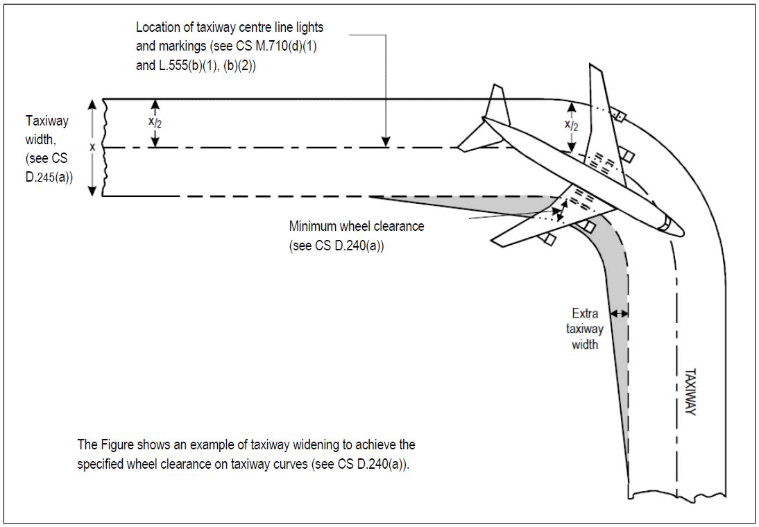
Figure GM-D-1. Taxiway curve
[Issue: ADR-DSN/3]
CS ADR-DSN.D.255 Junction and intersection of taxiways
ED Decision 2014/013/R
(a)To facilitate the movement of aeroplanes, fillets should be provided at junctions and intersections of taxiways with runways, aprons, and other taxiways.
(b)The design of the fillets should ensure that the minimum wheel clearances specified in
CS ADR-DSN.D.240 are maintained when aeroplanes are manoeuvring through the junctions or intersections.
GM1 ADR-DSN.D.255 Junction and intersection of taxiways
ED Decision 2016/027/R
Consideration should be given to the aeroplane datum length when designing fillets. Guidance on the design of fillets and the definition of the term aeroplane datum length are given in ICAO Doc 9157, Aerodrome Design Manual, Part 2, Taxiways, Aprons and Holding Bays.
[Issue: ADR-DSN/3]
CS ADR-DSN.D.260 Taxiway minimum separation distance
ED Decision 2017/021/R
(a)The safety objective of minimum taxi separation distances is to allow safe use of taxiways and aircraft stand taxilanes to prevent possible collision with other aeroplanes operating on adjacent runways or taxiways, or collision with adjacent objects.
(b)The separation distance between the centre line of a taxiway and the centre line of a runway, the centre line of a parallel taxiway or an object should not be less than the appropriate dimension specified in Table D-1.
Distance between taxiway centre line and runway centre line (metres) | Taxiway centre line to taxiway centre line (metres) | Taxiway, other than aircraft stand taxilane, centre line to object (metres) | Aircraft stand taxilane centre line to aircraft stand taxilane centre line (metres) | Aircraft stand taxilane centre line to object (metres) | |||||||||
Instrument runways Code number | Non-instrument runways Code number | ||||||||||||
Code letter | 1 | 2 | 3 | 4 | 1 | 2 | 3 | 4 | |||||
(1) | (2) | (3) | (4) | (5) | (6) | (7) | (8) | (9) | (10) | (11) | (12) | (13) | |
A | 77.5 | 77.5 | — | — | 37.5 | 47.5 | — | — | 23 | 15.5 | 19.5 | 12 | |
B | 82 | 82 | 152 | — | 42 | 52 | 87 | — | 32 | 20 | 28.5 | 16.5 | |
C | 88 | 88 | 158 | 158 | 48 | 58 | 93 | 93 | 44 | 26 | 40.5 | 22.5 | |
D | — | — | 166 | 166 | — | — | 101 | 101 | 63 | 37 | 59.5 | 33.5 | |
E | — | — | 172.5 | 172.5 | — | — | 107.5 | 107.5 | 76 | 43.5 | 72.5 | 40 | |
F | — | — | 180 | 180 | — | — | 115 | 115 | 91 | 51 | 87.5 | 47.5 | |
Note 1: The separation distances shown in columns (2) to (9) represent ordinary combinations of runways and taxiways. Note 2: The distances in columns (2) to (9) do not guarantee sufficient clearance behind a holding aeroplane to permit the passing of another aeroplane on a parallel taxiway. | |||||||||||||
Table D-1. Taxiway minimum separation distances
[Issue: ADR-DSN/2]
[Issue: ADR-DSN/4]
GM1 ADR-DSN.D.260 Taxiway minimum separation distance
ED Decision 2017/021/R
(a)Guidance on factors which may be considered in the safety assessment is given in ICAO Doc 9157, Aerodrome Design Manual, Part 2, Taxiways, Aprons and Holding Bays.
(b)ILS and MLS installations may also influence the location of taxiways due to interferences to ILS and MLS signals by a taxiing or stopped aircraft. Information on critical and sensitive areas surrounding ILS and MLS installations is contained in ICAO, Annex 10, Volume I, Attachments C and G (respectively).
(c)The separation distances, as prescribed in Table D-1, column (10), do not necessarily provide the capability of making a normal turn from one taxiway to another parallel taxiway. Guidance for this condition is given in ICAO Doc 9157, Aerodrome Design Manual, Part 2, Taxiways, Aprons and Holding Bays.
(d)The separation distance between the centre line of an aircraft stand taxilane and an object, as prescribed in Table D-1, column (13), may need to be increased when jet exhaust wake velocity may cause hazardous conditions for ground servicing.
(e)It may be permissible to operate with lower separation distances at an existing aerodrome if a safety assessment indicates that such lower separation distances would not adversely affect the safety or significantly affect the regularity of operations of aeroplanes.
(f)The separation distances, as prescribed in Table D-1, may have to be increased on taxiway curves to accommodate the wing sweep of the critical aeroplane or on dual parallel taxiways when, as for example, used as bypass taxiways.
(g)The requirements for apron taxiways regarding strip width, separation distances, etc., are the same as for any other type of taxiway.
[Issue: ADR-DSN/2]
[Issue: ADR-DSN/3]
[Issue: ADR-DSN/4]
CS ADR-DSN.D.265 Longitudinal slopes on taxiways
ED Decision 2014/013/R
(a)The safety objective of limiting the longitudinal taxiway slope is to enable stabilised safe use of taxiway by an aircraft.
(b)The longitudinal slope of a taxiway should not exceed:
(1)1.5 % where the code letter is C, D, E, or F; and
(2)3 % where the code letter is A or B.
GM1 ADR-DSN.D.265 Longitudinal slopes on taxiways
ED Decision 2014/013/R
intentionally left blank
CS ADR-DSN.D.270 Longitudinal slope changes on taxiways
ED Decision 2014/013/R
(a)The safety objective of limiting the longitudinal taxiway slope changes is to avoid damage of aircraft and to enable safe use of taxiway by an aircraft.
(b)Where slope changes on a taxiway cannot be avoided, the transition from one slope to another slope should be accomplished by a curved surface with a rate of change not exceeding:
(1)1 % per 30 m (minimum radius of curvature of 3 000 m) where the code letter is C, D, E, or F; and
(2)1 % per 25 m (minimum radius of curvature of 2 500 m) where the code letter is A or B.
(c)Where slope changes in (b)(1) and (2) are not achieved and slopes on a taxiway cannot be avoided, the transition from one slope to another slope should be accomplished by a curved surface which should allow the safe operation of all aircraft in all weather conditions.
GM1 ADR-DSN.D.270 Longitudinal slope changes on taxiways
ED Decision 2014/013/R
intentionally left blank
CS ADR-DSN.D.275 Sight distance of taxiways
ED Decision 2014/013/R
(a)The safety objective of minimum taxiway sight distance values is to achieve the necessary visibility to enable safe use of taxiway by an aircraft.
(b)Where a change in slope on a taxiway cannot be avoided, the change should be such that, from any point:
(1)3 m above the taxiway, it should be possible to see the whole surface of the taxiway for a distance of at least 300 m from that point where the code letter is C, D, E, or F;
(2)2 m above the taxiway, it should be possible to see the whole surface of the taxiway for a distance of at least 200 m from that point where the code letter is B; and
(3)1.5 m above the taxiway, it should be possible to see the whole surface of the taxiway for a distance of at least 150 m from that point where the code letter is A.
GM1 ADR-DSN.D.275 Sight distance of taxiways
ED Decision 2014/013/R
intentionally left blank
CS ADR-DSN.D.280 Transverse slopes on taxiways
ED Decision 2014/013/R
(a)The safety objective of taxiway transverse slopes is to promote the most rapid drainage of water from the taxiway.
(b)The transverse slopes of a taxiway should be sufficient to prevent the accumulation of water on the surface of the taxiway but should not exceed:
(1)1.5 % where the code letter is C, D, E, or F; and
(2)2 % where the code letter is A or B.
GM1 ADR-DSN.D.280 Transverse slopes on taxiways
ED Decision 2014/013/R
The slopes on a taxiway are intended to prevent the accumulation of water (or possible fluid contaminant) on the surface and to facilitate rapid drainage of surface water (or possible fluid contaminant). Slopes should be so designed as to minimise impact on aircraft and so not to hamper the operation of aircraft.
CS ADR-DSN.D.285 Strength of taxiways
ED Decision 2014/013/R
The strength of a taxiway should be suitable for the aircraft that the taxiway is intended to serve.
GM1 ADR-DSN.D.285 Strength of taxiways
ED Decision 2022/006/R
(a)Due consideration is to be given to the fact that a taxiway is subjected to a greater density of traffic and as a result of slow moving and stationary aeroplanes, to higher stresses than the runway it serves.
(b)The method for reporting the bearing strength of the pavement is available in Part-ADR.OPS of Regulation (EU) No 139/2014.
(c)Additional information on the bearing strength, the design, and evaluation of pavements is given in ICAO Doc 9157, Aerodrome Design Manual, Part 3, Pavements.
[Issue: ADR-DSN/3]
[Issue: ADR-DSN/6]
CS ADR-DSN.D.290 Surface of taxiways
ED Decision 2016/027/R
(a)The surface of a taxiway should not have irregularities that cause damage to aeroplane structures.
(b)The surface of a paved taxiway should be so constructed or resurfaced as to provide suitable surface friction characteristics.
[Issue: ADR-DSN/3]
GM1 ADR-DSN.D.290 Surface of taxiways
ED Decision 2016/027/R
Suitable surface friction characteristics are those surface properties required on taxiways that assure safe operation of aeroplanes.
[Issue: ADR-DSN/3]
CS ADR-DSN.D.295 Rapid exit taxiways
ED Decision 2014/013/R
(a)The safety objective of rapid exit taxiway is to facilitate safe rapid exit of aeroplanes from a runway.
(b)A rapid exit taxiway should be designed with a radius of turn-off curve of at least:
(1)550 m where the code number is 3 or 4; and
(2)275 m where the code number is 1 or 2;
to enable under wet conditions exit speeds of:
(i)93 km/h where the code number is 3 or 4; and
(ii)65 km/h where the code number is 1 or 2.
(c)The radius of the fillet on the inside of the curve at a rapid exit taxiway should be sufficient to provide a widened taxiway throat in order to facilitate early recognition of the entrance and turn-off onto the taxiway.
(d)A rapid exit taxiway should include a straight distance after the turn-off curve sufficient for an exiting aircraft to come to a full stop clear of any intersecting taxiway (Figure D-1).
(e)The intersection angle of a rapid exit taxiway with the runway should not be greater than 45°, nor less than 25° and preferably should be 30°.
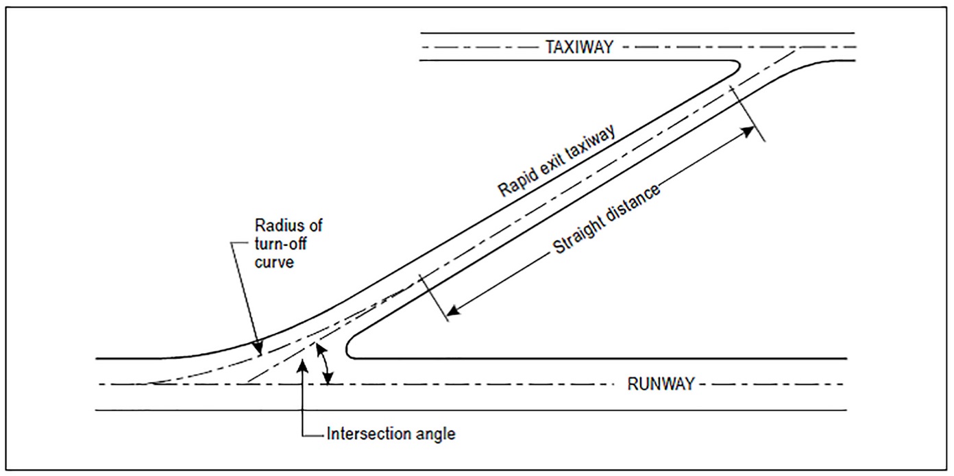
Figure D-1. Rapid exit taxiway
GM1 ADR-DSN.D.295 Rapid exit taxiways
ED Decision 2021/004/R
(a)The following guidance applies particularly to rapid exit taxiways (see Figure D-1). The general requirements for taxiways, as prescribed in the relevant certification specifications, are also applicable to rapid exit taxiways. Guidance on the provision, location and design of rapid exit taxiways is included in ICAO Doc 9157, Aerodrome Design Manual, Part 2, Taxiways, Aprons and Holding Bays.
(b)The locations of rapid exit taxiways along a runway are based on several criteria described in ICAO Doc 9157, Aerodrome Design Manual, Part 2, Taxiways, Aprons and Holding Bays, in addition to different speed criteria.
[Issue: ADR-DSN/3]
[Issue: ADR-DSN/5]
CS ADR-DSN.D.300 Taxiways on bridges
ED Decision 2014/013/R
(a)The width of that portion of a taxiway bridge capable of supporting aeroplanes, as measured perpendicularly to the taxiway centre line, should not be less than the width of the graded area of the strip provided for that taxiway unless a proven method of lateral restraint is provided which should not be hazardous for aeroplanes for which the taxiway is intended.
(b)Access should be provided to allow rescue and firefighting vehicles to intervene in both directions within the specified response time to the largest aeroplane for which the taxiway bridge is intended.
(c)A bridge should be constructed on a straight section of the taxiway with a straight section on both ends of the bridge to facilitate the alignment of aeroplanes approaching the bridge.
GM1 ADR-DSN.D.300 Taxiways on bridges
ED Decision 2014/013/R
If aeroplane engines overhang the bridge structure, protection of adjacent areas below the bridge from engine blast may be required.
CS ADR-DSN.D.305 Taxiway shoulders
ED Decision 2017/021/R
(a)Straight portions of a taxiway where the code letter is C, D, E, or F should be provided with shoulders which extend symmetrically on each side of the taxiway so that the overall width of the taxiway and its shoulders on straight portions is not less than:
(1)44 m where the code letter is F;
(2)38 m where the code letter is E;
(3)34 m where the code letter is D; and
(4)25 m where the code letter is C.
(b)On taxiway curves and on junctions or intersections where increased pavement is provided, the shoulder width should be not less than that on the adjacent straight portions of the taxiway.
(c)When a taxiway is intended to be used by turbine-engined aeroplanes, the surface of the taxiway shoulder should be prepared so as to resist erosion and the ingestion of the surface material by aeroplane engines.
[Issue: ADR-DSN/4]
GM1 ADR-DSN.D.305 Taxiway shoulders
ED Decision 2016/027/R
Guidance on characteristics of taxiway shoulders and on shoulder treatment is given in ICAO Doc 9157, Aerodrome Design Manual, Part 2, Taxiways, Aprons and Holding Bays.
[Issue: ADR-DSN/3]
CS ADR-DSN.D.310 Taxiway Strip
ED Decision 2014/013/R
A taxiway, other than an aircraft stand taxilane, should be included in a strip.
GM1 ADR-DSN.D.310 Taxiway Strip
ED Decision 2016/027/R
A taxiway strip should be so prepared or constructed as to minimise hazards arising from differences in load bearing capacity to aeroplanes which the taxiway is intended to serve in the event of an aeroplane accidentally running off the taxiway.
Guidance on characteristics of taxiway strips is given in ICAO Doc 9157, Aerodrome Design Manual, Part 2, Taxiways, Aprons and Holding Bays.
[Issue: ADR-DSN/3]
CS ADR-DSN.D.315 Width of taxiway strips
ED Decision 2016/027/R
(a)The safety objective of the width of taxiway strips is to allow safe use of taxiways in relation to adjacent objects.
(b)A taxiway strip should extend symmetrically on each side of the centre line of the taxiway throughout the length of the taxiway to at least the distance from the centre line given in Table D-1, column (11).
[Issue: ADR-DSN/3]
GM1 ADR-DSN.D.315 Width of taxiway strips
ED Decision 2014/013/R
intentionally left blank
CS ADR-DSN.D.320 Objects on taxiway strips
ED Decision 2014/013/R
The taxiway strip should provide an area clear of objects which may endanger taxiing aeroplanes.
GM1 ADR-DSN.D.320 Objects on taxiway strips
ED Decision 2017/021/R
(a)Consideration should be given to the location and design of drains on a taxiway strip to prevent damage to an aeroplane accidentally running off a taxiway. Suitably designed drain covers may be required.
(b)The detailed requirements for siting objects on taxiway strips are in CS ADR-DSN.T.915.
(c)Where open-air or covered storm water conveyances are installed, consideration should be given in order to ensure that their structure does not extend above the surrounding ground so as not to be considered an obstacle.
(d)Particular attention needs to be given to the design and maintenance of an open-air storm water conveyance in order to prevent wildlife attraction, in particular birds. The open-air storm water conveyance may be covered by a net, if required. Further guidance is given in ICAO Doc 9137, Airport Services Manual, Part 3, Wildlife Control and Reduction.
(e)Guidance on the design of drain covers is given in ICAO Doc 9157, Aerodrome Design Manual, Part 2, Taxiways, Aprons and Holding Bays.
[Issue: ADR-DSN/4]
CS ADR-DSN.D.325 Grading of taxiway strips
ED Decision 2017/021/R
(a)The safety objective of the grading of a taxiway strip is to reduce the risk of damage to an aircraft accidentally running off the taxiway.
(b)The centre portion of a taxiway strip should provide a graded area to a distance from the centre line of the taxiway of not less than that given by the following tabulation:
(1)10.25 m where the OMGWS is up to but not including 4.5 m;
(2)11 m where the OMGWS is 4.5 m up to but not including 6 m;
(3)12.50 m where the OMGWS is 6 m up to but not including 9 m;
(4)18.50 m where the OMGWS is 9 m up to but not including 15 m, where the code letter is D;
(5)19 m where the OMGWS is 9 m up to but not including 15 m, where the code letter is E;
(6)22 m where the OMGWS is 9 m up to but not including 15 m, where the code letter is F.
[Issue: ADR-DSN/4]
GM1 ADR-DSN.D.325 Grading of taxiway strips
ED Decision 2017/021/R
Further guidance on the width of the graded portion of a taxiway is given in ICAO Doc 9157, Aerodrome Design Manual, Part 2, Taxiways, Aprons and Holding Bays.
[Issue: ADR-DSN/4]
CS ADR-DSN.D.330 Slopes on taxiway strips
ED Decision 2014/013/R
(a)The safety objective of limiting the longitudinal taxiway strip slopes and slope changes and of minimum sight distances values is to reduce the probability of damage to an aircraft accidentally running off the taxiway and to enable safe use of these areas by rescue and firefighting vehicles.
(b)The surface of the strip should be flush at the edge of the taxiway or shoulder if provided, and the graded portion should not have an upward transverse slope exceeding:
(1)2.5 % for strips where the code letter is C, D, E, or F; and
(2)3 % for strips of taxiways where the code letter is A or B;
the upward slope being measured with reference to the transverse slope of the adjacent taxiway surface and not the horizontal. The downward transverse slope should not exceed 5 % measured with reference to the horizontal.
(c)The transverse slopes on any portion of a taxiway strip beyond that to be graded should not exceed an upward or downward slope of 5 % as measured in the direction away from the taxiway.
GM1 ADR-DSN.D.330 Slopes on taxiway strips
ED Decision 2017/021/R
(a)Where required for proper drainage, an open-air storm water conveyance may be allowed in the non-graded portion of a taxiway strip and should be placed as far as practicable from the taxiway.
(b)The locations of open-air storm water conveyances within the non-graded portion of a taxiway strip should be so designed to permit unobstructed access for rescue and firefighting services (RFFS).
[Issue: ADR-DSN/4]
CS ADR-DSN.D.335 Holding bays, runway-holding positions, intermediate holding positions, and road-holding positions
ED Decision 2016/027/R
(a)Holding bay(s) or other bypasses of sufficient size and adequate construction should be provided where necessary, to make deviations in the departure sequence possible.
(b)A runway-holding position or positions should be established:
(1)on the taxiway, if the location or alignment of the taxiway is such that a taxiing aircraft or vehicle can infringe an obstacle limitation surface or ILS/MLS critical/sensitive area or interfere with the operation of radio navigation aids;
(2)on the taxiway, at the intersection of a taxiway and a runway; and
(3)at an intersection of a runway with another runway when the former runway is part of a standard taxi-route.
(c)An intermediate holding position should be established on a taxiway at any point other than a runway-holding position where it is desirable to define a specific holding limit.
(d)An emergency access road should be equipped with road-holding positions at all intersections with runways and taxiways.
(e)A road-holding position should be established at each intersection of a road with a runway.
[Issue: ADR-DSN/3]
GM1 ADR-DSN.D.335 Holding bays, runway-holding positions, intermediate holding positions, and road-holding positions
ED Decision 2016/027/R
(a)At low levels of aerodrome activity (less than approximately 50 000 annual operations), there is normally little need to make deviations in the departure sequence. However, for higher activity levels, aerodromes with single taxiways and no holding bays or other bypasses provide aerodrome control units with no opportunity to change the sequence of departures once the aircraft have left the apron. In particular, at aerodromes with large apron areas, it is often difficult to arrange for aircraft to leave the apron in such a way that they should arrive at the end of the runway in the sequence required by air traffic services units.
(b)The provision of an adequate number of holding bay spaces or other bypasses, based upon an analysis of the current and near-term hourly aircraft departure demand, should allow a large degree of flexibility in generating the departure sequence.
(c)The space required for a holding bay depends on the number of aircraft positions to be provided, the size of the aircraft to be accommodated, and the frequency of their utilisation. The dimensions should allow for sufficient space between aircraft to enable them to manoeuvre independently.
(d)Emergency access roads are not intended for use for the functions of aerodrome service roads. However, they should be provided by different access controls which should be clearly visible for all service ground traffic.
(e)Further guidance is given in ICAO Doc 9157, Aerodrome Design Manual, Part 2, Taxiways, Aprons and Holding Bays and ICAO Doc 4444, Procedures for Air Navigation Services — Air Traffic Management.
[Issue: ADR-DSN/3]
CS ADR-DSN.D.340 Location of holding bays, runway-holding positions, intermediate holding positions, and road-holding positions
ED Decision 2022/006/R
(a)The distance between a holding bay, runway-holding position established at a taxiway/runway intersection or road-holding position and the centre line of a runway should be in accordance with Table D-2 and such that a holding aircraft or vehicle should not interfere with the operation of radio navigation aids or penetrate the inner transitional surface.
(b)At elevations greater than 700 m the distance of 90 m specified in Table D-2 for a precision approach runway code number 4 should be increased as follows:
(1)up to an elevation of 2 000 m; 1 m for every 100 m in excess of 700 m;
(2)elevation in excess of 2 000 m and up to 4 000 m; 13 m plus 1.5 m for every 100 m in excess of 2 000 m; and
(3)elevation in excess of 4 000 m and up to 5 000 m; 43 m plus 2 m for every 100 m in excess of 4 000 m.
(c)The location of a runway-holding position established in accordance with CS ADR-DSN.D.335 should be such that a holding aircraft or vehicle will not infringe the obstacle-free zone, approach surface, take-off climb surface or ILS/MLS critical/sensitive area or interfere with the operation of radio navigation aids.
Type of runway | Code numberd | |||
1 | 2 | 3 | 4 | |
Non-instrument | 30 m | 40 m | 75 m | 75 m |
Non-precision approach | 40 m | 40 m | 75 m | 75 m |
Precision approach Category I | 60 mb | 60 mb | 90 ma,b | 90 ma,b,c |
Precision approach Categories II and III | — | — | 90 ma,b | 90 ma,b,c |
Take-off runway | 30 m | 40 m | 75 m | 75 m |
a.If a holding bay, runway-holding position, or road-holding position is at a lower elevation compared to the threshold, the distance may be decreased 5 m for every metre the bay or holding position is lower than the threshold, contingent upon not infringing the inner transitional surface. b.This distance may need to be increased to avoid interference with radio navigation aids, particularly the glide path and localiser facilities (see CS ADR-DSN.D.340). Note 1: The distance of 90 m for code number 3 or 4 is based on an aircraft with a tail height of 20 m, a distance from the nose to the highest part of the tail of 52.7 m and a nose height of 10 m holding at an angle of 45° or more with respect to the runway centre line, being clear of the obstacle-free zone and not accountable for the calculation of OCA/H. Note 2: The distance of 60 m for code number 2 is based on an aircraft with a tail height of 8 m, a distance from the nose to the highest part of the tail of 24.6 m and a nose height of 5.2 m holding at an angle of 45° or more with respect to the runway centre line, being clear of the obstacle-free zone. c.Where the code letter is F, this distance should be at least 100 m. Note: The distance of 100 m for code number 4 where the code letter is F is based on an aircraft with a tail height of 24 m, a distance from the nose to the highest part of the tail of 62.2 m and a nose height of 10 m holding at an angle of 45° or more with respect to the runway centre line, being clear of the obstacle-free zone. d.Elevation of taxiway should be taken into account for possible increase of the distances indicated in this table. | ||||
Table D-2. Minimum distance from the runway centre line to a holding bay, runway-holding position, or road-holding position
[Issue: ADR-DSN/3]
[Issue: ADR-DSN/6]
GM1 ADR-DSN.D.340 Location of holding bays, runway-holding positions, intermediate holding positions, and road-holding positions
ED Decision 2022/006/R
(a)Care should be taken so that propeller wash and jet blast from holding aircraft do not interfere with aircraft operations, cause damage to vehicles, or injure people.
(b)Generally, when used to allow flexible departure sequencing, the most advantageous location for a holding bay is adjacent to the taxiway serving the runway end. Other locations along the taxiway are satisfactory for aircraft performing pre-flight checks or engine run-ups, or as a holding point for aircraft awaiting departure clearance.
(c)An aircraft taxiing could endanger aircraft operations when the aircraft is too close to the runway during take-off and landings. It is so advised to check if the aircraft taking off or landing could be hinder. For this OLS and specially approach surfaces, take-off climb surfaces and OFZ are the first aspects to consider. An aircraft taxiing could also endanger aircraft operations when the aircraft location and orientation are so that the aircraft interfere with navigation aids. It is specific to instrument runways and especially important for precision approach runways. The non-penetration of critical/sensitive areas is the first check. The areas within which this degradable interference of course or path signals are possible need to be defined and recognised. For the purposes of developing protective zoning criteria for ILS, these areas are critical areas and sensitive areas. The ILS critical area is an area of defined dimensions about the localizer and glide path antennas where vehicles, including aircraft, are excluded during all ILS operations. The critical area is protected, since the presence of vehicles and/or aircraft inside the critical area boundaries would cause unacceptable disturbance to the ILS signal. The ILS sensitive area is an area extending beyond the critical area where the parking and/or movement of vehicles, including aircraft, is controlled to prevent the possibility of unacceptable interference to the ILS signal during ILS operations.
(d)For all runways, it should be verified that the distance between a holding bay, runway-holding position established at a taxiway/runway intersection or road-holding position and the centre line of a runway is so that a holding aircraft or vehicle should not infringe the approach surface and/or take-off climb surface.
(e)If the affected runway is used under precision approach procedures, it should be also verified that the distance between a holding bay, runway-holding position established at a taxiway/runway intersection or road-holding position and the centre line of a runway is so that a holding aircraft or vehicle should not infringe the obstacle-free zone and the critical/sensitive areas of precision approach navigation aids (e.g. ILS/MLS).
(f)If a holding bay, runway-holding position or road-holding position for a precision approach runway code number 4 is at a greater elevation compared to the threshold, the distance specified in Table D-2 could be further increased 5 m for every metre the bay or position is higher than the threshold.
(g)An aircraft taxiing could also endanger aircraft operation when the aircraft is too close to other taxiing aircraft. For this, separation distances or margins between taxiing aircraft or taxiways should be considered.
(h)In radiotelephony phraseologies, the expression ‘holding point’ is used to designate the runway-holding position.
(i)Further guidance is given in ICAO Doc 9157, Aerodrome Design Manual, Part 2, Taxiways, Aprons and Holding Bays.
[Issue: ADR-DSN/3]
[Issue: ADR-DSN/6]
CHAPTER E — APRONS
CS ADR-DSN.E.345 General
ED Decision 2014/013/R
Aprons should be provided to permit the safe loading and off-loading of passengers, cargo, or mail as well as the servicing of aircraft without interfering with the aerodrome traffic.
GM1 ADR-DSN.E.345 General
ED Decision 2014/013/R
intentionally left blank
CS ADR-DSN.E.350 Size of aprons
ED Decision 2014/013/R
intentionally left blank
GM1 ADR-DSN.E.350 Size of aprons
ED Decision 2016/027/R
(a)The total apron area should be adequate to permit safe and expeditious handling of aerodrome traffic at its maximum anticipated density.
(b)The amount of area required for a particular apron layout depends upon the following factors:
(1)the size and manoeuvrability characteristics of the aircraft using the apron;
(2)the volume of traffic using the apron;
(3)clearance requirements;
(4)type of ingress and egress to the aircraft stand;
(5)basic terminal layout or other aerodrome use;
(6)aircraft ground activity requirements; and
(7)taxiways and apron service roads.
(c)Passenger aircraft services that are carried out during the time the aircraft is parked in a stand position include: galley; toilet and potable water service; baggage handling; fuelling; provision of air conditioning, oxygen, electrical power supply and starting air; and aircraft towing. Most of these functions have a vehicle and/or equipment associated with them, or have some type of fixed installation established to conduct these services. Further guidance is given in ICAO Doc 9157, Aerodrome Design Manual, Part 2, Taxiways, Aprons and Holding Bays, paragraph 3.4.6.
(d)Consideration should be given to providing sufficient area on the starboard side of the aircraft to support the level of activity that take place in the turnaround operation. Further guidance is given in ICAO Doc 9157, Aerodrome Design Manual, Part 2, Taxiways, Aprons and Holding Bays, paragraph 3.4.6.
[Issue: ADR-DSN/3]