
Filters
GM1 ADR-DSN.T.900 Emergency access and service roads
ED Decision 2016/027/R
(a)Service roads at air side are installed to support all apron processes. Furthermore, service roads can be used as aerodrome perimeter service roads, providing access to navigation aids, as temporary roads for construction vehicles, etc.
(b)Some general considerations in the planning of roads are described as follows:
(1)Every effort should be made to plan service roads at air side so that they do not cross runways and taxiways.
(2)The planning of the aerodrome road layout should take into account the need to provide emergency access roads for use by rescue and firefighting vehicles to various areas on the aerodrome, and, in particular, to the approach areas. Service roads to navigation aids should be planned in such a manner as to present minimal interference to the function of the aids. If it is necessary for a service road to cross an approach area, the road should be located so that vehicles travelling on it are not obstacles to aircraft operations.
(3)The service roads at air side system should be designed to account for local security measures. Access points to the system should, thus, need to be restricted. Should ground vehicle movements affect surface movement of aircraft on runways and taxiways, it should be required that the ground vehicle movements be coordinated by the appropriate aerodrome control. Control is normally exercised by means of two-way radio communication although visual signals, such as signal lamps, are adequate when traffic at the aerodrome is light. Signs or signals may also be employed to aid control at intersections.
(4)At intersections with runways consideration should be given to providing runway guard lights or road-holding position lights as part of the aerodrome’s runway incursion prevention programme. Runway guard lights should conform to the specifications provided in CS ADR-DSN.M.745.
(5)Roads should be designed and constructed to prevent FOD transfer to the runway and taxiways.
(6)Roads within 90 m of a runway centre line generally should be surfaced to prevent surface erosion, and the transfer of debris to the runway and taxiways.
(7)To facilitate the control and maintenance of the fencing, a perimeter service road should be constructed inside the aerodrome fencing.
(8)Perimeter service road is also used by security patrols.
(9)Where a fence is provided, the need for convenient access to outside areas should be taken into account. These access points should be of a suitable size to accommodate the passage of the largest RFFS vehicle in the aerodrome’s fleet.
(10)When greater security is thought necessary, a cleared area should be provided on both sides of the fence or barrier to facilitate the work of patrols, and to make trespassing more difficult.
(11)Special measures should be required to prevent the access of an unauthorised person to runways or taxiways which overpass public roads.
(c)Emergency access roads should be considered on an aerodrome so as to facilitate achieving minimum response times for RFF vehicles.
(d)Emergency access roads should be provided on an aerodrome where terrain conditions permit their construction, so as to facilitate achieving minimum response times. Particular attention should be given to the provision of ready access to approach areas up to 1 000 m from the threshold, or at least within the aerodrome boundary.
(e)Emergency access roads are not intended for use for the functions of aerodrome service roads. Therefore, it is possible to provide different access control which should be clearly visible for all service ground traffic. Road-holding position markings, lights, or runway guard lights are not necessary if the access to an emergency access road is ensured for RFF only.
(f)Aerodrome service roads may serve as emergency access roads when they are suitably located and constructed.
(g)Emergency access roads should be capable of supporting the heaviest vehicles which should use them, and be usable in all weather conditions. Roads within 90 m of a runway centre line should be surfaced to prevent surface erosion and the transfer of debris to the runway. Sufficient vertical clearance should be provided from overhead obstructions for the largest vehicles.
(h)When the surface of the road is indistinguishable from the surrounding area, or in areas where snow may obscure the location of the roads, edge markers should be placed at intervals of about 10 m.
[Issue: ADR-DSN/3]
CS ADR-DSN.T.905 Fire stations
ED Decision 2014/013/R
(a)All rescue and firefighting vehicles should normally be housed in a fire station. Satellite fire stations should be provided whenever the response time cannot be achieved from a single fire station.
(b)The fire station should be located so that the access for rescue and firefighting vehicles into the runway area is direct and clear, requiring a minimum number of turns.
(c)The fire station, and any satellite fire stations, should be located outside taxiway and runway strips, and not infringe obstacle limitation surfaces.
GM1 ADR-DSN.T.905 Fire stations
ED Decision 2014/013/R
intentionally left blank
CS ADR-DSN.T.910 Equipment frangibility requirements
ED Decision 2014/013/R
Equipment and structures should be so designed to meet the appropriate frangibility characteristics, when required.
GM1 ADR-DSN.T.910 Equipment frangibility requirements
ED Decision 2016/027/R
(a)Equipment and supports required to be frangible should be designed and constructed so that they should break, distort, or yield in the event that they are accidentally impacted by an aircraft. The design materials selected should preclude any tendency for the components, including the electrical conductors, etc., to ‘wrap around’ the colliding aircraft or any part of it.
(b)Frangible structures should be designed to withstand the static and operational wind or jet blast loads with a suitable factor of safety but should break, distort, or yield readily when subjected to the sudden collision forces of a 3 000 kg aircraft airborne and travelling at 140 km/h (75 kt), or moving on the ground at 50 km/h (27 kt).
(c)Guidance on design for frangibility is contained in ICAO Doc 9157, Aerodrome Design Manual, Part 6, Frangibility.
[Issue: ADR-DSN/3]
CS ADR-DSN.T.915 Siting of equipment and installations on operational areas
ED Decision 2022/006/R
(a)Equipment and installations should be sited as far away from the runway and taxiway centre lines as practicable.
(b)Unless its function requires it to be there for air navigation or for aircraft safety purposes, no equipment or installation endangering an aircraft should be located:
(1)on a runway strip, a runway end safety area, a taxiway strip, or within the following distances:
Code Letter | Distance between taxiway, other than aircraft stand taxilane, centre line to object (metres) |
A | 15.5 |
B | 20 |
C | 26 |
D | 37 |
E | 43.5 |
F | 51 |
if it would endanger an aircraft, or
(2)on a clearway if it would endanger an aircraft in the air.
(c)Any equipment or installation required for air navigation or for aircraft safety purposes which should be located:
(1)on that portion of a runway strip within:
(i)75 m of the runway centre line where the code number is 3 or 4; or
(ii)45 m of the runway centre line where the code number is 1 or 2; or
(2)on a runway end safety area, a taxiway strip, or within the distances specified in Table D-1; or
(3)on a clearway and which would endanger an aircraft in the air;
should be frangible and mounted as low as possible.
(d)Unless its function requires it to be there for air navigation or for aircraft safety purposes, or if after a safety assessment, it is determined that it would not adversely affect the safety or significantly affect the regularity of operations of aeroplanes, no equipment or installation should be located within 240 m from the end of the strip and within:
(1)60 m of the extended centre line where the code number is 3 or 4; or
(2)45 m of the extended centre line where the code number is 1 or 2;
of a precision approach runway Category I, II or III.
(e)Any equipment or installation required for air navigation or for aircraft safety purposes, which should be located on or near a strip of a precision approach runway Category I, II, or III and which:
(1)is situated within 240 m from the end of the strip and within:
(i)60 m of the extended runway centre line where the code number is 3 or 4; or
(ii)45 m of the extended runway centre line where the code number is 1 or 2; or
(2)penetrates the inner approach surface, the inner transitional surface, or the balked landing surface;
should be frangible and mounted as low as possible.
(f)Any equipment or installation required for air navigation or for aircraft safety purposes that is an obstacle of operational significance in accordance with CS ADR-DSN.J.470(d),
CS ADR-DSN.J.475(e), CS ADR-DSN.J.480(g), or CS ADR-DSN.J.485(e) should be frangible and mounted as low as possible.
(g)Any equipment or installation required for air navigation or for aircraft safety purposes which should be located on the non-graded portion of a runway strip should be regarded as an obstacle and should be frangible and mounted as low as possible.
[Issue: ADR-DSN/2]
[Issue: ADR-DSN/3]
[Issue: ADR-DSN/6]
GM1 ADR-DSN.T.915 Siting of equipment and installations on operational areas
ED Decision 2022/006/R
(a)The design of light fixtures and their supporting structures, light units of visual approach slope indicators, signs and markers is specified in CS ADR-DSN.M.615, CS ADR-DSN.M.640,
CS ADR-DSN.N.775, and the certification specifications of Chapter P respectively.
(b)Guidance on siting of equipment and installations on operational areas is given in ICAO Doc 9157, Aerodrome Design Manuals, Part 2, Taxiways, Aprons and Holding Bays and Part 6, Frangibility.
(c)Guidance on the frangible design of visual and non-visual aids for navigation is given in the ICAO Doc 9157, Aerodrome Design Manual, Part 5, Electrical Systems.
(d)Requirements for obstacle limitation surfaces are specified in the certification specifications of Chapter J.
(e)The term ‘aircraft safety purposes’ refers to the installation of arresting systems.
[Issue: ADR-DSN/3]
[Issue: ADR-DSN/5]
[Issue: ADR-DSN/6]
CS ADR-DSN.T.920 Fencing
ED Decision 2014/013/R
(a)The safety objective of fencing is to prevent animals or unauthorised persons that could be a safety risk to aircraft operations, to enter the aerodrome.
(b)Fencing should be sited as far away from the runway and taxiway centre lines as practicable.
(c)Suitable means of protection such as fence or other suitable barrier should be provided on an aerodrome to prevent the entrance to the aerodrome:
(1)by non-flying animals large enough to be a hazard to aircraft; and/or
(2)by an unauthorised person.
This includes the barring of sewers, ducts, tunnels, etc. where necessary to prevent access.
(d)Suitable means of protection should be provided to deter the inadvertent or premeditated access of unauthorised persons into ground installations and facilities essential for the safety of civil aviation located off the aerodrome.
GM1 ADR-DSN.T.920 Fencing
ED Decision 2016/027/R
(a)The fence or barrier should be located so as to separate the movement area and other facilities or zones on the aerodrome vital to the safe operation of aircraft from areas open to public access.
(b)Consideration should be given to the provision of a perimeter road inside the aerodrome fencing for the use of both maintenance personnel and security patrols.
(c)Special measures may be required to prevent the access of an unauthorised person to runways or taxiways which overpass public roads.
(d)Fencing can vary in design, height, and type depending on local needs. Generally, it is recommended that the fencing be galvanized steel, chain link fabric installed to a height of 2,5 m, and topped with a three-strand barbed wire overhang. The latter should have a minimum 15 cm separation between strands and extend outward at 45-degree angle from the horizontal. Fence posts should be installed at no greater than 3 m intervals and be located within 5 cm of any wall or structure forming part of the perimeter. Gates should be constructed with material of comparable strength and durability, and open to an angle of at least 90 degrees. Hinges should be such as to preclude unauthorised removal.
(e)Top and bottom selvages of the fence having a twisted and barbed finish. The bottom of the fence installed to within 5 cm of hard surfacing or stabilised soil. However, in areas where unstable soil conditions are prevalent, the fabric installed to extend at least 5 cm below the surface or imbedded in concrete curbing. All fencing should be grounded. Care should be taken that metallic fencing is not installed when it should interface with the operation of navigation aids. The fence itself should allow clear visibility and easy maintenance.
(f)The number of gates should be limited to the minimum required for the safe and efficient operation of the facility. Access points should need to be made in the fence to allow the passage of authorised vehicles and persons. While the number of access points should be kept to a minimum, adequate access points should be planned for routine operations, maintenance and emergency operations.
[Issue: ADR-DSN/3]
CS ADR-DSN.T.921 Autonomous runway incursion warning system (ARIWS)
ED Decision 2017/021/R
(a)Applicability: The inclusion of detailed specifications for an ARIWS is not intended to imply that an ARIWS has to be provided at an aerodrome.
(b)Characteristics: Where an ARIWS is installed at an aerodrome:
(1)It should provide autonomous detection of a potential incursion or of the occupancy of an active runway and a direct warning to a flight crew or vehicle operator;
(2)It should function and be controlled independently of any other visual system on the aerodrome;
(3)Its visual aid components, i.e. lights, should be designed to conform with the relevant specifications in Chapter M; and
(4)Failure of the ARIWS or part of it should not interfere with normal aerodrome operations. To this end, provision should be made to allow air traffic services (ATS) unit to partially or entirely shut down the system.
(c)Where an ARIWS is installed at an aerodrome, information on its characteristics and status should be provided to the appropriate aeronautical information services (AIS) for promulgation in the aeronautical information publication (AIP) with the description of the aerodrome surface movement guidance and control system and markings.
[Issue: ADR-DSN/4]
GM1 ADR-DSN.T.921 Autonomous runway incursion warning system (ARIWS)
ED Decision 2017/021/R
(a)The implementation of autonomous systems are generally quite complex in design and operation and, as such, deserves careful consideration by all involved parties such as aerodrome operators, air traffic services (ATS) and aircraft operators. This guidance provides a more clear description of the system(s) and offer some suggested actions required in order to properly implement this system(s) at an aerodrome.
(b)An ARIWS may be installed in conjunction with enhanced taxiway centre line markings, stop bars or runway guard lights.
(c)The system(s) should be operational under all weather conditions, including low visibility.
(d)An ARIWS may share common sensory components of a surface movement guidance and control system (SMGCS) or advanced surface movement guidance and control system (ASMGCS), however, it operates independently of either system.
(e)General description:
(1)The operation of an ARIWS is based upon a surveillance system which monitors the actual situation on a runway and automatically returns this information to warning lights at the runway (take-off) thresholds and entrances. When an aircraft departs from a runway (rolling) or arrives at a runway (short final), red warning lights at the entrances will illuminate, indicating that it is unsafe to enter or cross the runway. When an aircraft is aligned on the runway for take-off and another aircraft or vehicle enters or crosses the runway, red warning lights will illuminate at the threshold area, indicating that it is unsafe to start the take-off roll.
(2)In general, an ARIWS consists of an independent surveillance system (primary radar, multilateration, specialised cameras, dedicated radar, etc.) and a warning system in the form of extra airfield lighting systems connected through a processor that generates alerts independent from the air traffic control (ATC) directly to the flight crews and vehicle operators.
(3)An ARIWS does not require circuit interleaving, secondary power supply or operational connection to other visual aid systems.
(4)In practice, not every entrance or threshold needs to be equipped with warning lights. Each aerodrome will have to assess its needs individually, depending on the characteristics of the aerodrome. There are several systems developed offering the same or similar functionality.
(f)Flight crew actions:
(1)It is of critical importance that flight crews understand the warning being transmitted by the ARIWS system. Warnings are provided in near real-time directly to the flight crew because there is no time for ‘relay’ types of communications. In other words, a conflict warning generated to ATS which must then interpret the warning, evaluate the situation and communicate to the aircraft in question, would result in several seconds being taken up where each second is critical in the ability to stop the aircraft safely and prevent a potential collision. Pilots are presented with a globally consistent signal which means ‘STOP IMMEDIATELY’ and should be taught to react accordingly. Likewise, pilots receiving an ATS clearance to take-off or cross a runway, and seeing the red light array, should STOP and advise ATS that they aborted/stopped because of the red lights. Again, the criticality of the timeline involved is so tight that there is no room for misinterpretation of the signal. It is of utmost importance that the visual signal be consistent around the world.
(2)It also has to be stressed that the extinguishing of the red lights does not, in itself, indicate a clearance to proceed. That clearance is still required from ATC. The absence of red warning lights only means that potential conflicts have not been detected.
(3)In the event that a system becomes unserviceable, one of two things will occur. If the system fails in the extinguished condition, then no procedural changes need to be accomplished. The only thing that will happen is the loss of the automatic, independent warning system. Both ATS operations and flight crew procedures (in response to ATS clearances) will remain unchanged.
(4)Procedures should be developed to address the circumstance where the system fails in the illuminated condition. It will be up to the ATS and/or aerodrome operator to establish those procedures depending on their own circumstances. It must be remembered that flight crews are instructed to ‘STOP’ at all red lights. If the affected portion of the system, or the entire system, is shut off the situation is reverted to the extinguished scenario described in the previous paragraph.
(g)Aerodromes:
(1)An ARIWS does not have to be provided at all aerodromes. An aerodrome considering the installation of such a system may wish to assess its needs individually, depending on traffic levels, aerodrome geometry, ground taxi patterns, etc. Local user groups such as the local runway safety team (LRST) may be of assistance in this process. Also, not every runway or taxiway needs to be equipped with the lighting array(s), and not every installation requires a comprehensive ground surveillance system to feed information to the conflict detection computer.
(2)Although there may be local specific requirements, some basic system requirements are applicable to all ARIWS:
(i)the control system and energy power supply of the system should be independent from any other system in use at the aerodrome, especially the other parts of the lighting system;
(ii)the system should operate independently from ATS communications;
(iii)the system should provide a globally accepted visual signal that is consistent and instantly understood by crews; and
(iv)local procedures should be developed in the case of malfunction or failure of a portion of or the entire system.
(h)Air traffic services:
(1)The ARIWS is designed to be complementary to normal ATS functions, providing warnings to flight crews and vehicle operators when some conflict has been unintentionally created or missed during normal aerodrome operations. The ARIWS will provide a direct warning when, for example, ground control or tower (local) control has provided a clearance to hold short of a runway but the flight crew or vehicle operator has ‘missed’ the hold short portion of their clearance and the tower has issued a take-off or landing clearance to that same runway, and the ‘non-read back’ by the flight crew or vehicle operator was missed by ATC.
(2)In the case where a clearance has been issued and a crew reports a non-compliance due to ‘red lights’, or aborts because of ‘red lights’, then it is imperative that the controller assess the situation and provide additional instructions, as necessary. It may well be that the system has generated a false warning or that the potential incursion no longer exists; however, it may also be a valid warning. In any case, additional instructions and/or a new clearance need to be provided. In the case where the system has failed, then procedures will need to be put into place, as described in paragraphs (f)(3) and (f)(4) above. In no case should the illumination of the ARIWS be dismissed without confirmation that, in fact, there is no conflict. It is worth noting that there have been numerous incidents avoided at aerodromes with such systems installed. It is also worth noting that there have been false warnings as well, usually as a result of the calibration of the warning software, but in any case, the potential conflict existence or non-existence should be confirmed.
(3)While many installations may have a visual or audio warning available to ATS personnel, it is in no way intended that ATS personnel be required to actively monitor the system. Such warnings may assist ATS personnel in quickly assessing the conflict in the event of a warning and help them to provide appropriate further instructions, but the ARIWS should not play an active part in the normal functioning of any ATS facility.
(4)Each aerodrome where the system is installed should develop procedures depending upon its unique situation. Again, it has to be stressed that under no circumstances should pilots or operators be instructed to ‘cross the red lights’. As indicated above, the use of local runway safety teams may greatly assist in the development of this process.
(i)Promulgation of information:
(1)Specifications on providing information in the aeronautical information publication (AIP) are given in ICAO Annex 15, Aeronautical Information Services. Information on the characteristics and status of an ARIWS at an aerodrome is promulgated in the AIP Section AD 2.9, and its status updated as necessary through notice to airmen (NOTAM) or automatic terminal information service (ATIS).
(2)Aircraft operators are to ensure that flight crews’ documentation include procedures regarding ARIWS and appropriate guidance in compliance with ICAO Annex 6, Operation of Aircraft, Part I.
(3)Aerodromes may provide additional sources of guidance on operations and procedures for their personnel, aircraft operators, ATS and third-party personnel that may have to deal with an ARIWS.
[Issue: ADR-DSN/4]
CHAPTER U — COLOURS FOR AERONAUTICAL GROUND LIGHTS, MARKINGS, SIGNS AND PANELS
CS ADR-DSN.U.925 General
ED Decision 2017/021/R
(a)The specifications in this Chapter define the chromaticity limits of colours to be used for aeronautical ground lights, markings, signs, and panels. The specifications are in accord with the specifications in the International Commission on Illumination (CIE), except for the colour orange in Figure U-2.
(b)The chromaticity is expressed in terms of the standard observer and coordinate system adopted by the International Commission on Illumination (CIE).
(c)The chromaticity for solid state lighting (e.g. LEDs) is based upon the boundaries given in Standard S 004/E-2001 of the International Commission on Illumination (CIE), except for the blue boundary of white.
[Issue: ADR-DSN/4]
GM1 ADR-DSN.U.925 General
ED Decision 2014/013/R
It is not possible to establish specifications for colours such that there is no possibility of confusion. For reasonably certain recognition, it is important that the eye illumination be well above the threshold of perception, that the colour not be greatly modified by selective atmospheric attenuations and that the observer’s colour vision be adequate. There is also a risk of confusion of colour at an extremely high level of eye illumination such as may be obtained from a high-intensity source at very close range. Experience indicates that satisfactory recognition can be achieved if due attention is given to these factors.
CS ADR-DSN.U.930 Colours for aeronautical ground lights
ED Decision 2017/021/R
(a)The chromaticity of aeronautical ground lights with filament-type light sources should be within the following boundaries:
CIE Equations (see Figure U-1A):
(1)Red
Purple boundary y = 0.980 – x
Yellow boundary y = 0.335
Note: see CS ADR-DSN.M.645(c)(2)(i)
(2)Yellow
Red boundary y = 0.382
White boundary y = 0.790 – 0.667x
Green boundaryy = x – 0.120
(3)Green
Yellow boundary x = 0.360 – 0.080y
White boundary x = 0.650y
Blue boundary y = 0.390 – 0.171x
(4)Blue
Green boundaryy = 0.805x + 0.065
White boundary y = 0.400 – x
Purple boundary x = 0.600y + 0.133
(5)White
Yellow boundary x = 0.500
Blue boundary x = 0.285
Green boundary y = 0.440 and y = 0.150 + 0.640x
Purple boundary y = 0.050 + 0.750x and y = 0.382
(6)Variable white
Yellow boundary x = 0.255 + 0.750y and y = 0.790 – 0.667x
Blue boundary x = 0.285
Green boundary y = 0.440 and y = 0.150 + 0.640x
Purple boundary y = 0.050 + 0.750x and y = 0.382
(b)Where increased certainty of recognition from white is more important than maximum visual range, green signals should be within the following boundaries:
(1)Yellow boundaryy = 0.726 – 0.726x
(2)White boundaryx = 0.625y – 0.041
(3)Blue boundaryy = 0.390 – 0.171x
(c)Discrimination between lights having filament-type sources:
(1)If there is a requirement to discriminate yellow and white from each other, they should be displayed in close proximity of time or space as, for example, by being flashed successively from the same beacon.
(2)If there is a requirement to discriminate yellow from green and/or white, as for example on exit taxiway centre line lights, the y coordinates of the yellow light should not exceed a value of 0.40. The limits of white have been based on the assumption that they should be used in situations in which the characteristics (colour temperature) of the light source should be substantially constant.
(3)The colour variable white is intended to be used only for lights that are to be varied in intensity, e.g. to avoid dazzling. If this colour is to be discriminated from yellow, the lights should be so designed and operated that:
(i)the x coordinate of the yellow is at least 0.050 greater than the x coordinate of the white; and
(ii)the disposition of the lights should be such that the yellow lights are displayed simultaneously and in close proximity to the white lights.
(d)The chromaticity of aeronautical ground lights with solid state light sources, e.g. LEDs, should be within the following boundaries:
CIE Equations (see Figure U-1B):
(1)Red
Purple boundaryy = 0.980 – x
Yellow boundaryy = 0.335;
Yellow boundaryy = 0.320.
Note: see
(2)Yellow
Red boundaryy = 0.387
White boundaryx = 0.980 – x
Green boundaryy = 0.727x+0.054
(3)Green (refer also to GM1 ADR-DSN.U.930(d) and (e))
Yellow boundaryx = 0.310
White boundaryx = 0.625y – 0.041
Blue boundaryy = 0.400
(4)Blue
Green boundaryy = 1.141x – 0.037
White boundaryx = 0.400 – y
Purple boundaryx = 0.134 + 0.590y
(5)White
Yellow boundaryx = 0.440
Blue boundaryx = 0.320
Green boundaryy = 0.150 + 0.643x
Purple boundaryy = 0.050 + 0.757x
(6)Variable white
The boundaries of variable white for solid state light sources are those specified in CS ADR-DSN.U.930(d)(5) above.
(e)Colour measurement for filament-type and solid state light sources:
(1)The colour of aeronautical ground lights should be verified as being within the boundaries specified in Figure U-1A or U-1B, as appropriate, by measurement at five points within the area limited by the innermost isocandela curve in the isocandela diagrams in CS ADR DSN.U.940, with operation at rated current or voltage. In the case of elliptical or circular isocandela curves, the colour measurements should be taken at the centre and at the horizontal and vertical limits. In the case of rectangular isocandela curves, the colour measurements should be taken at the centre and the limits of the diagonals (corners). In addition, the colour of the light should be checked at the outermost isocandela curve to ensure that there is no colour shift that might cause signal confusion to the pilot.
(2)In the case of visual approach slope indicators and other light units having a colour transition sector, the colour should be measured at points in accordance with paragraph CS ADR-DSN.U.930(e)(1) above, except that the colour areas should be treated separately and no point should be within 0.5 degrees of the transition sector.
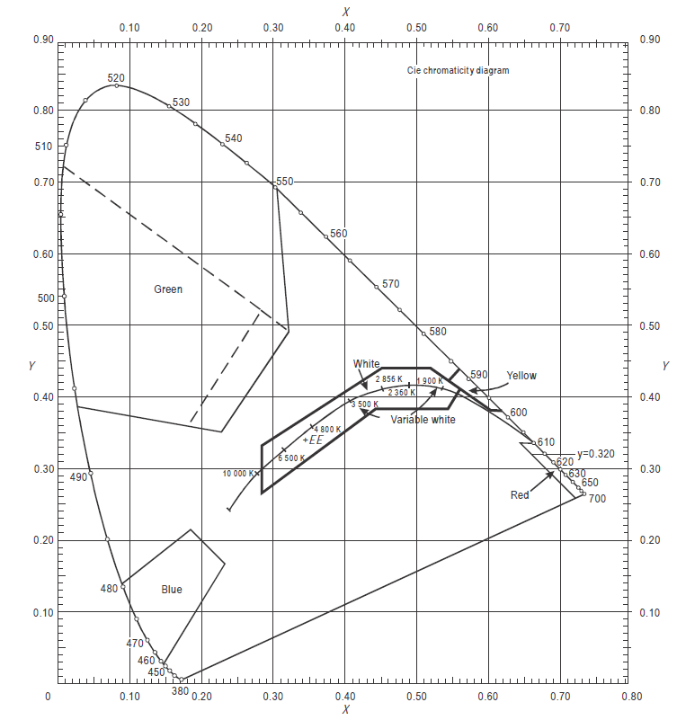
Figure U-1A. Colours for aeronautical ground lights (filament-type lamps)
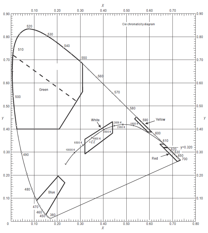
Figure U-1B. Colours for aeronautical ground lights (solid state lighting)
[Issue: ADR-DSN/3]
[Issue: ADR-DSN/4]
GM1 ADR-DSN.U.930 Colours for aeronautical ground lights
ED Decision 2017/021/R
(a)The chromaticity for ground lights with filament-type light sources, where dimming is not required, or where observers with defective colour vision should be able to determine the colour of the light, green signals should be within the following boundaries:
Yellow boundaryy = 0.726 – 0.726x
White boundaryx = 0.650y
Blue boundaryy = 0.390 – 0.171x
(b)Guidance on chromaticity changes resulting from the effect of temperature on filtering elements is given in ICAO Doc 9157, Aerodrome Design Manual, Part 4, Visual Aids.
(c)Where the colour signal is to be seen from long range, the current practice is to use colours within the boundaries specified in paragraph (a) above.
(d)For the chromaticity of ground lights with solid-state light sources, where observers with defective colour vision should be able to determine the colour of the light, green signals should be within the following boundaries:
Yellow boundaryy = 0.726 – 0.726x
White boundaryx = 0.625y – 0.041
Blue boundaryy = 0.400
(e)For the chromaticity of ground lights having a solid state light source, in order to avoid a large variation of shades of green, and if colours within the boundaries below are selected, colours within the boundaries specified in paragraph (d) above should not be used:
Yellow boundaryx= 0.310
White boundaryx = 0.625y – 0.041
Blue boundaryy = 0.726 – 0.726x
(f)Colour measurement for filament-type and solid state-type light sources:
(1)for the outermost isocandela curve, a measurement of colour coordinates should be made and recorded for review and judgement of acceptability; and
(2)certain light units may have an application so that they may be viewed and used by pilots from directions beyond that of the outermost isocandela curve (e.g. stop bar lights at significantly wide runway-holding positions); then an assessment of the actual application should be conducted and, if necessary, a check of colour shift at angular ranges beyond the outermost curve carried out.
[Issue: ADR-DSN/3]
[Issue: ADR-DSN/4]
CS ADR-DSN.U.935 Colours for markings, signs and panels
ED Decision 2022/006/R
(a)The specifications in surface colours given below apply only to freshly coloured surfaces. Colours used for markings, signs, and panels usually change with time and, therefore, require renewal.
(b)The specifications in paragraph (f) below for internally illuminated panels are interim in nature and are based on the CIE specifications for internally illuminated signs. It is intended that these specifications should be reviewed and updated as and when CIE develops specifications for internally illuminated panels.
(c)The chromaticities and luminance factors of ordinary colours, colours of retroreflective materials, and colours of internally illuminated signs and panels should be determined under the following standard conditions:
(1)angle of illumination: 45°;
(2)direction of view: perpendicular to surface; and
(3)illuminant: CIE standard illuminant D65.
(d)The chromaticity and luminance factors of ordinary colours for markings and externally illuminated signs and panels should be within the following boundaries when determined under standard conditions.
CIE Equations (see Figure U-2):
(1)Red
Purple boundaryy = 0.345 – 0.051x
White boundaryy = 0.910 – x
Orange boundaryy = 0.314 + 0.047x
Luminance factorβ = 0.07 (minimum)
(2)Orange
Red boundaryy = 0.285 + 0.100x
White boundaryy = 0.940 – x
Yellow boundaryy = 0.250 + 0.220x
Luminance factorβ = 0.20 (minimum)
(3)Yellow
Orange boundaryy = 0.108 + 0.707x
White boundaryy = 0.910 – x
Green boundaryy = 1.35x – 0.093
Luminance factorβ = 0.45 (minimum)
(4)White
Purple boundaryy = 0.010 + x
Blue boundaryy = 0.610 – x
Green boundaryy = 0.030 + x
Yellow boundaryy = 0.710 – x
Luminance factorβ = 0.75 (minimum)
(5)Black
Purple boundaryy = x – 0.030
Blue boundaryy = 0.570 – x
Green boundaryy = 0.050 + x
Yellow boundaryy = 0.740 – x
Luminance factorβ = 0.03 (maximum)
(6)Yellowish green
Green boundaryy = 1.317x + 0.4
White boundary y = 0.910 – x
Yellow boundaryy = 0.867x + 0.4
(7)Green
Yellow boundary x = 0.313
White boundary y = 0.243 + 0.670x
Blue boundaryy = 0.493 – 0.524x
Luminance factor β = 0.10 (minimum)
The small separation between surface red and surface orange is not sufficient to ensure the distinction of these colours when seen separately.
(e)The chromaticity and luminance factors of colours of retroreflective materials for markings, signs, and panels should be within the following boundaries when determined under standard conditions.
CIE Equations (see Figure U-3):
(1)Red
Purple boundaryy = 0.345 – 0.051x
White boundaryy = 0.910 – x
Orange boundaryy = 0.314 + 0.047x
Luminance factorβ = 0.03 (minimum)
(2)Orange
Red boundaryy = 0.265 + 0.205x
White boundaryy = 0.910 – x
Yellow boundaryy = 0.207 + 0.390x
Luminance factorβ = 0.14 (minimum)
(3)Yellow
Orange boundaryy = 0.160 + 0.540x
White boundaryy = 0.910 – x
Green boundaryy = 1.35x – 0.093
Luminance factorβ = 0.16 (minimum)
(4)White
Purple boundaryy = x
Blue boundaryy = 0.610 – x
Green boundaryy = 0.040 + x
Yellow boundaryy = 0.710 – x
Luminance factorβ = 0.27 (minimum)
(5)Blue
Green boundaryy = 0.118 + 0.675x
White boundary y = 0.370 – x
Purple boundaryy = 1.65x – 0.187
Luminance factorβ = 0.01 (minimum)
(6)Green
Yellow boundaryy = 0.711 – 1.22x
White boundaryy = 0.243 + 0.670x
Blue boundaryy = 0.405 – 0.243x
Luminance factorβ = 0.03 (minimum)
(f)The chromaticity and luminance factors of colours for luminescent or internally illuminated signs and panels should be within the following boundaries when determined under standard conditions.
CIE Equations (see Figure U-4):
(1)Red
Purple boundaryy = 0.345 – 0.051x
White boundaryy = 0.910 – x
Orange boundaryy = 0.314 + 0.047x
Luminance factor
(day condition)β = 0.07 (minimum)
Relative luminance
to white (night condition)5 % (minimum)20 % (max)
(2)Yellow
Orange boundaryy = 0.108 + 0.707x
White boundaryy = 0.910 – x
Green boundaryy = 1.35x – 0.093
Luminance factor
(day condition)β = 0.45 (minimum)
Relative luminance
to white (night condition)30 % (minimum)80 % (max)
(3)White
Purple boundaryy = 0.010 + x
Blue boundaryy = 0.610 – x
Green boundaryy = 0.030 + x
Yellow boundaryy = 0.710 – x
Luminance factor
(day condition)β = 0.75 (minimum)
Relative luminance
to white (night conditions)100 %
(4)Black
Purple boundaryy = x – 0.030
Blue boundaryy = 0.570 – x
Green boundaryy = 0.050 + x
Yellow boundaryy = 0.740 – x
Luminance factor
(day condition)β = 0.03 (max)
Relative luminance
to white (night condition)0 % (minimum)2 % (maximum)
(5)Green
Yellow boundaryx = 0.313
White boundaryy = 0.243 + 0.670x
Blue boundaryy = 0.493 – 0.524x
Luminance factor
(day conditions)β = 0.10 minimum
Relative luminance
to white (night conditions)5 % (minimum)30 % (maximum)
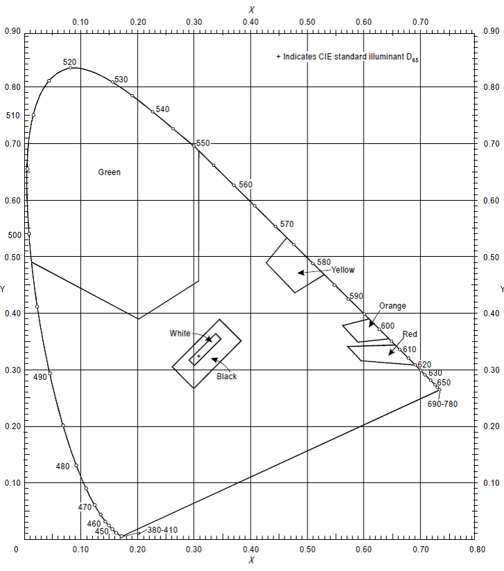
Figure U-2. Ordinary colours for markings and externally illuminated signs and panels
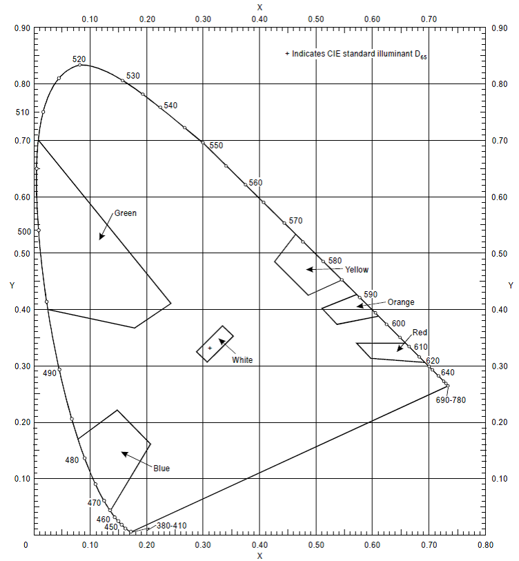
Figure U-3. Colours of retroreflective materials for markings, signs and panels
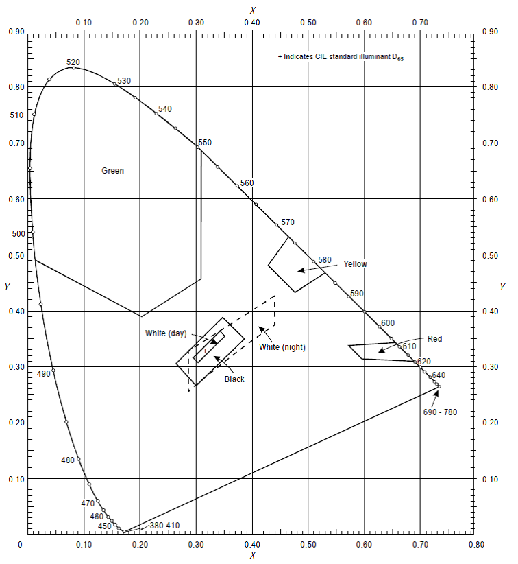
Figure U-4. Colours of luminescent or internally illuminated signs and panels
[Issue: ADR-DSN/3]
[Issue: ADR-DSN/6]
GM1 ADR-DSN.U.935 Colours for markings, signs and panels
ED Decision 2014/013/R
intentionally left blank
CS ADR-DSN.U.940 Aeronautical ground light characteristics
ED Decision 2025/004/R
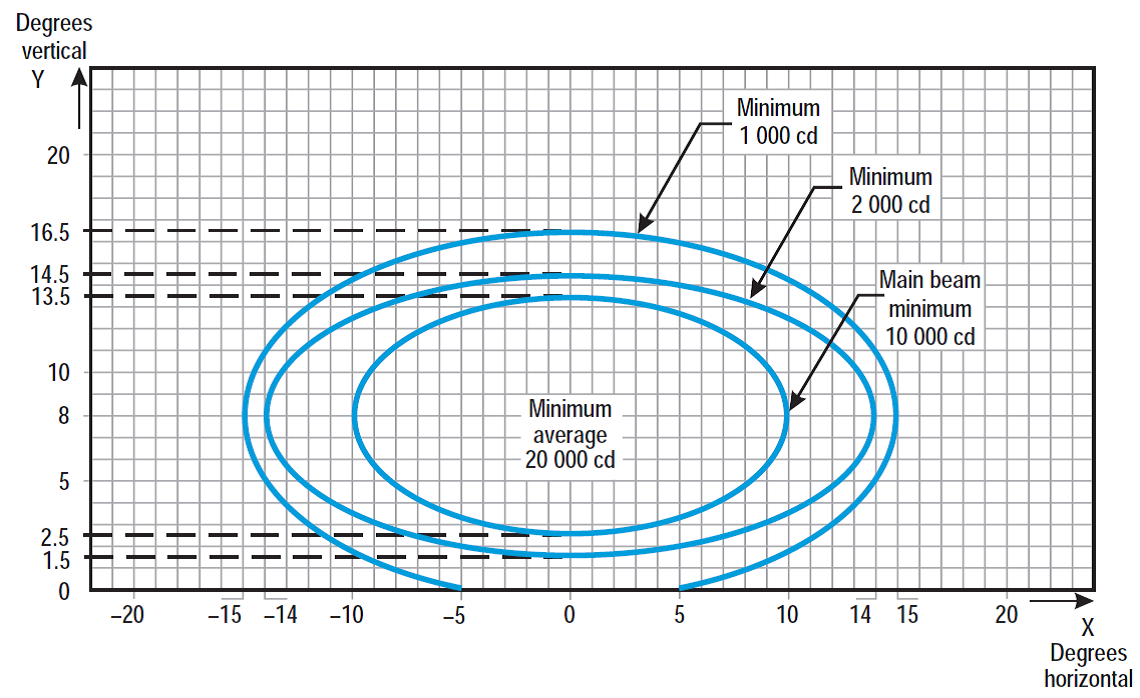
Figure U-5. Isocandela diagram for approach centre line light and crossbars (white light)
Notes:
(a)Curves calculated on formula
a | 10 | 14 | 15 |
b | 5.5 | 6.5 | 8.5 |
(b)Vertical setting angles of the lights should be such that the following vertical coverage of the main beam should be met:
distance from threshold | vertical main beam coverage |
threshold to 315 m | 0° - 11° |
316 m to 475 m | 0.5° - 11.5° |
476 m to 640 m | 1.5° - 12.5° |
641 m and beyond | 2.5° -13.5° (as illustrated above) |
(c)Lights in crossbars beyond 22.5 m from the centre line should be toed-in 2 degrees. All other lights should be aligned parallel to the centre line of the runway.
(d)See collective notes for Figures U-5 to U-15.
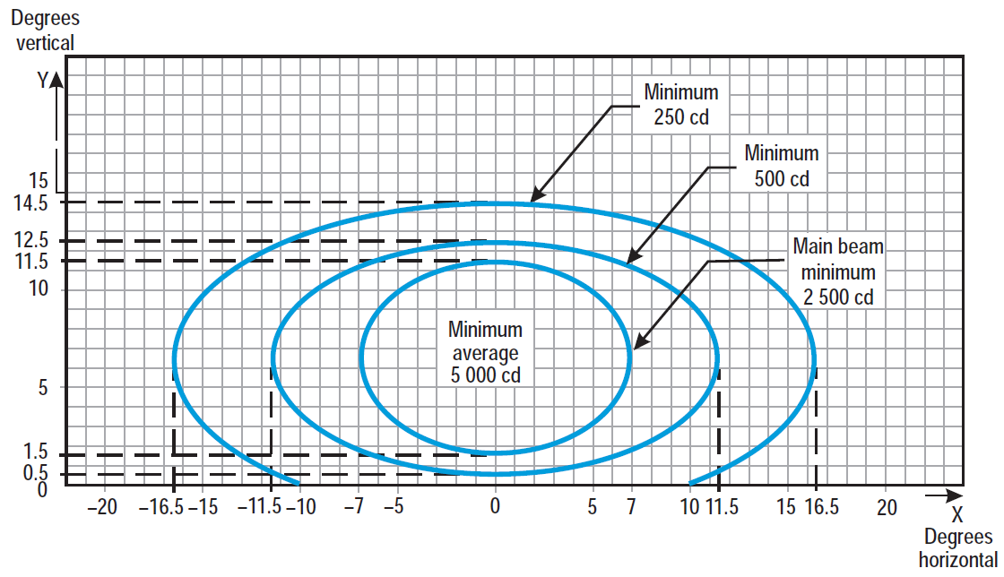
Figure U-6. Isocandela diagram for approach side row light (red light)
Notes:
(a)Curves calculated on formula
a | 7.0 | 11.5 | 16.5 |
b | 5.0 | 6.0 | 8.0 |
(b)Toe-in 2 degrees
(c)Vertical setting angles of the lights should be such that the following vertical coverage of the main beam should be met:
distance from threshold | vertical main beam coverage |
threshold to 115 m | 0.5° - 10.5° |
116 m to 215 m | 1° - 11° |
216 m and beyond | 1.5° - 11.5° (as illustrated above) |
(d)See collective notes for Figures U-5 to U-15.
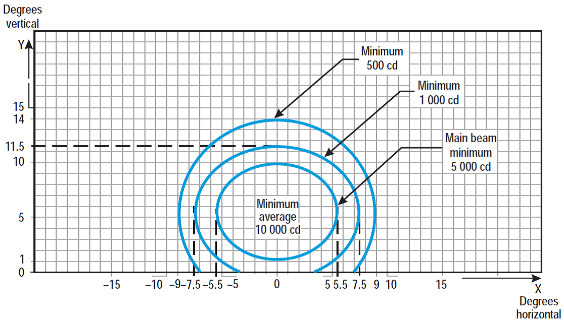
Figure U-7. Isocandela diagram for threshold light (green light)
Notes:
(a)Curves calculated on formula
a | 5.5 | 7.5 | 9.0 |
b | 4.5 | 6.0 | 8.5 |
(b)Toe-in 3.5 degrees
(c)See collective notes for Figures U-5 to U-15.
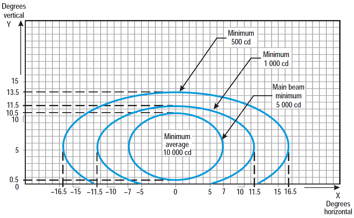
Figure U-8. Isocandela diagram for threshold wing bar light (green light)
Notes:
(a)Curves calculated on formula
a | 7.0 | 11.5 | 16.5 |
b | 5.0 | 6.0 | 8.0 |
(b)Toe-in 2 degrees
(c)See collective notes for Figures U-5 to U-15.
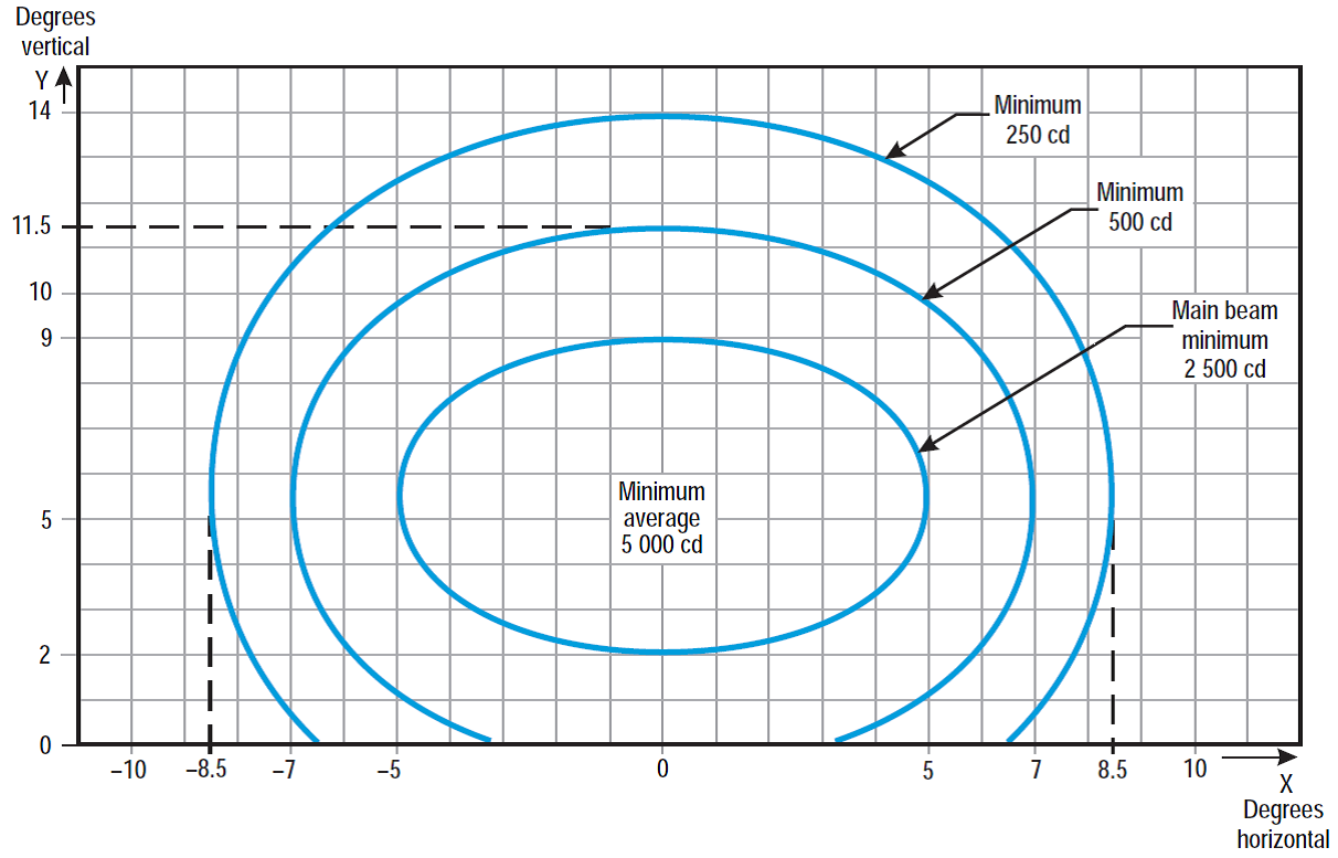
Figure U-9. Isocandela diagram for touchdown zone light (white light)
Notes:
(a)Curves calculated on formula
a | 5.0 | 7.0 | 8.5 |
b | 3.5 | 6.0 | 8.5 |
(b)Toe-in 4 degrees
(c)See collective notes for Figures U-5 to U-15.
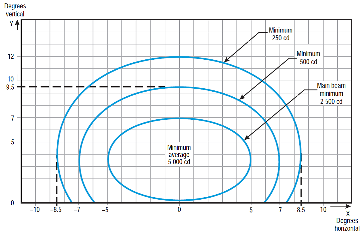
Figure U-10. Isocandela diagram for runway centre line light with 30 m longitudinal spacing (white light) and rapid exit taxiway indicator light (yellow light)
Notes:
(a)Curves calculated on formula
a | 5.0 | 7.0 | 8.5 |
b | 3.5 | 6.0 | 8.5 |
(b)For red light, multiply values by 0.15.
(c)For yellow light, multiply values by 0.40.
(d)See collective notes for Figures U-5 to U-15.
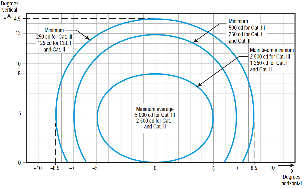
Figure U-11. Isocandela diagram for runway centre line light with 15 m longitudinal spacing (white light) and rapid exit taxiway indicator light (yellow light)
Notes:
(a)Curves calculated on formula
a | 5.0 | 7.0 | 8.5 |
b | 4.5 | 8.5 | 10 |
(b)For red light, multiply values by 0.15.
(c)For yellow light, multiply values by 0.40.
(d)See collective notes for Figures U-5 to U-15.
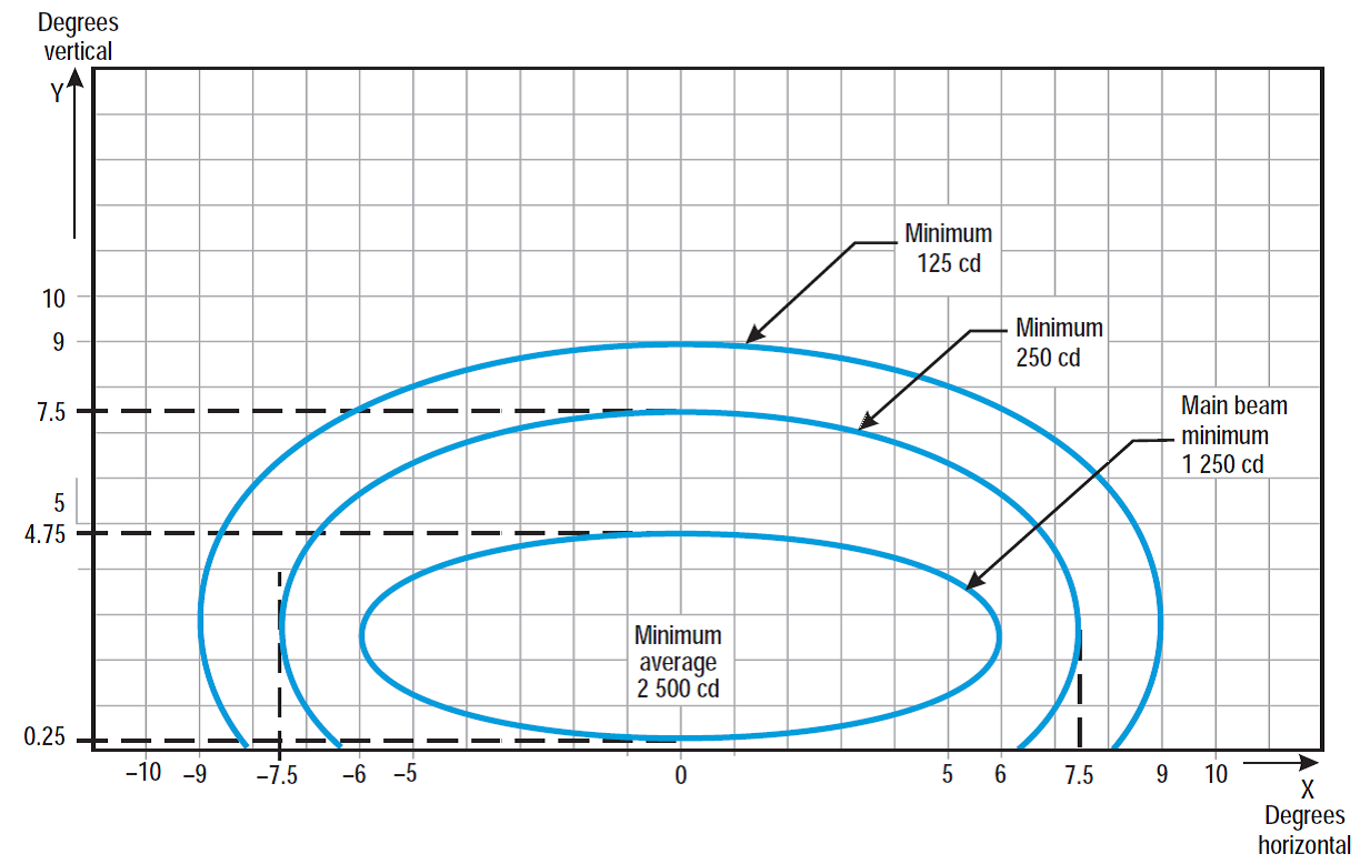
Figure U-12. Isocandela diagram for runway end light (red light)
Notes:
(a)Curves calculated on formula
a | 6.0 | 7.5 | 9.0 |
b | 2.25 | 5.0 | 6.5 |
(b)See collective notes for Figures U-5 to U-15.
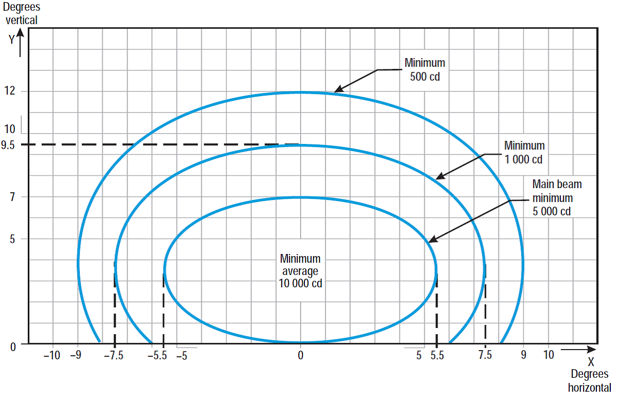
Figure U-13. Isocandela diagram for runway edge light where width of runway is 45 m (white light)
Notes:
(a)Curves calculated on formula
a | 5.5 | 7.5 | 9.0 |
b | 3.5 | 6.0 | 8.5 |
(b)Toe-in 3.5 degrees
(c)For red light, multiply values by 0.15.
(d)For yellow light, multiply values by 0.40.
(e)See collective notes for Figures U-5 to U-15.
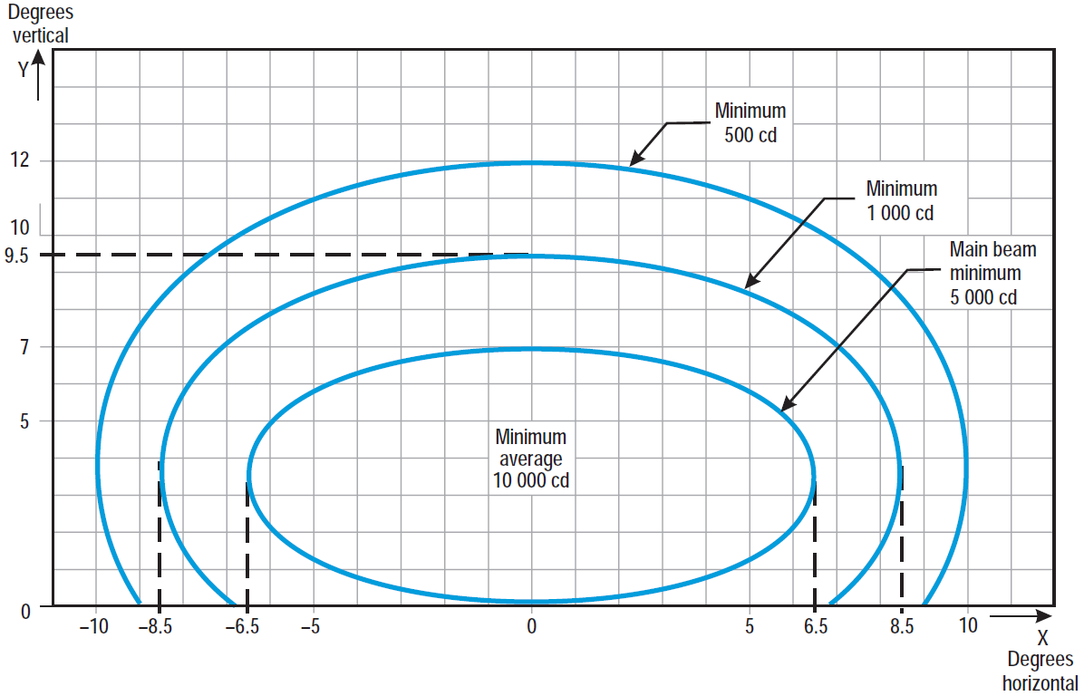
Figure U-14. Isocandela diagram for runway edge light where width of runway is 60 m (white light)
Notes:
(a)Curves calculated on formula
a | 6.5 | 8.5 | 10.0 |
b | 3.5 | 6.0 | 8.5 |
(b)Toe-in 4.5 degrees
(c)For red light, multiply values by 0.15.
(d)For yellow light, multiply values by 0.40.
(e)See collective notes for Figures U-5 to U-15.
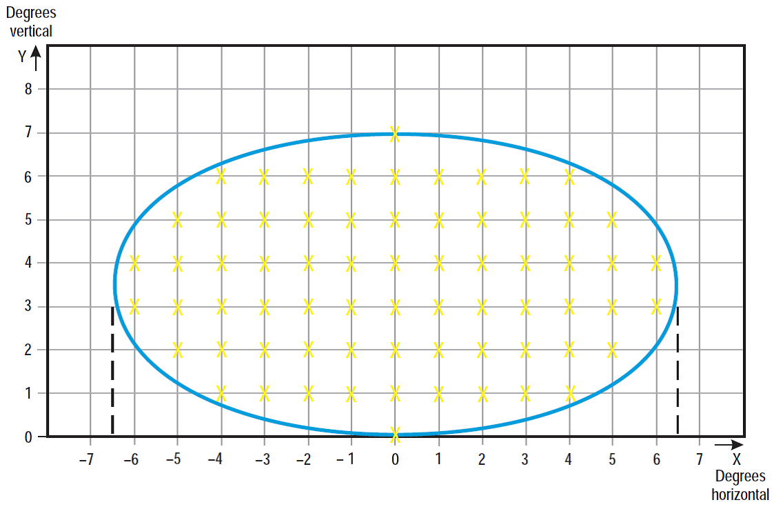
Figure U-15. Grid points to be used for the calculation of average intensity of approach and runway lights
Collective notes to Figures U-5 to U-15
(a)The ellipses in each Figure are symmetrical about the common vertical and horizontal axes.
(b)Figures U-5 to U-14 show the minimum allowable light intensities. The average intensity of the main beam is calculated by establishing grid points as shown in Figure U-15 and using the intensity value measures at all grid points located within and on the perimeter of the ellipse representing the main beam. The average value is the arithmetic average of light intensities measured at all considered grid points.
(c)No deviations are acceptable in the main beam pattern when the lighting fixture is properly aimed.
(d)Average intensity ratio. The ratio between the average intensity within the ellipse defining the main beam of a typical new light and the average light intensity of the main beam of a new runway edge light should be as follows:
Figure U-5 | Approach centre line and crossbars | 1.5 to 2.0 | (white light) |
Figure U-6 | Approach side row | 0.5 to 1.0 | (red light) |
Figure U-7 | Threshold | 1.0 to 1.5 | (green light) |
Figure U-8 | Threshold wing bar | 1.0 to 1.5 | (green light) |
Figure U-9 | Touchdown zone | 0.5 to 1.0 | (white light) |
Figure U-10 | Runway centre line (longitudinal spacing 30 m) | 0.5 to 1.0 | (white light) |
Figure U-11 | Runway centre line (longitudinal spacing 15 m) | 0.5 to 1.0 for CAT III | (white light) |
0.25 to 0.5 for CAT I, II | (white light) | ||
Figure U-12 | Runway end | 0.25 to 0.5 | (red light) |
Figure U-13 | Runway edge (45 m runway width) | 1.0 | (white light) |
Figure U-14 | Runway edge (60 m runway width) | 1.0 | (white light) |
(e)The beam coverages in the Figures provide the necessary guidance for approaches down to an RVR of the order of 150 m and take-offs down to an RVR of the order of 100 m.
(f)Horizontal angles are measured with respect to the vertical plane through the runway centre line. For lights other than centre line lights, the direction towards the runway centre line is considered positive. Vertical angles are measured with respect to the horizontal plane.
(g)Where, for approach centre line lights and crossbars and for approach side row lights, inset lights are used in lieu of elevated lights, e.g. on a runway with a displaced threshold, the intensity requirements can be met by installing two or three fittings (lower intensity) at each position.
(h)The importance of adequate maintenance cannot be overemphasised. The average intensity should never fall to a value less than 50 % of the value shown in the Figures, and it should be the aim of aerodrome operator to maintain a level of light output close to the specified minimum average intensity.
(i)The light unit should be installed so that the main beam is aligned within one-half degree of the specified.
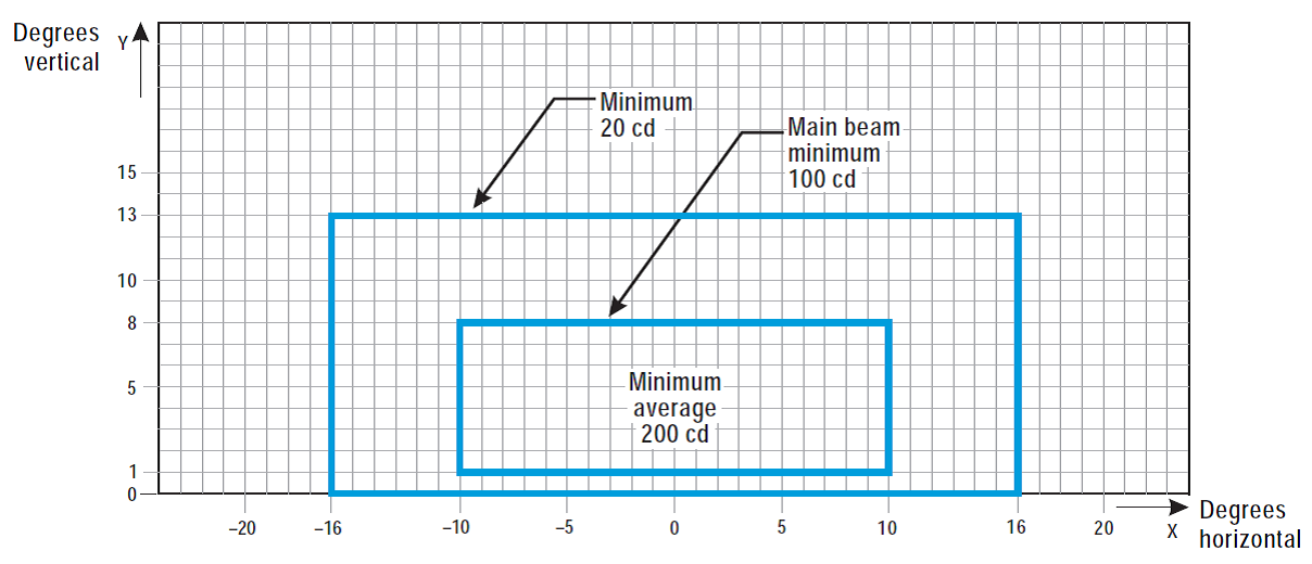
Figure U-16. Isocandela diagram for taxiway centre line (15 m spacing), RELs, no-entry bar, and stop bar lights in straight sections intended for use in runway visual range conditions of less than a value of 350 m where large offsets can occur and for low-intensity runway guard lights, Configuration B
Notes:
(a)These beam coverages allow for displacement of the cockpit from the centre line up to distances of the order of 12 m and are intended for use before and after curves.
(b)See collective notes for Figures U-16 to U-25.
(c)Increased intensities for enhanced rapid exit taxiway centre line lights are four times the respective intensities in the figure (i.e. 800 cd for minimum average main beam).
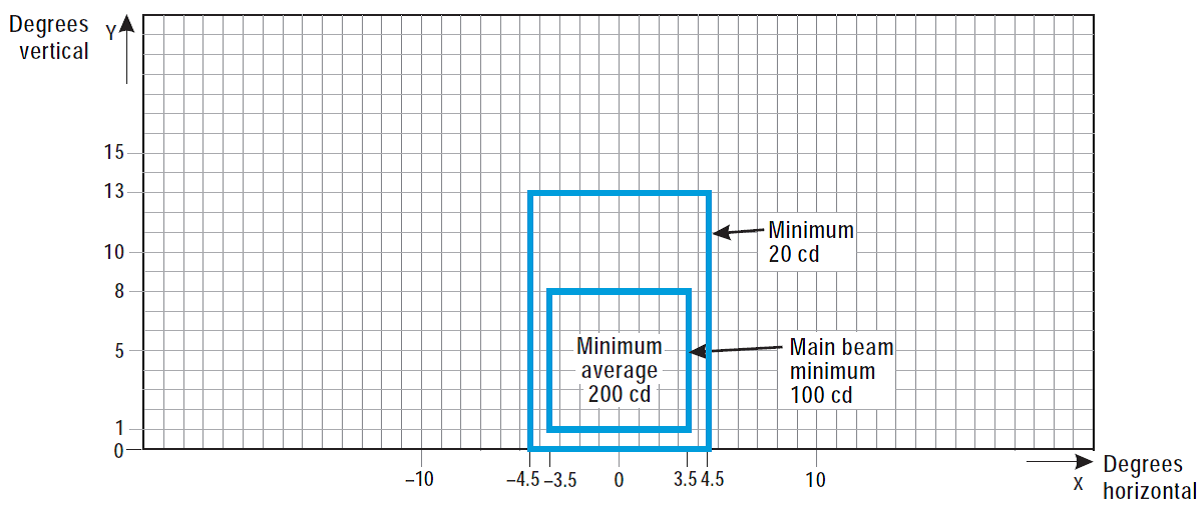
Figure U-17. Isocandela diagram for taxiway centre line (15 m spacing), no-entry bar, and stop bar lights in straight sections intended for use in runway visual range conditions of less than a value of 350 m
Notes:
(a)These beam coverages are generally satisfactory and cater for a normal displacement of the cockpit from the centre line of approximately 3 m.
(b)See collective notes for Figures U-16 to U-25.
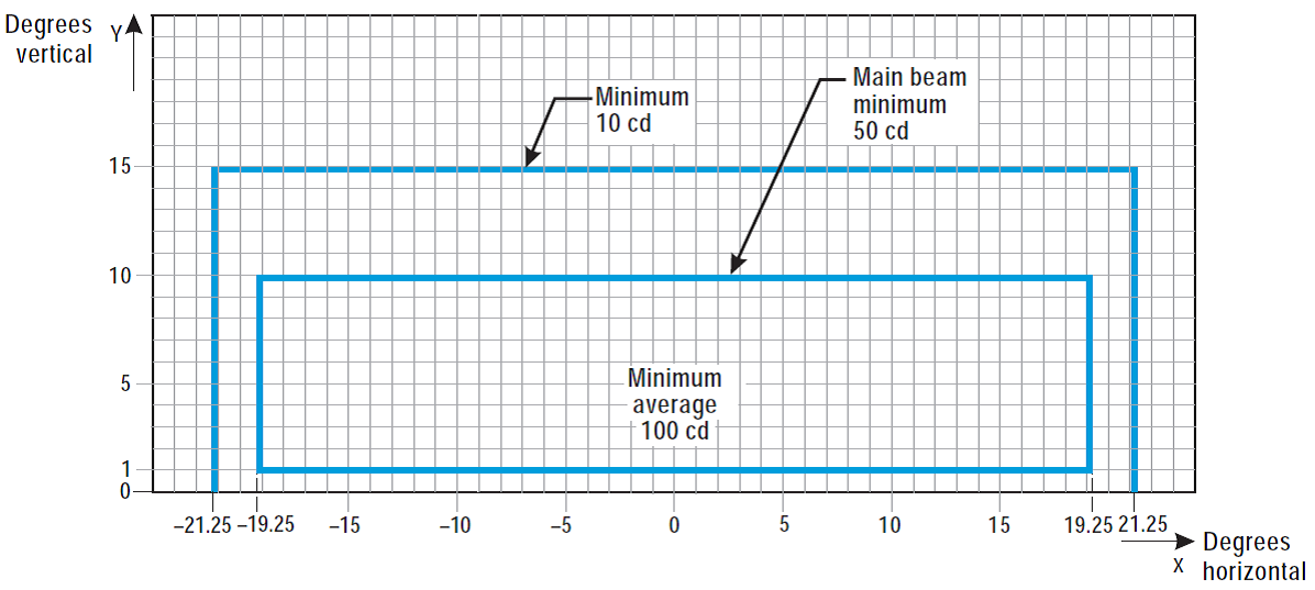
Figure U-18. Isocandela diagram for taxiway centre line (7.5 m spacing), RELs, no-entry bar, and stop bar lights in curved sections intended for use in runway visual range conditions of less than a value of 350 m
Notes:
(a)Lights on curves to be toed-in 15.75 degrees with respect to the tangent of the curve. This does not apply to RELs.
(b)Where provided, increased intensities for RELs should be twice the specified intensities, i.e. minimum 20 cd, main beam minimum 100 cd, and minimum average 200 cd.
(c)See collective notes for Figures U-16 to U-25.
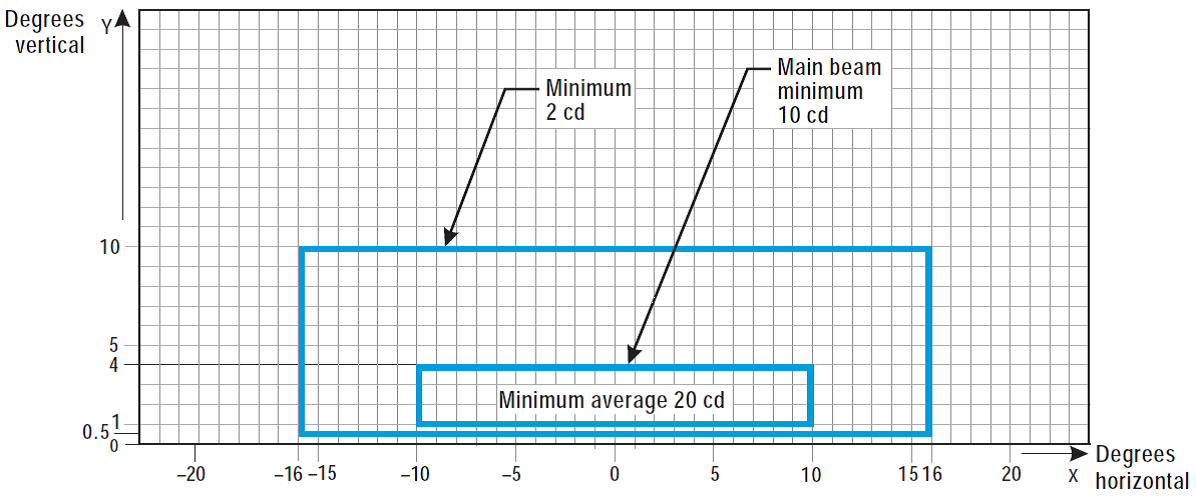
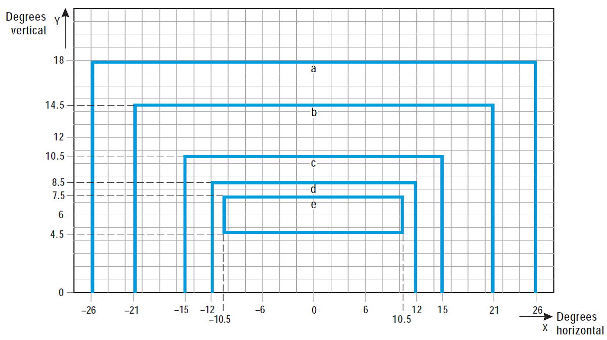
Figure U-19. Isocandela diagram for taxiway centre line (30 m, 60 m spacing), no-entry bar, and stop bar lights in straight sections intended for use in runway visual range conditions of 350 m or greater
Notes:
(a)At locations where high background luminance is usual, and where deterioration of light output resulting from dust, snow, and local contamination is a significant factor, the cd-values should be multiplied by 2.5.
(b)Where omnidirectional lights are used they should comply with the vertical beam requirements in this Figure.
(c)See collective notes for Figures U-16 to U-25.
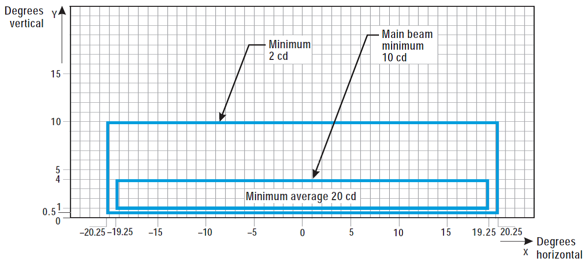
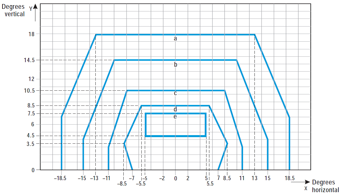
Figure U-20. Isocandela diagram for taxiway centre line (7.5 m, 15 m, 30 m spacing), no-entry bar, and stop bar lights in curved sections intended for use in runway visual range conditions of 350 m or greater
Notes:
(a)Lights on curves to be toed-in 15.75 degrees with respect to the tangent of the curve.
(b)At locations where high background luminance is usual and where deterioration of light output resulting from dust, snow and, local contamination is a significant factor, the cd-values should be multiplied by 2.5.
(c)These beam coverages allow for displacement of the cockpit from the centre line up to distances of the order of 12 m as could occur at the end of curves.
(d)See collective notes for Figures U-16 to U-25.
Curve | a | b | c | d | e |
Intensity (cd) | 8 | 20 | 100 | 450 | 1800 |
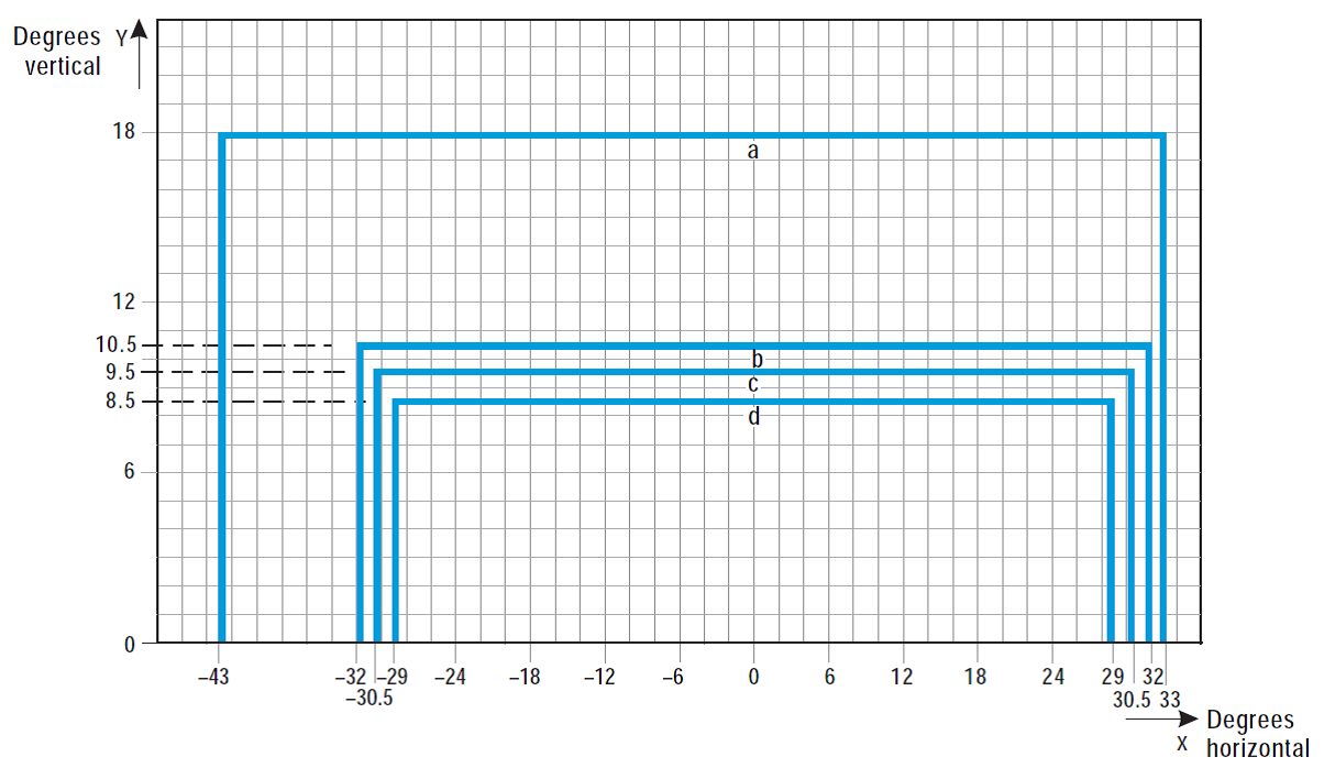
Figure U-21. Isocandela diagram for high-intensity taxiway centre line (15 m spacing), no-entry bar, and stop bar lights in straight sections intended for use in an advanced surface movement guidance and control system where higher light intensities are required and where large offsets can occur.
Notes:
(a)These beam coverages are generally satisfactory and cater for a normal displacement of the cockpit corresponding to the outer main gear wheel on the taxiway edge.
(b)See collective notes for Figures U-16 to U-25.
Curve | a | b | c | d | e |
Intensity (cd) | 8 | 20 | 100 | 450 | 1800 |
Figure U-22. Isocandela diagram for high-intensity taxiway centre line (15 m spacing), no-entry bar, and stop bar lights in straight sections intended for use in an advanced surface movement guidance and control system where higher light intensities are required
Notes:
(a)These beam coverages are generally satisfactory and cater for a normal displacement of the cockpit corresponding to the outer main gear wheel on the taxiway edge.
(b)See collective notes for Figures U-16 to U-25.
Curve | a | b | c | d |
Intensity (cd) | 8 | 100 | 200 | 400 |
Figure U-23. Isocandela diagram for high-intensity taxiway centre line (7.5 m spacing), no-entry bar, and stop bar lights in curved sections intended for use in an advanced surface movement guidance and control system where higher light intensities are required
Notes:
(a)Lights on curves to be toed-in 17 degrees with respect to the tangent of the curve.
(b)See collective notes for Figures U-16 to U-25.
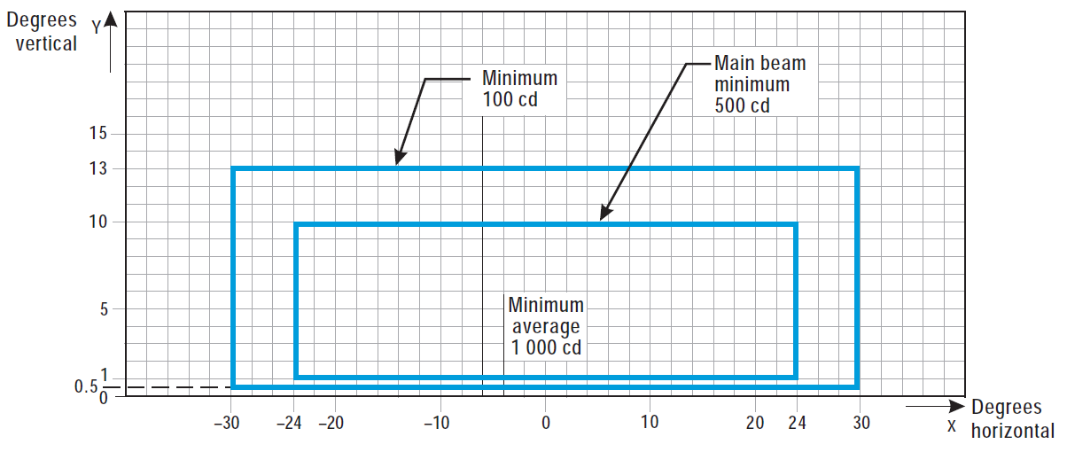
Figure U-24. Isocandela diagram for high-intensity runway guard lights, Configuration B
Notes:
(a)Although the lights flash in normal operation, the light intensity is specified as if the lights were fixed for incandescent lamps.
(b)See collective notes for Figures U-16 to U-25.
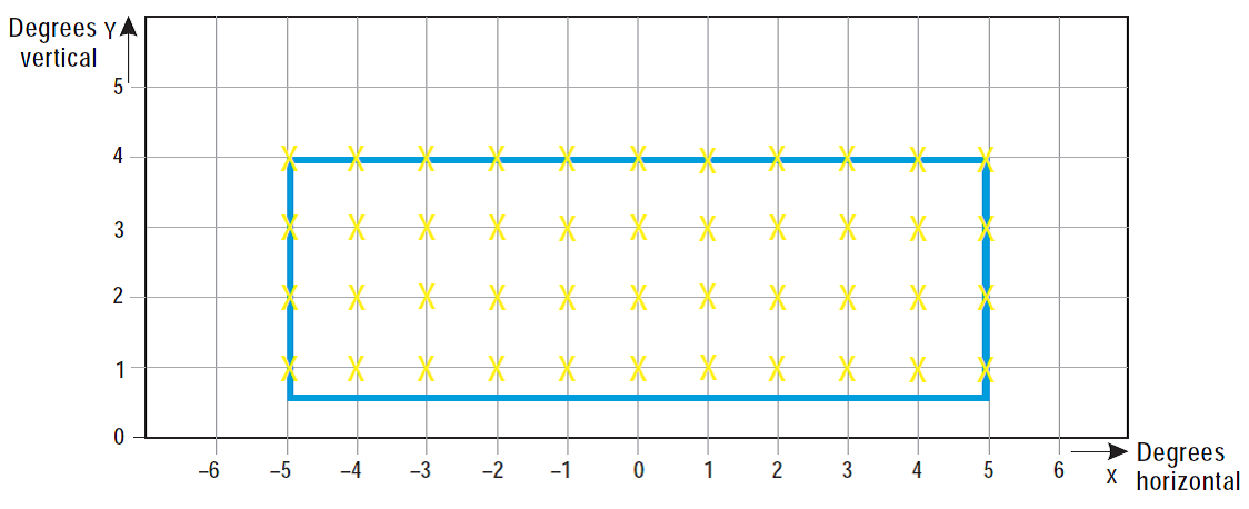
Figure U-25. Grid points to be used for calculation of average intensity of taxiway centre line and stop bar lights
Collective notes to Figures U-16 to U-25:
(a)The intensities specified in Figures U-16 to U-24 are in green and yellow light for taxiway centre line lights, yellow light for runway guard lights, and red light for stop bar lights.
(b)Figures U-16 to U-24 show the minimum allowable light intensities. The average intensity of the main beam is calculated by establishing grid points as shown in Figure U-25, and using the intensity values measured at all grid points located within and on the perimeter of the rectangle representing the main beam. The average value is the arithmetic average of the light intensities measured at all considered grid points.
(c)No deviations are acceptable in the main beam or in the innermost beam as applicable, when the lighting fixture is properly aimed.
(d)Horizontal angles are measured with respect to the vertical plane through the taxiway centre line, except on curves where they are measured with respect to the tangent to the curve.
(e)Vertical angles are measured from the longitudinal slope of the taxiway surface.
(f)The importance of adequate maintenance cannot be overemphasised. The intensity, either average where applicable or as specified on the corresponding isocandela curves, should never fall to a value less than 50 % of the value shown in the figures, and it should be the aim of aerodrome operator to maintain a level of light output close to the specified minimum average intensity.
(g)The light unit should be installed so that the main beam or the innermost beam as applicable, is aligned within one-half degree of the specified requirement.
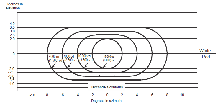
Figure U-26. Light intensity distribution of PAPI and APAPI
Notes:
(a)These curves are for minimum intensities in red light.
(b)The intensity value in the white sector of the beam is no less than 2 and may be as high as 6.5 times the corresponding intensity in the red sector.
(c)The intensity values shown in brackets are for APAPI.
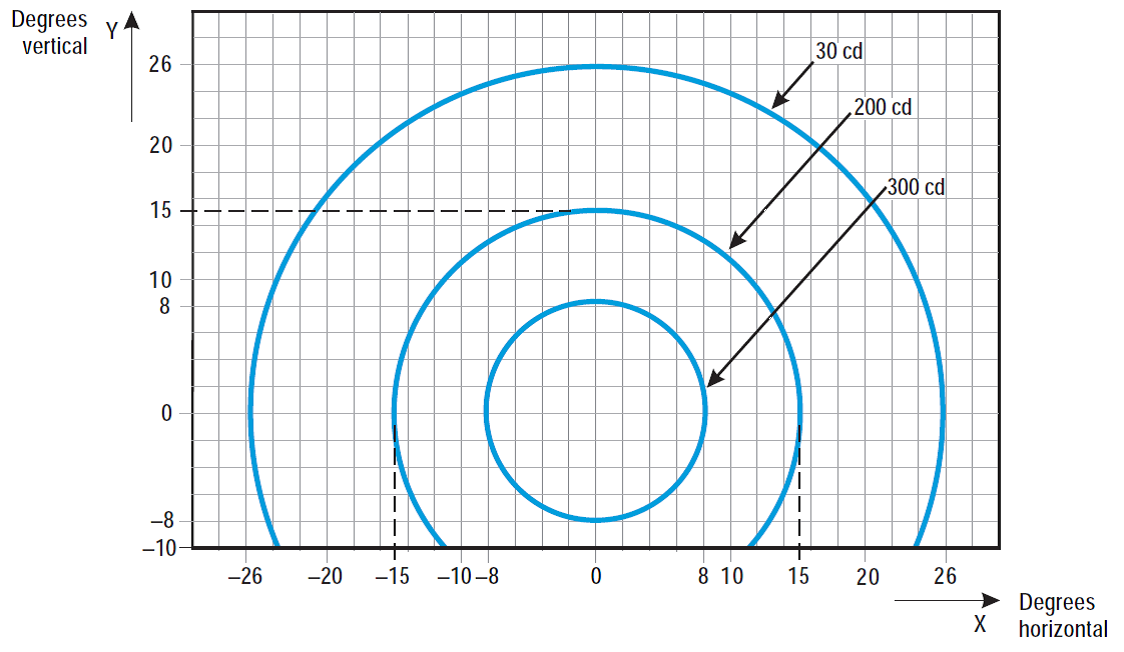
Figure U-27. Isocandela diagram for each light in low-intensity runway guard lights, Configuration A
Notes:
(a)Although the lights flash in normal operation, the light intensity is specified as if the lights were fixed for incandescent lamps.
(b)The intensities specified are in yellow light.
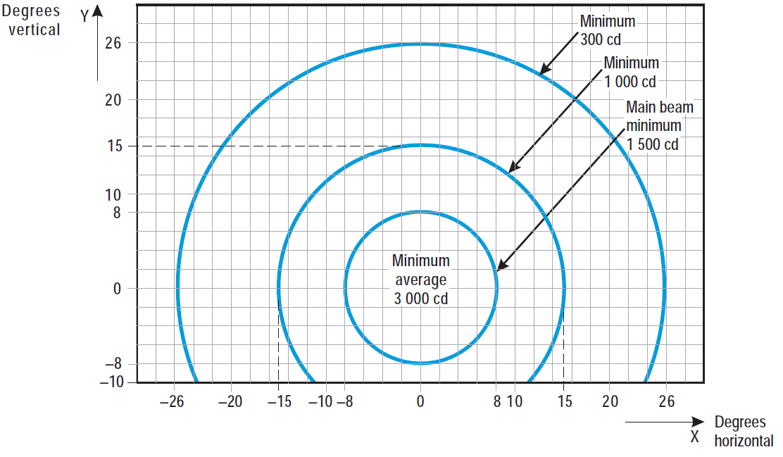
Figure U-28. Isocandela diagram for each light in high-intensity runway guard lights, Configuration A
Notes:
(a)Although the lights flash in normal operation, the light intensity is specified as if the lights were fixed for incandescent lamps.
(b)The intensities specified are in yellow light.
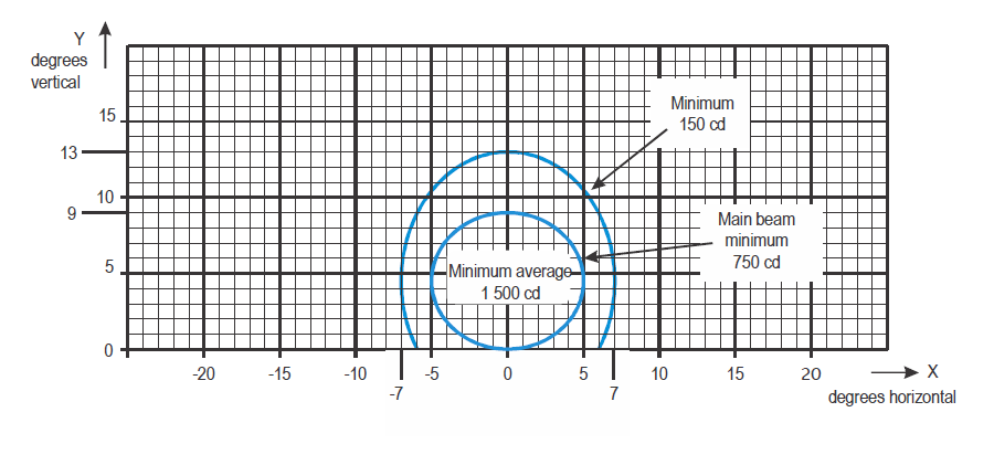
Figure U-29. Isocandela diagram for take-off and hold lights (THL) (red light)
Notes:
(a)Curves calculated on formula
a | 5.0 | 7.0 |
b | 4.5 | 8.5 |
(b)See collective notes for Figures U-5 to U-15 and Figure U-29
[Issue: ADR-DSN/3]
[Issue: ADR-DSN/4]
GM1 ADR-DSN.U.940 Aeronautical ground light characteristics
ED Decision 2014/013/R
intentionally left blank