
ED Decision 2019/012/R
(a) When a FATO has similar characteristics to a runway, the applicable CSs are provided in the paragraphs below entitled ‘runway-type FATO’.
(b) For all other types of FATO, the applicable CSs are provided in the paragraphs below entitled ‘All FATOs except runway-type FATOs’.
ED Decision 2019/012/R
When a runway is marked in accordance with the provisions of CS-ADR-DSN, and is utilised as a FATO, no additional runway markings or lighting are required for helicopter use.
CS HPT-DSN.F.510 Wind direction indicators
ED Decision 2019/012/R
Applicability: A heliport should be equipped with at least one wind direction indicator.
GM1 HPT-DSN.F.510 Wind direction indicators
ED Decision 2019/012/R
(a) General: If the wind direction indicators serving the aerodrome do not clearly indicate the correct wind information at the heliport, additional wind direction indicators should be installed in order to provide wind information to the pilot during approach and take-off.
(b) Location:
(1) A wind direction indicator should be located so as to indicate the wind conditions over the FATO and TLOF and in such a way as to be free from the effects of airflow disturbances caused by nearby objects or rotor downwash. It should be visible from a helicopter in flight, in a hover or on the movement area.
(2) Where a TLOF and/or FATO are subject to a disturbed airflow, additional wind direction indicators located close to the area should be provided to indicate the surface wind on the area.
(c) Characteristics:
(1) A wind direction indicator should give a clear indication of the direction of the wind and a general indication of the wind speed.
(2) A wind direction indicator for the heliport should be a truncated cone made of lightweight fabric and should have the following minimum dimensions:
(i) Length 2.4 m,
(ii) Diameter (larger end) 0.6 m, and
(iii) Diameter (smaller end) 0.3 m.
(3) The colour of the wind direction indicator should be so selected as to make it clearly visible and understandable from a height of at least 200 m (650 ft) above the heliport, having regard to the background:
(i) where practicable, a single colour, preferably white or orange, should be used;
(ii) where a combination of two colours is required to give adequate conspicuity against changing backgrounds, they should preferably be orange and white, red and white, or black and white, and should be arranged in five alternate bands, the first and last band being the darker colour.
(d) A wind direction indicator at a heliport intended for use at night should be illuminated.
CS HPT-DSN.F.520 Heliport identification marking
ED Decision 2019/012/R
(a) Applicability: Heliport identification markings should be provided at a heliport.
(b) Location:
(1) For runway-type FATOs:
A heliport identification marking should be located in the FATO and when used in conjunction with FATO designation markings, should be displayed at each end of the FATO (see Figure F-2).
(2) For all FATOs except runway-type FATOs:
(i) A heliport identification marking should be located at or near the centre of the FATO (see Figure F-1).
(ii) On a FATO which contains a TLOF, a heliport identification marking should be located in the FATO so that the position of it coincides with the centre of the TLOF.
(c) Characteristics:
(1) A heliport identification marking should consist of a letter ‘H’, white in colour. The dimensions of the ‘H’ marking should be no less than those shown in Figure F-3.
(2) Where the ‘H’ marking is used for a runway-type FATO, its dimensions should be increased by a factor of 3 (see Figures F-2 and F-3).
(3) A heliport identification marking should be oriented with the cross arm of the ‘H’ at right angles to the preferred final approach direction.
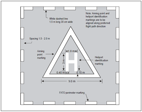
Note: The aiming point, heliport identification and FATO perimeter markings are white and may be edged with a 10 cm black border to improve contrast
Figure F-1. Combined heliport identification, aiming point and FATO perimeter marking
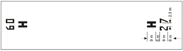
Figure F-2. FATO designation marking and heliport identification marking for a runway-type FATO
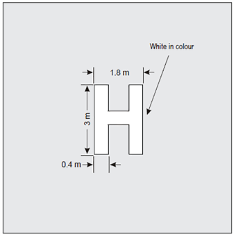
Figure F-3. Heliport identification marking
GM1 HPT-DSN.F.520 Heliport identification marking
ED Decision 2019/012/R
On a FATO which does not contain a TLOF and which is marked with an aiming point marking (see CS HPT-DSN.F.550) the heliport identification marking should be established in the centre of the aiming point marking as shown in Figure F-1.
CS HPT-DSN.F.530 Final approach and take-off area perimeter marking or markers
ED Decision 2019/012/R
(a) Applicability: FATO perimeter marking or markers should be provided where the extent of the FATO is not self-evident.
(b) Location: The FATO perimeter marking or markers should be located on the edge of the FATO.
(c) Characteristics:
(1) For runway-type FATOs:
(i) The perimeter of the FATO should be defined with markings or markers spaced at equal intervals of not more than 50 m with at least three markings or markers on each side including a marking or marker at each corner.
(ii) A FATO perimeter marking should be a rectangular stripe with a length of 9 m or one-fifth of the side of the FATO which it defines and a width of 1 m.
(iii) FATO perimeter markings should be white.
(iv) FATO perimeter markers should be of a colour (or colours) that contrasts (contrast) effectively against the operating background.
(2) For all FATOs except runway-type FATOs:
(i) For an unpaved FATO, the perimeter should be defined with flush in-ground markers. The FATO perimeter markers should be 30 cm in width, 1.5 m in length, and with end-to-end spacing of not less than 1.5 m and not more than 2 m. The corners of a square or rectangular FATO should be defined.
(ii) For a paved FATO, the perimeter should be defined with a dashed line. The FATO perimeter marking segments should be 30 cm in width, 1.5 m in length, and with end-to-end spacing of not less than 1.5 m and not more than 2 m. The corners of the square or rectangular FATO should be defined.
(iii) FATO perimeter markings and flush in-ground markers should be white.
GM1 HPT-DSN.F.530 Final approach and take-off area perimeter marking or markers
ED Decision 2019/012/R
(a) Where a TLOF is coincident with a FATO, the TLOF marking can be used.
(b) FATO perimeter markers should be of a single colour, either orange or red, or the two contrasting colours of orange and white or, alternatively, red and white should be used except where such colours would merge with the background. A FATO perimeter marker should have dimensional characteristics as shown in Figure GM1-F-1.
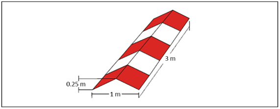
Figure GM1-F-1. Runway-type FATO edge marker
CS HPT-DSN.F.540 Final approach and take-off area designation marking
ED Decision 2019/012/R
(a) Applicability: A FATO designation marking should be provided on a runway-type FATO at a heliport where it is necessary to designate the FATO to the pilot.
(b) Location: Where provided, a FATO designation marking should be located at the beginning of the runway-type FATO (see Figure F-2).
(c) Characteristics: A FATO designation marking should consist of a two-digit number. The two-digit number should be the whole number nearest the one-tenth of the magnetic North when viewed from the direction of approach. When the above rule would give a single digit number, it should be preceded by a zero (see Figure F-2).
GM1 HPT-DSN.F.540 Final approach and take-off area designation marking
ED Decision 2019/012/R
For a runway-type FATO, the numbers and the letter of the marking should have a white colour and should be in the form and proportion shown in Figure GM1-F-2.
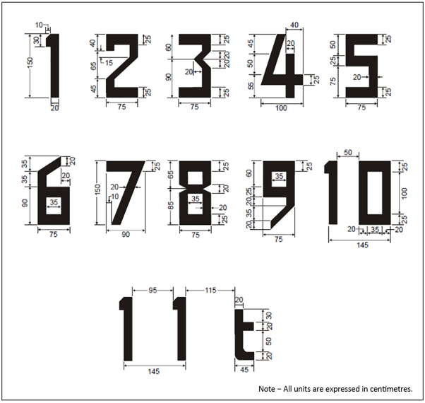
Figure GM1-F-2. Form and proportions of numbers and letter
CS HPT-DSN.F.550 Aiming point marking
ED Decision 2019/012/R
(a) The safety objective of an aiming point marking is to provide a visual cue indicating to the pilot the preferred approach/departure direction, to the point to which the helicopter approaches to hover before positioning to a stand where a touchdown should be made, and that the surface of the FATO is not intended for touchdown.
(b) Location: Where provided, the aiming point marking should be located within the FATO (see Figure F-1).
(c) Characteristics:
(i) The aiming point marking should be an equilateral triangle with a minimum side length of 9.0 metres, with the bisector of one of the angles aligned with the preferred approach direction.
(ii) The marking should consist of continuous white lines, 1.0 m in width (see Figures F-1 and F-12).
GM1 HPT-DSN.F.550 Aiming point marking
ED Decision 2019/012/R
For all FATOs except runway-type FATOs, the aiming point marking should be located at the centre of the FATO, as shown in Figure F-1.
CS HPT-DSN.F.560 Touchdown and lift-off area perimeter marking
ED Decision 2019/012/R
(a) The safety objective of the touchdown and lift-off area perimeter marking is to provide to the pilot a clear indication of a TLOF.
(b) Applicability: When the perimeter of the TLOF is not self-evident, a TLOF perimeter marking should be displayed on a TLOF located in a FATO.
(c) Location: Where provided, the TLOF perimeter marking should be located along the edge of the TLOF.
(d) Characteristics: A TLOF perimeter marking should consist of a continuous white line with a width of at least 30 cm.
GM1 HPT-DSN.F.560 Touchdown and lift-off area perimeter marking
ED Decision 2019/012/R
A TLOF perimeter marking should be provided on each TLOF collocated with a helicopter stand.
CS HPT-DSN.F.570 Touchdown/positioning marking
ED Decision 2019/012/R
(a) Applicability:
(1) A touchdown/positioning marking should be provided where it is necessary for a helicopter to touch down and/or be accurately positioned.
(2) A touchdown/positioning marking should be provided on a helicopter stand designed for turning.
(b) Location:
(1) A touchdown/positioning marking should be located so that when the pilot’s seat is over the marking, the whole of the undercarriage should be within the TLOF and all parts of the helicopter should be clear of any obstacle by a safe margin.
(2) On a heliport, the centre of the touchdown/positioning marking should be located at the centre of the TLOF, except the centre of the touchdown/positioning marking may be offset away from the centre of the TLOF where a safety assessment indicates such offsetting to be necessary, and providing that a marking that is so offset would not adversely affect safety.
(3) For a helicopter stand designed for hover turning, the touchdown/positioning marking should be located in the centre of the central zone (see Figure D-1).
(c) Characteristics:
(1) A touchdown/positioning marking should be a yellow circle and have a line width of at least 0.5 m.
(2) The inner diameter of the touchdown/positioning marking should be 0.5 D of the largest helicopter the TLOF and/or the helicopter stand is intended to serve.
CS HPT-DSN.F.580 Heliport name marking
ED Decision 2019/012/R
(a) Applicability: A heliport name marking should be provided at a heliport where there is insufficient alternative means of visual identification.
(b) Characteristics: A heliport name marking should consist of the name or the alphanumeric designator of the heliport as used in radio (R/T) communications.
GM1 HPT-DSN.F.580 Heliport name marking
ED Decision 2019/012/R
(a) Location: The heliport name marking should be displayed on the heliport so as to be visible, as far as practicable, at all angles above the horizontal.
(b) Characteristics:
(1) A heliport name marking intended for use at night or during conditions of poor visibility should be illuminated, either internally or externally.
(2) The colour of the marking should contrast with the background and preferably be white.
(3) Runway-type FATOs: The characters of the marking should be not less than 3 m in height.
(4) All FATOs except runway-type FATOs: The characters of the marking should be not less than 1.5 m in height.
CS HPT-DSN.F.590 Helicopter ground taxiway markings and markers
ED Decision 2019/012/R
(a) Applicability:
(1) The specifications for runway-holding position markings defined in CS ADR-DSN.L.575 and for intermediate holding position marking defined in CS ADR-DSN.L.580 are equally applicable to taxiways intended for ground taxiing of helicopters.
(2) The centre line of a helicopter ground taxiway should be identified with a marking.
(3) The edges of a helicopter ground taxiway, if not self-evident, should be identified with markers or markings.
(b) Location:
(1) Helicopter ground taxiway markings should be along the centre line, and, if provided, along the edges of a helicopter ground taxiway.
(2) Helicopter ground taxiway edge markers should be located at a distance of 0.5 m to 3 m beyond the edge of the helicopter ground taxiway.
(3) Where provided, helicopter ground taxiway edge markers should be spaced at intervals of not more than 15 m on each side of straight sections and 7.5 m on each side of curved sections with a minimum of four equally spaced markers per section.
(c) Characteristics:
(1) A helicopter ground taxiway centre line marking should be a continuous yellow line 15 cm in width.
(2) Helicopter ground taxiway edge markings should be a continuous double yellow line, each 15 cm in width, and spaced 15 cm apart (nearest edge to nearest edge).
(3) A helicopter ground taxiway edge marker should not exceed the height of a plane originating at a height of 25 cm above the plane of the helicopter ground taxiway, at a distance of 0.5 m from the edge of the helicopter ground taxiway and sloping upwards and outwards at a gradient of 5 per cent to a distance of 3 m beyond the edge of the helicopter ground taxiway.
(4) Helicopter ground taxiway edge markers should be frangible to the wheeled undercarriage of helicopters.
(5) A helicopter ground taxiway edge marker should be blue.
(6) If the helicopter ground taxiway is to be used at night, the edge markers should be internally illuminated or retro-reflective.
GM1 HPT-DSN.F.590 Helicopter ground taxiway markings and markers
ED Decision 2019/012/R
(a) Ground taxi-routes are not required to be marked.
(b) Where necessary, signage should be provided on an aerodrome to indicate that a ground taxiway is suitable only for the use of helicopters.
(c) A helicopter ground taxiway edge marker should not present a hazard for aircraft operations.
CS HPT-DSN.F.600 Helicopter air taxiway markings and markers
ED Decision 2019/012/R
(a) Applicability:
(1) The specifications for runway-holding position markings defined in CS ADR-DSN.L.575 and intermediate holding position marking defined in CS ADR-DSN.L.580 are equally applicable to taxiways intended for air taxiing of helicopters.
(2) The centre line of a helicopter air taxiway or, if not self-evident, the edges of a helicopter air taxiway, should be identified with markers or markings.
(b) Location:
(1) A helicopter air taxiway centre line marking or flush in-ground centre line marker should be located along the centre line of the helicopter air taxiway.
(2) Helicopter air taxiway edge markings should be located along the edges of a helicopter air taxiway.
(3) Helicopter air taxiway edge markers should be located at a distance of 1 m to 3 m beyond the edge of the helicopter air taxiway.
(c) Characteristics:
(1) A helicopter air taxiway centre line should be marked with a continuous yellow line 15 cm in width, when on a paved surface.
(2) The edges of a helicopter air taxiway, when on a paved surface, should be marked with continuous double yellow lines each 15 cm in width, and spaced 15 cm apart (nearest edge to nearest edge).
(3) Where a helicopter air taxiway is located on an unpaved surface and painted markings of a helicopter air taxiway centre line cannot be provided, it should be marked with flush in-ground 15 cm wide and approximately 1.5 m in length yellow markers, spaced at intervals of not more than 30 m on straight sections and not more than 15 m on curves, with a minimum of four equally spaced markers per section.
(4) Helicopter air taxiway edge markers, where provided, should be spaced at intervals of not more than 30 m on each side of straight sections and not more than 15 m on each side of curves, with a minimum of four equally spaced markers per section.
(5) Helicopter air taxiway edge markers should be frangible.
(6) Helicopter air taxiway edge markers should not penetrate a plane originating at a height of 25 cm above the plane of the helicopter air taxiway, at a distance of 1 m from the edge of the helicopter air taxiway and sloping upwards and outwards at a gradient of 5 per cent to a distance of 3 m beyond the edge of the helicopter air taxiway.
(7) A helicopter air taxiway edge marker should be of a colour (or colours) that contrasts (contrast) effectively against the operating background. The red colour should not be used for markers.
(8) If the helicopter air taxiway is to be used at night, helicopter air taxiway edge markers should be either internally illuminated or retro-reflective.
GM1 HPT-DSN.F.600 Helicopter air taxiway markings and markers
ED Decision 2019/012/R
(a) Helicopter air taxi-routes are not required to be marked.
(b) Where a helicopter air taxiway could be confused with a helicopter ground taxiway, signage should be provided to indicate the mode of taxi operations that are permitted.
(c) Helicopter air taxiway edge markers should not be located at a distance from the centre line of the helicopter air taxiway of less than 0.5 times the largest overall width of the helicopter for which it is designed.
(d) Helicopter air taxiway edge markers should not penetrate a plane originating at a height of 25 cm above the plane of the helicopter air taxiway, at a distance from the centre line of the helicopter air taxiway of 0.5 times the largest overall width of the helicopter for which it is designed, and sloping upwards and outwards at a gradient of 5 per cent.
CS HPT-DSN.F.610 Helicopter stand markings
ED Decision 2019/012/R
(a) Applicability:
(1) A helicopter stand perimeter marking should be provided on a helicopter stand designed for turning. If a helicopter stand perimeter marking is not practicable, a central zone perimeter marking should be provided instead if the perimeter of the central zone is not self-evident.
(2) For a helicopter stand that is intended to be used for taxi-through and which does not allow a helicopter to turn, a stop line should be provided.
(3) Alignment lines and lead-in/lead-out lines should be provided on a helicopter stand (see Figures F-4 and F-5).
(b) Location:
(1) A helicopter stand perimeter marking on a helicopter stand designed for turning or, a central zone perimeter marking, should be concentric with the central zone of the stand.
(2) For a helicopter stand that is intended to be used for taxi-through and which does not allow the helicopter to turn, a stop line should be located on the helicopter ground taxiway axis at right angles to the centre line.
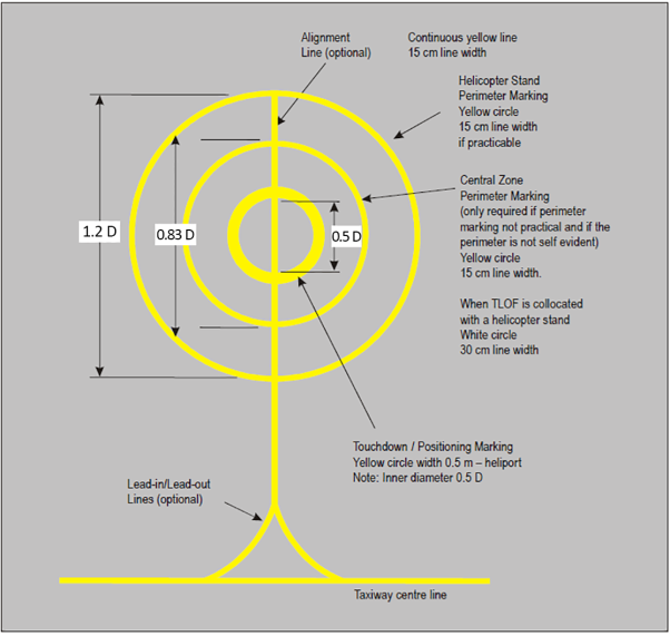
Figure F-4. Helicopter stand markings at a stand designated for hover turning
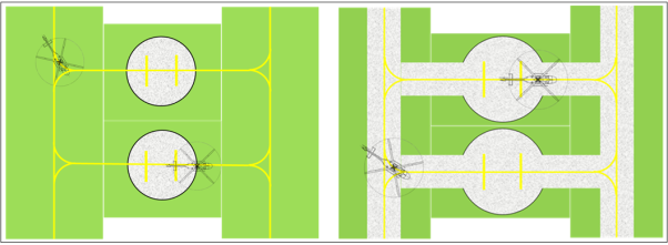
Figure F-5. Taxi through helicopter stand markings
(c) Characteristics:
(1) A helicopter stand perimeter marking should be a yellow circle and have a line width of 15 cm.
(2) A central zone perimeter marking should be a yellow circle and have a line width of 15 cm, except when the TLOF is collocated with a helicopter stand, in which case the characteristics of the TLOF perimeter markings should apply.
(3) For a helicopter stand that is intended to be used for taxi-through and which does not allow the helicopter to turn, the yellow stop line should not be less than the width of the helicopter ground taxiway and should have a line thickness of 50 cm.
(4) Alignment lines and lead-in/lead-out lines should be continuous yellow lines and should have a width of 15 cm.
(5) Curved portions of alignment lines and lead-in/lead-out lines should have radii appropriate to the most demanding helicopter type the helicopter stand is intended to serve.
(6) Stand identification markings should be marked in a contrasting colour so as to be easily readable.
(7) Where it is intended that helicopters proceed in one direction only, arrows indicating the direction to be followed may be added as part of the alignment lines.
GM1 HPT-DSN.F.610 Helicopter stand markings
ED Decision 2019/012/R
Helicopter stand identification markings should be provided where there is a need to identify individual stands.
CS HPT-DSN.F.620 Flight path alignment guidance marking
ED Decision 2019/012/R
(a) Applicability: Where provided at a heliport, a flight path alignment guidance marking (or markings) should indicate the available approach and/or departure path direction(s).
(b) Location: The flight path alignment guidance marking should be located in a straight line along the direction of approach and/or departure path on one or more of the TLOF, FATO, safety area or any suitable surface in the immediate vicinity of the FATO or the safety area.
(c) Characteristics:
(1) A flight path alignment guidance marking should consist of one or more arrows marked on the TLOF, FATO and/or safety area surface, as shown in Figure F-6. The stroke of the arrow(s) should be 50 cm in width and at least 3 m in length. When combined with a flight path alignment guidance lighting system, it should take the form shown in Figure F-6, which includes the scheme for marking the ‘heads of the arrows’, which are always of the same size, regardless of the stroke length.
(2) In the case of a flight path limited to a single approach direction or a single departure direction, the arrow marking may be unidirectional. In the case of a heliport with only a single approach/departure path available, one bidirectional arrow is marked.
(3) The markings should be in a colour, preferably white, which provides good contrast against the background colour of the surface on which they are marked.
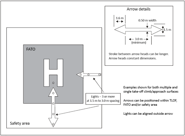
Figure F-6. Flight path alignment guidance markings and lights
GM1 HPT-DSN.F.620 Flight path alignment guidance marking
ED Decision 2019/012/R
Intentionally left blank
CS HPT-DSN.F.630 Approach lighting system
ED Decision 2019/012/R
(a) Applicability: Where provided at a heliport, an approach lighting system should indicate a preferred approach direction.
(b) Location: The approach lighting system should be located in a straight line along the preferred direction of approach.
(c) Characteristics:
(1) An approach lighting system should consist of a row of three lights spaced uniformly at 30 m intervals and of a crossbar 18 m in length at a distance of 90 m from the perimeter of the FATO as shown in Figure F-7. The lights forming the crossbar should be as nearly as practicable in a horizontal straight line at right angles to, and bisected by, the line of the centre line lights, and spaced at 4.5 m intervals.
(2) Where there is a need to make the final approach course more conspicuous, additional lights spaced uniformly at 30 m intervals should be added beyond the crossbar. The lights beyond the crossbar may be steady or sequenced flashing, depending upon the environment.
(3) The steady lights should be omnidirectional white lights.
(4) Sequenced flashing lights should be omnidirectional white lights.
(5) The flashing lights should have a flash frequency of one per second and their light distribution should be as shown in Figure F-9, Illustration 2. The flash sequence should commence from the outermost light and progress towards the crossbar.
(6) A suitable brilliancy control should be incorporated to allow for adjustment of light intensity to meet the prevailing conditions.
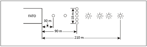
Figure F-7. Approach lighting system
GM1 HPT-DSN.F.630 Approach lighting system
ED Decision 2019/012/R
Additional guidance on light intensity controls is given in GM1 ADR-DSN.M.615.
CS HPT-DSN.F.640 Flight path alignment guidance lighting system
ED Decision 2019/012/R
(a) Applicability: Where provided at a heliport, a flight path alignment guidance lighting system (or systems) should indicate the available approach and/or departure path direction(s).
(b) Location:
(1) The flight path alignment guidance lighting system should be in a straight line along the direction(s) of approach and/or departure path on one or more of the TLOF, FATO, safety area or any suitable surface in the immediate vicinity of the FATO, TLOF or safety area.
(2) If combined with a flight path alignment guidance marking, then as far as is practicable, the lights should be located inside the ‘arrow’ markings.
(c) Characteristics:
(1) A flight path alignment guidance lighting system should consist of a row of three or more lights spaced uniformly over a total minimum distance of 6 m. Intervals between lights should not be less than 1.5 m and should not exceed 3 m.
(2) Where space permits, there should be 5 lights. The number of lights and the spacing between these lights may be adjusted to reflect the space available.
(3) If more than one flight path alignment system is used to indicate the available approach and/or departure path direction(s), the characteristics for each system are typically kept the same (see Figure F-6).
(4) The lights should be steady omnidirectional inset white lights.
(5) The distribution of the lights should be as indicated in Figure F-9, Illustration 5.
(6) A suitable control should be incorporated to allow for adjustment of light intensity to meet the prevailing conditions and to balance the flight path alignment guidance lighting system with other heliport lights and general lighting that may be present around the heliport.
GM1 HPT-DSN.F.640 Flight path alignment guidance lighting system
ED Decision 2019/012/R
The flight path alignment guidance lighting can be combined with a flight path alignment guidance marking (or markings).
CS HPT-DSN.F.650 Visual alignment guidance system
ED Decision 2019/012/R
(a) Applicability: Where provided at a heliport, a visual alignment guidance system should provide guidance to the pilot during the approach to a heliport.
(b) Location:
(1) The visual alignment guidance system should be located such that a helicopter is guided along the prescribed track towards the FATO.
(2) The system should be located at the downwind edge of the FATO and aligned along the preferred approach direction.
(3) The light units should be frangible and mounted as low as possible.
(4) Where the lights of the system need to be seen as discrete sources, light units should be located such that at the extremes of system coverage, the angle subtended between the units as seen by the pilot should not be less than 3 minutes of arc.
(5) The angles subtended between the light units of the system and other units of comparable or greater intensities should also be not less than 3 minutes of arc.
(6) The requirements of paragraphs (4) and (5) above can be met for lights on a line normal to the line of sight if the light units are separated by 1 m for every kilometre of viewing range.
(c) Signal format:
(1) The signal format of the alignment guidance system should include a minimum of three discrete signal sectors providing ‘offset to the right’, ‘on track’ and ‘offset to the left’ signals.
(2) The divergence of the ‘on track’ sector of the system should be 1° as shown in Figure F-8.
(3) The signal format should be such that there is no possibility of confusion between the system and any associated visual approach slope indicator or other visual aids.
(4) The system should avoid the use of the same coding as any associated visual approach slope indicator.
(5) The signal format should be such that the system is unique and conspicuous in all operational environments.
(6) The system should not significantly increase the pilot workload.
(d) Light distribution:
(1) The usable coverage of the visual alignment guidance system should be equal to or better than that of the visual approach slope indicator system with which it is associated.
(2) A suitable intensity control should be provided so as to allow adjustment to meet the prevailing conditions and to avoid dazzling the pilot during approach and landing.
(e) Approach track and azimuth setting:
(1) A visual alignment guidance system should be capable of adjustment in azimuth to within ± 5 minutes of arc of the desired approach path.
(2) The angle of the azimuth guidance system should be such that during an approach, the pilot of a helicopter at the boundary of the ‘on track’ signal would clear all objects in the approach area by a safe margin.
(3) The characteristics of the obstacle protection surface specified in
CS HPT-DSN.F.660(h)(2), Table F-1 and Figure F-10 should equally apply to the system.
(f) Characteristics of the visual alignment guidance system:
(1) In the event of a failure of any component affecting the signal format, the system should be automatically switched off.
(2) The light units should be so designed that deposits of condensation, ice, dirt, etc. on optically transmitting or reflecting surfaces would interfere to the least possible extent with the light signal and should not cause spurious or false signals to be generated.
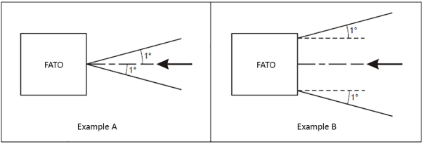
Figure F-8. Divergence of the ‘on track’ sector
|
Illustration 1 − Approach light steady burning |
Illustration 2 − Approach light flashing |
|
Illustration 3 − HAPI system |
Illustration 4 − Final approach and take-off lights and aiming point lights |
|
Note − Additional values may be required in the case of installations requiring identification by means of the lights at an elevation of less than two degrees. Illustration 5 − TLOF perimeter lights and flight path alignment guidance lighting system |
Illustration 6 − Touchdown and lift-off area luminescent panels |
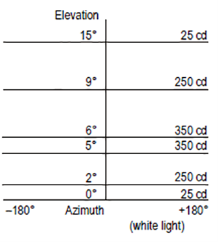
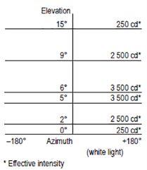
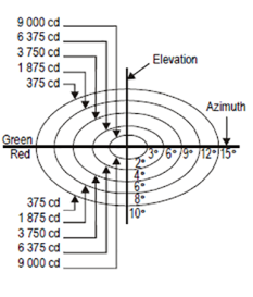
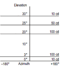
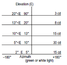
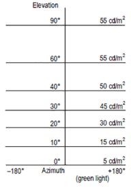
Figure F-9. Isocandela diagrams
|
SURFACE AND DIMENSIONS |
FATO |
|
|
Length of inner edge |
Width of safety area |
|
|
Distance from end of FATO |
3 m minimum |
|
|
Divergence |
10 % |
|
|
Total length |
2 500 m |
|
|
Slope |
PAPI |
Aa – 0.57° |
|
|
HAPI |
Ab – 0.65° |
|
|
APAPI |
Aa – 0.9° |
|
a. As indicated in CS ADR-DSN.M.645, Figure M-4. b. The angle of the upper boundary of the ‘below slope’ signal. |
||
Table F-1. Dimensions and slopes of the obstacle protection surface for heliport visual approach indicator system
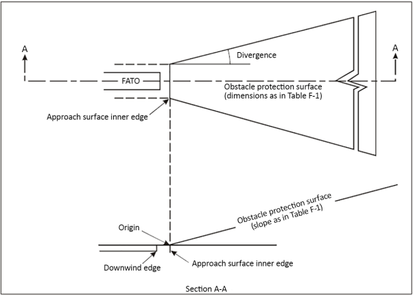
Figure F-10. Obstacle protection surface for visual approach slope indicator systems
GM1 HPT-DSN.F.650 Visual alignment guidance system
ED Decision 2019/012/R
A visual alignment guidance system should be provided where one or more of the following conditions exist:
(a) obstacle clearance, noise abatement or traffic control procedures require a particular direction to be flown;
(b) the environment of the heliport provides few visual surface cues; and
(c) it is physically impracticable to install an approach lighting system.
CS HPT-DSN.F.660 Visual approach slope indicator
ED Decision 2019/012/R
(a) Applicability: Where provided at a heliport, a visual slope indicator system should provide information on the approach angle necessary to maintain a safe height over obstacles on the approach to a heliport.
(b) The standard visual approach slope indicator systems for helicopter operations should consist of the following:
(1) PAPI (precision approach path indicator) and APAPI (abbreviated precision approach path indicator) systems conforming to the specifications contained in CS ADR-DSN.M.645 and CS ADR-DSN.M.650, except that the angular size of the on-slope sector of the systems should be increased to 45 minutes of arc; or
(2) HAPI (helicopter approach path indicator) system conforming to the specifications in paragraphs (d) to (g) below.
(c) Location:
(1) A visual approach slope indicator should be located such that a helicopter is guided to the desired position within the FATO and so as to avoid dazzling the pilot during final approach and landing.
(2) The light unit(s) should be mounted as low as possible.
(d) Characteristics of the HAPI signal format:
(1) The signal format of the HAPI should include four discrete signal sectors, providing an ‘above slope’, an ‘on slope’, a ‘slightly below’ and a ‘below slope’ signal.
(2) The signal format of the HAPI should be as shown in Figure F-11, Illustrations A and B.
(3) The signal repetition rate of the flashing sector of the HAPI should be at least 2 Hz.
(4) The on-to-off ratio of pulsing signals of the HAPI should be 1 to 1, and the modulation depth should be at least 80 per cent.
(5) The angular size of the ‘on-slope’ sector of the HAPI should be 45 minutes of arc.
(6) The angular size of the ‘slightly below’ sector of the HAPI should be 15 minutes of arc.
|
|
|
|
|
|
|
|
Sector |
Format |
|
|
|
|
Above |
Flashing green |
|
|
|
|
On slope |
Green |
|
|
|
|
Slightly below |
Red |
|
|
|
|
Below |
Flashing red |
|
|
|
|
|
|||
|
|
Illustration A |
|
Illustration B |
|
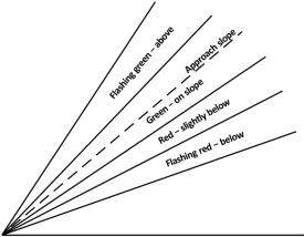
Figure F-11. HAPI signal format
(e) Light distribution:
(1) The light intensity distribution of the HAPI in red and green colours should be as shown in Figure F-9, Illustration 3.
(2) The colour transition of the HAPI in the vertical plane should be such as to appear to an observer at a distance of not less than 300 m to occur within a vertical angle of not more than three minutes of arc.
(3) The transmission factor of a red or green filter should be not less than 15 per cent at the maximum intensity setting.
(4) At full intensity, the red light of the HAPI should have a Y-coordinate not exceeding 0.320, and the green light should be within the boundaries specified in CS ADR-DSN.U.930(b).
(5) A suitable intensity control should be provided so as to allow adjustment to meet the prevailing conditions and to avoid dazzling the pilot during approach and landing.
(f) Approach slope and elevation setting:
(1) A HAPI system should be capable of adjustment in elevation at any desired angle between 1 degree and 12 degrees above the horizontal with an accuracy of ± 5 minutes of arc.
(2) The angle of elevation setting of a HAPI should be such that during an approach, the pilot of a helicopter observing the upper boundary of the ‘below slope’ signal would clear all objects in the approach area by a safe margin.
(g) Characteristics of the light unit:
(1) The system should be so designed that:
(i) in the event the vertical misalignment of a unit exceeds ± 0.5 degrees (± 30 minutes), the system should switch off automatically; and
(ii) if the flashing mechanism fails, no light is emitted in the failed flashing sector(s).
(2) The light unit of the HAPI should be so designed that deposits of condensation, ice, dirt, etc. on optically transmitting or reflecting surfaces would interfere to the least possible extent with the light signal and should not cause spurious or false signals to be generated.
(h) Obstacle protection surface (applicable to PAPI, APAPI and HAPI):
(1) An obstacle protection surface should be established when it is intended to provide a visual approach slope indicator system.
(2) The characteristics of the obstacle protection surface, i.e. origin, divergence, length and slope, should correspond to those specified in the relevant column of Table F-1 and in Figure F-10.
(3) New objects or extensions of existing objects should not be permitted above an obstacle protection surface except when the new object or extension would be shielded by an existing immovable object.
(4) Existing objects above an obstacle protection surface should be removed except when the object is shielded by an existing immovable object, or when after a safety assessment, it is determined that the object would not adversely affect the safety of operations of helicopters.
(5) Where a safety assessment indicates that an existing object extending above an obstacle protection surface could adversely affect the safety of operations of helicopters, one or more of the following measures should be taken:
(i) suitably raise the approach slope of the system;
(ii) reduce the azimuth spread of the system so that the object is outside the confines of the beam;
(iii) displace the axis of the system and its associated obstacle protection surface by no more than 5 degrees;
(iv) suitably displace the FATO; and
(v) install a visual alignment guidance system.
GM1 HPT-DSN.F.660 Visual approach slope indicator
ED Decision 2019/012/R
(a) A visual approach slope indicator should be provided for a heliport where one or more of the following conditions exist:
(1) obstacle clearance, noise abatement or traffic control procedures require a particular slope to be flown;
(2) the environment of the heliport provides few visual surface cues; and
(3) the characteristics of the helicopter require a stabilised approach.
(b) When more than one visual approach slope indicator is installed at an aerodrome (e.g. PAPI, APAPI), a visual approach slope indicator should be designed and calibrated in order to give a clear and unambiguous indication to helicopter pilots approaching to land.
(c) A heliport visual approach slope indicator should be located adjacent to the nominal aiming point and aligned in azimuth with the preferred approach direction.
(d) Care is required in the design of the unit to minimise spurious signals between the signal sectors, and at the azimuth coverage limits.
(e) Larger azimuth coverage can be obtained by installing the HAPI system on a turntable.
CS HPT-DSN.F.670 Final approach and take-off area lighting systems
ED Decision 2019/012/R
(a) Applicability: FATO lights should be provided where a FATO is established at a heliport intended for use at night. They can be omitted where the FATO and the TLOF are nearly coincidental and the TLOF lights are provided, or the extent of the FATO is self-evident.
(b) Location: FATO lights should be placed along the edges of the FATO. The lights should be uniformly spaced as follows:
(1) for an area in the form of a square or rectangle, at intervals of not more than 50 m with a minimum of four lights on each side including a light at each corner; and
(2) for any other shaped area, including a circular area, at intervals of not more than 5 m with a minimum of ten lights.
(c) Characteristics:
(1) FATO lights should be fixed omnidirectional lights showing white. Where the intensity of the lights is to be varied, the lights should show variable white.
(2) The light distribution of FATO lights should be as shown in Figure F-9, Illustration 4.
(3) The lights should not exceed a height of 25 cm and should be inset when a light extending above the surface would endanger helicopter operations.
(4) Where a FATO is not meant for lift-off or touchdown, the lights should not exceed a height of 25 cm above ground or snow level.
GM1 HPT-DSN.F.670 Final approach and take-off area lighting systems
ED Decision 2019/012/R
Intentionally left blank
CS HPT-DSN.F.680 Aiming point lights
ED Decision 2019/012/R
(a) Applicability: Aiming point lights should be provided where an aiming point marking is provided at a heliport intended for use at night.
(b) Location: Aiming point lights should be collocated with the aiming point marking.
(c) Characteristics:
(1) Aiming point lights should form a pattern of at least six omnidirectional white lights (see Figure F-12).
(2) The lights should be inset when a light extending above the surface could endanger helicopter operations.
(3) The light distribution of aiming point lights should be as shown in Figure F-9, Illustration 4.
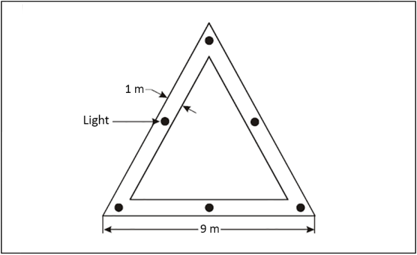
Figure F-12. Aiming point marking and lighting
CS HPT-DSN.F.690 Touchdown and lift-off area lighting system
ED Decision 2019/012/R
(a) Applicability:
(1) A TLOF lighting system should be provided at a heliport intended for use at night.
(2) The TLOF lighting system for a heliport should consist of one or more of the following:
(i) perimeter lights; or
(ii) floodlighting; or
(iii) ASPSL or LP lighting to identify the TLOF when (i) and (ii) are not practicable and FATO lights are available.
(b) Location:
(1) TLOF perimeter lights should be placed along the edge of the area designated for use as the TLOF or within a distance of 1.5 m from the edge.
(2) Where the TLOF is a circle, the lights should be:
(i) located on straight lines in a pattern which should provide information to pilots on drift displacement; or
(ii) evenly spaced around the perimeter of the TLOF at the appropriate intervals, sufficient to present the pattern, except that over a sector of 45 degrees, the lights should be spaced at half spacing.
(3) TLOF perimeter lights should be uniformly spaced at intervals of not more than 5 m.
(4) Where TLOF perimeter lights are located on straight lines, there should be a minimum number of four lights on each side, including a light at each corner.
(5) For a circular TLOF, where lights are installed in accordance with paragraph (2)(ii) above, there should be a minimum of fourteen lights.
(6) Where ASPSL or LPs are provided to identify the TLOF, which is not a circle, they should be placed along the marking designating the edge of the TLOF.
(7) Where ASPL or LPs are provided to identify the TLOF, which is a circle, they should be located on straight lines circumscribing the area.
(8) The minimum number of LPs on a TLOF should be nine.
(9) The total length of LPs in a pattern should not be less than 50 per cent of the length of the pattern.
(10) There should be an odd number of LPs with a minimum number of three panels on each side of the TLOF, including a panel at each corner.
(11) LPs should be uniformly spaced with a distance between adjacent panel ends of not more than 5 m on each side of the TLOF.
(12) TLOF floodlights should be located so as to avoid glare to pilots in flight or to personnel working on the area.
(13) The arrangement and aiming of floodlights should be such that shadows are kept to a minimum.
(c) Characteristics:
(1) The TLOF perimeter lights should be fixed omnidirectional lights showing green.
(2) ASPSL or LPs should emit green light when used to define the perimeter of the TLOF.
(3) The chromaticity and luminance of colours of LPs should be in accordance with the specifications in CS ADR-DSN.U.935.
(4) An LP should have a minimum width of 6 cm. The panel housing should be the same colour as the marking it defines.
(5) The perimeter lights should not exceed a height of 25 cm and should be inset when a light extending above the surface could endanger helicopter operations.
(6) When located within the safety area of a heliport, the TLOF floodlights should not exceed a height of 25 cm.
(7) The LPs should not extend above the surface by more than 2.5 cm.
(8) The light distribution of the perimeter lights should be as shown in Figure F-9, Illustration 5.
(9) The light distribution of the LPs should be as shown in Figure F-9, Illustration 6.
(10) The spectral distribution of TLOF area floodlights should be such that the surface and obstacle marking can be correctly identified.
(11) The average horizontal illuminance of the floodlighting should be at least 10 lux, with a uniformity ratio (average to minimum) of not more than 8:1 measured on the surface of the TLOF.
(12) The lighting used to identify the touchdown marking should comprise a segmented circle of omnidirectional ASPSL strips showing yellow. The segments should consist of ASPSL strips, and the total length of the ASPSL strips should not be less than 50 per cent of the circumference of the circle.
(13) If utilised, the heliport identification marking lighting should be omnidirectional showing green.
GM1 HPT-DSN.F.690 Touchdown and lift-off area lighting system
ED Decision 2019/012/R
TLOF ASPSL and/or LPs to identify the touchdown marking and/or floodlighting should be provided for use at night when enhanced surface texture cues are required.
CS HPT-DSN.F.700 Taxiway lights
ED Decision 2019/012/R
The specifications of CS ADR-DSN.M.710, CS ADR-DSN.M.715 and CS ADR-DSN.M.720 are applicable to taxiways intended for ground taxiing of helicopters.
CS HPT-DSN.F.710 Visual aids for denoting obstacles
ED Decision 2019/012/R
Obstacles should be marked and lit in accordance with CS ADR-DSN.Q.840, CS ADR-DSN.Q.845 and CS ADR-DSN.Q.850.
GM1 HPT-DSN.F.710 Visual aids for denoting obstacles
ED Decision 2019/012/R
(a) General: If it is not possible to display obstacle lights on obstacles at a heliport intended for use at night, the obstacles should be floodlit.
(b) Location: Obstacle floodlights should be arranged so as to illuminate the entire obstacle and, as far as practicable, in a manner so as not to dazzle helicopter pilots.
(c) Characteristics: Obstacle floodlighting should produce a luminance of at least 10 cd/m2.