CS ADR-DSN.K.490 Wind direction indicator
ED Decision 2014/013/R
(a) An aerodrome should be equipped with a sufficient number of wind direction indicators in order to provide wind information to the pilot during approach and take-off.
(b) Location:
Each wind direction indicator should be located so that at least one wind direction indicator is visible from aircraft in flight, during approach or on the movement area before take-off, and in such a way as to be free from the effects of air disturbances caused by nearby objects.
(c) Characteristics:
(1) Each wind direction indicator should be in the form of a truncated cone made of fabric and should have a length of not less than 3.6 m and a diameter, at the larger end, of not less than 0.9 m.
(2) It should be constructed so that it gives a clear indication of the direction of the surface wind and a general indication of the wind speed.
(3) The colour or colours should be so selected as to make the wind direction indicator clearly visible and understandable from a height of at least 300 m. Having regard to background:
(i) where practicable, a single colour should be used; and
(ii) where a combination of two colours is required to give adequate conspicuity against changing backgrounds, they should preferably be orange and white, red and white, or black and white, and should be arranged in five alternate bands, the first and last bands being the darker colour.
(d) Night conditions:
Provision should be made for illuminating a sufficient number of wind indicators at an aerodrome intended for use at night.
GM1 ADR-DSN.K.490 Wind direction indicator
ED Decision 2016/027/R
(a) Wind direction indicators are important visual aids for all runway ends. Large wind direction indicators are particularly important at aerodromes where landing information is not available through radio communications. On the other hand, landing direction indicators are seldom used due to the necessity and, consequently, responsibility, of changing their direction as wind direction shifts. Visual ground signals for runway and taxiway serviceability are contained in ICAO Annex 2. Additional guidance is given in ICAO Doc 9157, Aerodrome Design Manual, Part 4, Visual Aids, Chapter 3.
(b) A fabric wind cone is generally the type preferred by pilots because it provides a general indication of wind speed. Cones that extend fully at wind speeds of about 15 kt are most useful since this is the maximum crosswind landing component for small aircraft.
(c) It may be possible to improve the perception by the pilot of the location of the wind direction indicator by several means notably by circular marking around this indicator. The location of at least one wind direction indicator should be marked by a circular band 15 m in diameter and 1.2 m wide. The band should be centred about the wind direction indicator support, and should be in a colour chosen to give adequate conspicuity, preferably white.
(d) The usefulness of any visual aid is determined largely by its size, conspicuity, and location. Given conditions of good atmospheric visibility, the maximum distance at which the information available from an illuminated wind sleeve can be usefully interpreted is 1 km. Thus, in order that a pilot may make use of this information whilst on approach, the wind sleeve should be sited no farther from the runway threshold than 600 m. Obstacle criteria excluded, the ideal location is 300 m along the runway from the threshold and laterally displaced at 80 m from the runway centre line.
(e) This means, in effect, that only those aerodromes where the thresholds are less than 1 200 m apart can meet the minimum requirement with a single unit. Most code 3 and 4 aerodromes should require two or more units suitably sited in order to provide the best possible coverage.
(f) The final choice of unit numbers and location should depend on a number of factors which should vary from aerodrome to aerodrome. However, when deciding on the most appropriate location, account should be taken to ensure that the wind direction indicator is:
(1) outside the Cleared and Graded Area of the runway and taxiway strips;
(2) clear of the OFZ and ILS critical/sensitive areas where appropriate;
(3) preferably not more than 200 m lateral displacement from the runway edge;
(4) preferably between 300 m and 600 m from the runway threshold measured along the runway;
(5) in an area with low background levels of illumination;
(6) visible from the approach and take-off positions of all runways; and
(7) free from the effects of air disturbance caused by nearby objects.
[Issue: ADR-DSN/3]
CS ADR-DSN.K.495 Landing direction indicator
ED Decision 2014/013/R
(a) Location: Where provided, a landing direction indicator should be located in a conspicuous place on the aerodrome.
(b) Characteristics:
(1) The landing direction indicator should be in the form of a ‘T’.
(2) The shape and minimum dimensions of a landing ‘T’ should be as shown in Figure K-1.
(3) The colour of the landing ‘T’ should be either white or orange, the choice being dependent on the colour that contrasts best with the background against which the indicator should be viewed.
(4) Where used at night, the landing ‘T’ should either be illuminated or outlined by white lights.
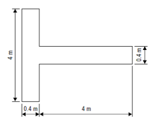
Figure K-1. Landing direction indicator
GM1 ADR-DSN.K.495 Landing direction indicator
ED Decision 2014/013/R
The landing ‘T’ may be constructed of wood or other light material and its dimensions may correspond to those shown in Figure K-1. It may be painted white or orange. The landing ‘T’ should be mounted on a cement concrete pedestal adequately reinforced with steel bars to avoid cracks resulting from unequal settlement. The surface of the pedestal should be finished smooth with a steel trowel and coated with paint of appropriate colour. The colour of the pedestal should be chosen to contrast with the colour of the landing ‘T’. Before fastening the landing ‘T’ base to the concrete pedestal, the mounting bolts should be checked for correct spacing. The landing ‘T’ should be assembled and mounted in accordance with the manufacturer’s installation instructions. It should be free to move about a vertical axis so that it can be set in any direction. Where required for use at night, the landing ‘T’ should either be illuminated or outlined by white lights.
CS ADR-DSN.K.500 Signalling lamp
ED Decision 2014/013/R
(a) A signalling lamp should be provided at a controlled aerodrome in the aerodrome control tower.
(b) Characteristics:
(1) A signalling lamp should be capable of producing red, green and white signals, and of:
(i) being aimed manually at any target as required; and
(ii) giving a signal in any one colour followed by a signal in either of the two other colours.
(2) The beam spread should be not less than 1° or greater than 3°, with negligible light beyond 3°. When the signalling lamp is intended for use in the daytime, the intensity of the coloured light should be not less than 6 000 cd.
GM1 ADR-DSN.K.500 Signalling lamp
ED Decision 2014/013/R
When selecting the green light, use should be made of the restricted boundary of green as specified in GM1 ADR-DSN.U.930(a).
GM1 ADR-DSN.K.505 Signal panels and signal area
ED Decision 2014/013/R
(a) A signal panels and signal area should be provided when visual ground signals are used to communicate with aircraft in flight.
(b) A signal panel and signal area may be needed when the aerodrome does not have an aerodrome control tower or an aerodrome flight information service unit, or when the aerodrome is used by aeroplanes not equipped with radio. Visual ground signals may also be useful in the case of failure of two-way radio communication with aircraft. It should be recognised, however, that the type of information which may be conveyed by visual ground signals should normally be available in AIP or NOTAM. The potential need for visual ground signals should, therefore, be evaluated before deciding to provide a signal area.
(c) ICAO Annex 2, Appendix 1, specifies the shape, colour and use of visual ground signals.
CS ADR-DSN.K.510 Location of signal panels and signal area
ED Decision 2014/013/R
intentionally left blank
GM1 ADR-DSN.K.510 Location of signal panels and signal area
ED Decision 2014/013/R
A signal area should be located so as to be visible for all angles of azimuth above an angle of 10° above the horizontal when viewed from a height of 300 m.
CS ADR-DSN.K.515 Characteristics of signal panels and signal area
ED Decision 2014/013/R
intentionally left blank
GM1 ADR-DSN.K.515 Characteristics of signal panels and signal area
ED Decision 2016/027/R
(a) The signal area should be an even horizontal surface at least 9 m square.
(b) The signal area should be constructed of cement concrete reinforced with an adequate quantity of steel to avoid cracks resulting from unequal settlement. The top surface should be finished smooth with a steel trowel and coated with paint of appropriate colour. The colour of the signal area should be chosen to contrast with the colours of the signal panels to be displayed thereon. More guidance is given in ICAO Doc 9157, Aerodrome Design Manual Part 4, Visual Aids, Chapter 3.
(c) The colour of the signal area should be chosen to contrast with the colours of the signal panels used, and it should be surrounded by a white border not less than 0.3 m wide.
[Issue: ADR-DSN/3]