CS ADR-DSN.D.240 Taxiways general
ED Decision 2017/021/R
Unless otherwise indicated, the requirements in Chapter D - Taxiways are applicable to all types of taxiways.
(a) The design of a taxiway should be such that, when the cockpit of the aeroplane for which the taxiway is intended, remains over the taxiway centre line markings, the clearance distance between the outer main wheel of the aeroplane and the edge of the taxiway should be not less than that given by the following tabulation:
|
Clearance |
Outer Main Gear Wheel Span (OMGWS) |
|||
|
Up to but not including 4.5 m |
4.5 m up to but not including 6 m |
6 m up to but not including 9 m |
9 m up to but not including 15 m |
|
|
1.50 m |
2.25 m |
3 ma,b or 4 mc |
4 m |
|
|
a on straight portions. b on curved portions if the taxiway is intended to be used by aeroplanes with a wheel base of less than 18 m. c on curved portions if the taxiway is intended to be used by aeroplanes with a wheel base equal to or greater than 18 m. |
||||
|
Note: Wheel base means the distance from the nose gear to the geometric centre of the main gear. |
||||
[Issue: ADR-DSN/4]
GM1 ADR-DSN.D.240 Taxiways general
ED Decision 2022/006/R
(a) Taxiways should be provided to permit the safe and expeditious surface movement of aircraft. Sufficient entrance and exit taxiways for a runway should be provided to expedite the movement of aeroplanes to and from the runway and provision of rapid exit taxiways considered when traffic volumes are high.
(b) Design of runway and taxiway infrastructure that either prevents aircraft entering or crossing a runway or mitigates the risk of an aircraft runway incursion collision should be considered both in the development of any new infrastructure and as a retrospective enhancement to existing infrastructure especially in hot-spot areas (areas where risk appraisal or incident data demonstrates a higher risk). This guidance may be considered as part of a runway incursion prevention programme and to help ensure that runway incursion aspects are addressed in any new design proposal.
(c) The initial approach should be to reduce the number of available entrances to the runway, so that the potential for entry to the runway at an unintended location is minimised. Taxiway entry, crossing and runway exit taxiways should be clearly identified and promulgated, using taxiing guidance signs, lighting and pavement markings.
(d) Many aerodromes have more than one runway, notably paired parallel runways (two runways on one side of the terminal apron), which create a difficult problem in that either on arrival or departure an aircraft is required to cross a runway. The potential for runway crossings should be eliminated or at least be as low as reasonably practicable. This may be achieved by constructing a ‘perimeter taxiway’ to enable aircraft to get to the departure runway or to the apron without either crossing a runway, or conflicting with an approaching or departing aircraft.
(e) A perimeter taxiway is ideally designed according to the following criteria:
(1) Sufficient space is required between the landing threshold and the taxiway centre line where it crosses under the approach path, to enable the critical aeroplane to pass under the approach without violating the approach surface.
(2) The extent of the jet blast impact of aircraft taking off is considered when determining the location of a perimeter taxiway.
(3) The requirement for RESA, as well as possible interference with the ILS or other navigation aids is also taken into account: the perimeter taxiway is located behind the localiser antenna, not between the localiser antenna and the runway, due to the potential for severe ILS disturbance, noting that this is harder to achieve as the distance between the localiser and the runway increases. Likewise, perimeter roads are provided where possible.
(4) Appropriate measures should be considered in order to assist pilots to distinguish between aircraft that are crossing the runway and those that are safely on a perimeter taxiway.
(f) Taxiways crossing runways should be provided at low energy locations, preferably at the runway ends. Where runway crossings cannot be eliminated, they should only be done on taxiways at right angles to a runway. This will afford the flight crew an unobstructed view of the runway, in both directions, to confirm that the runway and approach is clear of conflicting traffic before proceeding across.
(g) The runway/taxiway junction configuration should be simple, for example with single taxiway entrances; this is particularly relevant for taxiways crossing runways.
(h) The main design principles for entry and exit taxiways are:
(1) Taxiways should be perpendicular to the runway centre line if possible.
(2) The taxiway angle should be such that the crew of an aircraft at a taxiway holding position (if any) should be able to see an aircraft using or approaching the runway. Where the taxiway angle is such that this clear view, in both directions is not possible, consideration is given to provide a perpendicular portion of the taxiway immediately adjacent to the runway to allow for a full visual scan prior to entering (or crossing).
(3) Rapid exit taxiways are designed to be runway exits. Whilst it may be an operational practice at some airports to allow smaller aircraft the option of departing at a mid-point on the runway from one of these rapid exit taxiways, the geometry of the taxiway/runway intersection does not allow the crew to properly scan the runway in both directions to confirm that there is no conflicting traffic. This practice should thus be eliminated and from the design point of view, all signage and markings should deter any aircraft from using these rapid exit taxiways for any purpose other than what they are designed for (exiting the runway after landing). However, this may be mitigated by the addition of a fillet so that aircraft can manoeuvre to see down the approach. Note that aircraft on an angled taxiway may have a greater likelihood of causing ILS interference.
(4) A clear separation of pavement between a rapid exit taxiway and other non-rapid taxiways entering or crossing a runway should be provided. This design principle prevents two taxiways from overlapping with each other and creating an excessive paved area that would confuse pilots entering a runway.
(5) Limiting the options available to pilots on each entrance or exit helps to avoid confusion. Therefore, avoid dual or multiple taxiway entrances at one location, as Y-shaped connectors present opportunities for runway incursions and for aircraft vacating the runway to enter the wrong taxiway. Limiting the options available to pilots on each entrance or exit helps to avoid confusion.
(6) Runway/taxiway separations should be sufficient to permit space for effective RETs.
(7) Avoid designs which include crossing a runway to access a taxiway.
(8) Provide clear separation between high speed (RET) and taxi speed runway exits; if RETs are provided have a series in a row without other entrances.
(9) Where the aerodrome has more than one runway, ensure that runway ends are not too close together; if this is not possible ensure that they are clearly identified as separated. This may be achieved through visual aids, taxiway design and the taxiway naming convention.
(10) Surface colour should not create confusion:
(i) Have different colours for runway and taxiways.
(ii) Avoid a mix of concrete & asphalt.
(11) Wide taxiway entrances onto runways should be broken up with islands or barriers or painting taxiway edges with continuous edge markings to indicate unusable pavement. Avoid long holding position lines and excess paved areas which reduce the effectiveness of signs and markings. Use standard taxiway widths, suitable for a wide range of aeroplane, including the largest type expected to use the aerodrome.
(12) Avoid multi-taxiway intersections and reduce the number of taxiways at any intersection as far as possible.
(13) As far as practicable, it is preferable to redesign rather than reconfigure or repaint where possible – design errors out and reduce potential for human error.
(14) Consistent design of runway entrances – same visual aids at each, both taxiways and service road accesses.
(15) It is always preferable for safety reasons to have a taxiway parallel to the runway all along the runway, even if capacity constraints do not make it necessary.
(i) Aerodrome infrastructure can also be used to support design, whether by the systems installed or by their operating characteristics. Examples include:
(1) Stopbars and runway guard lights should be provided at all entrances, and preferably illuminated H24 and in all weather conditions. Runway incursions do not happen only under restricted visibilities. In fact, more incursions happen when the weather is good.
(2) Avoid confusion between CAT I and CAT III holding positions. This may be achieved in some circumstances by combining both holding positions.
(j) Multi-taxiway entrances to a runway should be parallel to each other and should be distinctly separated by an unpaved area. This design principle allows each runway holding location an earthen area for the proper placement of accompanying sign, marking, and lighting visual cues at each runway holding position. Moreover, the design principle eliminates the construction of unusable pavement and as well as the painting of taxiway edge markings to indicate such unusable pavement. In general, excess paved areas at runway holding positions reduce the effectiveness of sign, marking, and lighting visual cues.
(k) CS ADR-DSN.N.785 provides the certification specifications for a standardised scheme for the nomenclature of taxiways to improve situational awareness and as a part of an effective runway incursion prevention measure.
(l) Additional guidance on layout and standardised nomenclature of taxiways is given in ICAO Doc 9157, Aerodrome Design Manual, Part 2, Taxiways, Aprons and Holding Bays.
[Issue: ADR-DSN/3]
[Issue: ADR-DSN/4]
[Issue: ADR-DSN/6]
CS ADR-DSN.D.245 Width of taxiways
ED Decision 2017/021/R
A straight portion of a taxiway should have a width of not less than that given by the following tabulation:
|
|
Outer Main Gear Wheel Span (OMGWS) |
|||
|
Up to but not including 4.5 m |
4.5 m up to but not including 6 m |
6 m up to but not including 9 m |
9 m up to but not including 15 m |
|
|
Taxiway width |
7.5 m |
10.5 m |
15 m |
23 m |
[Issue: ADR-DSN/4]
GM1 ADR-DSN.D.245 Width of taxiways
ED Decision 2017/021/R
(a) The width of the taxiway should be measured at the edge of the paved surface, or where the taxiway edge is marked, at the outside edge of the taxiway edge marking.
(b) Additional guidance on width of taxiways is given in ICAO Doc 9157, Aerodrome Design Manual, Part 2, Taxiways, Aprons and Holding Bays.
[Issue: ADR-DSN/4]
CS ADR-DSN.D.250 Taxiways curves
ED Decision 2014/013/R
(a) Changes in direction of taxiways should be as few and small as possible. The radii of the curves should be compatible with the manoeuvring capability and normal taxiing speeds of the aeroplanes for which the taxiway is intended.
(b) The design of the curve should be such that when the cockpit of the aeroplane for which the taxiway is intended remains over the taxiway centre line markings, the clearance distance between the outer main wheels of the aeroplane and the edge of the taxiway should be not less than those specified in CS ADR-DSN.D.240.
GM1 ADR-DSN.D.250 Taxiways curves
ED Decision 2016/027/R
(a) The location of taxiway centre line markings and lights is specified in CS ADR-DSN.L.555 and CS ADR-DSN.M.710.
(b) Compound curves may reduce or eliminate the need for extra taxiway width.
(c) An example of widening taxiways to achieve the wheel clearance specified is illustrated in Figure GM-D-1. Guidance on the values of suitable dimensions is given in ICAO Doc 9157, Aerodrome Design Manual, Part 2, Taxiways, Aprons and Holding Bays.
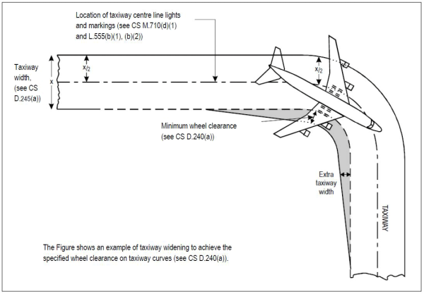
Figure GM-D-1. Taxiway curve
[Issue: ADR-DSN/3]
CS ADR-DSN.D.255 Junction and intersection of taxiways
ED Decision 2014/013/R
(a) To facilitate the movement of aeroplanes, fillets should be provided at junctions and intersections of taxiways with runways, aprons, and other taxiways.
(b) The design of the fillets should ensure that the minimum wheel clearances specified in CS ADR-DSN.D.240 are maintained when aeroplanes are manoeuvring through the junctions or intersections.
GM1 ADR-DSN.D.255 Junction and intersection of taxiways
ED Decision 2016/027/R
Consideration should be given to the aeroplane datum length when designing fillets. Guidance on the design of fillets and the definition of the term aeroplane datum length are given in ICAO Doc 9157, Aerodrome Design Manual, Part 2, Taxiways, Aprons and Holding Bays.
[Issue: ADR-DSN/3]
CS ADR-DSN.D.260 Taxiway minimum separation distance
ED Decision 2017/021/R
(a) The safety objective of minimum taxi separation distances is to allow safe use of taxiways and aircraft stand taxilanes to prevent possible collision with other aeroplanes operating on adjacent runways or taxiways, or collision with adjacent objects.
(b) The separation distance between the centre line of a taxiway and the centre line of a runway, the centre line of a parallel taxiway or an object should not be less than the appropriate dimension specified in Table D-1.
|
|
Distance between taxiway centre line and runway centre line (metres) |
Taxiway centre line to taxiway centre line (metres) |
Taxiway, other than aircraft stand taxilane, centre line to object (metres) |
Aircraft stand taxilane centre line to aircraft stand taxilane centre line (metres) |
Aircraft stand taxilane centre line to object (metres) |
||||||||
|
Instrument runways Code number |
|
Non-instrument runways Code number |
|||||||||||
|
Code letter |
1 |
2 |
3 |
4 |
|
1 |
2 |
3 |
4 |
||||
|
(1) |
(2) |
(3) |
(4) |
(5) |
|
(6) |
(7) |
(8) |
(9) |
(10)
|
(11)
|
(12) |
(13)
|
|
A |
77.5 |
77.5 |
— |
— |
|
37.5 |
47.5 |
— |
— |
23 |
15.5 |
19.5 |
12 |
|
B |
82 |
82 |
152 |
— |
|
42 |
52 |
87 |
— |
32 |
20 |
28.5 |
16.5 |
|
C |
88 |
88 |
158 |
158 |
|
48 |
58 |
93 |
93 |
44 |
26 |
40.5 |
22.5 |
|
D |
— |
— |
166 |
166 |
|
— |
— |
101 |
101 |
63 |
37 |
59.5 |
33.5 |
|
E |
— |
— |
172.5 |
172.5 |
|
— |
— |
107.5 |
107.5 |
76 |
43.5 |
72.5 |
40 |
|
F |
— |
— |
180 |
180 |
|
— |
— |
115 |
115 |
91 |
51 |
87.5 |
47.5 |
|
Note 1: The separation distances shown in columns (2) to (9) represent ordinary combinations of runways and taxiways. Note 2: The distances in columns (2) to (9) do not guarantee sufficient clearance behind a holding aeroplane to permit the passing of another aeroplane on a parallel taxiway. |
|||||||||||||
Table D-1. Taxiway minimum separation distances
[Issue: ADR-DSN/2]
[Issue: ADR-DSN/4]
GM1 ADR-DSN.D.260 Taxiway minimum separation distance
ED Decision 2017/021/R
(a) Guidance on factors which may be considered in the safety assessment is given in ICAO Doc 9157, Aerodrome Design Manual, Part 2, Taxiways, Aprons and Holding Bays.
(b) ILS and MLS installations may also influence the location of taxiways due to interferences to ILS and MLS signals by a taxiing or stopped aircraft. Information on critical and sensitive areas surrounding ILS and MLS installations is contained in ICAO, Annex 10, Volume I, Attachments C and G (respectively).
(c) The separation distances, as prescribed in Table D-1, column (10), do not necessarily provide the capability of making a normal turn from one taxiway to another parallel taxiway. Guidance for this condition is given in ICAO Doc 9157, Aerodrome Design Manual, Part 2, Taxiways, Aprons and Holding Bays.
(d) The separation distance between the centre line of an aircraft stand taxilane and an object, as prescribed in Table D-1, column (13), may need to be increased when jet exhaust wake velocity may cause hazardous conditions for ground servicing.
(e) It may be permissible to operate with lower separation distances at an existing aerodrome if a safety assessment indicates that such lower separation distances would not adversely affect the safety or significantly affect the regularity of operations of aeroplanes.
(f) The separation distances, as prescribed in Table D-1, may have to be increased on taxiway curves to accommodate the wing sweep of the critical aeroplane or on dual parallel taxiways when, as for example, used as bypass taxiways.
(g) The requirements for apron taxiways regarding strip width, separation distances, etc., are the same as for any other type of taxiway.
[Issue: ADR-DSN/2]
[Issue: ADR-DSN/3]
[Issue: ADR-DSN/4]
CS ADR-DSN.D.265 Longitudinal slopes on taxiways
ED Decision 2014/013/R
(a) The safety objective of limiting the longitudinal taxiway slope is to enable stabilised safe use of taxiway by an aircraft.
(b) The longitudinal slope of a taxiway should not exceed:
(1) 1.5 % where the code letter is C, D, E, or F; and
(2) 3 % where the code letter is A or B.
CS ADR-DSN.D.270 Longitudinal slope changes on taxiways
ED Decision 2014/013/R
(a) The safety objective of limiting the longitudinal taxiway slope changes is to avoid damage of aircraft and to enable safe use of taxiway by an aircraft.
(b) Where slope changes on a taxiway cannot be avoided, the transition from one slope to another slope should be accomplished by a curved surface with a rate of change not exceeding:
(1) 1 % per 30 m (minimum radius of curvature of 3 000 m) where the code letter is C, D, E, or F; and
(2) 1 % per 25 m (minimum radius of curvature of 2 500 m) where the code letter is A or B.
(c) Where slope changes in (b)(1) and (2) are not achieved and slopes on a taxiway cannot be avoided, the transition from one slope to another slope should be accomplished by a curved surface which should allow the safe operation of all aircraft in all weather conditions.
GM1 ADR-DSN.D.270 Longitudinal slope changes on taxiways
ED Decision 2014/013/R
intentionally left blank
CS ADR-DSN.D.275 Sight distance of taxiways
ED Decision 2014/013/R
(a) The safety objective of minimum taxiway sight distance values is to achieve the necessary visibility to enable safe use of taxiway by an aircraft.
(b) Where a change in slope on a taxiway cannot be avoided, the change should be such that, from any point:
(1) 3 m above the taxiway, it should be possible to see the whole surface of the taxiway for a distance of at least 300 m from that point where the code letter is C, D, E, or F;
(2) 2 m above the taxiway, it should be possible to see the whole surface of the taxiway for a distance of at least 200 m from that point where the code letter is B; and
(3) 1.5 m above the taxiway, it should be possible to see the whole surface of the taxiway for a distance of at least 150 m from that point where the code letter is A.
CS ADR-DSN.D.280 Transverse slopes on taxiways
ED Decision 2014/013/R
(a) The safety objective of taxiway transverse slopes is to promote the most rapid drainage of water from the taxiway.
(b) The transverse slopes of a taxiway should be sufficient to prevent the accumulation of water on the surface of the taxiway but should not exceed:
(1) 1.5 % where the code letter is C, D, E, or F; and
(2) 2 % where the code letter is A or B.
GM1 ADR-DSN.D.280 Transverse slopes on taxiways
ED Decision 2014/013/R
The slopes on a taxiway are intended to prevent the accumulation of water (or possible fluid contaminant) on the surface and to facilitate rapid drainage of surface water (or possible fluid contaminant). Slopes should be so designed as to minimise impact on aircraft and so not to hamper the operation of aircraft.
CS ADR-DSN.D.285 Strength of taxiways
ED Decision 2014/013/R
The strength of a taxiway should be suitable for the aircraft that the taxiway is intended to serve.
GM1 ADR-DSN.D.285 Strength of taxiways
ED Decision 2022/006/R
(a) Due consideration is to be given to the fact that a taxiway is subjected to a greater density of traffic and as a result of slow moving and stationary aeroplanes, to higher stresses than the runway it serves.
(b) The method for reporting the bearing strength of the pavement is available in Part-ADR.OPS of Regulation (EU) No 139/2014.
(c) Additional information on the bearing strength, the design, and evaluation of pavements is given in ICAO Doc 9157, Aerodrome Design Manual, Part 3, Pavements.
[Issue: ADR-DSN/3]
[Issue: ADR-DSN/6]
CS ADR-DSN.D.290 Surface of taxiways
ED Decision 2016/027/R
(a) The surface of a taxiway should not have irregularities that cause damage to aeroplane structures.
(b) The surface of a paved taxiway should be so constructed or resurfaced as to provide suitable surface friction characteristics.
[Issue: ADR-DSN/3]
GM1 ADR-DSN.D.290 Surface of taxiways
ED Decision 2016/027/R
Suitable surface friction characteristics are those surface properties required on taxiways that assure safe operation of aeroplanes.
[Issue: ADR-DSN/3]
CS ADR-DSN.D.295 Rapid exit taxiways
ED Decision 2014/013/R
(a) The safety objective of rapid exit taxiway is to facilitate safe rapid exit of aeroplanes from a runway.
(b) A rapid exit taxiway should be designed with a radius of turn-off curve of at least:
(1) 550 m where the code number is 3 or 4; and
(2) 275 m where the code number is 1 or 2;
to enable under wet conditions exit speeds of:
(i) 93 km/h where the code number is 3 or 4; and
(ii) 65 km/h where the code number is 1 or 2.
(c) The radius of the fillet on the inside of the curve at a rapid exit taxiway should be sufficient to provide a widened taxiway throat in order to facilitate early recognition of the entrance and turn-off onto the taxiway.
(d) A rapid exit taxiway should include a straight distance after the turn-off curve sufficient for an exiting aircraft to come to a full stop clear of any intersecting taxiway (Figure D-1).
(e) The intersection angle of a rapid exit taxiway with the runway should not be greater than 45°, nor less than 25° and preferably should be 30°.
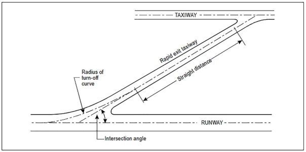
Figure D-1. Rapid exit taxiway
GM1 ADR-DSN.D.295 Rapid exit taxiways
ED Decision 2021/004/R
(a) The following guidance applies particularly to rapid exit taxiways (see Figure D-1). The general requirements for taxiways, as prescribed in the relevant certification specifications, are also applicable to rapid exit taxiways. Guidance on the provision, location and design of rapid exit taxiways is included in ICAO Doc 9157, Aerodrome Design Manual, Part 2, Taxiways, Aprons and Holding Bays.
(b) The locations of rapid exit taxiways along a runway are based on several criteria described in ICAO Doc 9157, Aerodrome Design Manual, Part 2, Taxiways, Aprons and Holding Bays, in addition to different speed criteria.
[Issue: ADR-DSN/3]
[Issue: ADR-DSN/5]
CS ADR-DSN.D.300 Taxiways on bridges
ED Decision 2014/013/R
(a) The width of that portion of a taxiway bridge capable of supporting aeroplanes, as measured perpendicularly to the taxiway centre line, should not be less than the width of the graded area of the strip provided for that taxiway unless a proven method of lateral restraint is provided which should not be hazardous for aeroplanes for which the taxiway is intended.
(b) Access should be provided to allow rescue and firefighting vehicles to intervene in both directions within the specified response time to the largest aeroplane for which the taxiway bridge is intended.
(c) A bridge should be constructed on a straight section of the taxiway with a straight section on both ends of the bridge to facilitate the alignment of aeroplanes approaching the bridge.
GM1 ADR-DSN.D.300 Taxiways on bridges
ED Decision 2014/013/R
If aeroplane engines overhang the bridge structure, protection of adjacent areas below the bridge from engine blast may be required.
CS ADR-DSN.D.305 Taxiway shoulders
ED Decision 2017/021/R
(a) Straight portions of a taxiway where the code letter is C, D, E, or F should be provided with shoulders which extend symmetrically on each side of the taxiway so that the overall width of the taxiway and its shoulders on straight portions is not less than:
(1) 44 m where the code letter is F;
(2) 38 m where the code letter is E;
(3) 34 m where the code letter is D; and
(4) 25 m where the code letter is C.
(b) On taxiway curves and on junctions or intersections where increased pavement is provided, the shoulder width should be not less than that on the adjacent straight portions of the taxiway.
(c) When a taxiway is intended to be used by turbine-engined aeroplanes, the surface of the taxiway shoulder should be prepared so as to resist erosion and the ingestion of the surface material by aeroplane engines.
[Issue: ADR-DSN/4]
GM1 ADR-DSN.D.305 Taxiway shoulders
ED Decision 2016/027/R
Guidance on characteristics of taxiway shoulders and on shoulder treatment is given in ICAO Doc 9157, Aerodrome Design Manual, Part 2, Taxiways, Aprons and Holding Bays.
[Issue: ADR-DSN/3]
CS ADR-DSN.D.310 Taxiway Strip
ED Decision 2014/013/R
A taxiway, other than an aircraft stand taxilane, should be included in a strip.
GM1 ADR-DSN.D.310 Taxiway Strip
ED Decision 2016/027/R
A taxiway strip should be so prepared or constructed as to minimise hazards arising from differences in load bearing capacity to aeroplanes which the taxiway is intended to serve in the event of an aeroplane accidentally running off the taxiway.
Guidance on characteristics of taxiway strips is given in ICAO Doc 9157, Aerodrome Design Manual, Part 2, Taxiways, Aprons and Holding Bays.
[Issue: ADR-DSN/3]
CS ADR-DSN.D.315 Width of taxiway strips
ED Decision 2016/027/R
(a) The safety objective of the width of taxiway strips is to allow safe use of taxiways in relation to adjacent objects.
(b) A taxiway strip should extend symmetrically on each side of the centre line of the taxiway throughout the length of the taxiway to at least the distance from the centre line given in Table D-1, column (11).
[Issue: ADR-DSN/3]
CS ADR-DSN.D.320 Objects on taxiway strips
ED Decision 2014/013/R
The taxiway strip should provide an area clear of objects which may endanger taxiing aeroplanes.
GM1 ADR-DSN.D.320 Objects on taxiway strips
ED Decision 2017/021/R
(a) Consideration should be given to the location and design of drains on a taxiway strip to prevent damage to an aeroplane accidentally running off a taxiway. Suitably designed drain covers may be required.
(b) The detailed requirements for siting objects on taxiway strips are in CS ADR-DSN.T.915.
(c) Where open-air or covered storm water conveyances are installed, consideration should be given in order to ensure that their structure does not extend above the surrounding ground so as not to be considered an obstacle.
(d) Particular attention needs to be given to the design and maintenance of an open-air storm water conveyance in order to prevent wildlife attraction, in particular birds. The open-air storm water conveyance may be covered by a net, if required. Further guidance is given in ICAO Doc 9137, Airport Services Manual, Part 3, Wildlife Control and Reduction.
(e) Guidance on the design of drain covers is given in ICAO Doc 9157, Aerodrome Design Manual, Part 2, Taxiways, Aprons and Holding Bays.
[Issue: ADR-DSN/4]
CS ADR-DSN.D.325 Grading of taxiway strips
ED Decision 2017/021/R
(a) The safety objective of the grading of a taxiway strip is to reduce the risk of damage to an aircraft accidentally running off the taxiway.
(b) The centre portion of a taxiway strip should provide a graded area to a distance from the centre line of the taxiway of not less than that given by the following tabulation:
(1) 10.25 m where the OMGWS is up to but not including 4.5 m;
(2) 11 m where the OMGWS is 4.5 m up to but not including 6 m;
(3) 12.50 m where the OMGWS is 6 m up to but not including 9 m;
(4) 18.50 m where the OMGWS is 9 m up to but not including 15 m, where the code letter is D;
(5) 19 m where the OMGWS is 9 m up to but not including 15 m, where the code letter is E;
(6) 22 m where the OMGWS is 9 m up to but not including 15 m, where the code letter is F.
[Issue: ADR-DSN/4]
GM1 ADR-DSN.D.325 Grading of taxiway strips
ED Decision 2017/021/R
Further guidance on the width of the graded portion of a taxiway is given in ICAO Doc 9157, Aerodrome Design Manual, Part 2, Taxiways, Aprons and Holding Bays.
[Issue: ADR-DSN/4]
CS ADR-DSN.D.330 Slopes on taxiway strips
ED Decision 2014/013/R
(a) The safety objective of limiting the longitudinal taxiway strip slopes and slope changes and of minimum sight distances values is to reduce the probability of damage to an aircraft accidentally running off the taxiway and to enable safe use of these areas by rescue and firefighting vehicles.
(b) The surface of the strip should be flush at the edge of the taxiway or shoulder if provided, and the graded portion should not have an upward transverse slope exceeding:
(1) 2.5 % for strips where the code letter is C, D, E, or F; and
(2) 3 % for strips of taxiways where the code letter is A or B;
the upward slope being measured with reference to the transverse slope of the adjacent taxiway surface and not the horizontal. The downward transverse slope should not exceed 5 % measured with reference to the horizontal.
(c) The transverse slopes on any portion of a taxiway strip beyond that to be graded should not exceed an upward or downward slope of 5 % as measured in the direction away from the taxiway.
GM1 ADR-DSN.D.330 Slopes on taxiway strips
ED Decision 2017/021/R
(a) Where required for proper drainage, an open-air storm water conveyance may be allowed in the non-graded portion of a taxiway strip and should be placed as far as practicable from the taxiway.
(b) The locations of open-air storm water conveyances within the non-graded portion of a taxiway strip should be so designed to permit unobstructed access for rescue and firefighting services (RFFS).
[Issue: ADR-DSN/4]
CS ADR-DSN.D.335 Holding bays, runway-holding positions, intermediate holding positions, and road-holding positions
ED Decision 2016/027/R
(a) Holding bay(s) or other bypasses of sufficient size and adequate construction should be provided where necessary, to make deviations in the departure sequence possible.
(b) A runway-holding position or positions should be established:
(1) on the taxiway, if the location or alignment of the taxiway is such that a taxiing aircraft or vehicle can infringe an obstacle limitation surface or ILS/MLS critical/sensitive area or interfere with the operation of radio navigation aids;
(2) on the taxiway, at the intersection of a taxiway and a runway; and
(3) at an intersection of a runway with another runway when the former runway is part of a standard taxi-route.
(c) An intermediate holding position should be established on a taxiway at any point other than a runway-holding position where it is desirable to define a specific holding limit.
(d) An emergency access road should be equipped with road-holding positions at all intersections with runways and taxiways.
(e) A road-holding position should be established at each intersection of a road with a runway.
[Issue: ADR-DSN/3]
GM1 ADR-DSN.D.335 Holding bays, runway-holding positions, intermediate holding positions, and road-holding positions
ED Decision 2016/027/R
(a) At low levels of aerodrome activity (less than approximately 50 000 annual operations), there is normally little need to make deviations in the departure sequence. However, for higher activity levels, aerodromes with single taxiways and no holding bays or other bypasses provide aerodrome control units with no opportunity to change the sequence of departures once the aircraft have left the apron. In particular, at aerodromes with large apron areas, it is often difficult to arrange for aircraft to leave the apron in such a way that they should arrive at the end of the runway in the sequence required by air traffic services units.
(b) The provision of an adequate number of holding bay spaces or other bypasses, based upon an analysis of the current and near-term hourly aircraft departure demand, should allow a large degree of flexibility in generating the departure sequence.
(c) The space required for a holding bay depends on the number of aircraft positions to be provided, the size of the aircraft to be accommodated, and the frequency of their utilisation. The dimensions should allow for sufficient space between aircraft to enable them to manoeuvre independently.
(d) Emergency access roads are not intended for use for the functions of aerodrome service roads. However, they should be provided by different access controls which should be clearly visible for all service ground traffic.
(e) Further guidance is given in ICAO Doc 9157, Aerodrome Design Manual, Part 2, Taxiways, Aprons and Holding Bays and ICAO Doc 4444, Procedures for Air Navigation Services — Air Traffic Management.
[Issue: ADR-DSN/3]
CS ADR-DSN.D.340 Location of holding bays, runway-holding positions, intermediate holding positions, and road-holding positions
ED Decision 2022/006/R
(a) The distance between a holding bay, runway-holding position established at a taxiway/runway intersection or road-holding position and the centre line of a runway should be in accordance with Table D-2 and such that a holding aircraft or vehicle should not interfere with the operation of radio navigation aids or penetrate the inner transitional surface.
(b) At elevations greater than 700 m the distance of 90 m specified in Table D-2 for a precision approach runway code number 4 should be increased as follows:
(1) up to an elevation of 2 000 m; 1 m for every 100 m in excess of 700 m;
(2) elevation in excess of 2 000 m and up to 4 000 m; 13 m plus 1.5 m for every 100 m in excess of 2 000 m; and
(3) elevation in excess of 4 000 m and up to 5 000 m; 43 m plus 2 m for every 100 m in excess of 4 000 m.
(c) The location of a runway-holding position established in accordance with CS ADR-DSN.D.335 should be such that a holding aircraft or vehicle will not infringe the obstacle-free zone, approach surface, take-off climb surface or ILS/MLS critical/sensitive area or interfere with the operation of radio navigation aids.
|
Type of runway |
Code numberd |
|||
|
1 |
2 |
3 |
4 |
|
|
Non-instrument |
30 m |
40 m |
75 m |
75 m |
|
Non-precision approach |
40 m |
40 m |
75 m |
75 m |
|
Precision approach Category I |
60 mb |
60 mb |
90 ma,b |
90 ma,b,c |
|
Precision approach Categories II and III |
— |
— |
90 ma,b |
90 ma,b,c |
|
Take-off runway |
30 m |
40 m |
75 m |
75 m |
|
a. If a holding bay, runway-holding position, or road-holding position is at a lower elevation compared to the threshold, the distance may be decreased 5 m for every metre the bay or holding position is lower than the threshold, contingent upon not infringing the inner transitional surface. b. This distance may need to be increased to avoid interference with radio navigation aids, particularly the glide path and localiser facilities (see CS ADR-DSN.D.340). Note 1: The distance of 90 m for code number 3 or 4 is based on an aircraft with a tail height of 20 m, a distance from the nose to the highest part of the tail of 52.7 m and a nose height of 10 m holding at an angle of 45° or more with respect to the runway centre line, being clear of the obstacle-free zone and not accountable for the calculation of OCA/H. Note 2: The distance of 60 m for code number 2 is based on an aircraft with a tail height of 8 m, a distance from the nose to the highest part of the tail of 24.6 m and a nose height of 5.2 m holding at an angle of 45° or more with respect to the runway centre line, being clear of the obstacle-free zone. c. Where the code letter is F, this distance should be at least 100 m. Note: The distance of 100 m for code number 4 where the code letter is F is based on an aircraft with a tail height of 24 m, a distance from the nose to the highest part of the tail of 62.2 m and a nose height of 10 m holding at an angle of 45° or more with respect to the runway centre line, being clear of the obstacle-free zone. d. Elevation of taxiway should be taken into account for possible increase of the distances indicated in this table. |
||||
Table D-2. Minimum distance from the runway centre line to a holding bay, runway-holding position, or road-holding position
[Issue: ADR-DSN/3]
[Issue: ADR-DSN/6]
GM1 ADR-DSN.D.340 Location of holding bays, runway-holding positions, intermediate holding positions, and road-holding positions
ED Decision 2022/006/R
(a) Care should be taken so that propeller wash and jet blast from holding aircraft do not interfere with aircraft operations, cause damage to vehicles, or injure people.
(b) Generally, when used to allow flexible departure sequencing, the most advantageous location for a holding bay is adjacent to the taxiway serving the runway end. Other locations along the taxiway are satisfactory for aircraft performing pre-flight checks or engine run-ups, or as a holding point for aircraft awaiting departure clearance.
(c) An aircraft taxiing could endanger aircraft operations when the aircraft is too close to the runway during take-off and landings. It is so advised to check if the aircraft taking off or landing could be hinder. For this OLS and specially approach surfaces, take-off climb surfaces and OFZ are the first aspects to consider. An aircraft taxiing could also endanger aircraft operations when the aircraft location and orientation are so that the aircraft interfere with navigation aids. It is specific to instrument runways and especially important for precision approach runways. The non-penetration of critical/sensitive areas is the first check. The areas within which this degradable interference of course or path signals are possible need to be defined and recognised. For the purposes of developing protective zoning criteria for ILS, these areas are critical areas and sensitive areas. The ILS critical area is an area of defined dimensions about the localizer and glide path antennas where vehicles, including aircraft, are excluded during all ILS operations. The critical area is protected, since the presence of vehicles and/or aircraft inside the critical area boundaries would cause unacceptable disturbance to the ILS signal. The ILS sensitive area is an area extending beyond the critical area where the parking and/or movement of vehicles, including aircraft, is controlled to prevent the possibility of unacceptable interference to the ILS signal during ILS operations.
(d) For all runways, it should be verified that the distance between a holding bay, runway-holding position established at a taxiway/runway intersection or road-holding position and the centre line of a runway is so that a holding aircraft or vehicle should not infringe the approach surface and/or take-off climb surface.
(e) If the affected runway is used under precision approach procedures, it should be also verified that the distance between a holding bay, runway-holding position established at a taxiway/runway intersection or road-holding position and the centre line of a runway is so that a holding aircraft or vehicle should not infringe the obstacle-free zone and the critical/sensitive areas of precision approach navigation aids (e.g. ILS/MLS).
(f) If a holding bay, runway-holding position or road-holding position for a precision approach runway code number 4 is at a greater elevation compared to the threshold, the distance specified in Table D-2 could be further increased 5 m for every metre the bay or position is higher than the threshold.
(g) An aircraft taxiing could also endanger aircraft operation when the aircraft is too close to other taxiing aircraft. For this, separation distances or margins between taxiing aircraft or taxiways should be considered.
(h) In radiotelephony phraseologies, the expression ‘holding point’ is used to designate the runway-holding position.
(i) Further guidance is given in ICAO Doc 9157, Aerodrome Design Manual, Part 2, Taxiways, Aprons and Holding Bays.
[Issue: ADR-DSN/3]
[Issue: ADR-DSN/6]