
Regulation (EU) No 139/2014
The aerodrome operator shall as appropriate:
(a) determine, document and maintain data relevant to the aerodrome and available services;
(b) provide data relevant to the aerodrome and available services to the users and the relevant air traffic services and aeronautical information services providers.
AMC1 ADR.OPS.A.005 Aerodrome data
ED Decision 2014/012/R
(a) Data relevant to the aerodrome and available services should include, but may not be limited to, items in the following list:
(1) aerodrome reference point;
(2) aerodrome and runway elevations;
(3) aerodrome reference temperature;
(4) aerodrome dimensions and related information;
(5) strength of pavements;
(6) pre-flight altimeter check location;
(7) declared distances;
(8) condition of the movement area and related facilities;
(9) disabled aircraft removal;
(10) rescue and firefighting; and
(11) visual approach slope indicator systems.
(b) The aerodrome operator should measure and report to the aeronautical information services obstacles and terrain data in Area 3, and in Area 2 (the part within the aerodrome boundary) in degrees, minutes, seconds and tenths of seconds. In addition, the top elevation, type, marking and lighting (if any) of obstacles should be reported to the aeronautical information services.
(c) Electronic obstacle data for all obstacles in Area 2 (the part within the aerodrome boundary) that are assessed as being a hazard to air navigation should be provided.
(d) Electronic terrain and obstacle data should be provided for:
(1) Area 2a, for those that penetrate the relevant obstacle data collection surface;
(2) penetrations of the take-off flight path area obstacle identification surfaces; and
(3) penetrations of the aerodrome obstacle limitation surfaces.
(e) Electronic terrain and obstacle data should be provided for Area 4 for terrain and obstacles that penetrate the relevant obstacle data collection surface, for all runways where precision approach Category II or III operations have been established and where detailed terrain information is required by operators to enable them to assess the effect of terrain on decision height determination by use of radio altimeters.
(f) The aerodrome operator should establish arrangements with the Air Traffic Services providers and the Competent Authority for the provision of obstacles and terrain data outside of the aerodrome boundary.
GM1 ADR.OPS.A.005 Aerodrome data
ED Decision 2021/003/R
AERODROME REFERENCE POINT
(a) The aerodrome reference point should be located near the initial or planned geometric centre of the aerodrome and normally should remain where first established.
(b) The aerodrome reference point should be measured and reported to the aeronautical information services in degrees, minutes, and seconds.
AERODROME AND RUNWAY ELEVATIONS
The following should be measured and reported to the aeronautical information services:
(a) The aerodrome elevation and geoid undulation at the aerodrome elevation position to the accuracy of one-half metre or foot;
(b) For non-precision approaches, the elevation and geoid undulation of each threshold, the elevation of the runway end and any significant high and low intermediate points along the runway, to the accuracy of one-half metre or foot;
(c) For precision approach runway, the elevation and geoid undulation of the threshold, the elevation of the runway end and the highest elevation of the touchdown zone, to the accuracy of one-quarter metre or foot.
AERODROME REFERENCE TEMPERATURE
(a) The aerodrome reference temperature should be determined in degrees Celsius.
(b) The aerodrome reference temperature should be the monthly mean of the daily maximum temperatures for the hottest month of the year (the hottest month being that which has the highest monthly mean temperature), averaged over a period of five (5) years.
AERODROME DIMENSIONS AND RELATED INFORMATION
The following data are measured or described, as appropriate, for each facility provided on the aerodrome:
(a) Runway
(1) true bearing to one-hundredth of a degree;
(2) designation number;
(3) length;
(4) width;
(5) displaced threshold location to the nearest metre or foot;
(6) longitudinal slope;
(7) surface type;
(8) type of runway; and
(9) for a precision approach runway category I, the existence of an obstacle free zone when provided.
(b) Strip/Runway End Safety Area/Stopway
(1) Length, width to the nearest metre or foot;
(2) Surface type; and
(3) Arresting system – location (which runway end) and description.
(c) Taxiway
(1) Designation;
(2) Width; and
(3) Surface type.
(d) Apron
(1) Surface type; and
(2) Aircraft stands.
(e) The boundaries of the air traffic control service;
(f) Clearway
(1) length to the nearest metre or foot; and
(2) ground profile.
(g) Visual aids for approach procedures, marking and lighting of runways, taxiways and aprons, other visual guidance and control aids on taxiways and aprons, including runway holding positions, intermediate holding positions and stopbars, and location and type of visual docking guidance systems;
(h) Location and radio frequency of any VOR aerodrome checkpoint;
(i) Location and designation of standard taxi-routes;
(j) Distances to the nearest metre or foot of localiser and glide path elements comprising an instrument landing system (ILS) or azimuth and elevation antenna of a microwave landing system (MLS) in relation to the associated runway extremities;
(k) The geographical coordinates of:
(1) each threshold;
(2) appropriate taxiway centre line points; and
(3) each aircraft stand;
are measured and reported to the aeronautical information services in degrees, minutes, seconds and hundredths of seconds.
STRENGTH OF PAVEMENTS
(a) The bearing strength of a pavement intended for aircraft of apron (ramp) mass greater than 5 700 kg should be made available using the aircraft classification — pavement classification number (ACN–PCN) method, by reporting all of the following information:
(1) the pavement classification number (PCN);
(2) pavement type for ACN-PCN determination;
(3) subgrade strength category;
(4) maximum allowable tire pressure category or maximum allowable tire pressure value; and
(5) evaluation method.
(b) For the purposes of determining the ACN, the behaviour of a pavement should be classified as equivalent to a rigid or flexible construction;
(c) Information on pavement type for ACN-PCN determination, subgrade strength category, maximum allowable tire pressure category and evaluation method, should be reported using the following codes:
(1) Pavement type for ACN-PCN determination:
(i) Rigid pavement: Code R;
(ii) Flexible pavement: Code F;
(2) Subgrade strength category:
(i) High strength: characterised by K = 150 MN/m3 and representing all K values above 120 MN/m3 for rigid pavements, and by CBR = 15 and representing all CBR values above 13 for flexible pavements — Code A;
(ii) Medium strength: characterised by K = 80 MN/m3 and representing a range in K of 60 to 120 MN/m3 for rigid pavements, and by CBR = 10 and representing a range in CBR of 8 to 13 for flexible pavements — Code B;
(iii) Low strength: characterised by K = 40 MN/m3 and representing a range in K of 25 to 60 MN/m3 for rigid pavements, and by CBR = 6 and representing a range in CBR of 4 to 8 for flexible pavements — Code C;
(iv) Ultra low strength: characterised by K = 20 MN/m3 and representing all K values below 25 MN/m3 for rigid pavements, and by CBR = 3 and representing all CBR values below 4 for flexible pavements — Code D;
(3) Maximum allowable tire pressure category:
(i) Unlimited: no pressure limit — Code W;
(ii) High: pressure limited to 1.75 MPa — Code X;
(iii) Medium: pressure limited to 1.25 MPa — Code Y;
(iv) Low: pressure limited to 0.50 MPa — Code Z;
(4) Evaluation method:
(i) Technical evaluation: representing a specific study of the pavement characteristics and application of pavement behaviour technology — Code T;
(ii) Using aircraft experience: representing a knowledge of the specific type and mass of aircraft satisfactorily being supported under regular use — Code U;
(d) The bearing strength of a pavement intended for aircraft of apron (ramp) mass equal to or less than 5 700 kg, should be reported by reporting the following information:
(1) maximum allowable aircraft mass; and
(2) maximum allowable tire pressure.
PRE-FLIGHT ALTIMETER CHECK LOCATION
(a) One or more pre-flight altimeter check locations should be established.
(b) The elevation of a pre-flight altimeter check location should be given as the average elevation, rounded to the nearest metre or foot, of the area on which it is located. The elevation of any portion of a pre-flight altimeter check location should be within 3 m (10 ft) of the average elevation for that location.
(c) Pre-flight check location could be located on an apron. Locating a pre-flight altimeter check location on an apron enables an altimeter check to be made prior to obtaining taxi clearance and eliminates the need for stopping for that purpose after leaving the apron. Normally an entire apron could serve as a satisfactory altimeter check location.
DECLARED DISTANCES
(a) The following distances should be calculated to the nearest metre or foot for a runway and reported to the aeronautical information services and Air Traffic Services:
(1) Take-off run available (TORA);
(2) Take-off distance available (TODA);
(3) Accelerate stop distance available (ASDA); and
(4) Landing distance available (LDA).
(b) The take-off run available (TORA), take-off distance available (TODA), accelerate stop distance available (ASDA) and landing distance available (LDA) should be calculated according to the following (all declared distances are illustrated for operations from left to right):
(1) Where a runway is not provided with a stopway or a clearway and the threshold is located at the extremity of the runway, the four declared distances should normally be equal to the length of the runway
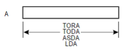
Figure 1
(2) When a runway is provided with a clearway (CWY), then the TODA will include the length of clearway.
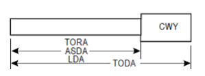
Figure 2
(3) Where a runway is provided with a stopway (SWY), then the ASDA will include the length of stopway.
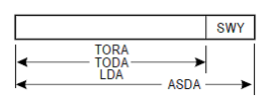
Figure 3
(4) Where a runway has a displaced threshold, then the LDA will be reduced by the distance the threshold is displaced. A displaced threshold affects only the LDA for approaches made to that threshold; all declared distances for operations in the reciprocal direction are unaffected.
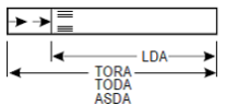
Figure 4
(5) Where a runway is provided with more than one of the clearway, stopway, or having a displaced threshold, then more than one of the declared distances will be modified. The modification will follow the same principle as in (1)–(4)
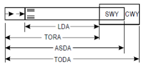
Figure 5
(c) The information on declared distances should be provided according to the following table:
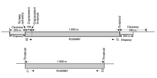
Figure 6
|
RUNWAY |
TORA |
ASDA |
TODA |
LDA |
|
|
m |
m |
m |
m |
|
09 27 17 35 |
2 000 2 000 NU 1 800 |
2 300 2 350 NU 1 800 |
2 580 2 350 NU 1 800 |
1 850 2 000 1 800 NU |
Table 1
If a runway direction cannot be used for take-off or landing, or both because it is operationally forbidden, then this should be declared and the words ‘not usable’ or the abbreviation ‘NU’ entered.
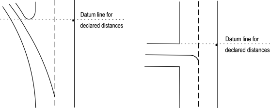
(d) When intersection take-offs are performed, the datum line from which the reduced runway declared distances for take-off are determined, should be defined by the intersection of the downwind edge as shown in the figure below:
CONDITION OF THE MOVEMENT AREA AND RELATED FACILITIES
The condition of the movement area and the operational status of related facilities need to be monitored and reported, on matters of operational significance affecting aircraft and aerodrome operations, particularly in respect of the following:
(a) construction or maintenance work;
(b) rough or broken surfaces on a runway, a taxiway or an apron;
(c) other temporary hazards, including parked aircraft;
(d) failure or irregular operation of part or all the aerodrome visual aids; and
(e) failure of the normal or secondary power supply.
DISABLED AIRCRAFT REMOVAL
(a) The contact details (telephone/telex number(s), email address, etc.) of the office of the aerodrome coordinator of operations for the removal of an aircraft disabled on or adjacent to the movement area should be made available on request to aircraft operators.
(b) Information concerning the capability to remove an aircraft disabled on or adjacent to the movement area should be made available.
(c) The capability to remove a disabled aircraft may be expressed in terms of the largest type of aircraft which the aerodrome is equipped to remove.
RESCUE AND FIREFIGHTING
(a) Information concerning the level of protection provided at an aerodrome for aircraft rescue and firefighting purposes during the hours of operation should be made available.
(b) The level of protection normally available at the aerodrome should be expressed in terms of the category of the rescue and firefighting services and in accordance with the types and amounts of extinguishing agents normally available at the aerodrome.
(c) Changes in the level of protection normally available at the aerodrome for rescue and firefighting should be notified to the appropriate air traffic services units and aeronautical information services units to enable those units to provide the necessary information to arriving and departing aircraft. When such a change has been corrected, the above units should be advised accordingly.
(d) Changes in the level of protection from that normally available at the aerodrome could result from a change in the availability of extinguishing agents, equipment to deliver the agents or personnel to operate the equipment, etc.
(e) A change in the level of protection is expressed in terms of the new category of the rescue and firefighting services available at the aerodrome.
VISUAL APPROACH SLOPE INDICATOR SYSTEMS
The following information concerning a visual approach indicator system is made available:
(a) associated runway designation number;
(b) type of system; for a PAPI or APAPI installation, the side of the runway on which the lights are installed, i.e. left or right, is given;
(c) where the axis of the system is not parallel to the runway centre line, the angle of displacement and the direction of displacement, i.e. left or right, is indicated;
(d) nominal approach slope angle(s); and
(e) minimum eye height(s) over the threshold of the on-slope signal(s).
GM2 ADR.OPS.A.005(a) Aerodrome data
ED Decision 2014/012/R
SURVEYING REQUIREMENTS FOR RUNWAY THRESHOLDS, TAXIWAYS AND AIRCRAFT STANDS
(a) Thresholds
(1) For surveying purposes, threshold positions must be taken as being at the geometric centre of the runway and at the beginning of the paved surface, i.e. the beginning of that portion of the runway usable for landing. Where thresholds are marked by appropriate threshold markings (e.g. displaced thresholds), these must be taken as the threshold points. Where threshold lighting is surveyed, the locations must be described on the diagram accompanying the report. Where there is no threshold lighting, an appropriate point for survey in accordance with the following figures must be selected.
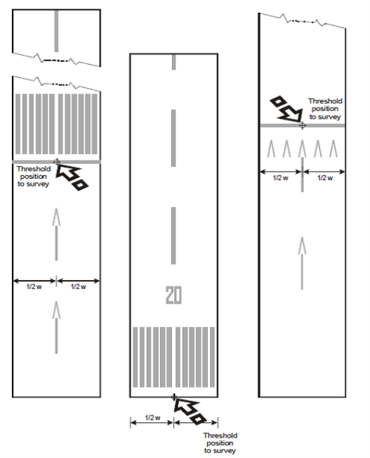
Figure 1
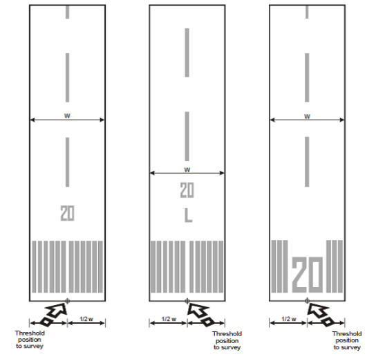
Figure 2
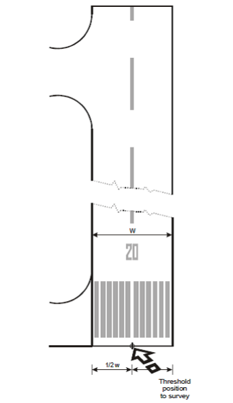
Figure 3
(2) If the runway has only one threshold certified for landing, the runway end position must be surveyed. For surveying purposes, the runway end position (flight path alignment point) must be taken as being at the geometric centre of the runway and at the end of the paved surface, i.e. the end of that portion of the runway usable for landing.
(b) Taxiways and stand/checkpoints — General
(1) Except as provided in (c) (1) below, for surveying purposes the centre (mid-width) of the taxiway centre line marking, apron taxilane marking or the aircraft stand guide line marking must be taken as the reference data.
(2) The points of commencement and ends of straight sections of taxiways, apron taxilanes and aircraft stand point guidance lines markings must be surveyed. Sufficient additional points must be surveyed to maintain the required accuracy along the lines.
(3) For curved sections of taxiways, apron taxilanes and aircraft stand guide line markings, the commencement and end of the curved section centre line must be surveyed together with the position of the centre point of the arc and its radius. In the case of a compound curve, the centre and radius of each arc and the commencement and end of each of the arcs must be surveyed. Where this is impracticable in the field, a series of sequential points must be surveyed along the curved section of the centre line with a maximum arc to chord distance not exceeding 0.25 m for taxiways and 0.10 m for apron taxilanes and aircraft stand guide line markings. Sufficient points must be surveyed to maintain the required accuracy along the lines. The surveyor must, in processing the data, conduct a graphical inspection of the survey points to ensure collinearity.
(c) Taxiways
(1) To permit uninterrupted transition from the actual runway centre line to the taxiway centre line and to provide the required continuity of guidance for the aircraft navigation data base, differentiation must be made between the surface markings and the actual path the aircraft must follow. Therefore, for the guidance of aircraft entering or exiting the runway for take-off or landing, the following must be surveyed:
(i) the point at which the radius of turn, prescribed by the appropriate authority for each taxiway, is tangential to the runway centre line, and the point at which that radius of turn joins the taxiway centre line marking at a tangent;
(ii) the point that prescribes the centre of the arc; and
(iii) the radius of the arc.
Where this is impracticable in the field, a series of sequential points must be surveyed along the curved section of the centre line of taxiways.
(2) Where taxiway centre line marking is provided on a runway that is part of a standard taxi route, or a taxiway centre line is not coincident with runway centre line, the following points must be surveyed:
(i) the point on the taxiway marking at which the taxiway enters the runway;
(ii) the points at which the taxiway deviates from a straight line;
(iii) the intersection of the taxiway centre line marking and boundary of each ‘block’ that has been published as part of the aerodrome movement and guidance control system; and
(iv) the point on the taxiway marking at which the taxiway exits the runway.
(3) In defining taxiways, the following points must be surveyed at the centre of the centre line marking of each taxiway, as appropriate:
(i) intermediate holding positions and runway holding positions (including those associated with the intersection of a runway with another runway when the former runway is part of a standard taxi route) and for points established for the protection of sensitive areas for radio navigation aids;
(ii) taxiway intersection markings;
(iii) intersection of other taxiways, including taxiways described in point (c) (2) above;
(iv) intersections of ‘blocks’ defined for surface movement, guidance and control systems;
(v) commencement and end of selectable taxiway lighting systems provided as part of the surface movement, guidance and control systems, where different from subparagraph (iv) above; and
(d) Aircraft stand points
(1) In defining the aircraft stands, the following points must be surveyed at the centre of the guide line marking of the aircraft stands, as appropriate:
(i) taxilane centre lines;
(ii) lead-in line(s);
(iii) turning line;
(iv) straight section of the turning line;
(v) nose wheel stopping position;
(vi) true heading of the alignment bar; and
(vii) lead-out line(s).
(2) Where aircraft stands are utilized by more than one aircraft type and different guide line markings exist, a diagram must be prepared by the surveyor showing the arrangement of the markings in use, together with an indication of the points surveyed. Where all the stands at an aerodrome/heliport are marked uniformly, only a single diagram needs to be prepared.
The points that should be surveyed for a taxiway or an aircraft stand, are shown in the following diagrams:
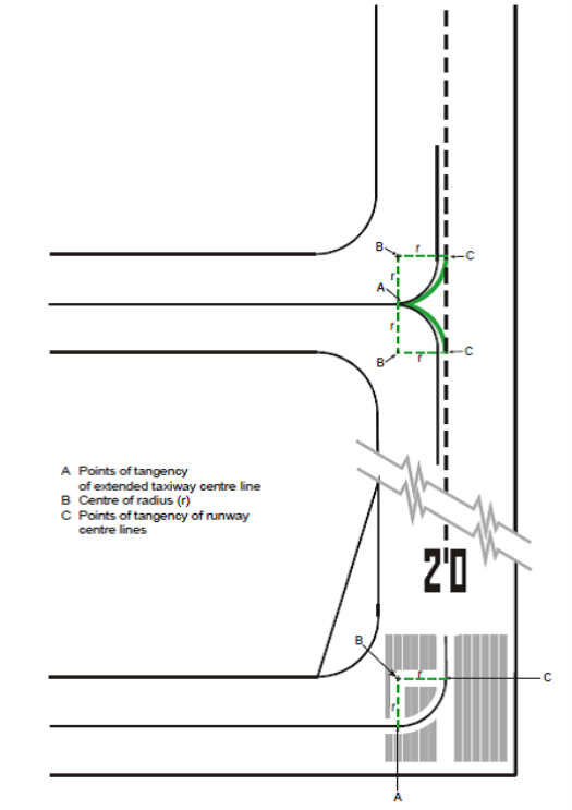
Figure 4 - Runway and taxiway intersections to be surveyed
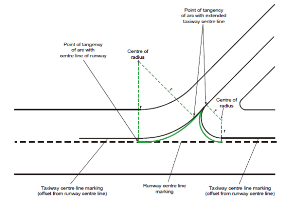
Figure 5 - Runway and taxiway intersections to be surveyed
Figure 6 - Runway holding positions to be surveyed
Figure 7 - Taxiway intersections to be surveyed
Figure 8 - Simple nose wheel lead-in line
|
Position |
Description of point to be surveyed |
|
A |
Point of tangency of centre of lead-in marking with centre of taxilane marking |
|
B |
Centre of arc of lead-in line and radius |
|
C |
Point of tangency with centre of lead-in line marking |
|
D |
Centre of arc of lead-in line and radius |
|
E |
Point of tangency of centre of lead-in marking with centre of taxilane marking |
|
F |
Nose wheel position of parked aircraft |
|
G |
End of lead-in line marking |
Table 1
Figure 9 - Offset nose wheel lead-in line
|
Position |
Description of point to be surveyed |
|
H |
Intersection of centre of lead-in line marking and centre of taxilane marking |
|
I |
Centre of arc of lead-in line and radius |
|
J |
Centre of commencement of straight section of lead-in line |
|
K |
Intersection of centre of lead-in line marking and centre of taxilane marking |
|
L |
Centre of arc of lead-in line and radius |
|
M |
Nosewheel position of parked aircraft |
|
N |
End of lead-in line marking |
Table 2
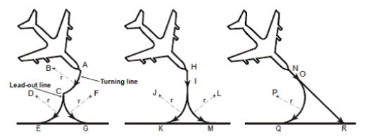
Figure 10 - Simple nose wheel lead-out lines
|
Position |
Description of point to be surveyed |
|
A |
Centre of commencement of turning line marking |
|
B |
Centre of arc of turning line and radius |
|
C |
Centre of intersection of turning line marking and lead-out line marking |
|
D |
Centre of arc of lead-out line and radius |
|
E |
Point of tangency of centre of lead-out line marking and taxilane marking |
|
F |
Centre of arc of lead-out line and radius |
|
G |
Point of tangency of centre of lead-out line marking and taxilane marking |
|
H |
Commencement of lead-out line |
|
I |
Centre of commencement of curved section of lead-out line |
|
J |
Centre of arc of lead-out line and radius |
|
K |
Point of tangency of centre of lead-out line marking and taxilane marking |
|
L |
Centre of arc of lead-out line and radius |
|
M |
Point of tangency of centre of lead-out line marking and taxilane marking |
|
N |
Point of tangency of centre of lead-out line marking and taxilane marking |
|
O |
Centre of commencement of curved section of lead-out line |
|
P |
Centre of arc of lead-out line and radius |
|
Q |
Point of tangency of centre of lead-out line marking and taxilane marking |
|
R |
Intersection of centre of lead-out line marking and taxilane marking |
Table 3
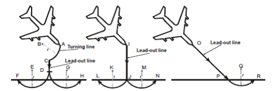
Figure 11 - Offset nose wheel lead-out lines
|
Position |
Description of point to be surveyed |
|
A |
Centre of commencement of turning line marking |
|
B |
Centre of arc of turning line and radius |
|
C |
Centre of intersection of turning line marking and lead-out line marking |
|
D |
Centre of end of straight section of lead-out line marking |
|
E |
Centre of arc of lead-out line and radius |
|
F |
Intersection of centre of lead-out line marking and taxilane marking |
|
G |
Centre of arc of lead-out line and radius |
|
H |
Intersection of centre of lead-out line marking and taxilane marking |
|
I |
Commencement of lead-out line |
|
J |
Centre of commencement of curved section of lead-out line |
|
K |
Centre of arc of lead-out line and radius |
|
L |
Intersection of centre of lead-out line marking and taxilane marking |
|
M |
Centre of arc of lead-out line and radius |
|
N |
Intersection of centre of lead-out line marking and taxilane marking |
|
O |
Commencement of lead-out line |
|
P |
Centre of commencement of curved section of lead-out line |
|
Q |
Centre of arc of lead-out line and radius |
|
R |
Intersection of centre of lead-out line marking and taxilane marking |
Table 4
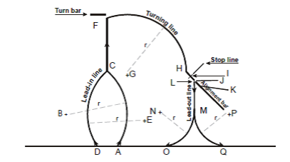
Figure 12 - Turning lines
|
Position |
Description of point to be surveyed |
|
A |
Intersection of centre of lead-in line marking and centre of taxilane marking |
|
B |
Centre of arc of lead-in line and radius |
|
C |
Centre of commencement of straight section of lead-in line |
|
D |
Intersection of centre of lead-in line marking and centre of taxilane marking |
|
E |
Centre of arc of lead-in line and radius |
|
F |
End of straight section of lead-in line marking/commencement of turning line marking |
|
G |
Centre of arc of turning line and radius |
|
H |
Centre of commencement of straight section of turning line marking |
|
I |
Nose wheel position of parked aircraft |
|
J |
Centre of end of straight section or turning line marking |
|
K |
True bearing of alignment bar |
|
L |
Commencement of lead-out line |
|
M |
Centre of commencement of curved section of lead-out line |
|
N |
Centre of arc of lead-out line and radius |
|
O |
Point of tangency of centre of lead-out line marking and taxilane marking |
|
P |
Centre of arc of lead-out line and radius |
|
Q |
Point of tangency of centre of lead-out line marking and taxilane marking |
Table 5
GM3 ADR.OPS.A.005(a) Aerodrome data
ED Decision 2014/012/R
FRICTION MEASURING DEVICES
A continuous friction measuring device (e.g. Skiddometer, Surface Friction Tester, Mu-meter, Runway Friction Tester or GripTester), can be used for measuring the friction values for compacted snow- and ice-covered runways. A decelerometer (e.g. Tapley Meter or Brakemeter — Dynometer) may be used on certain surface conditions, e.g. compacted snow, ice and very thin layers of dry snow. Other friction measuring devices can be used, provided they have been correlated with, at least, one of the types mentioned above. A decelerometer should not be used in loose snow or slush, as it can give misleading friction values. Other friction measuring devices can also give misleading friction values under certain combinations of contaminants and air/pavement temperature.
GM4 ADR.OPS.A.005(a) Aerodrome data
ED Decision 2014/012/R
COVERAGE AREAS FOR TERRAIN AND OBSTACLE DATA PROVISION
(a) The coverage areas for sets of electronic and obstacle data should be specified as follows:
(1) Area 1: the entire territory of the State;
(2) Area 2: within the aerodrome surroundings, sub-divided as follows:
(i) Area 2a: a rectangular area around a runway that comprises the runway strip plus any clearway that exists;
(ii) Area 2b: an area extending from the ends of Area 2a in the direction of departure, with a length of 10 km and a splay of 15 per cent to each side;
(iii) Area 2c: an area extending outside Area 2a and Area 2b at a distance of not more than 10 km from the boundary of Area 2a; and
(iv) Area 2d: an area outside the Areas 2a, 2b and 2c up to a distance of 45 km from the aerodrome reference point, or to an existing TMA boundary, whichever is nearest.
(3) Area 3: the area bordering an aerodrome movement area that extends horizontally from the edge of a runway to 90 m from the runway centre line, and 50 m from the edge of all other parts of the aerodrome movement area
(4) The area extending 900 m prior to the runway threshold, and 60 m each side of the extended runway centre line in the direction of the approach on a precision approach runway, Category II or III;
(b) A graphical representation of the terrain data collection surfaces for Areas 1 and 2 is shown in the following figure:
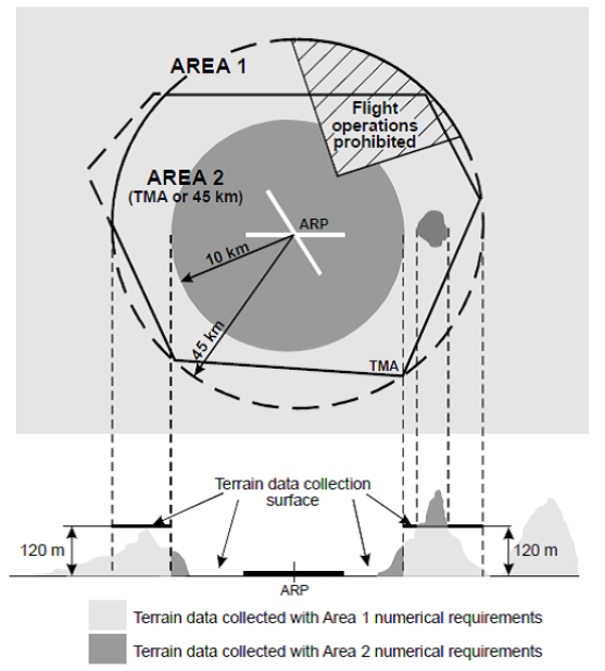
Figure 1 - Terrain data collection surfaces — Area 1 and Area 2
(1) Within the area covered by a 10-km radius from the ARP, terrain data should comply with the Area 2 numerical requirements;
(2) In the area between 10 km and the TMA boundary or 45-km radius (whichever is smaller), data on terrain that penetrates the horizontal plane 120 m above the lowest runway elevation, should comply with the Area 2 numerical requirements;
(3) In the area between 10 km and the TMA boundary or 45-km radius (whichever is smaller), data on terrain that does not penetrate the horizontal plane 120 m above the lowest runway elevation, should comply with the Area 1 numerical requirements;
(4) In those portions of Area 2 where flight operations are prohibited due to very high terrain or other local restrictions and/or regulations, terrain data should comply with the Area 1 numerical requirements.
(c) A graphical representation of the obstacle data collection surfaces for Areas 1 and 2 is shown in the following figure:
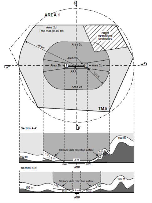
Figure 2 - Obstacle data collection surfaces — Area 1 and Area 2
(1) Obstacle data should be collected and recorded in accordance with the Area 2 numerical requirements;
(i) The Area 2a obstacle collection surface should have a height of 3 m above the nearest runway elevation measured along the runway centre line, and for those portions related to a clearway, if one exists, at the elevation of the nearest runway end;
(ii) The Area 2b obstacle collection surface has an 1.2 % slope extending from the ends of Area 2a at the elevation of the runway end in the direction of departure, with a length of 10 km and a splay of 15 % to each side;
(iii) The Area 2c collection surface has an 1.2 % slope extending outside Area 2a and Area 2b at a distance of not more than 10 km from the boundary of Area 2a. The initial elevation of Area 2c should be the elevation of the point of Area 2a at which it commences; and
(iv) The Area 2d obstacle collection surface has a height of 100 m above ground.
(2) In those portions of Area 2 where flight operations are prohibited due to very high terrain or other local restrictions and/or regulations, obstacle data should be collected and recorded in accordance with the Area 1 requirements;
(3) Data on every obstacle within Area 1 whose height above the ground is 100 m or higher should be collected and recorded in the database in accordance with the Area 1 numerical requirements specified in Table 2.
(d) A graphical representation of the terrain and obstacle data collection surfaces for Area 3 is shown in the following figure:
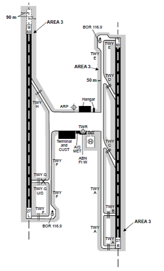
Figure 3 - Terrain and obstacle data collection surface — Area 3
(1) The data collection surface for terrain and obstacles extends a half metre (0.5 m) above the horizontal plane passing through the nearest point on the aerodrome movement area;
(2) Terrain and obstacle data in Area 3 should comply with the numerical requirements specified in Tables 1 and 2, respectively;
(e) A graphical representation of the obstacle data collection surfaces for Areas 4 is shown in the following figure:
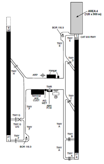
Figure 4 - Terrain and obstacle data collection surface — Area 4
(1) Terrain data in Area 4 should comply with the numerical requirements specified in Table 1;
(2) The horizontal extent of Area 2 covers Area 4. More detailed obstacle data may be collected in Area 4 in accordance with Area 4 numerical requirements for obstacle data specified in Table 2.
(3) Where the terrain at a distance greater than 900 m (3000 ft) from the runway threshold is mountainous or otherwise significant, the length of Area 4 should be extended to a distance not exceeding 2000 m (6500 ft) from the runway threshold.
|
|
Area 1 |
Area 2 |
Area 3 |
Area 4 |
|
Post spacing |
3 arc seconds (approx. 90 m) |
1 arc seconds (approx. 30 m) |
0.6 arc seconds (approx. 20 m) |
0.3 arc seconds (approx. 9 m) |
|
Vertical accuracy |
30 m |
3 m |
0.5 m |
1 m |
|
Vertical resolution |
1 m |
0.1 m |
0.01 m |
0.1 m |
|
Horizontal accuracy |
50 m |
5 m |
0.5 m |
2.5 m |
|
Confidence level |
90 % |
90 % |
90 % |
90 % |
|
Data classification Integrity level |
Routine |
Essential |
Essential |
Essential |
|
Maintenance period |
as required |
as required |
as required |
as required |
Table 1 - Terrain data numerical requirements
|
|
Area 1 |
Area 2 |
Area 3 |
Area 4 |
|
Vertical accuracy |
30 m |
3 m |
0.5 m |
1 m |
|
Vertical resolution |
1 m |
0.1 m |
0.01 m |
0.1 m |
|
Horizontal accuracy |
50 m |
5 m |
0.5 m |
2.5 m |
|
Confidence level |
90 % |
90 % |
90 % |
90 % |
|
Data classification Integrity level |
Routine |
Essential |
Essential |
Essential |
|
Maintenance period |
as required |
as required |
as required |
as required |
Table 2 - Obstacle data numerical requirements
ADR.OPS.A.010 Data quality requirements
Delegated Regulation (EU) 2020/2148
The aerodrome operator shall have formal arrangements with the organisations with which it exchanges aeronautical data or aeronautical information and shall ensure the following:
(a) all data relevant to the aerodrome and available services is provided with the required quality; data quality requirements (DQRs) are complied with at data origination and maintained during data transmission;
(b) the accuracy of aeronautical data is as specified in the aeronautical data catalogue;
(c) the integrity of aeronautical data is maintained throughout the data process from origination to transmission, based on the integrity classification specified in the aeronautical data catalogue. In addition, procedures shall be put in place so that:
(1) for routine data, corruption is avoided throughout the processing of the data;
(2) for essential data, corruption does not occur at any stage of the entire process and additional processes are included, as needed, to address potential risks in the overall system architecture to ensure data integrity at that level;
(3) for critical data, corruption does not occur at any stage of the entire process and additional integrity assurance processes are included to fully mitigate the effects of faults identified by thorough analysis of the overall system architecture as potential data integrity risks;
(d) the resolution of the aeronautical data is commensurate with the actual data accuracy;
(e) the traceability of the aeronautical data;
(f) the timeliness of the aeronautical data, including any limits on the effective period;
(g) the completeness of the aeronautical data;
(h) the format of the delivered data meets the specified requirements.
AMC1 ADR.OPS.A.010 Data quality requirements
ED Decision 2021/003/R
GENERAL REQUIREMENTS
The aerodrome operator should implement the procedures to:
(a) monitor data relevant to the aerodrome and available services originating from the aerodrome operator, and promulgated by the relevant air traffic services providers;
(b) notify the relevant aeronautical information services, and air traffic services providers of any changes necessary to ensure correct and complete data relevant to the aerodrome, and available services.
AMC2 ADR.OPS.A.010 Data quality requirements
ED Decision 2021/003/R
FORMAL ARRANGEMENTS
(a) Organisations concerned
The aerodrome operator should have formal arrangements with public or private entities providing:
(1) air navigation services;
(2) services for the origination and provision of survey data;
(3) procedure design services;
(4) electronic terrain data; and
(5) electronic obstacle data,
with which it exchanges aeronautical data and/or aeronautical information.
(b) Content of formal arrangements
Such formal arrangements should include the following minimum content:
(1) aeronautical data to be provided;
(2) the quality requirements for each data item supplied according to the aeronautical data catalogue;
(3) the method(s) for demonstrating that the data provided conforms with the specified requirements;
(4) the action to be taken in the event of discovery of a data error, or inconsistency in any data provided;
(5) the following minimum criteria for notification of data changes:
(i) criteria for determining the timeliness of data provision based on the operational or safety significance of the change;
(ii) any prior notice of expected changes; and
(iii) the means to be adopted for notification;
(6) the party responsible for documenting data changes;
(7) data exchange details such as format or format change process;
(8) any limitations on the use of data;
(9) requirements for the production of data origination quality reports;
(10) metadata to be provided; and
(11) contingency requirements concerning the continuity of data provision.
GM1 ADR.OPS.A.010 Data quality requirements
ED Decision 2021/003/R
CONTRACTED ACTIVITIES
In case of contracted activities to external organisations for the origination of aeronautical data and aeronautical information, data origination requirements for such organisations are to be found in ATM/ANS.OR.085 of Annex III of Commission Implementing Regulation (EU) 2017/373.
GM2 ADR.OPS.A.010 Data quality requirements
ED Decision 2021/003/R
URGENT DISTRIBUTION OF AERONAUTICAL INFORMATION
The obligation to comply with the relevant provisions of ADR.OPS.A.010 (Data quality requirements) does not prevent the urgent distribution of aeronautical information necessary to ensure the safety of flight. It is recognised that, in this case, it is not always possible to comply with all the relevant provisions. However, it is also not possible to determine a priori in all cases where this exception may apply; hence this is dependent on a case-by-case individual assessment made by competent staff.
GM1 ADR.OPS.A.010(d) Data quality requirements
ED Decision 2021/003/R
RESOLUTION
(a) Stating that resolution needs to be commensurate with the actual accuracy means that digital data needs to have sufficient resolution to maintain accuracy. Typically, if an accuracy of 0.1 unit is needed, then a resolution of 0.01 or 0.001 units would enable a data chain to preserve the accuracy without any issue. A finer resolution could be misleading as one could assume that it supports a finer accuracy. This factor range of 10 to 100 between accuracy and resolution is applicable regardless of the units of measurements used.
(b) The resolution should be enough to capture the accuracy of the data.
GM1 ADR.OPS.A.010(e) Data quality requirements
ED Decision 2021/003/R
TRACEABILITY
Traceability is supported by maintaining the metadata.
ADR.OPS.A.015 Coordination between aerodrome operators and providers of aeronautical information services
Regulation (EU) No 139/2014
(a) To ensure that aeronautical information services providers obtain information to enable them to provide up-to-date pre-flight information and to meet the need for in-flight information, the aerodrome operator shall make arrangements to report to the relevant aeronautical information service providers, with a minimum of delay, the following:
(1) information on the aerodrome conditions, disabled aircraft removal, rescue and firefighting and visual approach slope indicator systems;
(2) the operational status of associated facilities, services and navigational aids at the aerodrome;
(3) any other information considered to be of operational significance.
(b) Before introducing changes to the air navigation system, the aerodrome operator shall take due account of the time needed by the relevant aeronautical information services for the preparation, production and issue of relevant material for promulgation.
AMC1 ADR.OPS.A.015 Coordination between aerodrome operators and providers of aeronautical information services
ED Decision 2014/012/R
REPOR TING
(a) The aerodrome operator should report on matters of operational significance or affecting aircraft and aerodrome operations in order to take appropriate action, particularly in respect of the following:
(1) construction or maintenance work;
(2) rough or broken surfaces on a runway, a taxiway, or an apron;
(3) snow, slush ice or frost on a runway, a taxiway, or an apron;
(4) water on a runway, a taxiway, or an apron;
(5) snow banks or drifts adjacent to a runway, a taxiway, or an apron;
(6) anti-icing or de-icing liquid chemicals, or other contaminants on a runway, a taxiway, or an apron;
(7) other temporary hazards, including parked aircraft;
(8) failure or irregular operation of part or all of the aerodrome visual aids; and
(9) failure of the normal or secondary power supply.
(b) A change in the level of protection normally available at an aerodrome for rescue and firefighting should be expressed in terms of the new category available at the aerodrome. When such a change has been corrected, the air traffic services provider and the aeronautical information services providers should be advised accordingly.
(c) The aerodrome operator should observe the predetermined, internationally agreed AIRAC effective dates in addition to 14-day postage time when submitting the raw information/data to aeronautical information services that affect charts and/or computer-based navigation systems which qualify to be notified by the aeronautical information regulation and control (AIRAC) system.
ADR.OPS.A.020 Common reference systems
Delegated Regulation (EU) 2020/2148
For the purpose of air navigation, the aerodrome operator shall use:
(a) the World Geodetic System – 1984 (WGS-84) as the horizontal reference system;
(b) the mean sea level (MSL) datum as the vertical reference system;
(c) the Gregorian calendar and coordinated universal time (UTC) as the temporal reference systems.
GM1 ADR.OPS.A.020(a) Common reference systems
ED Decision 2021/003/R
HORIZONTAL REFERENCE SYSTEM — WGS-84
(a) A reference system provides a definition of a coordinate system in terms of the position of an origin in space, the orientation of an orthogonal set of Cartesian axes, and a scale. A terrestrial reference system defines a spatial reference system in which positions of points anchored on the Earth’s solid surface have coordinates. Examples are: WGS-84, ITRS/European Terrestrial Reference System (ETRS) and national reference systems.
(b) WGS-84 defines, inter alia, a conventional terrestrial reference system, a reference frame and a reference ellipsoid. WGS-84 is currently the reference system ICAO requires for georeferencing aeronautical information.
(c) Further explanation and guidance may be found in Annex B (Horizontal reference systems) to EUROCONTROL Specifications for the Origination of Aeronautical Data, Volume 2: Guidance material (EUROCONTROL-SPEC-154, Edition 1.0 of 04/02/2013).
GM2 ADR.OPS.A.020(a) Common reference systems
ED Decision 2021/003/R
TEMPORARY NON-COMPLIANCE OF GEOGRAPHICAL CO-ORDINATES
In those particular cases where geographical co-ordinates have been transformed into WGS-84 coordinates by mathematical means and whose accuracy of original field work does not meet the applicable requirements contained in the aeronautical data catalogue, they should be identified until the time when they can be compliant.
AMC1 ADR.OPS.A.020(b) Common reference systems
ED Decision 2021/003/R
VERTICAL REFERENCE SYSTEM
(a) The aerodrome operator should use the Earth Gravitational Model — 1996 (EGM-96), as the global gravity model.
(b) When a geoid model other than the EGM-96 model is used, a description of the model used, including the parameters required for height transformation between the model and EGM-96, should be provided in the aeronautical information publication (AIP).
GM1 ADR.OPS.A.020(b) Common reference systems
ED Decision 2021/003/R
VERTICAL REFERENCE SYSTEM
Further explanation and guidance may be found in Annex C (Vertical reference systems) to EUROCONTROL Specifications for the Origination of Aeronautical Data, Volume 2 (EUROCONTROL‑SPEC-154, Edition 1.0 of 04/02/2013).
GM2 ADR.OPS.A.020(b) Common reference systems
ED Decision 2021/003/R
MEAN SEA LEVEL
(a) The geoid globally most closely approximates mean sea level (MSL). It is defined as the equipotential surface in the gravity field of the Earth, which coincides with the undisturbed MSL extended continuously through the continents.
(b) Gravity-related heights (elevations) are also referred to as ‘orthometric heights’, while distances of points above the ellipsoid are referred to as ‘ellipsoidal heights’.
(c) Global and local geoids differ in their origin: global geoids consider only the long- and middle‑wave part of the Earth’s gravity field, whilst local geoids also consider the short-wave part of the gravity field. Global geoids are used when consistent orthometric heights, over long distances (continent or earth surveying), are required. Currently, the world’s best global geoid model is EGM 200846. It was determined using satellite tracking, gravity anomalies and satellite altimetry. Its accuracy is in the range of ± 0.05 m (oceans) and ± 0.5 m (on land). This accuracy is higher in flat regions than in topographically mountainous terrain, such as the Alps.
(d) For local engineering applications and cadastre-surveying, global geoids are not as accurate as needed. For such applications, local geoid models are calculated. These can only be developed using local field measurements. They offer centimetre accuracy over several hundred kilometres, with a high resolution. Local geoids are not suitable for height comparison over large distances since they are based on different origins and reference heights (different equipotential levels).
GM1 ADR.OPS.A.020(c) Common reference system
ED Decision 2021/003/R
TEMPORAL REFERENCE SYSTEM
(a) A value in the time domain is a temporal position measured relative to a temporal reference system.
(b) ISO Standard 8601 specifies the use of the Gregorian calendar and 24-hour local or UTC for information interchange, while ISO Standard 19108 prescribes the Gregorian calendar and UTC as the primary temporal reference system for use with geographic information.
ADR.OPS.A.025 Data error detection and authentication
Delegated Regulation (EU) 2020/2148
When originating, processing or transmitting data to the aeronautical information service (AIS) provider, the aerodrome operator shall:
(a) ensure that digital data error detection techniques are used during the transmission and storage of aeronautical data, in order to support the applicable data integrity levels;
(b) ensure that the transfer of aeronautical data is subject to a suitable authentication process such that recipients are able to confirm that the data or information has been transmitted by an authorised source.
GM1 ADR.OPS.A.025 Data error detection and authentication
ED Decision 2021/003/R
DIGITAL DATA ERROR DETECTION TECHNIQUES
(a) Digital data error detection techniques can be used to detect errors during the transmission or storage of data. An example of a digital error detection technique is the use of cyclic redundancy checks (CRCs). Coding techniques can be effective regardless of the transmission media (e.g. computer disks, modem communication, or internet).
(b) Transmission of data via electronic/digital means (e.g. file transfer protocol (FTP) sites, web downloads, or email) may be subject to malicious attack that can corrupt the integrity of data for its intended use. Provision of means to mitigate the intentional corruption of digitally transmitted data may already exist within the organisational construct and operating procedures of participating entities.
(c) The objective of data security is to ensure that data is received from a known source and that there is no intentional corruption during processing and exchange of data.
(d) Records are maintained to show what data security provisions have been implemented.
(e) Provisions supporting this objective may include:
(1) implementation of technical data security measures to provide authentication and prevent intentional corruption during exchange of data (e.g. secure hashes, secure transmissions, digital signatures); and
(2) implementation of organisational data security measures to protect processing resources and prevent intentional corruption during processing of data.
GM2 ADR.OPS.A.025 Data error detection and authentication
ED Decision 2021/003/R
DATA ERROR PROCESSING
More explanation and guidance may be found in Appendix C (Guidance on compliance with data processing requirements) to EUROCAE ED-76A.
ADR.OPS.A.030 Aeronautical data catalogue
Delegated Regulation (EU) 2020/2148
When originating, processing or transmitting data to the AIS provider, the aerodrome operator shall ensure that the aeronautical data referred to in Appendix 1 to Annex III (Part-ATM/ANS.OR) to Commission Implementing Regulation (EU) 2017/37321 Commission Implementing Regulation (EU) 2017/373 of 1 March 2017 laying down common requirements for providers of air traffic management/air navigation services and other air traffic management network functions and their oversight, repealing Regulation (EC) No 482/2008, Implementing Regulations (EU) No 1034/2011, (EU) No 1035/2011 and (EU) 2016/1377 and amending Regulation (EU) No 677/2011 (OJ L 62, 8.3.2017, p. 1). conform to the data catalogue specifications.
GM1 ADR.OPS.A.030 Aeronautical Data Catalogue
ED Decision 2021/003/R
GENERAL
The aeronautical data catalogue presents the scope of data that can be collected and maintained by the aeronautical information services providers and provides a common terminology that can be used by data originators and service providers.
ADR.OPS.A.035 Data validation and verification
Delegated Regulation (EU) 2020/2148
When originating, processing or transmitting data to the AIS provider, the aerodrome operator shall ensure that validation and verification techniques are employed so that the aeronautical data meets the associated DQRs. In addition:
(a) the verification shall ensure that the aeronautical data is received without corruption and that the aeronautical data process does not introduce corruption;
(b) aeronautical data and aeronautical information entered manually shall be subject to independent verification to detect any errors that may have been introduced;
(c) when using aeronautical data to obtain or calculate new aeronautical data, the initial data shall be verified and validated, except when provided by an authoritative source.
AMC1 ADR.OPS.A.035 Data verification and validation
ED Decision 2021/003/R
VALIDATION AND VERIFICATION
(a) The processes implemented to carry out validation and verifications should define the means used to:
(1) verify received data and confirm that the data has been received without corruption;
(2) preserve data quality and ensure that stored data is protected from corruption; and
(3) confirm that originated data has not been corrupted prior to being stored.
(b) Those processes should define the:
(1) actions to be taken when data fails a verification or validation check; and
(2) tools required for the verification and validation process.
GM1 ADR.OPS.A.035 Data verification and validation
ED Decision 2021/003/R
VALIDATION AND VERIFICATION — GENERAL
(a) Validation
(1) Validation is the activity where a data element is checked as having a value that is fully applicable to the identity ascribed to the data element, or where a set of data elements are checked as being acceptable for their intended use.
(2) The application of validation techniques considers the entire aeronautical data chain. This includes the validation performed by prior data chain participants and any requirements levied on the data supplier.
(3) Examples of validation techniques include:
(i) Validation by application
One method of validation is to apply data under test conditions. In certain cases, this may not be practical. Validation by application is considered to be the most effective form of validation. For example, flight inspection of final approach segment data prior to publication can be used to ensure that the published data is acceptable.
(ii) Logical consistency
Logical consistency validates by comparing two different data sets or elements and identifying inconsistencies between values based on operative rules (e.g. business rules).
(iii) Semantic consistency
Semantic consistency validates by comparing data to an expected value or range of values for the data characteristics.
(iv) Validation by sampling
Validation by sampling evaluates a representative sample of data and applies statistical analysis to determine the confidence in the data quality.
(b) Verification
(1) Verification is a process for checking the integrity of a data element whereby the data element is compared to another source, either from a different process or from a different point in the same process. While verification cannot ensure that the data is correct, it can be effective to ensure that the data has not been corrupted by the data process.
(2) The application of verification techniques considers only the portion of the aeronautical data chain controlled by the organisation. Yet, verification techniques may be applied at multiple phases of the data processing chain.
(3) Examples of verification techniques include:
(i) Feedback
Feedback testing is the comparison between the output and input state of a data set.
(ii) Independent redundancy
Independent redundancy testing involves processing the same data through two or more independent processes and comparing the data output of each process.
(iii) Update comparison
Updated data can be compared to its previous version. This comparison can identify all data elements that have changed. The list of changed elements can then be compared to a similar list generated by the supplier. A problem can be detected if an element is identified as changed on one list and not on the other.
GM2 ADR.OPS.A.035 Data verification and validation
ED Decision 2021/003/R
VALIDATION AND VERIFICATION TECHNIQUES
Validation and verification techniques are employed throughout the data processing chain to ensure that the data meets the associated data quality requirements. More explanatory material may be found in Appendix C (Guidance on compliance with data processing requirements) to EUROCAE ED‑76A ‘Standards for Processing Aeronautical Data’.
ADR.OPS.A.040 Error handling requirements
Delegated Regulation (EU) 2020/2148
The aerodrome operator shall ensure that:
(a) errors identified during data origination and after data delivery are addressed, corrected or resolved;
(b) priority is given to managing errors in critical and essential aeronautical data.
GM1 ADR.OPS.A.040 Error handling requirements
ED Decision 2021/003/R
GENERAL
(a) The term ‘error’ is understood as being defective, degraded, lost, misplaced or corrupted data elements, or data elements not meeting stated quality requirements.
(b) Guidance on how to detect, identify, report and address/resolve aeronautical data errors may be found in Appendix C (Guidance on compliance with data processing requirements) to EUROCAE ED-76A ‘Standards for Processing Aeronautical Data’.
Delegated Regulation (EU) 2020/2148
The aerodrome operator shall ensure that metadata include, as a minimum:
(a) the identification of the organisations or entities performing any action of originating, transmitting or manipulating the aeronautical data;
(b) the action performed;
(c) the date and time the action was performed.
ADR.OPS.A.050 Data transmission
Delegated Regulation (EU) 2020/2148
The aerodrome operator shall ensure that aeronautical data is transmitted by electronic means.
ADR.OPS.A.055 Tools and software
Delegated Regulation (EU) 2020/2148
When originating, processing or transmitting aeronautical data to the AIS provider, the aerodrome operator shall ensure that tools and software used to support or automate aeronautical data processes perform their functions without adversely impacting the quality of the aeronautical data.
GM1 ADR.OPS.A.055 Tools and software
ED Decision 2021/003/R
SOFTWARE
(a) A means by which the requirement can be met, is through the verification of software applied to a known executable version of the software in its target operating environment.
(b) The verification of software is a process of ensuring that the software meets the requirements for the specified application or intended use of the aeronautical data and aeronautical information.
(c) The verification of software is an evaluation of the output of an aeronautical data and/or aeronautical information software development process to ensure correctness and consistency with respect to the inputs and applicable software standards, rules and conventions used in that process.
GM2 ADR.OPS.A.055 Tools and software
ED Decision 2021/003/R
TOOLS
Tools can be qualified meeting point 2.4.5 Aeronautical Data Tool Qualification of EUROCAE ED‑76A/RTCA DO-200B ‘Standards for Processing Aeronautical Data’, dated June 2015.
ADR.OPS.A.057 Origination of NOTAM
Delegated Regulation (EU) 2020/2148
(a) The aerodrome operator shall:
(1) establish and implement procedures in accordance with which it originates a NOTAM issued by the relevant aeronautical information services provider:
(i) that contains information on the establishment, condition, or change of any aeronautical facility, service, procedure or hazard, the timely knowledge of which is essential to personnel involved with flight operations;
(ii) that contains information of a temporary nature and of short duration or that concerns operationally significant permanent changes or temporary changes of long duration that are made at short notice, except for extensive text or graphics, or both;
(2) designate aerodrome personnel, who have successfully completed relevant training and demonstrated their competence, to originate NOTAM and provide relevant information to the aeronautical information service providers with which it has arrangements;
(3) ensure that all other aerodrome personnel whose duties involve the use of NOTAM have successfully completed relevant training and demonstrated their competence to do so.
(b) The aerodrome operator shall originate a NOTAM when it is necessary to provide the following information:
(1) establishment of, closure of, or significant changes in the operation of aerodromes or heliports or runways;
(2) establishment of, withdrawal of, or significant changes in the operation of the aerodrome services;
(3) establishment of, withdrawal of, or significant changes in the operational capability of radio navigation and air-ground communication services for which the aerodrome operator is responsible;
(4) unavailability of backup and secondary systems, having a direct operational impact;
(5) establishment of, withdrawal of, or significant changes to visual aids;
(6) interruption of, or return to operation of, major components of aerodrome lighting systems;
(7) establishment of, withdrawal of, or significant changes to procedures for air navigation services for which the aerodrome operator is responsible;
(8) occurrence or correction of major defects or impediments in the manoeuvring area;
(9) changes to, and limitations on, the availability of fuel, oil and oxygen;
(10) establishment of, withdrawal of, or return to, operation of hazard beacons marking obstacles to air navigation;
(11) planned laser emissions, laser displays and search lights in the aerodrome surroundings, if pilots’ night vision is likely to be impaired;
(12) erecting or removal of, or changes to, obstacles to air navigation in the takeoff, climb, missed approach, approach areas, as well as on the runway strip;
(13) changes in aerodrome or heliport rescue and firefighting category;
(14) presence of, removal of, or significant changes in, hazardous conditions due to snow, slush, ice, radioactive material, toxic chemicals, volcanic ash deposition or water on the movement area;
(15) presence of a runway or portion thereof which is slippery wet;
(16) presence of a runway which is not available due to runway marking works; or information about the time lag required for making the runway available, if the equipment used for such works can be removed, when necessary;
(17) presence of hazards that affect air navigation, including presence of wildlife, obstacles, displays and major events.
(c) For the purposes of point (b), the aerodrome operator shall ensure that:
(1) NOTAM is originated with sufficient lead time for the affected parties to take any required action, except in the case of unserviceability, release of radioactive material, toxic chemicals and other events that cannot be foreseen;
(2) a NOTAM notifying unserviceability of associated facilities, services and navigation aids at the aerodrome, provides an estimate of the unserviceability period or of the time at which restoration of service is expected;
(3) within three months from the issuance of a permanent NOTAM, the information contained in the NOTAM is included in the aeronautical information products affected;
(4) within three months from the issuance of a temporary NOTAM of long duration, the information contained in the NOTAM is included in an AIP supplement;
(5) when a NOTAM with an estimated end of validity unexpectedly exceeds the three-month period, a replacement NOTAM is originated unless the condition is expected to last for a further period of more than three months; in that case, the aerodrome operator shall ensure that the information is published in an AIP supplement.
(d) In addition, the aerodrome operator shall ensure that:
(1) except as provided for in point (d)(4), each NOTAM it originates contains the applicable information in the order shown in the NOTAM Format set out in Appendix 1 to this Annex;
(2) NOTAM text is composed of the significations or uniform abbreviated phraseology assigned to the ICAO NOTAM Code, complemented by ICAO abbreviations, indicators, identifiers, designators, call signs, frequencies, figures and plain language;
(3) a NOTAM is originated in the English language or the national language, as agreed with the relevant aeronautical information services provider;
(4) information concerning snow, slush, ice, frost, standing water or water associated with snow, slush, ice or frost on the movement area is disseminated by means of SNOWTAM and contains the information in the order shown in the SNOWTAM Format set out in Appendix 2 to this Annex;
(5) when an error has occurred in a NOTAM, a NOTAM with a new number is originated to replace the erroneous NOTAM or the erroneous NOTAM is cancelled and a new NOTAM is originated;
(6) when a NOTAM is originated to cancel or replace a previous NOTAM:
(a) the series and number/year of the previous NOTAM are indicated;
(b) the Location Indicators and subject of both NOTAM are the same;
(7) only one NOTAM is cancelled or replaced by a new NOTAM;
(8) each originated NOTAM deals with only one subject and one condition of the subject;
(9) each originated NOTAM is as brief as possible and compiled so that its meaning is clear without the need to refer to another document;
(10) an originated NOTAM containing permanent or temporary information of long duration includes appropriate references to the AIP or AIP supplement;
(11) the ICAO Location Indicator included in the text of an originated NOTAM for the aerodrome is the one contained in the Location Indicators. A curtailed form of such indicators shall not be used.
(e) The aerodrome operator shall, following the publication of a NOTAM that it has originated, review its content to ensure its accuracy, and ensure the dissemination of the information to all relevant aerodrome personnel and organisations at the aerodrome.
(f) The aerodrome operator shall maintain records:
(1) of the NOTAM it originated and those that were issued;
(2) regarding the implementation of points (a)(2) and (3).
AMC1 ADR.OPS.A.057(a)(1) Origination of NOTAM
ED Decision 2021/003/R
GENERAL
The procedures should as a minimum:
(a) define the ways and means that the aerodrome operator may use to request the issuance of a NOTAM, in accordance with the arrangements that the aerodrome operator has with the aeronautical information service (AIS) provider(s). The procedures should clearly indicate the names of the aerodrome operator’s personnel that have the authority to originate a NOTAM, and which should be included in the arrangements with the AIS provider.
(b) contain instructions regarding the:
(1) cases when a NOTAM should be originated by the aerodrome operator;
(2) cases when a NOTAM should not be originated by the aerodrome operator; and
(3) completion of the NOTAM form (including the use of relevant electronic applications, if applicable) by the personnel designated by the aerodrome operator as NOTAM originators; and
(c) specify the cases in which coordination with the Competent Authority is needed prior to the origination of the NOTAM, and the way to inform the Competent Authority about the issuance of a NOTAM.
AMC1 ADR.OPS.A.057(a)(2);(3) Origination of NOTAM
ED Decision 2021/003/R
INITIAL TRAINING FOR AERODROME PERSONNEL INVOLVED IN NOTAM ORIGINATION AND OTHER AERODROME PERSONNEL
(a) The theoretical part of the training of a person to be designated as a NOTAM originator should, as a minimum, cover the following areas:
(1) regulatory framework governing NOTAM origination and issuance, and its relationship with other aeronautical data products, including:
(i) cases when the origination of a NOTAM is required;
(ii) cases when a NOTAM should not be originated.
(2) NOTAM form completion, including word abbreviations and phrase contractions applicable to NOTAMs;
(3) NOTAM types and understanding of NOTAM;
(4) use of electronic applications for initiating a NOTAM (if applicable); and
(5) aerodrome procedures for origination and internal dissemination of a NOTAM.
The theoretical training should be followed by an assessment of the trainees (see AMC1 ADR.OR.D.017(e).
(b) Following the successful completion of the theoretical training, the practical part of the training should, as a minimum, include familiarisation with the origination of NOTAM and implementation of the relevant aerodrome operating procedures for the persons to be designated as NOTAM originators. Upon completion of the practical training, and the successful competency assessment of the trainee in practical terms, the person may be designated as a NOTAM originator.
(c) For other aerodrome personnel, whose duties require only the understanding of a NOTAM, the theoretical part of the training should be adjusted to their needs and need not include (a)(4) and (a)(5) above, while the practical training should include practical examples to assess the level of their understanding. Both the theoretical and the practical training should be followed by an assessment of the person concerned (see AMC1 ADR.OR.D.017(e)).
GM1 ADR.OPS.A.057(a)(2);(3) Origination of NOTAM
ED Decision 2021/003/R
RECURRENT, REFRESHER AND CONTINUATION TRAINING
ADR.OR.D.017 point (f) regulates the provision of training following the completion of the initial training, as part of the aerodrome operator’s training programme. For the process that needs to be followed to ensure the continued competence of the personnel involved in NOTAM origination and use, see ADR.OR.D.017(f) and AMC1 ADR.OR.D.017(f).
GM1 ADR.OPS.A.057(b) Origination of NOTAM
ED Decision 2021/003/R
NON-ORIGINATION OF NOTAM
Promulgation of information through NOTAM is required under certain circumstances. In such cases, the responsible organisation (e.g. Competent Authority, aerodrome operator, air traffic services provider, etc.) originates a NOTAM, which is finally issued by the AIS provider. ADR.OPS.A.057 defines the responsibilities of the aerodrome operator with respect to the NOTAM origination process, while its point (b) requires the origination of a NOTAM by the aerodrome operator in the cases prescribed in it.
On the other hand, for a variety of reasons (e.g. prevention of information overflow), not all kinds of information are eligible for promulgation through NOTAM. To this end, Regulation (EU) 2017/373, which applies to AIS providers, prescribes in AIS.TR.330 the cases where the AIS provider shall (or shall not) issue a NOTAM.
This means that there are cases in which, even if an aerodrome operator originates a NOTAM to promulgate information, the NOTAM will not be finally issued by the AIS provider if this information is not allowed to be promulgated by NOTAM as per AIS.TR.330. To avoid such situations, the aerodrome operator needs to:
(a) ensure that the relevant aerodrome operator’s personnel are adequately trained in the relevant regulatory framework regarding both the origination and issuance of NOTAM;
(b) develop robust procedures regarding NOTAM origination by its personnel; and
(c) maintain close cooperation with the relevant AIS provider.
The following are example cases where the aerodrome operator will not originate a NOTAM:
(a) routine maintenance work on aprons and taxiways that does not affect the safe movement of aircraft;
(b) temporary obstructions in the vicinity of aerodromes/heliports that do not affect the safe operation of aircraft;
(c) partial failure of aerodrome/heliport lighting facilities where such a failure does not directly affect aircraft operations;
(d) partial temporary failure of air-ground communications when suitable alternative frequencies are available and are operative;
(e) lack of apron marshalling services, road traffic closures, limitations and control;
(f) unserviceability of location, destination or other instruction signs on the aerodrome movement area;
(g) training activities performed by ground units;
(h) unavailability of backup and secondary systems if these systems do not have an operational impact;
(i) limitations to aerodrome facilities or general services with no operational impact;
(j) announcements or warnings about possible/potential limitations with no operational impact;
(k) general reminders on already published information;
(l) availability of equipment for ground units, without information on the operational impact on airspace and facility users;
(m) information about laser emissions with no operational impact and about fireworks below the minimum flying heights;
(n) closure of parts of the movement area in connection with locally coordinated, planned work of duration of less than 1 hour;
(o) closure, changes, unavailability in the operation of aerodrome(s)/heliport(s) other than in the aerodrome(s)/heliport(s) operation hours; and
(p) other non-operational information of a similar temporary nature.
Information which relates to an aerodrome and its vicinity and which does not affect its operational status may be distributed locally during pre-flight or in-flight briefing or other local contact with flight crews. Thus, in case of need, the aerodrome operator may disseminate such type of information through the AIS provider it has arrangements with.
GM2 ADR.OPS.A.057(b) Origination of NOTAM
ED Decision 2021/003/R
PRESENCE OF WILDLIFE
The permanent presence of wildlife is to be contained in the AIP, whereas the notification of hazardous wildlife activity at short notice needs to be promulgated by NOTAM.
When originating such a NOTAM, specific bird-related abbreviations should be avoided to facilitate readability and to prevent queries.
GM1 ADR.OPS.A.057(d)(1) Origination of NOTAM
ED Decision 2021/003/R
NOTAM FORMAT
Information on the completion of a NOTAM format may be found in Chapter 6 of ICAO Doc 8126 ‘Aeronautical Information Services Manual’.
Information on the ICAO NOTAM code and abbreviations to be used may be found in ICAO Doc 8400 ‘Procedures for Air Navigation Services - ICAO Abbreviations and Codes’ (PANS ABC).
GM1 ADR.OPS.A.057(d)(4) Origination of NOTAM
ED Decision 2022/016/R
SNOWTAM FORMAT
The way to complete correctly a SNOWTAM format when initiating a SNOWTAM is indicated below.
1. General
(a) When reporting on more than one runway, repeat Items B to H (aeroplane performance calculation section).
(b) The letters used to indicate items are only used for reference purposes and should not be included in the messages. The letters M (mandatory), C (conditional) and O (optional) mark the usage and information and should be included as explained below.
(c) Metric units should be used, and the unit of measurement shall not be reported.
(d) The maximum validity of SNOWTAM is 8 hours. A new SNOWTAM should be issued whenever a new RCR is received.
(e) A SNOWTAM cancels the previous SNOWTAM.
(f) The abbreviated heading ‘TTAAiiii CCCC MMYYGGgg (BBB)’ is included to facilitate the automatic processing of SNOWTAM messages in computer databanks. The explanation of these symbols is:
TT = data designator for SNOWTAM = SW;
AA = geographical designator for Member States, e.g. LF = FRANCE;
iiii = SNOWTAM serial number in a four-digit group;
CCCC = four-letter location indicator of the aerodrome to which the SNOWTAM refers;
MMYYGGgg = date/time of observation/measurement, whereby:
MM = month, e.g. January = 01, December = 12;
YY = day of the month;
GGgg = time in hours (GG) and minutes (gg) UTC;
(BBB) = optional group for:
Correction, in the case of an error, to a SNOWTAM message previously disseminated with the same serial number = COR.
Brackets in (BBB) are used to indicate that this group is optional.
When reporting on more than one runway and individual dates/times of observation/assessment are indicated by the repeated Item B, the latest date/time of observation/assessment is inserted in the abbreviated heading (MMYYGGgg).
(g) The text ‘SNOWTAM’ in the SNOWTAM Format and the SNOWTAM serial number in a four-digit group is separated by a space, e.g. SNOWTAM 0124.
(h) For readability purposes for the SNOWTAM message, a linefeed would be included after the SNOWTAM serial number, after Item A, and after the aeroplane performance calculation section.
(i) When reporting on more than one runway, repeat the information in the aeroplane performance calculation section from the date and time of assessment for each runway before the information in the situational awareness section.
(j) Mandatory information is:
(1) AERODROME LOCATION INDICATOR;
(2) DATE AND TIME OF ASSESSMENT;
(3) LOWER RUNWAY DESIGNATOR NUMBER;
(4) RUNWAY CONDITION CODE FOR EACH RUNWAY THIRD; and
(5) CONDITION DESCRIPTION FOR EACH RUNWAY THIRD (when RWYCC is reported 1‑5)
2. Aeroplane performance calculation section
Item A — Aerodrome location indicator (four-letter location indicator).
Item B — Date and time of assessment (eight-figure date/time group giving time of observation as month, day, hour and minute in UTC).
Item C — Lower runway designator number (nn[L] or nn[C] or nn[R]).
Only one runway designator should be inserted for each runway and always the lower number.
Item D — RWYCC for each runway third. Only one digit (0, 1, 2, 3, 4, 5 or 6) is inserted for each runway third, separated by an oblique stroke (n/n/n).
Item E — Per cent coverage for each runway third. When provided, insert 25, 50, 75 or 100 for each runway third, separated by an oblique stroke ([n]nn/[n]nn/[n]nn).
This information is provided only when there is a condition description for each runway third (Item G) that has been reported other than ‘DRY’.
When the conditions are not reported, this is signified by the insertion of ‘NR’ for the appropriate runway third(s).
Item F — Depth of loose contaminant for each runway third. When provided, insert in millimetres for each runway third, separated by an oblique stroke (nn/nn/nn or nnn/nnn/nnn).
This information is only provided for the following contamination types:
— standing water, value to be reported 04, then assessed value. Significant changes 3 mm;
— slush, value to be reported 03, then assessed value. Significant changes 3 mm;
— wet snow, value to be reported 03, then assessed value. Significant changes 5 mm; and
— dry snow, value to be reported 03, then assessed value. Significant changes 20 mm.
— When the conditions are not reported, this is signified by the insertion of ‘NR’ for the appropriate runway third(s).
Item G — Condition description for each runway third. Any of the following condition descriptions for each runway third, separated by an oblique stroke, is inserted.
COMPACTED SNOW
DRY SNOW
DRY SNOW ON TOP OF COMPACTED SNOW
DRY SNOW ON TOP OF ICE
FROST
ICE
SLIPPERY WET
SLUSH
SPECIALLY PREPARED WINTER RUNWAY
STANDING WATER
WATER ON TOP OF COMPACTED SNOW
WET
WET ICE
WET SNOW
WET SNOW ON TOP OF COMPACTED SNOW
WET SNOW ON TOP OF ICE
DRY (only reported when there is no contaminant)
When the conditions are not reported, this is signified by the insertion of ‘NR’ for the appropriate runway third(s).
Item H — Width of runway to which the RWYCCs apply. The width in metres if less than the published runway width is inserted.
3. Situational awareness section
Elements in the situational awareness section end with a full stop.
Elements in the situational awareness section for which no information exists, or where the conditional circumstances for publication are not fulfilled, are left out completely.
Item I — Reduced runway length. The applicable runway designator and available length in metres is inserted (e.g. RWY nn [L] or nn [C] or nn [R] REDUCED TO [n]nnn).
This information is conditional when a NOTAM has been published with a new set of declared distances.
Item J — Drifting snow on the runway. When reported, the lower runway designator is inserted with a space ‘DRIFTING SNOW’ (RWY nn or RWY nn[L] or nn[C] or nn[R] DRIFTING SNOW).
Item K — Loose sand on the runway. When loose sand is reported on the runway, the lower runway designator is inserted with a space ‘LOOSE SAND’ (RWY nn or RWY nn[L] or nn[C] or nn[R] LOOSE SAND).
Item L — Chemical treatment on the runway. When application of chemical treatment has been reported, the lower runway designator is inserted with a space ‘CHEMICALLY TREATED’ (RWY nn or RWY nn[L] or nn[C] or nn[R] CHEMICALLY TREATED).
Item M — Snowbanks on the runway. When snowbanks are reported present on the runway, the lower runway designator is inserted with a space ‘SNOWBANK’ and with a space left ‘L’ or right ‘R’ or both sides ‘LR’, followed by the distance in metres from centre line separated by a space ‘FM CL’ (RWY nn or RWY nn[L] or nn[C] or nn[R] SNOWBANK Lnn or Rnn or LRnn FM CL).
Item N — Snowbanks on a taxiway. When snowbanks are present on taxiway(s), the taxiway(s) designator(s) is (are) inserted with a space ‘SNOWBANKS’ (TWY [nn]n or TWYS [nn]n/[nn]n/[nn]n/… or ALL TWYS SNOWBANKS).
Item O — Snowbanks adjacent to the runway. When snowbanks are reported present, penetrating the height profile in the aerodrome snow plan, the lower runway designator and ‘ADJ SNOWBANKS’ are inserted (RWY nn or RWY nn[L] or nn[C] or nn[R] ADJ SNOWBANKS).
Item P — Taxiway conditions. When taxiway conditions are reported slippery or poor, the taxiway designator followed by a space ‘POOR’ is inserted (TWY [n or nn] POOR or TWYS [n or nn]/[n or nn]/… POOR or ALL TWYS POOR).
Item R — Apron conditions. When apron conditions are reported slippery or poor, the apron designator followed by a space ‘POOR’ is inserted (APRON [nnnn] POOR or APRONS [nnnn]/[nnnn]/… POOR or ALL APRONS POOR).
Item S — NR (not reported).
Item T — Plain-language remarks.
GM2 ADR.OPS.A.057(d)(4) Origination of NOTAM
ED Decision 2021/003/R
SNOWTAM FORMAT
Below are four examples of completed SNOWTAMs.
Example SNOWTAM 1
GG EADBZQZX EADNZQZX EADSZQZX
170100 EADDYNYX
SWEA0149 EADD 02170055
(SNOWTAM 0149
EADD
02170055 09L 5/5/5 100/100/100 NR/NR/03 WET/WET/WET SNOW)
Example SNOWTAM 2
GG EADBZQZX EADNZQZX EADSZQZX
170140 EADDYNYX
SWEA0150 EADD 02170135
(SNOWTAM 0150
EADD
02170055 09L 5/5/5 100/100/100 NR/NR/03 WET/WET/WET SNOW
02170135 09R 5/2/2 100/50/75 NR/06/06 WET/SLUSH/SLUSH)
Example SNOWTAM 3
GG EADBZQZX EADNZQZX EADSZQZX
170229 EADDYNYX
SWEA0151 EADD 02170225
(SNOWTAM 0151
EADD
02170055 09L 5/5/5 100/100/100 NR/NR/03 WET/WET/WET SNOW
02170135 09R 5/2/2 100/50/75 NR/06/06 WET/SLUSH/SLUSH
02170225 09C 2/3/3 75/100/100 06/12/12 SLUSH/WET SNOW/WET SNOW
RWY 09L SNOWBANK R20 FM CL. RWY 09R ADJ SNOWBANKS. TWY B POOR. APRON NORTH POOR)
Example SNOWTAM 4
GG EADBZQZX EADNZQZX EADSZQZX
170350 EADDYNYX
SWEA0152 EADD 02170345
(SNOWTAM 0152
EADD
02170345 09L 5/5/5 100/100/100 NR/NR/03 WET/WET/SLUSH
02170134 09R 5/2/2 100/50/75 NR/06/06 WET/SLUSH/SLUSH
02170225 09C 2/3/3 75/100/100 06/12/12 SLUSH/WET SNOW/WET SNOW
DRIFTING SNOW. RWY 09L LOOSE SAND. RWY 09R CHEMICALLY TREATED. RWY 09C CHEMICALLY TREATED.)
ADR.OPS.A.060 Reporting of surface contaminants
Delegated Regulation (EU) 2020/2148
The aerodrome operator shall report to the aeronautical information services and air traffic services units on matters of operational significance affecting aircraft and aerodrome operations on the movement area, particularly in respect of the presence of the following:
(a) water;
(b) snow;
(c) slush;
(d) ice;
(e) frost;
(f) anti-icing or de-icing liquid chemicals or other contaminants;
(g) snowbanks or drifts.
ADR.OPS.A.065 Reporting of the runway surface condition
Delegated Regulation (EU) 2020/2148
(a) The aerodrome operator shall report the runway surface condition over each third of the runway using a runway condition report (RCR). The report shall include a runway condition code (RWYCC) using numbers 0 to 6, the contaminant coverage and depth, and a description using the following terms:
(1) COMPACTED SNOW;
(2) DRY;
(3) DRY SNOW;
(4) DRY SNOW ON TOP OF COMPACTED SNOW;
(5) DRY SNOW ON TOP OF ICE;
(6) FROST;
(7) ICE;
(8) SLIPPERY WET;
(9) SLUSH;
(10) SPECIALLY PREPARED WINTER RUNWAY;
(11) STANDING WATER;
(12) WATER ON TOP OF COMPACTED SNOW;
(13) WET;
(14) WET ICE;
(15) WET SNOW;
(16) WET SNOW ON TOP OF COMPACTED SNOW;
(17) WET SNOW ON TOP OF ICE;
(18) CHEMICALLY TREATED;
(19) LOOSE SAND.
(b) Reporting shall commence when a significant change in runway surface condition occurs due to water, snow, slush, ice or frost.
(c) Reporting of the runway surface condition shall continue to reflect significant changes until the runway is no longer contaminated. When that situation occurs, the aerodrome operator shall issue an RCR that states that the runway is wet or dry as appropriate.
(d) Friction measurements shall not be reported.
(e) When a paved runway or portion thereof is slippery wet, the aerodrome operator shall make such information available to the relevant aerodrome users. That shall be done by originating a NOTAM and shall describe the location of the affected portion.
AMC1 ADR.OPS.A.065(a) Reporting of the runway surface condition
ED Decision 2021/003/R
REPORTING
The aerodrome operator should disseminate an RCR through the aeronautical information services and air traffic services, when the runway is wholly or partly contaminated by standing water, snow, slush, ice or frost, or is wet associated with the clearing or treatment of snow, slush, ice or frost. When the runway is wet, not associated with the presence of standing water, snow, slush, ice or frost, the assessed information should be disseminated using the RCR through the air traffic service.
AMC2 ADR.OPS.A.065(a) Reporting of the runway surface condition
ED Decision 2021/003/R
RUNWAY CONDITION REPORT
(a) The RCR should consist of the:
(1) aeroplane performance calculation section; and
(2) situational awareness section.
(b) The information should be included in an information string in the following order:
(1) aeroplane performance calculation section:
(i) aerodrome location indicator;
(ii) date and time of assessment;
(iii) lower runway designation number;
(iv) RWYCC for each runway third;
(v) per cent coverage contaminant for each runway third;
(vi) depth of loose contaminant for each runway third;
(vii) condition description for each runway third; and
(viii) width of runway to which the RWYCCs apply if less than the published width.
(2) Situational awareness section:
(i) reduced runway length;
(ii) drifting snow on the runway;
(iii) loose sand on the runway;
(iv) chemical treatment on the runway;
(v) snowbanks on the runway;
(vi) snowbanks on the taxiway;
(vii) snowbanks adjacent to the runway;
(viii) taxiway conditions;
(ix) apron conditions; and
(x) plain-language remarks.
GM1 ADR.OPS.A.065(a) Reporting of the runway surface condition
ED Decision 2021/003/R
GENERAL
(a) Assessing and reporting the condition of the movement area and related facilities is necessary in order to provide the flight crew with the information needed for safe operation of the aeroplane. The RCR is used for reporting assessed conditions through the issuance of SNOWTAM, when necessary.
(b) Generally, movement areas are exposed to a multitude of climatic conditions and consequently there is a significant difference in the conditions to be reported. The RCR describes a basic structure applicable for all these climatic variations. Assessing the runway surface condition relies on a great variety of techniques and no single solution can apply to every situation.
(c) The philosophy of the RCR is that the aerodrome operator assesses the runway surface condition whenever water, snow, slush, ice or frost are present on an operational runway. From this assessment, a RWYCC and a description of the runway surface are reported, which can be used by the flight crew for aeroplane performance calculations. This format, based on the type, depth and coverage of contaminants, is the best assessment of the runway surface condition by the aerodrome operator; however, all other pertinent information is taken into consideration and kept up to date, and changes in conditions are reported without delay.
(d) The RWYCC reflects the runway braking capability as a function of the surface conditions. With this information, the flight crew can derive, from the performance information provided by the aeroplane manufacturer, the necessary stopping distance of an aircraft on the approach under the prevailing conditions.
GM2 ADR.OPS.A.065(a) Reporting of the runway surface condition
ED Decision 2021/003/R
RUNWAY CONDITION REPORT
AEROPLANE PERFORMANCE CALCULATION SECTION
(a) The aeroplane performance calculation section is a string of grouped information, separated by a space ‘ ’ ending with a return and a two-line feed ‘<<≡’, in order to distinguish the aeroplane performance calculation section from the following situational awareness section or the following aeroplane performance calculation section of another runway.
(b) The information to be included in this section consists of the following:
(1) Aerodrome location indicator: a four-letter ICAO location indicator in accordance with ICAO Doc 7910 ‘Location Indicators’.
This information is mandatory.
Format: nnnn
(2) Date and time of the assessment: date and time (UTC) when the assessment was performed.
This information is mandatory.
Format: MMDDhhmm
(3) Lower runway designation number: a two- or three-character number identifying the runway for which the assessment is carried out and reported.
This information is mandatory.
Format: nn[L] or nn[C] or nn[R]
(4) Runway condition code for each runway third: a one-digit number identifying the RWYCC assessed for each runway third. The codes are reported in a three-character group separated by a ‘/’ for each third. The direction for listing the runway thirds is the direction as seen from the lower designation number.
This information is mandatory.
When transmitting information on the runway surface condition by air traffic services to flight crews, the sections are, however, referred to as the first, second or third part of the runway. The first part always means the first third of the runway as seen in the direction of landing or take-off as illustrated in Figures 1 and 2.
Format: n/n/n
Example: 5/5/2
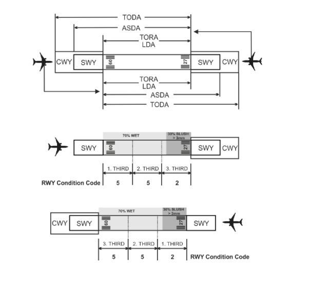 Figure 1: Reporting of RWYCC
from air traffic services to flight crew for runway thirds
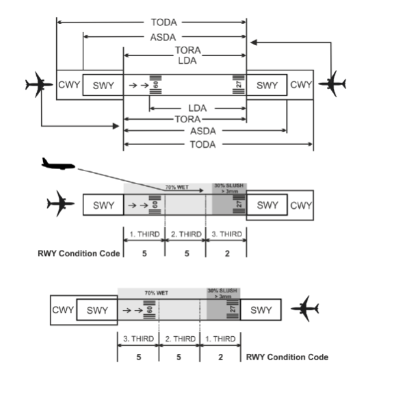
Figure 2: Reporting of RWYCC
for runway thirds from air traffic services to flight crew on a runway with displaced threshold
(5) Per cent coverage contaminant for each runway third: a number identifying the percentage coverage. The percentages are to be reported in an up-to-nine character group separated by a ‘/’ for each runway third. The assessment is based upon an even distribution within the runway thirds using Table 1.
This information is conditional. It is not reported for any runway third that is dry or covered with less than 10 per cent.
Format: [n]nn/[n]nn/[n]nn
Example: 25/50/100
In case of uneven distribution of the contaminants, additional information is given in the plain-language remark part of the situational awareness section of the RCR. Where possible, a standardised text is used.
When no information is to be reported, ‘NR’ is inserted at the relevant position of the message, to indicate to the user that no information exists.
(6) Depth of loose contaminant: dry snow, wet snow, slush or standing water for each runway third: a two- or three-digit number representing the assessed depth (mm) of the contaminant for each runway third. The depth is reported in a six-to nine-character group separated by a ‘/’ for each runway third as defined in Table 2 of AMC1 ADR.OPS.A.065(b);(c). The assessment is based upon an even distribution within the runway thirds following an assessment. If measurements are included as part of the assessment process, the reported values are still reported as assessed depths.
This information is conditional. It is reported only for DRY SNOW, WET SNOW, SLUSH and STANDING WATER.
Format: [n]nn/[n]nn/[n]nn
(7) Condition description for each runway third: to be reported in capital letters using the terms specified in ADR.OPS.A.065 point (a). The condition types are separated by an oblique stroke ‘/’.
This information is mandatory.
Format: nnnn/nnnn/nnnn
(8) Width of runway to which the RWYCCs apply if less than the published width: two-digit number representing the width of cleared runway in metres.
This information is conditional.
Format: nn
If the cleared runway width is not symmetrical along the centre line, additional information is given in the plain-language remark part of the situational awareness section of the RCR.
SITUATIONAL AWARENESS SECTION
(a) All individual messages in the situational awareness section end with a full-stop sign, in order to distinguish the message from subsequent message(s).
(b) The information to be included in this section consists of the following:
(1) Reduced runway length
The information is conditional when a NOTAM has been published with a new set of declared distances affecting the landing distance available (LDA).
Format: Standardised fixed text – RWY nn [L] or nn [C] or nn [R] LDA REDUCED TO [n]nnn
(2) Drifting snow on the runway
This information is conditional.
Format: Standardised fixed text – RWY nn [L] or nn [C] or nn[R] DRIFTING SNOW
(3) Loose sand on the runway
This information is conditional.
Format: RWY nn[L] or nn[C] or nn[R] LOOSE SAND
(4) Chemical treatment on the runway
This information is conditional.
Format: RWY nn[L] or nn[C] or nn[R] CHEMICALLY TREATED
(5) Snowbanks on the runway
This information is conditional.
Left or right distance in metres from centre line.
Format: RWY nn[L] or nn[C] or nn[R] SNOWBANK Lnn or Rnn or LRnn FM CL
(6) Snowbanks on taxiway
This information is conditional.
Format: TWY [nn]n or TWYS [nn]n/[nn]n/[nn]n/… or ALL TWYS SNOWBANKS
(7) Snowbanks adjacent to the runway penetrating level/profile set in the aerodrome snow plan
This information is conditional.
Format: RWY nn[L] or nn[C] or nn[R] ADJ SNOWBANKS
(8) Taxiway conditions
This information is optional.
Format: TWY [nn]n POOR or TWYS[nn]n/[nn]n/… POOR or ALL TWYS POOR
(9) Apron conditions
This information is conditional.
Format: APRON [nnnn] POOR or APRONS[nnnn]/[nnnn]/… POOR or ALL APRONS POOR
(10) Plain-language remarks using only allowable characters in capital letters
Where possible, standardised text is used.
This information is optional except for the conditional information ‘UPGRADED’ or ‘DOWNGRADED’ used whenever the assessed RWYCC differs from what follows directly from the runway condition assessment matrix (RCAM). When present, this information is to be the first piece of information of the plain language remarks in order to ease readability and to recognise its importance as part of the situational awareness prior to aeroplane performance calculations.
Format: Combination of allowable characters where use of full stop ‘.’ marks the end of the message.
Allowable characters:
A B C D E F G H I J K LM N O P Q R S T U V W X Y Z
0 1 2 3 4 5 6 7 8 9
/ [oblique stroke] ‘.’ [period]’ ‘ [space]
If ICE, SNOW or SNOW ON ICE affects only the runway edge, the following text may be used:
RWY nn[L] or nn[C] or nn[R] ICE or SNOW or SNOW ON ICE Lnn or Rnn or LRnn FM EDGE
GM3 ADR.OPS.A.065(a) Reporting of the runway surface condition
ED Decision 2021/003/R
COMPLETE INFORMATION STRING
An example of a complete information string prepared for dissemination is as follows:
COM header and abbreviated header] (Completed by AIS)
GG EADBZQZX EADNZQZX EADSZQZX
070645 EADDYNYX
SWEA0151 EADD 02170055
SNOWTAM 0151
[Aeroplane performance calculation section]
EADD 02170055 09L 5/5/5 100/100/100 NR/NR/NR WET/WET/WET
EADD 02170135 09R 5/2/2 100/50/75 NR/06/06 WET/SLUSH/SLUSH
EADD 02170225 09C 2/3/3 75/100/100 06/12/12 SLUSH/WET SNOW/WET SNOW
[Situational awareness section]
RWY 09L SNOWBANK R20 FM CL. RWY 09R ADJ SNOWBANKS. TWY B POOR. APRON NORTH POOR.
GM4 ADR.OPS.A.065(a) Reporting of the runway surface condition
ED Decision 2021/003/R
REPORTING BY AERODROMES WITH MULTIPLE RUNWAYS
On aerodromes with multiple runways, SNOWTAM includes all the runways, in case that at least one runway is contaminated. This improves pilots’ situational awareness and support their decision on the selection of the landing/take-off runway.
GM1 ADR.OPS.A.065(a)(18);(19) Reporting of the runway surface condition
ED Decision 2021/003/R
REPORTING OF CHEMICALLY TREATED AND LOOSE SAND
The terms ‘CHEMICALLY TREATED’ and ‘LOOSE SAND’ do not appear in the aeroplane performance calculation section but are used in the situational awareness section of the RCR.
AMC1 ADR.OPS.A.065(b);(c) Reporting of the runway surface condition
ED Decision 2021/003/R
SIGNIFICANT CHANGES
A change in the runway surface condition used in the RCR should be considered significant whenever there is any:
(a) change in the RWYCC;
(b) change in the contaminant type;
(c) change in reportable contaminant coverage according to Table 1;
(d) change in contaminant depth according to Table 2; and
(e) other information, for example a SPECIAL AIR-REPORT of runway braking action, which according to assessment techniques used, is known to be significant.
|
Assessed per cent |
Reported per cent |
|
10-25 |
25 |
|
26-50 |
50 |
|
51-75 |
75 |
|
76-100 |
100 |
Table 1: Percentage of coverage for contaminants
|
Contaminant |
Valid values to be reported |
Significant change |
|
STANDING WATER |
04, then assessed value |
3 mm |
|
SLUSH |
03, then assessed value |
3 mm |
|
WET SNOW |
03, then assessed value |
5 mm |
|
DRY SNOW |
03, then assessed value |
20 mm |
Table 2: Depth assessments for contaminants
Note 1: For STANDING WATER, 04 (4 mm) is the minimum depth value at and above which the depth should be reported. From 3 mm and below, the runway third should be considered WET.
Note 2: For SLUSH, WET SNOW and DRY SNOW, depths up to and including 3 mm should be reported as 03 (3 mm).
Note 3: Above 4 mm for STANDING WATER and above 3 mm for SLUSH, WET SNOW and DRY SNOW, an assessed value should be reported and a significant change relates to the observed change from this assessed value.
GM1 ADR.OPS.A.065(b);(c) Reporting of the runway surface condition
ED Decision 2021/003/R
EXAMPLE OF REPORTING DEPTH OF CONTAMINANT WHENEVER THERE IS A SIGNIFICANT CHANGE
(a) After the first assessment of runway condition, a first RCR is generated. The initial report is:
5/5/5 100/100/100 03/03/03 SLUSH/SLUSH/SLUSH
Note: The full information string is not used in this example.
(b) With continuing precipitation, a new RCR is required to be generated as a subsequent assessment reveals that the depth of contamination has increased from 3 mm to 5 mm along the entire length of the runway and therefore a change in the RWYCC is needed. A second RCR is therefore created as:
2/2/2 100/100/100 05/05/05 SLUSH/SLUSH/SLUSH
(c) With even more precipitation, a further assessment reveals that the depth of contamination has increased from 5 mm to 7 mm along the entire length of the runway. However, a new RCR is not required because the RWYCC has not changed (change in depth is less than the significant change threshold of 3 mm).
(d) A final assessment of the contamination reveals that the depth has increased to 10 mm. A new RWYCC is required because the change in depth from the last RCR (second RWYCC), i.e. from 5 mm to 10 mm is greater than the significant change threshold of 3 mm. A third RCR is thus created as below:
2/2/2 100/100/100 10/10/10 SLUSH/SLUSH/SLUSH
For contaminants other than STANDING WATER, SLUSH, WET SNOW or DRY SNOW, the depth is not reported. The position of this type of information in the information string is then identified by /NR/.
When the depth of the contaminants varies significantly within a runway third, additional information is to be given in the plain-language remark part of the situational awareness section of the RCR.
GM1 ADR.OPS.A.065(d) Reporting of runway surface condition
ED Decision 2021/003/R
USE OF FRICTION MEASUREMENTS
Friction measurements cannot be used by flight crews to determine landing performance requirements, because there is no correlation between the measurements and aeroplane performance data. Nevertheless, continuous friction measuring devices may be used, together with all other available means, to support upgrade or downgrade of the RWYCC, by using friction measurements in a comparative way and not as absolute values.
ADR.OPS.A.070 Information on the aerodrome lighting system
Commission Delegated Regulation (EU) 2022/208
The aerodrome operator shall report to the aeronautical information services the information on the parts of the aerodrome lighting system where light units are light emitting diode (LED) lights.
GM1 ADR.OPS.A.070 Information on the aerodrome lighting system
ED Decision 2022/013/R
GENERAL
EFVS technology relies on the infrared heat signature provided by incandescent lights. The replacement of incandescent lights with LED lights may render the use of EFVS not possible. This information is important to aircraft operators to assess the suitability of the runway in order to conduct EFVS operations.
Commission Delegated Regulation (EU) 2022/208
The aerodrome operator, either directly or through arrangements with third parties, shall ensure that charts relevant to the aerodrome are published in the AIP by the aeronautical information service provider.
ED Decision 2022/013/R
GENERAL
Information on charts is included in Regulation (EU) 2017/373.
ADR.OPS.A.080 Information on radio navigation and landing aids
Commission Delegated Regulation (EU) 2022/208
(a) The aerodrome operator shall ensure, either directly or through arrangements with third parties, that information on the radio navigation and landing aids associated with the instrument approach and the terminal area procedures at the aerodrome, are provided to the aeronautical information services.
(b) The information referred to in point (a) shall include the following:
(1) type of aids;
(2) magnetic variation to the nearest degree, as appropriate;
(3) type of supported operation for ILS/MLS/GLS, basic GNSS and SBAS;
(4) classification for ILS;
(5) facility classification and approach facility designation(s) for GBAS;
(6) for VOR/ILS/MLS also station declination to the nearest degree used for technical line-up of the aid;
(7) identification, if required;
(8) frequency(-ies), channel number(s), service provider and reference path identifier(s) (RPI(s)), as appropriate;
(9) hours of operation, as appropriate;
(10) geographical coordinates in degrees, minutes, seconds and tenths of seconds of the position of the transmitting antenna, as appropriate;
(11) elevation of the DME transmitting antenna to the nearest 30 m (100 ft) and of the distance-measuring equipment precision (DME/P) to the nearest 3 m (10 ft), elevation of GBAS reference point to the nearest metre or foot, and the ellipsoid height of the point to the nearest metre or foot; for SBAS, the ellipsoid height of the landing threshold point (LTP) or the fictitious threshold point (FTP) to the nearest metre or foot;
(12) service volume radius from the GBAS reference point to the nearest kilometre or nautical mile; and
(13) remarks.
ADR.OPS.A.085 Information on visual segment surface (VSS) penetration
Commission Delegated Regulation (EU) 2022/208
The aerodrome operator shall ensure, either directly or through arrangements with third parties, that information on visual segment surface penetration is provided to the aeronautical information services, including procedure and procedure minima affected.
AMC1 ADR.OPS.A.085 Information on visual segment surface (VSS) penetration
ED Decision 2022/013/R
INFORMATION ON OBSTACLES FOR VISUAL SEGMENT SURFACE (VSS) PENETRATION
If the VSS is penetrated, the information to be provided to the AIS provider, to publish it under AD 2.25, should clearly indicate the name of the affected procedure and the procedure minima affected. Apart from this, information about the obstacles that penetrate the VSS should be provided to the responsible AIS provider to publish it under ‘AD 2.10 Aerodrome obstacles’.
GM1 ADR.OPS.A.085 Information on visual segment surface (VSS) penetration
ED Decision 2022/013/R
GENERAL
Criteria related to the VSS are contained in PANS-OPS Volume II, paragraph 5.4.6, Part I – Section 4, Chapter 5.