CS ADR-DSN.L.520 General — Colour and conspicuity
ED Decision 2014/013/R
Markings should be of a conspicuous colour and contrast with the surface on which they are laid.
(a) Runway markings should be white.
(b) Markings for taxiways, runway turn pads, and aircraft stands should be yellow.
(c) Apron safety lines should be of a conspicuous colour which should contrast with that used for aircraft stand markings.
(d) When it is operationally necessary to apply temporary runway or taxiway markings, those markings should comply with the relevant CS.
GM1 ADR-DSN.L.520 General – Colour and conspicuity
ED Decision 2016/027/R
(a) Where there is insufficient contrast between the marking and the pavement surface, the marking should include an appropriate border.
(1) This border should be white or black;
(2) It is preferable that the risk of uneven friction characteristics on markings be reduced in so far as practicable by the use of a suitable kind of paint; and
(3) Markings should consist of solid areas or a series of longitudinal stripes providing an effect equivalent to the solid areas.
(4) Guidance on reflective materials is given in the ICAO Doc 9157, Aerodrome Design Manual, Part 4, Visual Aids.
(b) At aerodromes where operations take place at night, pavement markings should be made with reflective materials designed to enhance the visibility of the markings.
[Issue: ADR-DSN/3]
CS ADR-DSN.L.525 Runway designation marking
ED Decision 2016/027/R
(a) Applicability: A runway designation marking should be provided at the thresholds of a runway.
(b) Location and positioning: A runway designation marking should be located at a threshold as shown in Figure L-1 as appropriate.
(c) Characteristics:
(1) A runway designation marking should consist of a two-digit number and on parallel runways should be supplemented with a letter.
(i) On a single runway, dual parallel runways and triple parallel runways, the two-digit number should be the whole number nearest the one-tenth of the magnetic North when viewed from the direction of approach.
(ii) On four or more parallel runways, one set of adjacent runways should be numbered to the nearest one-tenth magnetic azimuth and the other set of adjacent runways numbered to the next nearest one-tenth of the magnetic azimuth.
(iii) When a runway designation marking consists of a single digit number, it should be preceded by a zero.
(2) In the case of parallel runways, each runway designation number should be supplemented by a letter as follows, in the order shown from left to right when viewed from the direction of approach:
(i) for two parallel runways: ‘L’ ‘R’;
(ii) for three parallel runways: ‘L’ ‘C’ ‘R’;
(iii) for four parallel runways: ‘L’ ‘R’ ‘L’ ‘R’;
(iv) for five parallel runways: ‘L’ ‘C’ ‘R’ ‘L’ ‘R’ or
‘L’ ‘R’ ‘L’ ‘C’ ‘R’; and
(v) for six parallel runways: ‘L’ ‘C’ ‘R’ ‘L’ ‘C’ ‘R’.
(3) The numbers and letters should be in the form and proportion shown in Figure L-2. The dimensions should be not less than those shown in Figure L-2. Where the numbers are incorporated in the threshold marking, larger dimensions should be used in order to fill adequately the gap between the stripes of the threshold marking.
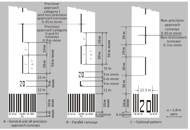
Figure L-1. Runway designation, centre line and threshold markings
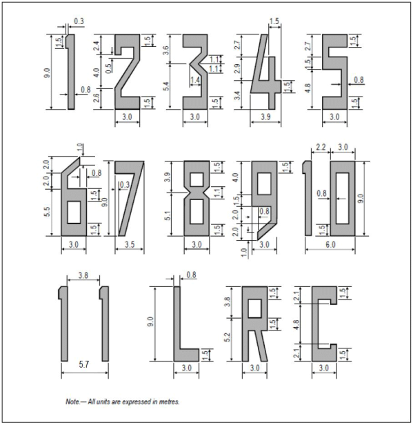
Figure L-2. Form and proportions of numbers and letters for runway designation markings
[Issue: ADR-DSN/3]
CS ADR-DSN.L.530 Runway centre line marking
ED Decision 2016/027/R
(a) Applicability: A runway centre line marking should be provided on a paved runway.
(b) Location: A runway centre line marking should be located along the centre line of the runway between the runway designation marking as shown in Figure L-1, except when interrupted as given in CS ADR-DSN.L.560.
(c) Characteristics:
(1) A runway centre line marking should consist of a line of uniformly spaced stripes and gaps. The length of a stripe plus a gap should be not less than 50 m or more than 75 m. The length of each stripe should be at least equal to the length of the gap or 30 m, whichever is greater.
(2) The width of the stripes should be not less than:
(i) 0.90 m on precision approach Category II and III runways;
(ii) 0.45 m on non-precision approach runways where the code number is 3 or 4, and precision approach Category I runways; and
(iii) 0.30 m on non-precision approach runways where the code number is 1 or 2, and on non-instrument runways.
[Issue: ADR-DSN/3]
GM1 ADR-DSN.L.530 Runway centre line marking
ED Decision 2014/013/R
For the centre line marking the 30 m length of and gap between stripes may be adjusted to take into consideration the runway thresholds locations.
CS ADR-DSN.L.535 Threshold marking
ED Decision 2016/027/R
(a) Applicability: A threshold marking should be provided at the threshold of a runway.
(b) Characteristics:
(1) The stripes of the threshold marking should commence 6 m from the threshold.
(2) A runway threshold marking should consist of a pattern of longitudinal stripes of uniform dimensions disposed symmetrically about the centre line of a runway as shown in Figure L-1(A) and L-1(B) for a runway width of 45 m. The number of stripes should be in accordance with the runway width as follows:
|
Runway width |
Number of stripes |
|
18 m |
4 |
|
23 m |
6 |
|
30 m |
8 |
|
45 m |
12 |
|
60 m |
16 |
except that on non-precision approach and non-instrument runways 45 m or greater in width, they may be as shown in Figure L-1(C).
(3) The stripes should extend laterally to within 3 m of the edge of a runway or to a distance of 27 m on either side of a runway centre line, whichever results in the smaller lateral distance.
(4) Where a runway designation marking is placed within a threshold marking, there should be a minimum of three stripes on each side of the centre line of the runway.
(5) Where a runway designation marking is placed above a threshold marking, the stripes should be continued across the runway. The stripes should be at least 30 m long and approximately 1.80 m wide with spacings of approximately 1.80 m between them. Where the stripes are continued across a runway, a double spacing should be used to separate the two stripes nearest the centre line of the runway, and in the case where the designation marking is included within the threshold marking, this spacing should be 22.5 m.
(c) Displaced threshold:
(1) Where a threshold is displaced from the extremity of a runway or where the extremity of a runway is not square with the runway centre line, a transverse stripe as shown in Figure L-3(B) should be added to the threshold marking.
(2) A transverse stripe should be not less than 1.80 m wide.
(3) Where a runway threshold is permanently displaced, arrows conforming to Figure L-3(B) should be provided on the portion of the runway before the displaced threshold.
(4) When a runway threshold is temporarily displaced from the normal position, it should be marked as shown in Figure L-3(A) or L-3(B), and all markings prior to the displaced threshold should be obscured except the runway centre line marking which should be converted to arrows.
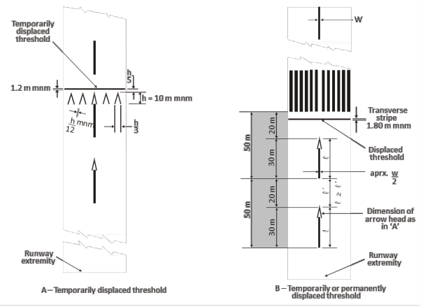
Figure L-3. Displaced threshold markings
[Issue: ADR-DSN/3]
CS ADR-DSN.L.540 Aiming point marking
ED Decision 2014/013/R
(a) Applicability:
(1) An aiming point marking should be provided at each approach end of an instrument runway where the code number is 2, 3, or 4.
(2) An aiming point marking should be provided when additional conspicuity of the aiming point is required at each approach end of:
(i) a non-instrument runway where the code number is 3 or 4,
(ii) an instrument runway where the code number is 1.
(b) Characteristics. The aiming point marking should commence no closer to the threshold than the distance indicated in the appropriate column of Table L-1, except that, on a runway equipped with a PAPI system, the beginning of the marking should be coincident with the visual approach slope origin.
|
Location and dimensions |
Landing distance available |
|||
|
Less than 800 m |
800 m up to but not including 1 200 m |
1 200 m up to but not including 2 400 m |
2 400 m and above |
|
|
(1) |
(2) |
(3) |
(4) |
(5) |
|
Distance from threshold to beginning of markinga |
150 m |
250 m |
300 m |
400 m |
|
Length of stripeb |
30-45 m |
30-45 m |
45-60 m |
45-60 m |
|
Width of stripe |
4 m |
6 m |
6-10 mc |
6-10 mc |
|
Lateral spacing between inner sides of stripes |
6 md |
9 md |
18-22.5 m |
18-22.5 m |
|
a Where a PAPI system is provided for the runway, the beginning of the marking should be coincident with the visual approach slope origin. b Where greater dimensions of the specified ranges are intended to be used where increased conspicuity is required. c Where lateral spacing may be varied within these limits to minimise the contamination of the marking by rubber deposits. d These figures were deduced by reference to the outer main gear wheel span which is element 2 of the aerodrome reference code |
||||
Table L-1. Location and dimensions of aiming point marking
(c) An aiming point marking should consist of two conspicuous stripes. The dimensions of the stripes and the lateral spacing between their inner sides should be in accordance with the provisions of the appropriate column of Table L-1.
GM1 ADR-DSN.L.540 Aiming point marking
ED Decision 2017/021/R
For runways with widths of 30 m, the width of the rectangular stripes of the aiming point marking and the lateral spacing between the inner sides of the stripes may be adjusted in proportion to the available runway width to avoid overlapping of the aiming point marking with the runway side stripe marking.
[Issue: ADR-DSN/4]
CS ADR-DSN.L.545 Touchdown zone marking
ED Decision 2016/027/R
(a) Applicability:
(1) A touchdown zone marking should be provided in the touchdown zone of a paved precision approach runway where the code number is 2, 3, or 4.
(2) A touchdown zone marking should be provided in the touchdown zone of a paved non-precision approach or non-instrument runway where the code number is 3 or 4 and additional conspicuity of the touchdown zone is desirable.
(b) Location: A touchdown zone marking should consist of pairs of rectangular markings symmetrically disposed about the runway centre line with the number of such pairs related to the landing distance available and, where the marking is to be displayed at both the approach directions of a runway, the distance between the thresholds, as follows:
|
Landing distance available or the distance between thresholds |
Pair(s) of markings |
|
less than 900 m |
1 |
|
900 m up to but not including 1 200 m |
2 |
|
1 200 m up to but not including 1 500 m |
3 |
|
1 500 m up to but not including 2 400 m |
4 |
|
2 400 m or more |
6 |
(c) Characteristics:
(1) A touchdown zone marking should conform to the patterns shown in Figure L-4. For the pattern shown in Figure L-4(A), the markings should be not less than 22.5 m long and 3 m wide. For the pattern shown in Figure L-4(B), each stripe of each marking should be not less than 22.5 m long and 1.8 m wide with spacing of 1.5 m between adjacent stripes.
(2) The lateral spacing between the inner sides of the rectangles should be equal to that of the aiming point marking where provided. Where an aiming point marking is not provided, the lateral spacing between the inner sides of the rectangles should correspond to the lateral spacing specified for the aiming point marking in Table L-1 (columns (2), (3), (4), or (5), as appropriate). The pairs of markings should be provided at longitudinal spacings of 150 m beginning from the threshold, except that pairs of touchdown zone markings coincident with or located within 50 m of an aiming point marking should be deleted from the pattern.
(3) On a non-precision approach runway where the code number is 2, an additional pair of touchdown zone marking stripes should be provided 150 m beyond the beginning of the aiming point marking.
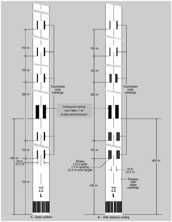
Figure L-4. Aiming point and touchdown zone markings (illustrated for a runway with a length of 2 400 m or more)
[Issue: ADR-DSN/3]
GM1 ADR-DSN.L.545 Touchdown zone marking
ED Decision 2014/013/R
(a) In order to give information regarding the overall extension of a distance coding touchdown marking, as specified in CS ADR-DSN.L.545, the last pair of markings after the threshold should consist of two single stripes, and the other pairs should correspond to the patterns shown in Figure L-4.
(b) Such sequential layout gives intuitive information about the extension of the touchdown zone and, as a consequence, of the LDA or of the distance between thresholds.
CS ADR-DSN.L.550 Runway side stripe marking
ED Decision 2014/013/R
(a) Applicability:
(1) A runway side stripe marking should be provided between the thresholds of a runway where there is a lack of contrast between the runway edges and the shoulders or the surrounding terrain.
(2) A runway side stripe marking should be provided on a precision approach runway irrespective of the contrast between the runway edges and the shoulders or the surrounding terrain.
(b) Location and characteristics:
(1) A runway side stripe marking should consist of two stripes, one placed along each edge of the runway with the outer edge of each stripe approximately on the edge of the runway, except that, where the runway is greater than 60 m in width, the stripes should be located 30 m from the runway centre line.
(2) Where a runway turn pad is provided, the runway side stripe marking should be continued between the runway and the runway turn pad.
(3) A runway side stripe should have an overall width of at least 0.9 m on runways 30 m or more in width and at least 0.45 m on narrower runways.
GM1 ADR-DSN.L.550 Runway side stripe marking
ED Decision 2014/013/R
When turn pads are not available at the end of a runway for back-track manoeuvres and threshold is displaced, in order to better identify full-strength bearing surface, it may be useful to display specific dashed markings as showed by Figure GM-L-1 and with dimensions described in Table GM-L-1.
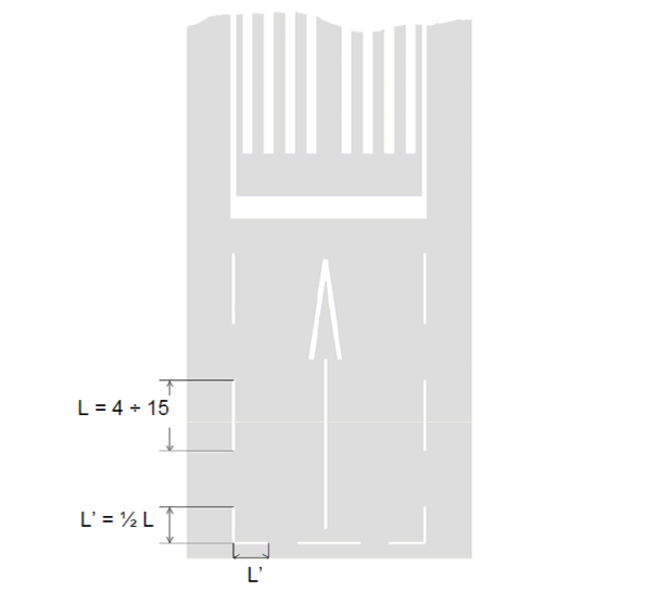
Figure GM-L-1. Dashed runway side stripe marking
|
Runway width (m) |
Single dash dimensions |
|
|
Length (minimum m) |
Width (m) |
|
|
60 |
15 |
0.45 |
|
45 |
15 |
0.45 |
|
30 |
10 |
0.45 |
|
23 |
6 |
0.25 |
|
18 |
4 |
0.25 |
|
Note: The length of the gap is as much as possible equal, but not longer, to the length of the corresponding marking |
||
Table GM-L-1. Dashed runway side stripe markings
CS ADR-DSN.L.555 Taxiway centre line marking
ED Decision 2022/006/R
(a) Applicability:
(1) Taxiway centre line marking should be provided on a taxiway, de-icing/anti-icing facility and apron in such a way as to provide continuous guidance between the runway centre line and aircraft stands.
(2) Taxiway centre line marking should be provided on a runway when the runway is part of a standard taxi-route and where the taxiway centre line is not coincident with the runway centre line.
(b) Characteristics:
(1) On a straight section of a taxiway, the taxiway centre line marking should be located along the taxiway centre line.
(2) On a taxiway curve, the marking should continue from the straight portion of the taxiway at a constant distance from the outside edge of the curve.
(3) At an intersection of a taxiway with a runway, where the taxiway serves as an exit from the runway, the taxiway centre line marking should be curved into the runway centre line marking as shown in Figure L-5. The taxiway centre line marking should be extended parallel to the runway centre line marking for a distance of at least 60 m beyond the point of tangency where the code number is 3 or 4, and for a distance of at least 30 m where the code number is 1 or 2.
(4) Where taxiway centre line marking is provided in accordance with (a)(2) above, the marking should be located on the centre line of the designated taxiway.
(5) A taxiway centre line marking should be at least 15 cm in width and continuous in length except where it intersects with a runway-holding position marking or an intermediate holding position marking as shown in Figure L-5. Taxiway markings (shown with basic runway markings).
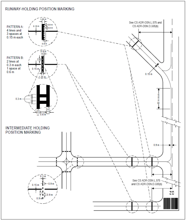
Figure L-5. Taxiway markings (shown with basic runway markings)
[Issue: ADR-DSN/3]
[Issue: ADR-DSN/6]
GM1 ADR-DSN.L.555 Taxiway centre line marking
ED Decision 2016/027/R
The term ‘continuous guidance’ is not intended to require that taxiway centre line markings are provided onto aircraft stands. Instead, it is intended that the centre line marking be provided on taxiways leading to aircraft stands or other apron areas from which visual cues or other means exist, such as lead-in arrows and stand number indicators, to enable aircrew to manoeuvre the aircraft onto a stand or other parking area.
[Issue: ADR-DSN/3]
CS ADR-DSN.L.560 Interruption of runway markings
ED Decision 2014/013/R
(a) At an intersection of two (or more) runways, the markings of the more important runway, except for the runway side stripe marking, should be displayed and the markings of the other runway(s) should be interrupted. The runway side stripe marking of the more important runway should be either continued across the intersection or interrupted.
(b) The order of importance of runways for the display of runway markings should be as follows:
(1) precision approach runway;
(2) non-precision approach runway; and
(3) non-instrument runway.
(c) At an intersection of a runway and taxiway the markings of the runway should be displayed and the markings of the taxiway interrupted, except that runway side stripe markings should be either continued across the intersection or interrupted.
GM1 ADR-DSN.L.560 Interruption of runway markings
ED Decision 2017/021/R
(a) At an intersection of a runway and taxiway, the runway side stripe marking should be either continued across the intersection or interrupted. The interruption means one of the following:
(1) the runway side stripe marking stops at the point where the taxiway fillet starts at either side of the taxiway (see Figure GM-L-2(A)); or
(2) the runway side stripe marking stops at the point where the extended line of the taxiway edge crosses the runway (see Figure GM-L-2(B)); or
(3) the runway side stripe marking stops at a short distance on either side of the taxiway centre line marking in order to allow visible and continuous taxiway centre line marking guidance (see Figure GM-L-2(C)); or
(4) the taxiway centre line marking overlays and therefore interrupts a continuous runway side stripe marking (see Figure GM-L-2(D)).
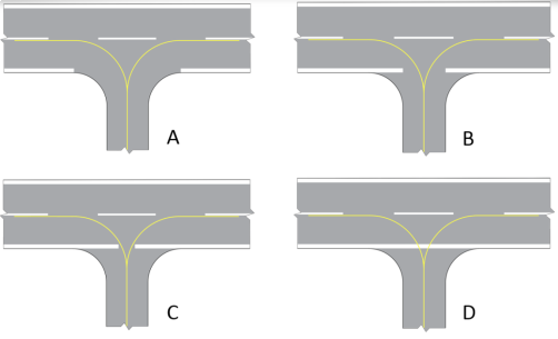
Figure GM-L-2. Illustration of runway side stripe marking interruption
(b) The overall perception of the runway side stripe marking depends on conspicuity needs and local conditions, such as the number, location and disposition of runway/taxiway intersections, nature of the surrounding terrain, operational needs at aerodrome, weather, etc.
[Issue: ADR-DSN/4]
CS ADR-DSN.L.565 Runway turn pad marking
ED Decision 2017/021/R
(a) Applicability: Where a runway turn pad is provided, a runway turn pad marking should be provided for continuous guidance to enable an aeroplane to complete a 180-degree turn and align with the runway centre line.
(b) Characteristics:
(1) The runway turn pad marking should be curved from the runway centre line into the turn pad. The radius of the curve should be compatible with the manoeuvring capability and normal taxiing speeds of the aeroplanes for which the runway turn pad is intended.
(2) The intersection angle of the runway turn pad marking with the runway centre line should not be greater than 30 degrees.
(3) The runway turn pad marking should be extended parallel to the runway centre line marking for a distance of at least 60 m beyond the point of tangency where the code number is 3 or 4, and for a distance of at least 30 m where the code number is 1 or 2.
(4) A runway turn pad marking should guide the aeroplane in such a way as to allow a straight portion of taxiing before the point where a 180-degree turn is to be made. The straight portion of the runway turn pad marking should be parallel to the outer edge of the runway turn pad.
(5) The design of the curve allowing the aeroplane to negotiate a 180-degree turn should be based on a nose wheel steering angle not exceeding 45 degrees.
(6) The design of the turn pad marking should be such that when the cockpit of the aeroplane remains over the runway turn pad marking, the clearance distance between any wheel of the aeroplane landing gear and the edge of the runway turn pad should be not less than those specified in CS ADR-DSN.B.095(c).
(7) A runway turn pad marking should be at least 15 cm in width and continuous in length.
[Issue: ADR-DSN/4]
GM1 ADR-DSN.L.565 Runway turn pad marking
ED Decision 2017/021/R
Where a runway turn pad is not provided, a marking for continuous guidance to enable an aeroplane to complete a 180-degree turn and align with the runway centre line may be provided. Such marking should be yellow, at least 15 cm in width and continuous in length.
[Issue: ADR-DSN/4]
CS ADR-DSN.L.570 Enhanced taxiway centre line marking
ED Decision 2022/006/R
(a) Where provided, an enhanced taxiway centre line marking should be installed at each taxiway/runway intersection where it is necessary to denote the proximity of a runway-holding position.
(b) Characteristics:
(1) Enhanced taxiway centre line marking should be as shown in Figure L-6. An enhanced taxiway centre line marking should extend from the runway-holding position Pattern A (as defined in Figure L-5) to a distance of up to 47 m in the direction of travel away from the runway (see Figure L-6(a)).
(2) If the enhanced taxiway centre line marking intersects another runway-holding position marking, such as for a precision approach Category II or III runway, that is located within 47 m of the first runway-holding position marking, the enhanced taxiway centre line marking should be interrupted 0.9 m prior to and after the intersected runway-holding position marking. The enhanced taxiway centre line marking should continue beyond the intersected runway-holding position marking for at least three dashed line segments or 47 m from start to finish, whichever is greater (see Figure L-6(b)).
(3) If the enhanced taxiway centre line marking continues through a taxiway/taxiway intersection that is located within 47 m of the runway-holding position marking, the enhanced taxiway centre line marking should be interrupted 1.5 m prior to and after the point where the intersected taxiway centre line crosses the enhanced taxiway centre line. The enhanced taxiway centre line marking should continue beyond the taxiway/taxiway intersection for at least three dashed line segments or 47 m from start to finish, whichever is greater (see Figure L-6(c)).
(4) Where two taxiway centre lines converge at or before the runway-holding position marking, the inner dashed line should not be less than 3 m in length (see Figure L-6(d)).
(5) Where there are two opposing runway-holding position markings and the distance between the markings is less than 94 m, the enhanced taxiway centre line markings should extend over this entire distance. The enhanced taxiway centre line markings should not extend beyond either runway-holding position marking (see Figure L-6(e)).
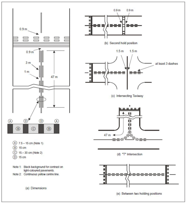
Figure L-6. Enhanced taxiway centre line marking
[Issue: ADR-DSN/3]
[Issue: ADR-DSN/6]
GM1 ADR-DSN.L.570 Enhanced taxiway centre line marking
ED Decision 2016/027/R
The provision of enhanced taxiway centre line marking may form part of runway incursion prevention measures.
[Issue: ADR-DSN/3]
CS ADR-DSN.L.575 Runway-holding position marking
ED Decision 2016/027/R
A runway-holding position marking should be displayed along a runway-holding position.
(a) Characteristics:
(1) At an intersection of a taxiway and a non-instrument, non-precision approach or take-off runway, the runway-holding position marking should be as shown in Figure L-5, pattern A.
(2) Where a single runway-holding position is provided at an intersection of a taxiway and a precision approach Category I, II or III runway, the runway-holding position marking should be as shown in Figure L-5, pattern A.
(3) Where two or three runway-holding positions are provided at such an intersection, the runway-holding position marking closer (closest) to the runway should be as shown in Figure L-5, pattern A, and the markings farther from the runway should be as shown in Figure L-5, pattern B.
(4) The runway-holding position marking displayed at a runway-holding position established in accordance with CS ADR-DSN.D.335(b)(1) should be as shown in Figure L-5, pattern A.
(5) Where increased conspicuity of the runway-holding position is required, the runway-holding position marking should be as shown in Figure L-7, pattern A or pattern B, as appropriate.
(6) Where a pattern B runway-holding position marking is located on an area where it would exceed 60 m in length, a mandatory instruction marking containing the term ‘CAT II’ or ‘CAT III’ as appropriate should be marked on the surface at the ends of the runway-holding position marking and at equal intervals of 45 m maximum between successive marks. The letters should be not less than 1.8 m high and should be placed not more than 0.9 m on the holding side of the runway holding position marking.
(7) The runway-holding position marking displayed at a runway/runway intersection should be perpendicular to the centre line of the runway forming part of the standard taxi-route. The pattern of the marking should be as shown in Figure L-7, pattern A.
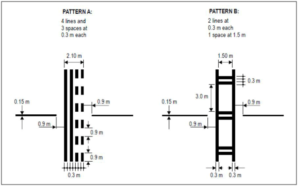
Figure L-7. Runway-holding position markings
[Issue: ADR-DSN/3]
GM1 ADR-DSN.L.575 Runway-holding position marking
ED Decision 2014/013/R
When the Runway-holding position marking is supplemented with the term ‘CAT II’ or ‘CAT III’ on the areas or taxiways exceeding 60 m in accordance with CS ADR-DSN.L.575(a)(6) and should be placed along with the Mandatory instruction marking in accordance with CS ADR-DSN.L.605 both markings should be equally and symmetrically placed one next to another.
CS ADR-DSN.L.580 Intermediate holding position marking
ED Decision 2016/027/R
(a) Applicability:
(1) An intermediate holding position marking should be displayed along an intermediate holding position.
(2) An intermediate holding position marking should be displayed at the exit boundary of a remote de-icing/anti-icing facility adjoining a taxiway.
(b) Location:
(1) Where an intermediate holding position marking is displayed at an intersection of two taxiways, it should be located across the taxiway at sufficient distance from the near edge of the intersecting taxiway to ensure safe clearance between taxiing aircraft. It should be coincident with a stop bar or intermediate holding position lights where provided.
(2) The distance between an intermediate holding position marking at the exit boundary of a remote de-icing/anti-icing facility and the centre line of the adjoining taxiway should not be less than the dimension specified in the table below.
|
Code letter |
Distance (metres) |
|
A |
15.5 |
|
B |
20 |
|
C |
26 |
|
D |
37 |
|
E |
43.5 |
|
F |
51 |
(c) Characteristics: An intermediate holding position marking should consist of a single broken line as shown in Figure L-5.
[Issue: ADR-DSN/3]
GM1 ADR-DSN.L.580 Intermediate holding position marking
ED Decision 2014/013/R
intentionally left blank
CS ADR-DSN.L.585 VOR aerodrome checkpoint marking
ED Decision 2016/027/R
(a) Applicability: When a VOR aerodrome check-point is established, it should be indicated by a VOR aerodrome check-point marking and sign.
(b) Location: A VOR aerodrome check-point marking should be centred on the spot at which an aircraft is to be parked to receive the correct VOR signal.
(c) Characteristics:
(1) A VOR aerodrome check-point marking should consist of a circle 6 m in diameter and have a line width of 15 cm (see Figure L-8(A)).
(2) When it is preferable for an aircraft to be aligned in a specific direction, a line should be provided that passes through the centre of the circle on the desired azimuth. The line should extend 6 m outside the circle in the desired direction of heading and terminate in an arrowhead. The width of the line should be 15 cm (see Figure L-8(B)).
(3) A VOR aerodrome check-point marking should differ from the colour used for the taxiway markings and when applicable from a contrasting viewpoint, be white in colour.
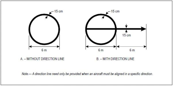
Figure L-8. VOR check-point markings
[Issue: ADR-DSN/3]
GM1 ADR-DSN.L.585 VOR aerodrome checkpoint marking
ED Decision 2016/027/R
Further guidance on the selection of sites for VOR aerodrome checkpoints is given in ICAO Annex 10, Volume I, Attachment E.
[Issue: ADR-DSN/3]
CS ADR-DSN.L.590 Aircraft stand marking
ED Decision 2014/013/R
(a) Applicability: Aircraft stand markings should be provided for designated parking positions on an apron and on a de-icing/anti-icing facility.
(b) General characteristics: Aircraft stand markings should include such elements as stand identification, lead-in line, turn bar, turning line, alignment bar, stop line and lead-out line as are required by the parking configuration and to complement other parking aids.
(c) Aircraft stand identification:
(1) An aircraft stand identification (letter and/or number) should be included in the lead-in line a short distance after the beginning of the lead-in line. The height of the identification should be adequate to be readable from the cockpit of aircraft using the stand.
(2) Identification of the aircraft for which each set of markings is intended, should be added to the stand identification where two sets of aircraft stand markings are superimposed on each other in order to permit more flexible use of the apron and safety would be impaired if the wrong marking was followed.
(d) Lead-in, turning, and lead-out lines:
(1) Lead-in, turning, and lead-out lines should, as far as practicable, be continuous in length and have a width of not less than 15 cm. Where one or more sets of stand markings are superimposed on a stand marking, the lines should be continuous for the most demanding aircraft and broken for other aircraft.
(2) The curved portions of lead-in, turning, and lead-out lines should have radii appropriate to the most demanding aircraft type for which the markings are intended.
(3) Where it is intended that an aircraft proceeds in one direction only, arrows pointing in the direction to be followed should be added as part of the lead-in and lead-out lines.
(e) Alignment bar: An alignment bar should be placed so as to be coincident with the extended centre line of the aircraft in the specified parking position and visible to the pilot during the final part of the parking manoeuvre. It should have a width of not less than 15 cm.
(f) Turn bar and stop line:
(1) A turn bar should be located at right angles to the lead-in line, abeam the left pilot position at the point of initiation of any intended turn. It should have a length and width of not less than 6 m and 15 cm respectively, and include an arrowhead to indicate the direction of turn.
(2) A stop line should be located at right angles to the alignment bar, abeam the left pilot position at the intended point of stop. It should have a length and width of not less than 6 m and 15 cm respectively.
(3) If more than one turn bar and/or stop line is required, they should be designated for the appropriate aircraft types.
GM1 ADR-DSN.L.590 Aircraft stand marking
ED Decision 2014/013/R
(a) The distances to be maintained between the stop line and the lead-in line may vary according to different aircraft types, taking into account the pilot’s field of view.
(b) Apron markings are installed to support the safe operation of aircraft on stands and apron areas. Where appropriate procedures are employed, markings may not be required, giving flexibility of operations. Examples would include situations where aircraft marshallers are used or where aircraft are required to self-park on an open apron where different combinations of aircraft preclude dedicated markings. Specific markings/stands are normally more applicable for larger aircraft.
CS ADR-DSN.L.595 Apron safety lines
ED Decision 2014/013/R
(a) Applicability: Apron safety lines should be provided on an apron as required by the parking configurations and ground facilities.
(b) Location: Apron safety lines should be located so as to define the areas intended for use by ground vehicles and other aircraft servicing equipment to provide safe separation from aircraft.
(c) Characteristics:
(1) Apron safety lines should include such elements as wing tip clearance lines and service road boundary lines as required by the parking configurations and ground facilities.
(2) Apron safety lines should be of a conspicuous colour which should contrast with that used for aircraft stand markings.
(3) An apron safety line should be continuous in length and at least 10 cm in width.
GM1 ADR-DSN.L.595 Apron safety lines
ED Decision 2016/027/R
(a) Ground equipment and vehicles should be kept outside predetermined limits when aircraft are manoeuvring or when the equipment is left unattended.
(b) Safety lines are required on an apron to mark the limits of parking areas for ground equipment, apron service roads and passengers’ paths, etc. These lines are narrower and of a different colour to differentiate them from the guidelines used for aircraft.
(1) Wing tip clearance lines. These lines should delineate the safety zone clear of the path of the critical aeroplane wing tip. The line should be drawn at appropriate distance outside the normal path of the wing tip of the critical aeroplane;
(2) Equipment limit lines. These lines are used to indicate the limits of areas which are intended for parking vehicles and aircraft servicing equipment when they are not in use.
(c) Several methods may be used to identify which side of a safety line is safe for storage of such vehicles and equipment:
(1) Spurs or an additional line (a discontinuous line of the same colour or a continuous line of a different conspicuous colour) may be provided on one side of the safety line. The side on which such spurs or an additional line is located is considered safe for parking vehicles and equipment;
(2) The words ‘Equipment Limit’ may be painted on the side used by ground equipment and readable from that side;
(3) Passenger path lines. These lines are used to indicate to passengers and escorting personnel the route that needs to be followed, when walking on the apron, in order to be clear of hazards. A pair of lines with zebra hatching between them may be used.
[Issue: ADR-DSN/3]
CS ADR-DSN.L.597 Apron service road marking
ED Decision 2016/027/R
(a) Applicability: The limits of an apron service road, should be defined by apron service road markings.
(b) Location: Apron service road markings should define the areas intended for use by ground vehicles and other aircraft servicing equipment to provide safe separation from aircraft.
(c) Characteristics:
(1) Apron service road markings should be white.
(2) Apron service road markings should be continuous in length on the edges, continuous or broken in the middle, as appropriate, and at least 10 cm in width.
(3) When an apron service road crosses a taxiway or aircraft stand taxilane, the apron service road edge marking should be laterally dashed along the crossing. The stripes should be 1.0 m in length, and their width should be equal to the width of the continuous part of the marking.
(d) Apron service road markings should be discontinued when they intersect with other markings on an apron. The interrupted gap should be not more than 1 m on each side from the edge of the interested marking.
[Issue: ADR-DSN/3]
GM1 ADR-DSN.L.597 Apron service road marking
ED Decision 2016/027/R
(a) The term service road encompasses also other types of roads, such as the perimeter service roads, which are used to provide access to security or maintenance services etc. of the aerodrome. However, such types of service roads do not fall under the term ‘apron service road’.
(b) When an apron service road crosses a taxiway, a separate road-holding position sign, in accordance with CS ADR-DSN.N.800, or road-holding position marking, in accordance with CS ADR-DSN.L.600, should indicate that vehicles are required to stop.
(c) Markings located on an apron are prescribed in CS ADR-DSN.L.555, CS ADR-DSN.L.590 and CS ADR-DSN.L.595.
[Issue: ADR-DSN/3]
CS ADR-DSN.L.600 Road-holding position marking
ED Decision 2016/027/R
(a) Applicability: A road-holding position marking should be provided at all road entrances or intersections to a runway or a taxiway.
(b) Location:
(1) The road-holding position marking should be located across the road at the holding position.
(2) Where a road intersects a taxiway, a road-holding position marking should be located across the road at the appropriate distance to ensure vehicles remain clear of the taxiway strip.
(c) Characteristics:
(1) The road-holding position marking should be in accordance with the local road traffic regulations.
(2) The road-holding position marking at the intersection of a road with a taxiway should be in accordance with the local traffic regulations for a yield right-of-way or mandatory stop.
[Issue: ADR-DSN/3]
GM1 ADR-DSN.L.600 Road-holding position marking
ED Decision 2016/027/R
(a) Where a road that accesses a runway or a taxiway is unpaved, it may not be possible to install markings. In such cases, a road-holding position signs and/or lights should be installed, combined with appropriate instructions on how the driver of a vehicle should proceed.
(b) Where it is possible to install markings, they should conform to national regulations for traffic sings and markings.
[Issue: ADR-DSN/3]
CS ADR-DSN.L.605 Mandatory instruction marking
ED Decision 2022/006/R
(a) Applicability:
(1) Where a mandatory instruction sign in accordance with CS ADR-DSN.N.780 is not installed, a mandatory instruction marking should be provided on the surface of the pavement.
(2) On taxiways exceeding 60 m in width, or to assist in the prevention of a runway incursion, a mandatory instruction sign should be supplemented by a mandatory instruction marking.
(b) Location:
(1) The mandatory instruction marking on taxiways, where the code letter is A, B, C, or D, should be located across the taxiway equally placed about the taxiway centre line and on the holding side of the runway-holding position marking as shown in Figure L-9(A). The distance between the nearest edge of the marking and the runway-holding position marking or the taxiway centre line marking should be not less than 1 m.
(2) The mandatory instruction marking on taxiways where the code letter is E or F, should be located on the both sides of the taxiway centre line marking and on the holding side of the runway-holding position marking as shown in Figure L-9(B). The distance between the nearest edge of the marking and the runway-holding position marking, or the taxiway centre line marking should be not less than 1 m.
(c) Characteristics:
(1) A mandatory instruction marking should consist of an inscription in white on a red background. Except for a no-entry marking, the inscription should provide information identical to that of the associated mandatory instruction sign.
(2) A no-entry marking should consist of an inscription in white reading NO ENTRY on a red background.
(3) Where there is insufficient contrast between the marking and the pavement surface, the mandatory instruction marking should include an appropriate border, preferably white or black.
(4) The character height should be 4 m for inscriptions where the code letter is C, D, E, or F, and at least 2 m where the code letter is A or B. The inscription should be in the form and proportions shown in Figures L-10A to L-10D.
(5) The background should be rectangular and extend a minimum of 0.5 m laterally and vertically beyond the extremities of the inscription.
(6) The spacing of characters for mandatory instruction marking should be obtained by first determining the equivalent elevated sign character height and then proportioning from the spacing values given in Table N-3.
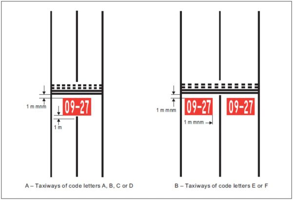
Figure L-9. Mandatory instruction marking
[Issue: ADR-DSN/3]
[Issue: ADR-DSN/4]
[Issue: ADR-DSN/6]
GM1 ADR-DSN.L.605 Mandatory instruction marking
ED Decision 2017/021/R
(a) Except where operationally required, a mandatory instruction marking should not be located on a runway.
(b) The mandatory instruction markings and information markings on pavements are formed as if shadowed (i.e. stretched) from the characters of an equivalent elevated sign by a factor of 2.5, as illustrated in Figure GM-L-3. The shadowing only affects the vertical dimension.
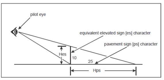
Figure GM-L-3. Illustration of pavement marking spacing calculation
(c) The following example illustrates how the pavement marking spacing is to be calculated:
(1) in the case of runway designator ‘10’, which is to have a height of 4 000 mm (Hps), the equivalent elevated sign character height is 4 000/2.5 = 1 600 mm (Hes);
(2) Table N-3(b) indicates numeral to numeral code 1 and from Table N-3(c) this code has a dimension of 96 mm, for a character height of 400 mm;
(3) the pavement marking spacing for ‘10’ is then (1 600/400) x 96 = 384 mm.
[Issue: ADR-DSN/4]
CS ADR-DSN.L.610 Information marking
ED Decision 2022/006/R
(a) Applicability: Where an information sign in accordance with CS ADR-DSN.N.785 is not installed, an information marking should be displayed on the surface of the pavement.
(b) Characteristics:
(1) An information marking should consist of:
(i) an inscription in yellow upon a black background when it replaces or supplements a location sign; and
(ii) an inscription in black upon a yellow background when it replaces or supplements a direction or destination sign.
(2) Where there is insufficient contrast between the marking background and the pavement surface, the marking should include:
(i) a black border where the inscriptions are in black; and
(ii) a yellow border where the inscriptions are in yellow.
(3) The character height, spacing, and the form and proportions of the inscription should be as for mandatory instruction markings.
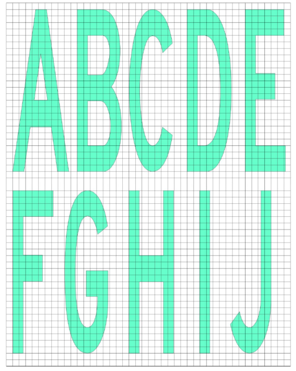
Figure L-10A. Mandatory instruction marking inscription form and proportions
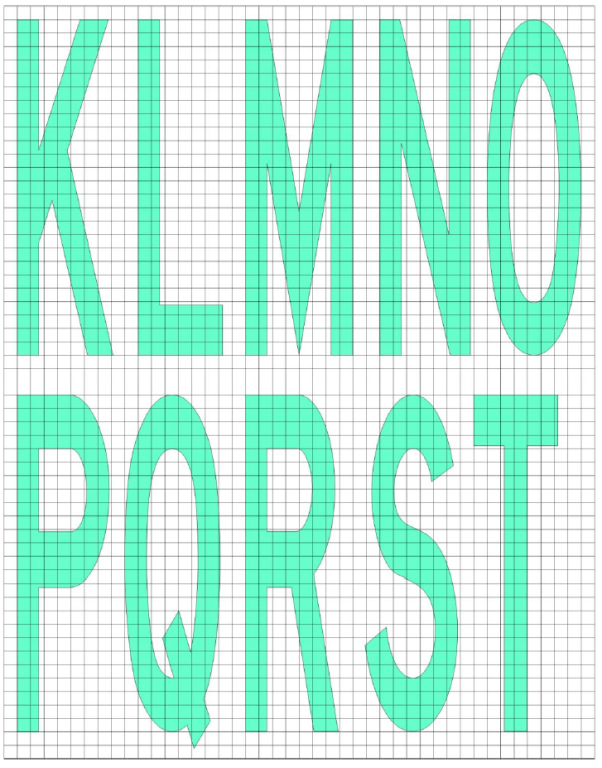
Figure L-10B. Mandatory instruction marking inscription form and proportions
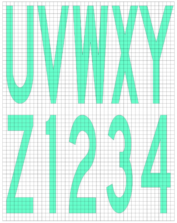
Figure L-10C. Mandatory instruction marking inscription form and proportions
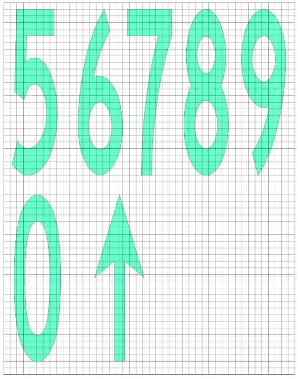
Figure L-10D. Mandatory instruction marking inscription form and proportions
[Issue: ADR-DSN/3]
[Issue: ADR-DSN/4]
[Issue: ADR-DSN/6]
GM1 ADR-DSN.L.610 Information marking
ED Decision 2014/013/R
(a) Applicability: Where operationally required information sign should be supplemented by a marking on the pavement surface.
(b) Location:
(1) An information (location/direction) marking should be displayed prior to and following complex taxiway intersections, and where operational experience has indicated the addition of a taxiway location marking could assist flight crew ground navigation, and on the pavement surface at regular intervals along taxiways of great length.
(2) The information marking should be displayed across the surface of the taxiway or apron where necessary, and positioned so as to be legible from the cockpit of an approaching aircraft.