
CS ADR-DSN.C.210 Runway end safety areas (RESA)
ED Decision 2016/027/R
(a) The safety objective of the runway end safety area (RESA) is to minimise risks to aircraft and their occupants when an aeroplane overruns or undershoots a runway.
(b) A runway end safety area should be provided at each end of a runway strip where:
(1) the code number is 3 or 4; and
(2) the code number is 1 or 2 and the runway is an instrument one.
(c) Where practicable, a runway end safety area should be provided at each end of a runway strip where the code number is 1 or 2 and the runway is a non-instrument one.
[Issue: ADR-DSN/3]
GM1 ADR-DSN.C.210 Runway end safety areas (RESA)
ED Decision 2022/006/R
(a) General
(1) A runway end safety area should provide an area long and wide enough, and suitable to contain overruns and undershoots resulting from a reasonably probable combination of adverse operational factors. On a precision approach runway, the ILS localiser is normally the first upstanding obstacle, and the runway end safety area should extend up to this facility. In other circumstances, the first upstanding obstacle may be a road, a railroad, or other constructed or natural feature. The provisions of a runway end safety area should take such obstacle into consideration.
(2) Whatever length of RESA is provided, it is important to ensure that likelihood of, and potential impacts arising from an overrun are minimised as far as reasonably practicable.
(3) It is recognised that achieving the recommended distance could present challenges. Therefore, the aim of this guidance is to identify the types of aerodrome activities that can be undertaken to reduce the likelihood and consequences of an overrun occurring, and to decide on appropriate actions and it is suggested that aerodrome operators assess their RESA provisions.
(4) The overrun is a complex risk to assess because there are a number of variables, such as prevailing weather, type of aeroplane, the landing aids available, runway characteristics and available distances, the surrounding environment, and human factors. Each of these can have a significant contribution to the overall hazard; furthermore, the nature of the hazard and level of risk should be different for each aerodrome and even for each runway direction at any one aerodrome. The aerodrome may address some, and these are included below. Additionally, aircraft operating procedures may impact but the aerodrome may have little ability to influence these. This should not prevent aerodromes from working with aircraft operators so that the operations are conducted so as to minimise the likelihood of an overrun occurring.
(5) Noting the requirement for a runway end safety area (RESA) consideration should be given to providing an area long enough to contain overruns and undershoots resulting from a reasonably probable combination of adverse operational factors. Therefore, aerodromes should try to maximise the length of RESA available on all applicable runways. When considering the RESA distance required for individual circumstances, aerodromes operators should take into account factors, such as:
(i) the runway length and slope, in particular the general operating lengths required for take-off and landing versus the runway distances available, including the excess of available length over that required;
(ii) current RESA provision (length & width – how much the RESA complies with the recommended distance) and options to increase or improve this;
(iii) the nature and location of any hazard beyond the runway end, including the topography and obstruction environment in and beyond the RESA and outside the runway strip;
(iv) the type of aeroplane and level of traffic at the aerodrome, and actual or proposed changes to either;
(v) aircraft performance limitations arising from runway and RESA length – high performance aircraft, operating at high loads and speeds have greater length requirements than smaller, low-performance aircraft, the relationship between required balanced field length and available distances;
(vi) navigation aids available (PBN, instrument or visual - if an ILS is only available on one runway direction, a downwind approach and landing may be necessary in poor weather) and the availability of vertical guidance ;
(vii) friction and drainage characteristics of the runway, which impact on runway susceptibility to surface contamination and aeroplane braking action;
(viii) traffic density, which may lead to increased pressure to vacate so increased speed;
(ix) aerodrome weather patterns, including wind shear;
(x) aerodrome overrun history; and
(xi) overrun/undershoot causal factors.
(b) Assessment of runway end safety areas
(1) The RESA assessment should help the aerodrome operator identify the hazards and appropriate actions to reduce the risk. A range of measures may be available, singly or in combination, to reduce the risks of an overrun occurring or becoming an accident. Measures aimed at reducing the likelihood of an overrun/undershoot include:
(i) improving runway surfaces and friction measurement, particularly when the runway is contaminated — know your runways and their condition and characteristics in precipitation;
(ii) ensuring that accurate and up-to-date information on weather, the runway state and characteristics, is notified and passed to flight crews in a timely way, particularly when flight crews need to make operational adjustments;
(iii) improving an aerodrome management’s knowledge, recording, prediction and dissemination of wind data, including wind shear, and any other relevant weather information, particularly when it is a significant feature of an aerodrome’s weather pattern;
(iv) upgrading visual and instrument landing aids to improve the accuracy of aeroplane delivery at the correct landing position on runways (including the provision of Instrument Landing PBN approach systems, location of aiming point and harmonisation with PAPIs);
(v) formulating, in consultation with aeroplane operators, adverse weather and any other relevant aerodrome operating procedures or restrictions, and promulgating such information appropriately; and
(vi) working with aircraft operators to optimise the operation.
(2) Combined with this, measures may be considered that would reduce the severity of the consequences should an event occur. Wherever practicable, aerodrome operators should seek to optimise the RESA. This may be achieved through a combination of:
(i) relocation, shifting or realignment of the runway — it may be possible to construct additional pavement at the start of take-off end to make more pavement available to retain the declared distances. The start and end of declared distances can be moved towards the downwind (start of take-off) end, thereby retaining the declared distance and creating space for a longer RESA, as shown in
GM1 ADR-DSN.B.035;
(ii) in the case where undershoot RESA is limited and the runway has a displaced landing threshold, examine whether the threshold can be moved (downwind) to increase the RESA and/or runway length;
(iii) reducing runway declared distances in order to provide the necessary RESA may be a viable option where the existing runway length exceeds that required for the existing or projected design aircraft. If the take-off distance required for the critical aircraft operating at the aerodrome is less than the take-off distance available, there may be an opportunity to reduce the relevant runway declared distances. Where provision of a runway end safety area would be particularly prohibitive to implement consideration would have to be given to reducing some of the declared distances of the runway for the provision of a runway end safety area and/or installation of an arresting system;
(iv) increasing the length of a RESA, and/or minimising the obstruction environment in the area beyond the RESA. Means to increase the RESA provision include land acquisition, improvements to the grading, realigning fences or roads to provide additional area;
(v) installing an arresting system according to CS ADR-DSN.C.236 (EMAS), or another suitably positioned and designed type of an arresting system, to supplement or as an alternative to a RESA where an equivalent level of safety is demonstrated;
(vi) improving the slopes in the RESA to minimise or remove downward slopes; and
(vii) providing paved RESA with known friction characteristics.
(3) A runway meant for take-off and landing in both directions should have 2 RESAs extending for the required distance beyond the end of the strip extending from the runway end. Depending of the position of the threshold on a runway, the RESA related to the reverse runway should protect aircraft undershooting the threshold. Assessments of overruns and undershoots have shown that the likelihood of an undershoot is approximately four times less than for an overrun. Additionally, the undershoot rate shows that the likelihood of an event is further reduced by the availability of precision approach aids, especially those with vertical guidance. Therefore, on a precision approach runway consideration may include whether to reduce the minimum length of RESA towards the length of the runway strip before the runway.
(4) It is recognised that improving RESAs is often difficult. However, it is important to note that incremental gains should be obtained wherever possible, as any gain is valuable. Therefore, whenever a runway project involves construction, consideration should also be given to improving the RESA.
(5) The above lists are not in any particular order, are not exhaustive, and should complement action by aeroplane operators, designers and aviation regulators.
(6) RESA provision should be considered by the Local Runway Safety Team.
(c) Arresting systems on runway end safety areas
(1) Arresting systems can be predictable and effective in arresting aeroplane overruns.
(2) Arresting system designs should be supported by a validated design method that can predict the performance of the system. The design method should be derived from field or laboratory tests. Testing may be based either on passage of an actual aircraft or an equivalent single wheel load through a test bed. The design should consider multiple aircraft parameters, including but not limited to allowable aircraft gear loads, gear configuration, tire contact pressure, aircraft centre of gravity, and aircraft speed. The model should calculate imposed aircraft gear loads, g-forces on aircraft occupants, deceleration rates, and stopping distances within the arresting system.
(3) Demonstrated performance of an arresting system can be achieved by a validated design method which can predict the performance of the system. The design and performance should be based on the type of aeroplane anticipated to use the associated runway that imposes the greatest demand upon the arresting system. The design of an arresting system should be based on a critical (or design) aircraft which is defined as aircraft using the associated runway that imposes the greatest demand upon the arresting system. This is usually but not always, the heaviest/largest aircraft that regularly uses the runway. Arresting system performance is dependent not only on aircraft weight but allowable aeroplane gear loads, gear configuration, tire contact pressure, aeroplane centre of gravity and aeroplane speed. Accommodating undershoots should also be addressed. All configurations should be considered in optimising the arresting system design. The aerodrome operator and arresting system manufacturer should consult regarding the selection of the design aeroplane that should optimise the arresting system for a particular aerodrome. Additionally, the design should allow the safe operation of fully loaded rescue and fire fighting vehicles, including their ingress and egress.
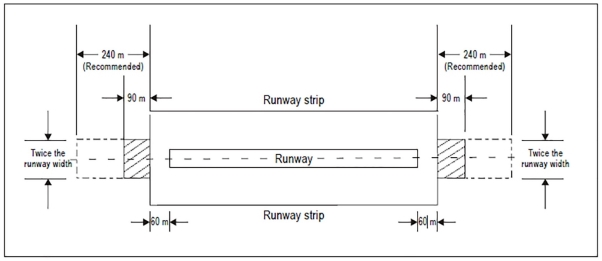
Figure GM-C-1. Runway end safety area for a runway where the code number is 3 or 4
[Issue: ADR-DSN/3]
[Issue: ADR-DSN/6]
CS ADR-DSN.C.215 Dimensions of runway end safety areas
ED Decision 2016/027/R
(a) Length of runway end safety area
(1) A runway end safety area should extend from the end of a runway strip to a distance of at least 90 m and, as far as practicable, extend to a distance of:
(i) 240 m where the code number is 3 or 4 and
(ii) 120 m where the code number is 1 or 2 and the runway is an instrument one; and
(2) A runway end safety area should extend from the end of a runway strip, as far as practicable, to a distance of 30 m where the code number is 1 or 2 and the runway is a non-instrument one.
(b) Notwithstanding the provisions in (a) above, the length of the runway end safety area may be reduced where an arresting system is installed, based on the design specifications of the system.
(c) Width of runway end safety area
The width of a runway end safety area should be at least twice that of the associated runway and, wherever practicable, be equal to that of the graded portion of the associated runway strip.
[Issue: ADR-DSN/3]
GM1 ADR-DSN.C.215 Dimensions of runway end safety areas
ED Decision 2014/013/R
It is accepted that many aerodromes were constructed before requirements for RESAs were introduced. For applicable runways where the RESA does not extend to the recommended distance, as part of their Safety Management System, aerodromes should assess the risk and implement appropriate and suitable mitigation measures as necessary.
CS ADR-DSN.C.220 Objects on runway end safety areas
ED Decision 2014/013/R
No fixed object, other than equipment and installations required for air navigation or for aeroplane safety purposes and satisfying the relevant frangibility requirement CS ADR-DSN.T.910, should be permitted on a runway end safety area. The detailed requirements for siting objects on a RESA are in CS ADR-DSN.T.915.
GM1 ADR-DSN.C.220 Objects on runway end safety areas
ED Decision 2014/013/R
Information regarding siting of equipment and installations on operational areas, including RESA, is detailed in CS ADR-DSN.T.915.
CS ADR-DSN.C.225 Clearing and grading of runway end safety areas
ED Decision 2014/013/R
A runway end safety area should provide a cleared and graded area for aeroplanes which the runway is intended to serve in the event of an aeroplane undershooting or overrunning the runway.
GM1 ADR-DSN.C.225 Clearing and grading of runway end safety areas
ED Decision 2016/027/R
(a) The surface of the runway end safety area should be prepared but does not need to be prepared to the same quality as the runway strip.
(b) Guidance on clearing and grading of runway end safety areas is given in ICAO Doc 9157, Aerodrome Design Manual, Part 1, Runways.
[Issue: ADR-DSN/3]
CS ADR-DSN.C.230 Slopes on runway end safety areas
ED Decision 2014/013/R
(a) Longitudinal slopes
(1) The slopes of a runway end safety area should be such that no part of the runway end safety area penetrates the approach or take-off climb surface.
(2) The longitudinal slopes of a runway end safety area should not exceed a downward slope of 5 %. Longitudinal slope changes should be as gradual as practicable, and abrupt changes or sudden reversals of slopes should be avoided.
(b) Transverse slopes
The transverse slopes of a runway end safety area should not exceed an upward or downward slope of 5 %. Transitions between differing slopes should be as gradual as practicable.
GM1 ADR-DSN.C.230 Slopes on runway end safety areas
ED Decision 2014/013/R
Where clearway is provided, the slope on the RESA should be amended accordingly.
CS ADR-DSN.C.235 Strength of runway end safety areas
ED Decision 2016/027/R
A runway end safety area should have a bearing strength sufficient to serve its primary purpose.
[Issue: ADR-DSN/3]
GM1 ADR-DSN.C.235 Strength of runway end safety areas
ED Decision 2016/027/R
(a) A runway end safety area should be so prepared or constructed as to reduce the risk of damage to an aeroplane undershooting or overrunning the runway, enhance aeroplane deceleration, and facilitate the movement of rescue and firefighting vehicles.
(b) Guidance on the strength of a runway end safety area is given in the GM1 ADR-DSN.B.190 Strength of runway strips and in ICAO Doc 9157, Aerodrome Design Manual, Part 1, Runways.
[Issue: ADR-DSN/3]
CS ADR-DSN.C.236 Engineered Materials Arresting System (EMAS)
ED Decision 2022/006/R
(a) An EMAS, provided in accordance with paragraph (b) of CS ADR-DSN.C.215, is a type of arresting system consisting of high energy absorbing materials of specific strength, which will reliably and predictably crush under the weight of an aircraft.
(b) Location: An EMAS should be located beyond the end of the runway or stopway, if provided, at enough setback distance to avoid damage due to jet blast.
(c) General: An EMAS should:
(1) be supported by a design method that can predict the performance of the system that is validated through laboratory or field tests;
(2) decelerate an aircraft overrunning the runway by exerting predictable forces on the landing gear without causing major structural damage to the aircraft and avoiding injuries to its occupants;
(3) be a passive system that requires no external means to initiate/trigger its operation to arrest an aircraft;
(4) be constructed not to be damaged by jet blast or projected debris during normal aircraft operations;
(5) use materials which do not generate nor worsen fire hazards to an incoming aircraft. The materials should be non-sparking, non-flammable, not promote combustion, and not emit toxic or malodorous fumes in a fire environment after installation;
(6) be compatible with the installation of approach lighting systems, the radio altimeter operating area and with the meteorological conditions and aerodrome environment;
(7) together with its surroundings, allow ice and snow removal and prevent water accumulation;
(8) have enough mechanical property to avoid damage resulting from personnel walking on it for routine maintenance;
(9) enable the access, movement, and egress of the RFFS vehicles without impeding their activities during an emergency;
(10) be designed for repair to a usable condition (conforming to the original specifications) after an overrun or other type of physical damage, and have an established maintenance programme;
(11) not increase the potential for damage and not cause control capabilities to an aircraft in case of an undershoot more than the risk associated with an undershoot in a RESA;
(12) be frangible and mounted as low as possible with ramps that are provided to avoid vertical surface;
(13) not impede crew and passenger evacuation nor hinder disabled aircraft removal procedures;
(14) not cause visual or electromagnetic interference with any air navigation aids nor have reflecting surfaces that could cause dazzling;
(15) not increase wildlife hazard;
(16) not be considered to meet the definition of a stopway as provided in CS ADR-DSN.A.002.
(d) Dimensions:
(1) The functional length of an EMAS should be designed based on the operating conditions of the associated runway with its centre line coincidental with the extended centre line of the runway.
(2) The functional width of an EMAS should not be less than the runway width.
(e) Arresting performance:
(1) An EMAS should be designed to decelerate the design aircraft at an exit speed of 70 knots at both maximum take-off weight (MTOW) and 80 % maximum landing weight (MLW) without imposing loads that exceed the aircraft’s design limits, causing major structural damage to the aircraft or imposing excessive forces on its occupants.
(2) When there is insufficient space available for the design on an EMAS in accordance with paragraph (c)(4) above, an EMAS should be designed to achieve the maximum arresting performance of the critical aeroplane.
(3) The design method for EMAS should factor in no reverse thrust of the aeroplane, using a 0.25 braking friction coefficient for the runway and length of pavement prior to the arrestor bed (setback).
(4) The design method for the EMAS assumes no braking friction coefficient (0.00) within the EMAS arrestor bed itself, unless the minimum actual braking friction coefficient that can be achieved as an aeroplane passes through the EMAS arrestor bed material can be demonstrated.
(f) Access:
(1) Slopes or steps should be provided to allow the entrance of the RFFS vehicles from the front and sides and to facilitate crew and passenger evacuation.
(2) On both sides of an EMAS, the requirements for RESA according CS ADR-DSN.C.210 to CS ADR-DSN.C.235 should be applied.
(3) Service roads should be set up for maintenance and emergency access. The width of the service roads should allow access and egress of RFFS vehicles. Service roads should be graded to avoid water accumulation. The strength of the service roads pavement should be capable of supporting the passage of fully loaded RFFS vehicles.
(g) Marking:
(1) An EMAS should be provided with yellow chevrons in accordance with
CS ADR-DSN.R.865.
[Issue: ADR-DSN/6]
GM1 ADR-DSN.C.236 Engineered Materials Arresting System (EMAS)
ED Decision 2022/006/R
(a) Engineered materials:
(1) The materials are tailored to specific mechanical properties and are referred to as engineered materials.
(2) The engineered materials have to meet a force-deformation profile within limits which have been shown to assure uniform characteristics, and therefore, predictable response to an aircraft entering the EMAS.
(3) The engineered materials will crush under the landing gears of the aeroplane when it engages the EMAS. The crushing is an irreversible or partly irreversible process and the arresting performance of the system is proportional to the amount of energy that is dissipated.
(b) The compatibility of the EMAS with the specific meteorological and aerodrome conditions is ensured by using materials which:
(1) are water-resistant to the extent that the presence of water does not affect system performance;
(2) do not attract or are physically vulnerable to:
(i) vermin,
(ii) birds,
(iii) wildlife, or
(iv) other creatures
to the greatest extent possible;
(3) do not support unintended plant growth with proper application of herbicides;
(4) exhibit constant strength and density characteristics during all climatic conditions within a temperature range that is appropriate for the local conditions;
(5) are resistant to deterioration as a result of:
(i) salt;
(ii) aircraft and runway de-icing and anti-icing fluids and solids;
(iii) aircraft fuels, hydraulic fluids, and lubricating oils;
(iv) ultraviolet;
(v) water;
(vi) freezing/thawing;
(vii) blowing sand and snow;
(viii) hail;
(viii) paint;
(ix) herbicides.
(c) Undershoot:
(1) An EMAS is not intended to reduce the risk of damage to an aeroplane undershooting the runway. However, the presence of an EMAS cannot increase the potential for damage in case of undershoot more than the risk that is associated with an undershoot in a RESA.
(2) Compliance with CS ADR-DSN.C.236 (c)(11) could be justified through experience of real cases of undershoot in an EMAS, flight simulator tests, other type of studies, or a combination of the three.
(d) An EMAS is a passive system which does not require any specific action or procedures by the flight crew. However, a basic knowledge of the systems by the crew is considered advantageous to prevent undesired evasive manoeuvres that could cause the aircraft to avoid entering the bed or system. The EMAS is designed to be entered preferably straight ahead with the unrestricted use of wheel brakes and/or thrust reversers. Additionally, the availability of an EMAS cannot be used for flight planning purposes, i.e., it cannot be included in the declared distances.
(e) Mechanical property:
(1) An EMAS is not intended to support vehicular traffic for maintenance or normal operating purposes.
(2) The EMAS needs to be capable of supporting personnel walking on it for the purposes of its own maintenance and co-located air navigation aids without causing any damage to its surface.
(3) Precaution needs to be taken during snow and ice removal to prevent damage to the EMAS bed.
(4) Light equipment for snow removal may be used in accordance with the manufacturer´s specification to avoid any damage to the surface.
(f) Setback distance:
(1) The setback distance is defined as the distance between the runway end or stopway, if provided, and the beginning of the EMAS.
(2) The setback distance will vary depending on the available area and the EMAS design.
(3) The calculation of the setback distance balances the risk objectives of:
(i) providing enough area for arresting purposes;
(ii) providing enough separation to protect the bed from jet blast;
(iii) providing separation from the threshold to reduce the probability of undershoot in the EMAS; and
(iv) decreasing the probability of aircraft overruns passing by one side of the EMAS due to lateral dispersion.
The safety assessment determines the relevance of each risk objective, taking into account the operating particularities of the associated runway, including usage of the runway, types of approach, weather conditions, fleet, incidents and accidents, and any other particularity related with runway safety.
(4) To reduce the probability of an aircraft undershooting in an EMAS, it is recommended to provide a minimum setback distance of at least 60 m from the threshold or runway end. However, this separation may be reduced if a safety assessment determines that it is the best alternative for both overrun and undershoot protection.
(g) An EMAS normally includes steps and/or slopes at its end and both sides, but they are not considered functional for arresting purposes. Where possible, the functional width of the EMAS is to be maintained the same throughout the whole length of the system.
(h) Exit speed is defined as the speed of the nose gear of the aeroplane as it passes the runway end or stopway, if provided.
(i) The critical aircraft is defined as the aircraft that regularly uses the associated runway that imposes the greatest demand upon the EMAS.
(j) Design aircraft list refers to the combination of aircraft types which are/will be operating regularly on the runway.
The critical aircraft is usually, but not always, the heaviest/largest aircraft that regularly uses the runway. The performance of an EMAS is dependent not only on aeroplane weight, but also on the landing gear configuration, tyre pressure, and centre of gravity. In general, the operational maximum take-off weight (operational MTOW) is used for the critical aircraft. However, there may be instances where less than the MTOW will require a longer EMAS. All parameters are to be considered in optimising the EMAS design. However, to the extent practicable, the EMAS design may consider both the aeroplane that imposes the greatest demand upon the EMAS and the range of aircraft expected to operate regularly on the runway. In some instances, a composite of design aircraft may be preferable to optimising the EMAS for a specific runway than a single critical aircraft. Other factors that are unique to a particular aerodrome, such as available RESA and air cargo operations, should also be considered in the final design.
(k) Testing:
Testing is to be based either on passage of an actual aircraft, or a single wheel bearing an equivalent load through a test bed. The design will need to consider multiple aircraft parameters, including but not limited to allowable aircraft gear loads, gear configuration, tyre contact pressure, weight, centre of gravity, and speed.
[Issue: ADR-DSN/6]