ED Decision 2017/021/R
(a) The specifications in this Chapter define the chromaticity limits of colours to be used for aeronautical ground lights, markings, signs, and panels. The specifications are in accord with the specifications in the International Commission on Illumination (CIE), except for the colour orange in Figure U-2.
(b) The chromaticity is expressed in terms of the standard observer and coordinate system adopted by the International Commission on Illumination (CIE).
(c) The chromaticity for solid state lighting (e.g. LEDs) is based upon the boundaries given in Standard S 004/E-2001 of the International Commission on Illumination (CIE), except for the blue boundary of white.
[Issue: ADR-DSN/4]
ED Decision 2014/013/R
It is not possible to establish specifications for colours such that there is no possibility of confusion. For reasonably certain recognition, it is important that the eye illumination be well above the threshold of perception, that the colour not be greatly modified by selective atmospheric attenuations and that the observer’s colour vision be adequate. There is also a risk of confusion of colour at an extremely high level of eye illumination such as may be obtained from a high-intensity source at very close range. Experience indicates that satisfactory recognition can be achieved if due attention is given to these factors.
CS ADR-DSN.U.930 Colours for aeronautical ground lights
ED Decision 2017/021/R
(a) The chromaticity of aeronautical ground lights with filament-type light sources should be within the following boundaries:
CIE Equations (see Figure U-1A):
(1) Red
Purple boundary y = 0.980 – x
Yellow boundary y = 0.335
Note: see CS ADR-DSN.M.645(c)(2)(i)
(2) Yellow
Red boundary y = 0.382
White boundary y = 0.790 – 0.667x
Green boundary y = x – 0.120
(3) Green
Yellow boundary x = 0.360 – 0.080y
White boundary x = 0.650y
Blue boundary y = 0.390 – 0.171x
(4) Blue
Green boundary y = 0.805x + 0.065
White boundary y = 0.400 – x
Purple boundary x = 0.600y + 0.133
(5) White
Yellow boundary x = 0.500
Blue boundary x = 0.285
Green boundary y = 0.440 and y = 0.150 + 0.640x
Purple boundary y = 0.050 + 0.750x and y = 0.382
(6) Variable white
Yellow boundary x = 0.255 + 0.750y and y = 0.790 – 0.667x
Blue boundary x = 0.285
Green boundary y = 0.440 and y = 0.150 + 0.640x
Purple boundary y = 0.050 + 0.750x and y = 0.382
(b) Where increased certainty of recognition from white is more important than maximum visual range, green signals should be within the following boundaries:
(1) Yellow boundary y = 0.726 – 0.726x
(2) White boundary x = 0.625y – 0.041
(3) Blue boundary y = 0.390 – 0.171x
(c) Discrimination between lights having filament-type sources:
(1) If there is a requirement to discriminate yellow and white from each other, they should be displayed in close proximity of time or space as, for example, by being flashed successively from the same beacon.
(2) If there is a requirement to discriminate yellow from green and/or white, as for example on exit taxiway centre line lights, the y coordinates of the yellow light should not exceed a value of 0.40. The limits of white have been based on the assumption that they should be used in situations in which the characteristics (colour temperature) of the light source should be substantially constant.
(3) The colour variable white is intended to be used only for lights that are to be varied in intensity, e.g. to avoid dazzling. If this colour is to be discriminated from yellow, the lights should be so designed and operated that:
(i) the x coordinate of the yellow is at least 0.050 greater than the x coordinate of the white; and
(ii) the disposition of the lights should be such that the yellow lights are displayed simultaneously and in close proximity to the white lights.
(d) The chromaticity of aeronautical ground lights with solid state light sources, e.g. LEDs, should be within the following boundaries:
CIE Equations (see Figure U-1B):
(1) Red
Purple boundary y = 0.980 – x
Yellow boundary y = 0.335;
Yellow boundary y = 0.320.
Note: see CS ADR-DSN.M.645(c)(2)(i)
(2) Yellow
Red boundary y = 0.387
White boundary x = 0.980 – x
Green boundary y = 0.727x+0.054
(3) Green (refer also to GM1 ADR-DSN.U.930(d) and (e))
Yellow boundary x = 0.310
White boundary x = 0.625y – 0.041
Blue boundary y = 0.400
(4) Blue
Green boundary y = 1.141x – 0.037
White boundary x = 0.400 – y
Purple boundary x = 0.134 + 0.590y
(5) White
Yellow boundary x = 0.440
Blue boundary x = 0.320
Green boundary y = 0.150 + 0.643x
Purple boundary y = 0.050 + 0.757x
(6) Variable white
The boundaries of variable white for solid state light sources are those specified in CS ADR-DSN.U.930(d)(5) above.
(e) Colour measurement for filament-type and solid state light sources:
(1) The colour of aeronautical ground lights should be verified as being within the boundaries specified in Figure U-1A or U-1B, as appropriate, by measurement at five points within the area limited by the innermost isocandela curve in the isocandela diagrams in CS ADR DSN.U.940, with operation at rated current or voltage. In the case of elliptical or circular isocandela curves, the colour measurements should be taken at the centre and at the horizontal and vertical limits. In the case of rectangular isocandela curves, the colour measurements should be taken at the centre and the limits of the diagonals (corners). In addition, the colour of the light should be checked at the outermost isocandela curve to ensure that there is no colour shift that might cause signal confusion to the pilot.
(2) In the case of visual approach slope indicators and other light units having a colour transition sector, the colour should be measured at points in accordance with paragraph CS ADR-DSN.U.930(e)(1) above, except that the colour areas should be treated separately and no point should be within 0.5 degrees of the transition sector.
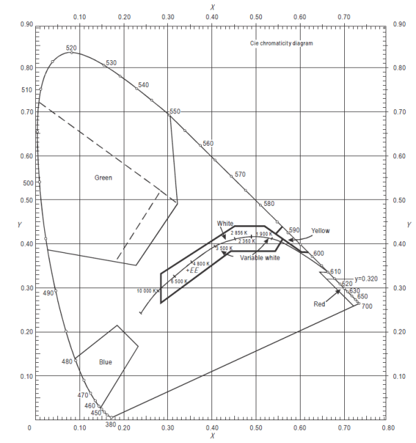
Figure U-1A. Colours for aeronautical ground lights (filament-type lamps)
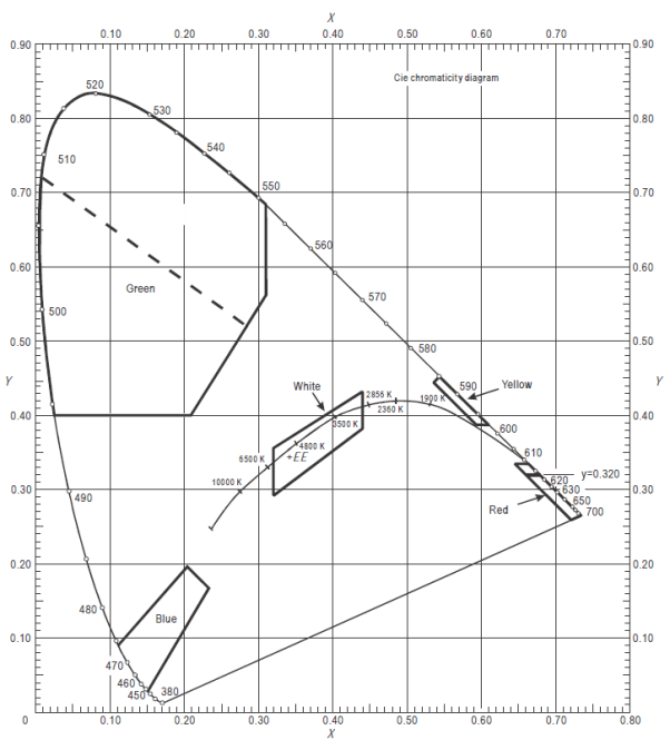
Figure U-1B. Colours for aeronautical ground lights (solid state lighting)
[Issue: ADR-DSN/3]
[Issue: ADR-DSN/4]
GM1 ADR-DSN.U.930 Colours for aeronautical ground lights
ED Decision 2017/021/R
(a) The chromaticity for ground lights with filament-type light sources, where dimming is not required, or where observers with defective colour vision should be able to determine the colour of the light, green signals should be within the following boundaries:
Yellow boundary y = 0.726 – 0.726x
White boundary x = 0.650y
Blue boundary y = 0.390 – 0.171x
(b) Guidance on chromaticity changes resulting from the effect of temperature on filtering elements is given in ICAO Doc 9157, Aerodrome Design Manual, Part 4, Visual Aids.
(c) Where the colour signal is to be seen from long range, the current practice is to use colours within the boundaries specified in paragraph (a) above.
(d) For the chromaticity of ground lights with solid-state light sources, where observers with defective colour vision should be able to determine the colour of the light, green signals should be within the following boundaries:
Yellow boundary y = 0.726 – 0.726x
White boundary x = 0.625y – 0.041
Blue boundary y = 0.400
(e) For the chromaticity of ground lights having a solid state light source, in order to avoid a large variation of shades of green, and if colours within the boundaries below are selected, colours within the boundaries specified in paragraph (d) above should not be used:
Yellow boundary x= 0.310
White boundary x = 0.625y – 0.041
Blue boundary y = 0.726 – 0.726x
(f) Colour measurement for filament-type and solid state-type light sources:
(1) for the outermost isocandela curve, a measurement of colour coordinates should be made and recorded for review and judgement of acceptability; and
(2) certain light units may have an application so that they may be viewed and used by pilots from directions beyond that of the outermost isocandela curve (e.g. stop bar lights at significantly wide runway-holding positions); then an assessment of the actual application should be conducted and, if necessary, a check of colour shift at angular ranges beyond the outermost curve carried out.
[Issue: ADR-DSN/3]
[Issue: ADR-DSN/4]
CS ADR-DSN.U.935 Colours for markings, signs and panels
ED Decision 2022/006/R
(a) The specifications in surface colours given below apply only to freshly coloured surfaces. Colours used for markings, signs, and panels usually change with time and, therefore, require renewal.
(b) The specifications in paragraph (f) below for internally illuminated panels are interim in nature and are based on the CIE specifications for internally illuminated signs. It is intended that these specifications should be reviewed and updated as and when CIE develops specifications for internally illuminated panels.
(c) The chromaticities and luminance factors of ordinary colours, colours of retroreflective materials, and colours of internally illuminated signs and panels should be determined under the following standard conditions:
(1) angle of illumination: 45°;
(2) direction of view: perpendicular to surface; and
(3) illuminant: CIE standard illuminant D65.
(d) The chromaticity and luminance factors of ordinary colours for markings and externally illuminated signs and panels should be within the following boundaries when determined under standard conditions.
CIE Equations (see Figure U-2):
(1) Red
Purple boundary y = 0.345 – 0.051x
White boundary y = 0.910 – x
Orange boundary y = 0.314 + 0.047x
Luminance factor β = 0.07 (minimum)
(2) Orange
Red boundary y = 0.285 + 0.100x
White boundary y = 0.940 – x
Yellow boundary y = 0.250 + 0.220x
Luminance factor β = 0.20 (minimum)
(3) Yellow
Orange boundary y = 0.108 + 0.707x
White boundary y = 0.910 – x
Green boundary y = 1.35x – 0.093
Luminance factor β = 0.45 (minimum)
(4) White
Purple boundary y = 0.010 + x
Blue boundary y = 0.610 – x
Green boundary y = 0.030 + x
Yellow boundary y = 0.710 – x
Luminance factor β = 0.75 (minimum)
(5) Black
Purple boundary y = x – 0.030
Blue boundary y = 0.570 – x
Green boundary y = 0.050 + x
Yellow boundary y = 0.740 – x
Luminance factor β = 0.03 (maximum)
(6) Yellowish green
Green boundary y = 1.317x + 0.4
White boundary y = 0.910 – x
Yellow boundary y = 0.867x + 0.4
(7) Green
Yellow boundary x = 0.313
White boundary y = 0.243 + 0.670x
Blue boundary y = 0.493 – 0.524x
Luminance factor β = 0.10 (minimum)
The small separation between surface red and surface orange is not sufficient to ensure the distinction of these colours when seen separately.
(e) The chromaticity and luminance factors of colours of retroreflective materials for markings, signs, and panels should be within the following boundaries when determined under standard conditions.
CIE Equations (see Figure U-3):
(1) Red
Purple boundary y = 0.345 – 0.051x
White boundary y = 0.910 – x
Orange boundary y = 0.314 + 0.047x
Luminance factor β = 0.03 (minimum)
(2) Orange
Red boundary y = 0.265 + 0.205x
White boundary y = 0.910 – x
Yellow boundary y = 0.207 + 0.390x
Luminance factor β = 0.14 (minimum)
(3) Yellow
Orange boundary y = 0.160 + 0.540x
White boundary y = 0.910 – x
Green boundary y = 1.35x – 0.093
Luminance factor β = 0.16 (minimum)
(4) White
Purple boundary y = x
Blue boundary y = 0.610 – x
Green boundary y = 0.040 + x
Yellow boundary y = 0.710 – x
Luminance factor β = 0.27 (minimum)
(5) Blue
Green boundary y = 0.118 + 0.675x
White boundary y = 0.370 – x
Purple boundary y = 1.65x – 0.187
Luminance factor β = 0.01 (minimum)
(6) Green
Yellow boundary y = 0.711 – 1.22x
White boundary y = 0.243 + 0.670x
Blue boundary y = 0.405 – 0.243x
Luminance factor β = 0.03 (minimum)
(f) The chromaticity and luminance factors of colours for luminescent or internally illuminated signs and panels should be within the following boundaries when determined under standard conditions.
CIE Equations (see Figure U-4):
(1) Red
Purple boundary y = 0.345 – 0.051x
White boundary y = 0.910 – x
Orange boundary y = 0.314 + 0.047x
Luminance factor
(day condition) β = 0.07 (minimum)
Relative luminance
to white (night condition) 5 % (minimum) 20 % (max)
(2) Yellow
Orange boundary y = 0.108 + 0.707x
White boundary y = 0.910 – x
Green boundary y = 1.35x – 0.093
Luminance factor
(day condition) β = 0.45 (minimum)
Relative luminance
to white (night condition) 30 % (minimum) 80 % (max)
(3) White
Purple boundary y = 0.010 + x
Blue boundary y = 0.610 – x
Green boundary y = 0.030 + x
Yellow boundary y = 0.710 – x
Luminance factor
(day condition) β = 0.75 (minimum)
Relative luminance
to white (night conditions) 100 %
(4) Black
Purple boundary y = x – 0.030
Blue boundary y = 0.570 – x
Green boundary y = 0.050 + x
Yellow boundary y = 0.740 – x
Luminance factor
(day condition) β = 0.03 (max)
Relative luminance
to white (night condition) 0 % (minimum) 2 % (maximum)
(5) Green
Yellow boundary x = 0.313
White boundary y = 0.243 + 0.670x
Blue boundary y = 0.493 – 0.524x
Luminance factor
(day conditions) β = 0.10 minimum
Relative luminance
to white (night conditions) 5 % (minimum) 30 % (maximum)
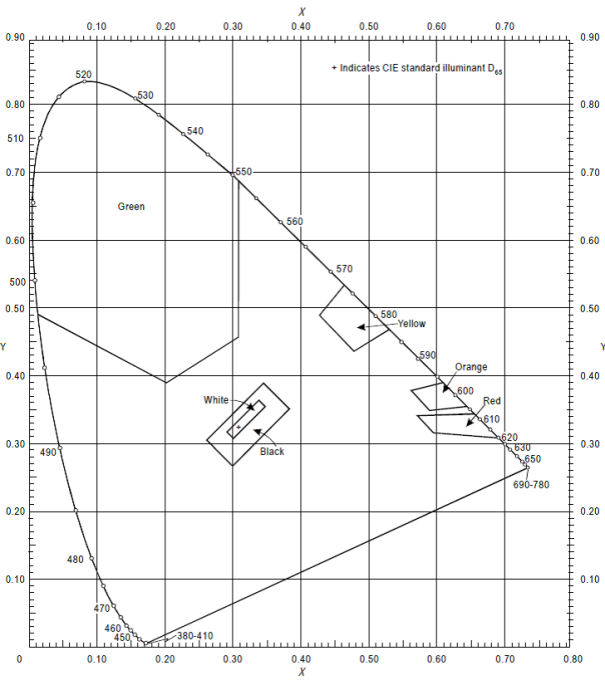
Figure U-2. Ordinary colours for markings and externally illuminated signs and panels
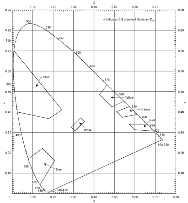
Figure U-3. Colours of retroreflective materials for markings, signs and panels
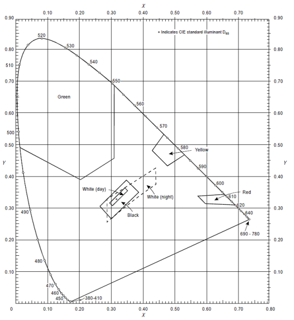
Figure U-4. Colours of luminescent or internally illuminated signs and panels
[Issue: ADR-DSN/3]
[Issue: ADR-DSN/6]
GM1 ADR-DSN.U.935 Colours for markings, signs and panels
ED Decision 2014/013/R
intentionally left blank
CS ADR-DSN.U.940 Aeronautical ground light characteristics
ED Decision 2017/021/R
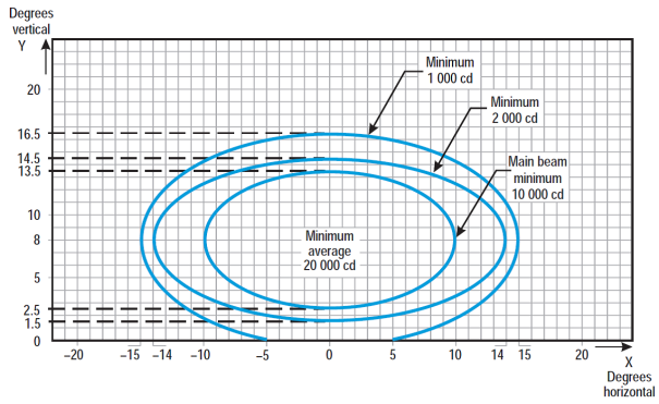
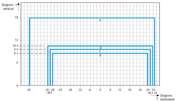
Figure U-5. Isocandela diagram for approach centre line light and crossbars (white light)
Notes:
(a) Curves calculated on formula
|
a |
10 |
14 |
15 |
|
b |
5.5 |
6.5 |
8.5 |
![]()
(b) Vertical setting angles of the lights should be such that the following vertical coverage of the main beam should be met:
|
distance from threshold |
vertical main beam coverage |
|
threshold to 315 m |
0° - 11° |
|
316 m to 475 m |
0.5° - 11.5° |
|
476 m to 640 m |
1.5° - 12.5° |
|
641 m and beyond |
2.5° -13.5° (as illustrated above) |
(c) Lights in crossbars beyond 22.5 m from the centre line should be toed-in 2 degrees. All other lights should be aligned parallel to the centre line of the runway.
(d) See collective notes for Figures U-5 to U-15.
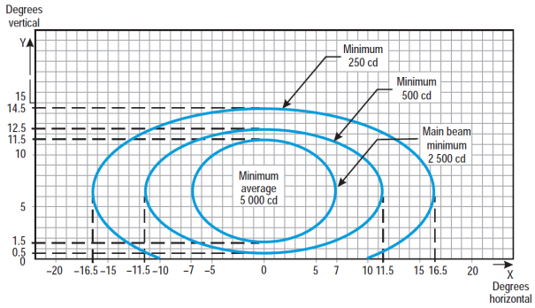
Figure U-6. Isocandela diagram for approach side row light (red light)
Notes:
(a) Curves calculated on formula
|
a |
7.0 |
11.5 |
16.5 |
|
b |
5.0 |
6.0 |
8.0 |
![]()
(b) Toe-in 2 degrees
(c) Vertical setting angles of the lights should be such that the following vertical coverage of the main beam should be met:
|
distance from threshold |
vertical main beam coverage |
|
threshold to 115 m |
0.5° - 10.5° |
|
116 m to 215 m |
1° - 11° |
|
216 m and beyond |
1.5° - 11.5° (as illustrated above) |
(d) See collective notes for Figures U-5 to U-15.
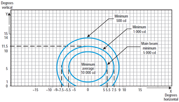
Figure U-7. Isocandela diagram for threshold light (green light)
Notes:
(a) Curves calculated on formula
|
a |
5.5 |
7.5 |
9.0 |
|
b |
4.5 |
6.0 |
8.5 |
![]()
(b) Toe-in 3.5 degrees
(c) See collective notes for Figures U-5 to U-15.
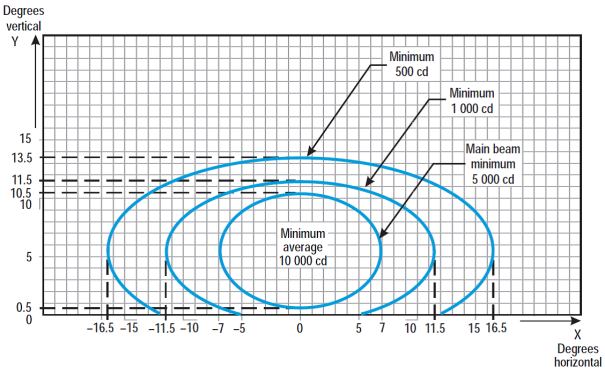
Figure U-8. Isocandela diagram for threshold wing bar light (green light)
Notes:
(a) Curves calculated on formula
|
a |
7.0 |
11.5 |
16.5 |
|
b |
5.0 |
6.0 |
8.0 |
![]()
(b) Toe-in 2 degrees
(c) See collective notes for Figures U-5 to U-15.
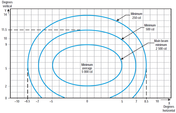
Figure U-9. Isocandela diagram for touchdown zone light (white light)
Notes:
(a) Curves calculated on formula
|
a |
5.0 |
7.0 |
8.5 |
|
b |
3.5 |
6.0 |
8.5 |
![]()
(b) Toe-in 4 degrees
(c) See collective notes for Figures U-5 to U-15.
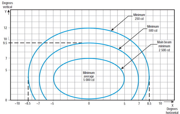
Figure U-10. Isocandela diagram for runway centre line light with 30 m longitudinal spacing (white light) and rapid exit taxiway indicator light (yellow light)
Notes:
(a) Curves calculated on formula
|
a |
5.0 |
7.0 |
8.5 |
|
b |
3.5 |
6.0 |
8.5 |
![]()
(b) For red light, multiply values by 0.15.
(c) For yellow light, multiply values by 0.40.
(d) See collective notes for Figures U-5 to U-15.
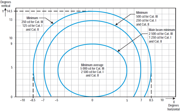
Figure U-11. Isocandela diagram for runway centre line light with 15 m longitudinal spacing (white light) and rapid exit taxiway indicator light (yellow light)
Notes:
(a) Curves calculated on formula
|
a |
5.0 |
7.0 |
8.5 |
|
b |
3.5 |
6.0 |
8.5 |
![]()
(b) For red light, multiply values by 0.15.
(c) For yellow light, multiply values by 0.40.
(d) See collective notes for Figures U-5 to U-15.
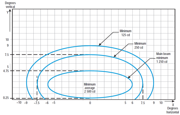
Figure U-12. Isocandela diagram for runway end light (red light)
Notes:
(a) Curves calculated on formula
|
a |
6.0 |
7.5 |
9.0 |
|
b |
2.25 |
5.0 |
6.5 |
![]()
(b) See collective notes for Figures U-5 to U-15.
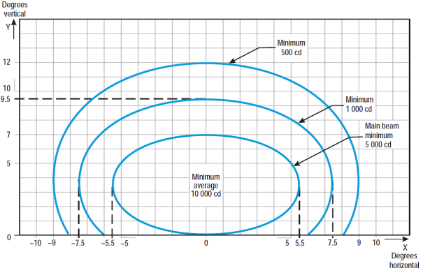
Figure U-13. Isocandela diagram for runway edge light where width of runway is 45 m (white light)
Notes:
(a) Curves calculated on formula
|
a |
5.5 |
7.5 |
9.0 |
|
b |
3.5 |
6.0 |
8.5 |
![]()
(b) Toe-in 3.5 degrees
(c) For red light, multiply values by 0.15.
(d) For yellow light, multiply values by 0.40.
(e) See collective notes for Figures U-5 to U-15.
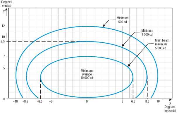
Figure U-14. Isocandela diagram for runway edge light where width of runway is 60 m (white light)
Notes:
(a) Curves calculated on formula
|
a |
6.5 |
8.5 |
10.0 |
|
b |
3.5 |
6.0 |
8.5 |
![]()
(b) Toe-in 4.5 degrees
(c) For red light, multiply values by 0.15.
(d) For yellow light, multiply values by 0.40.
(e) See collective notes for Figures U-5 to U-15.
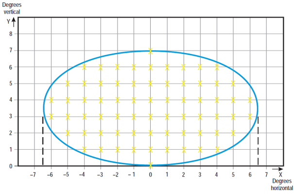
Figure U-15. Grid points to be used for the calculation of average intensity of approach and runway lights
Collective notes to Figures U-5 to U-15
(a) The ellipses in each Figure are symmetrical about the common vertical and horizontal axes.
(b) Figures U-5 to U-14 show the minimum allowable light intensities. The average intensity of the main beam is calculated by establishing grid points as shown in Figure U-15 and using the intensity value measures at all grid points located within and on the perimeter of the ellipse representing the main beam. The average value is the arithmetic average of light intensities measured at all considered grid points.
(c) No deviations are acceptable in the main beam pattern when the lighting fixture is properly aimed.
(d) Average intensity ratio. The ratio between the average intensity within the ellipse defining the main beam of a typical new light and the average light intensity of the main beam of a new runway edge light should be as follows:
|
Figure U-5 |
Approach centre line and crossbars |
1.5 to 2.0 |
(white light) |
|
Figure U-6 |
Approach side row |
0.5 to 1.0 |
(red light) |
|
Figure U-7 |
Threshold |
1.0 to 1.5 |
(green light) |
|
Figure U-8 |
Threshold wing bar |
1.0 to 1.5 |
(green light) |
|
Figure U-9 |
Touchdown zone |
0.5 to 1.0 |
(white light) |
|
Figure U-10 |
Runway centre line (longitudinal spacing 30 m) |
0.5 to 1.0 |
(white light) |
|
Figure U-11 |
Runway centre line (longitudinal spacing 15 m) |
0.5 to 1.0 for CAT III |
(white light) |
|
0.25 to 0.5 for CAT I, II |
(white light) |
||
|
Figure U-12 |
Runway end |
0.25 to 0.5 |
(red light) |
|
Figure U-13 |
Runway edge (45 m runway width) |
1.0 |
(white light) |
|
Figure U-14 |
Runway edge (60 m runway width) |
1.0 |
(white light) |
(e) The beam coverages in the Figures provide the necessary guidance for approaches down to an RVR of the order of 150 m and take-offs down to an RVR of the order of 100 m.
(f) Horizontal angles are measured with respect to the vertical plane through the runway centre line. For lights other than centre line lights, the direction towards the runway centre line is considered positive. Vertical angles are measured with respect to the horizontal plane.
(g) Where, for approach centre line lights and crossbars and for approach side row lights, inset lights are used in lieu of elevated lights, e.g. on a runway with a displaced threshold, the intensity requirements can be met by installing two or three fittings (lower intensity) at each position.
(h) The importance of adequate maintenance cannot be overemphasised. The average intensity should never fall to a value less than 50 % of the value shown in the Figures, and it should be the aim of aerodrome operator to maintain a level of light output close to the specified minimum average intensity.
(i) The light unit should be installed so that the main beam is aligned within one-half degree of the specified.
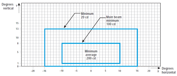
Figure U-16. Isocandela diagram for taxiway centre line (15 m spacing), RELs, no-entry bar, and stop bar lights in straight sections intended for use in runway visual range conditions of less than a value of 350 m where large offsets can occur and for low-intensity runway guard lights, Configuration B
Notes:
(a) These beam coverages allow for displacement of the cockpit from the centre line up to distances of the order of 12 m and are intended for use before and after curves.
(b) See collective notes for Figures U-16 to U-25.
(c) Increased intensities for enhanced rapid exit taxiway centre line lights are four times the respective intensities in the figure (i.e. 800 cd for minimum average main beam).
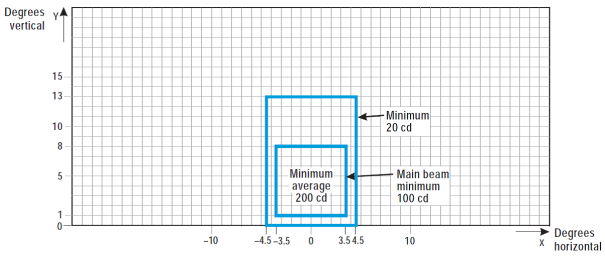
Figure U-17. Isocandela diagram for taxiway centre line (15 m spacing), no-entry bar, and stop bar lights in straight sections intended for use in runway visual range conditions of less than a value of 350 m
Notes:
(a) These beam coverages are generally satisfactory and cater for a normal displacement of the cockpit from the centre line of approximately 3 m.
(b) See collective notes for Figures U-16 to U-25.
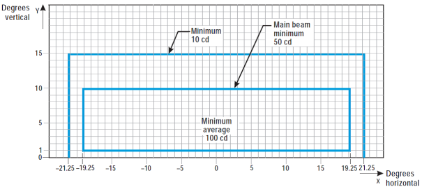
Figure U-18. Isocandela diagram for taxiway centre line (7.5 m spacing), RELs, no-entry bar, and stop bar lights in curved sections intended for use in runway visual range conditions of less than a value of 350 m
Notes:
(a) Lights on curves to be toed-in 15.75 degrees with respect to the tangent of the curve. This does not apply to RELs.
(b) Where provided, increased intensities for RELs should be twice the specified intensities, i.e. minimum 20 cd, main beam minimum 100 cd, and minimum average 200 cd.
(c) See collective notes for Figures U-16 to U-25.
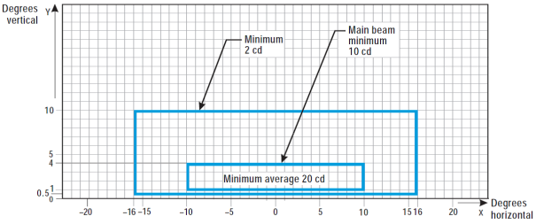
Figure U-19. Isocandela diagram for taxiway centre line (30 m, 60 m spacing), no-entry bar, and stop bar lights in straight sections intended for use in runway visual range conditions of 350 m or greater
Notes:
(a) At locations where high background luminance is usual, and where deterioration of light output resulting from dust, snow, and local contamination is a significant factor, the cd-values should be multiplied by 2.5.
(b) Where omnidirectional lights are used they should comply with the vertical beam requirements in this Figure.
(c) See collective notes for Figures U-16 to U-25.
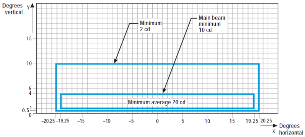
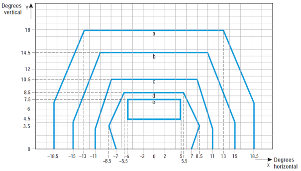
Figure U-20. Isocandela diagram for taxiway centre line (7.5 m, 15 m, 30 m spacing), no-entry bar, and stop bar lights in curved sections intended for use in runway visual range conditions of 350 m or greater
Notes:
(a) Lights on curves to be toed-in 15.75 degrees with respect to the tangent of the curve.
(b) At locations where high background luminance is usual and where deterioration of light output resulting from dust, snow and, local contamination is a significant factor, the cd-values should be multiplied by 2.5.
(c) These beam coverages allow for displacement of the cockpit from the centre line up to distances of the order of 12 m as could occur at the end of curves.
(d) See collective notes for Figures U-16 to U-25.
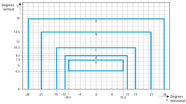
|
Curve |
a |
b |
c |
d |
e |
|
Intensity (cd) |
8 |
20 |
100 |
450 |
1800 |
Figure U-21. Isocandela diagram for high-intensity taxiway centre line (15 m spacing), no-entry bar, and stop bar lights in straight sections intended for use in an advanced surface movement guidance and control system where higher light intensities are required and where large offsets can occur.
Notes:
(a) These beam coverages are generally satisfactory and cater for a normal displacement of the cockpit corresponding to the outer main gear wheel on the taxiway edge.
(b) See collective notes for Figures U-16 to U-25.
|
Curve |
a |
b |
c |
d |
e |
|
Intensity (cd) |
8 |
20 |
100 |
450 |
1800 |
Figure U-22. Isocandela diagram for high-intensity taxiway centre line (15 m spacing), no-entry bar, and stop bar lights in straight sections intended for use in an advanced surface movement guidance and control system where higher light intensities are required
Notes:
(a) These beam coverages are generally satisfactory and cater for a normal displacement of the cockpit corresponding to the outer main gear wheel on the taxiway edge.
(b) See collective notes for Figures U-16 to U-25.
|
Curve |
a |
b |
c |
d |
|
Intensity (cd) |
8 |
100 |
200 |
400 |
Figure U-23. Isocandela diagram for high-intensity taxiway centre line (7.5 m spacing), no-entry bar, and stop bar lights in curved sections intended for use in an advanced surface movement guidance and control system where higher light intensities are required
Notes:
(a) Lights on curves to be toed-in 17 degrees with respect to the tangent of the curve.
(b) See collective notes for Figures U-16 to U-25.
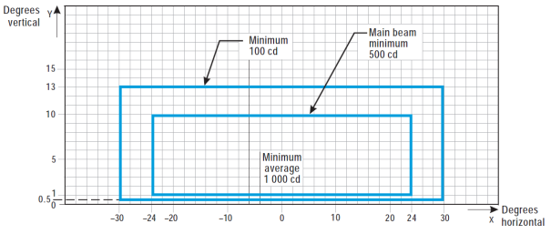
Figure U-24. Isocandela diagram for high-intensity runway guard lights, Configuration B
Notes:
(a) Although the lights flash in normal operation, the light intensity is specified as if the lights were fixed for incandescent lamps.
(b) See collective notes for Figures U-16 to U-25.
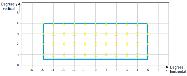
Figure U-25. Grid points to be used for calculation of average intensity of taxiway centre line and stop bar lights
Collective notes to Figures U-16 to U-25:
(a) The intensities specified in Figures U-16 to U-24 are in green and yellow light for taxiway centre line lights, yellow light for runway guard lights, and red light for stop bar lights.
(b) Figures U-16 to U-24 show the minimum allowable light intensities. The average intensity of the main beam is calculated by establishing grid points as shown in Figure U-25, and using the intensity values measured at all grid points located within and on the perimeter of the rectangle representing the main beam. The average value is the arithmetic average of the light intensities measured at all considered grid points.
(c) No deviations are acceptable in the main beam or in the innermost beam as applicable, when the lighting fixture is properly aimed.
(d) Horizontal angles are measured with respect to the vertical plane through the taxiway centre line, except on curves where they are measured with respect to the tangent to the curve.
(e) Vertical angles are measured from the longitudinal slope of the taxiway surface.
(f) The importance of adequate maintenance cannot be overemphasised. The intensity, either average where applicable or as specified on the corresponding isocandela curves, should never fall to a value less than 50 % of the value shown in the figures, and it should be the aim of aerodrome operator to maintain a level of light output close to the specified minimum average intensity.
(g) The light unit should be installed so that the main beam or the innermost beam as applicable, is aligned within one-half degree of the specified requirement.
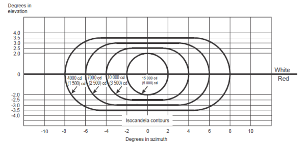
Figure U-26. Light intensity distribution of PAPI and APAPI
Notes:
(a) These curves are for minimum intensities in red light.
(b) The intensity value in the white sector of the beam is no less than 2 and may be as high as 6.5 times the corresponding intensity in the red sector.
(c) The intensity values shown in brackets are for APAPI.
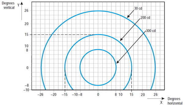
Figure U-27. Isocandela diagram for each light in low-intensity runway guard lights, Configuration A
Notes:
(a) Although the lights flash in normal operation, the light intensity is specified as if the lights were fixed for incandescent lamps.
(b) The intensities specified are in yellow light.
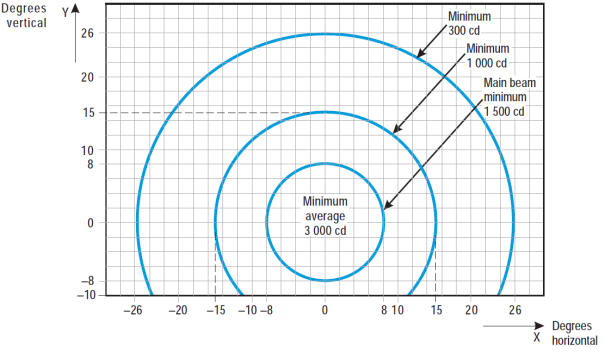
Figure U-28. Isocandela diagram for each light in high-intensity runway guard lights, Configuration A
Notes:
(a) Although the lights flash in normal operation, the light intensity is specified as if the lights were fixed for incandescent lamps.
(b) The intensities specified are in yellow light.
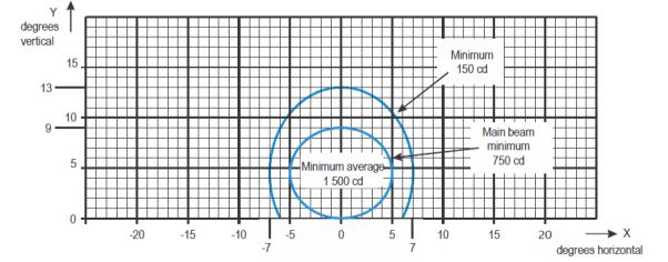
Figure U-29. Isocandela diagram for take-off and hold lights (THL) (red light)
Notes:
(a) Curves calculated on formula
|
a |
5.0 |
7.0 |
|
b |
4.5 |
8.5 |
![]()
(b) See collective notes for Figures U-5 to U-15 and Figure U-29
[Issue: ADR-DSN/3]
[Issue: ADR-DSN/4]
GM1 ADR-DSN.U.940 Aeronautical ground light characteristics
ED Decision 2014/013/R
intentionally left blank