
CS HPT-DSN.E.400 Applicability
ED Decision 2019/012/R
The purpose of the obstacle limitation surfaces is to define the airspace around heliports so as to permit intended helicopter operations to be conducted safely.
CS HPT-DSN.E.410 Approach surface
ED Decision 2019/012/R
(a) Applicability: The purpose of an approach surface is to protect a helicopter during the final approach to the FATO by defining an area that should be kept free from obstacles to protect a helicopter in the final phase of the approach to land manoeuvre.
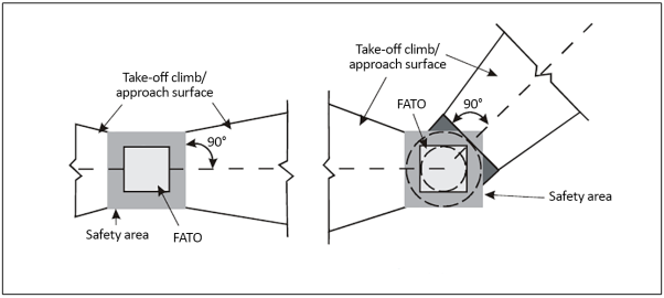
(b) Description: An inclined plane or a combination of planes or, when a turn is involved, a complex surface sloping upwards from the end of the safety area and centred on a line passing through the centre of the FATO (see Figures E-1, E-2, E-3 and E-4 and Table E-1).
(c) Characteristics:
(1) The limits of an approach surface should comprise:
(i) an inner edge horizontal and equal in length to the minimum specified width/diameter of the FATO plus the safety area, perpendicular to the centre line of the approach surface and located at the outer edge of the safety area;
(ii) two side edges originating at the ends of the inner edge diverging uniformly at a specified rate from the vertical plane containing the centre line of the FATO; and
(iii) an outer edge horizontal and perpendicular to the centre line of the approach surface and at a specified height of 152 m (500 ft) above the elevation of the FATO.
(2) The elevation of the inner edge should be the elevation of the FATO at the point on the inner edge that is intersected by the centre line of the approach surface. For heliports intended to be used by helicopters operated in performance class 1, the inclined plane may be raised directly above the FATO.
(3) The slope(s) of the approach surface should be measured in the vertical plane containing the centre line of the surface.
(4) In the case of an approach surface involving a turn, the surface should be a complex surface containing the horizontal normals to its centre line and the slope of the centre line should be the same as that for a straight approach surface (see Figure E-3).
(5) In the case of an approach surface involving a turn, the surface should not contain more than one curved portion.
(6) Where a curved portion of an approach surface is provided, the sum of the radius of the arc defining the centre line of the approach surface and the length of the straight portion originating at the inner edge should not be less than 575 m.
(7) Any variation in the direction of the centre line of an approach surface should be designed so as not to necessitate a turn radius less than 270 m.
|
Note 1 - Dark grey shaded area requires the same characteristics as the safety area |
Note 2 - Angle between take-off climb/ approaches surfaces from centreline to centreline depicted for illustration purposes only Note 3 - Offset take-off climb/approach surface rotated around centre point of FATO |
Figure E-1. Obstacle limitation surfaces — Take-off climb and approach surface
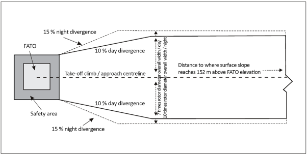
Figure E-2. Take-off climb/approach surface width
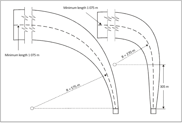
Note 1 - Any combination of curve and straight portion may be established using the following formula: S+R ≥ 575 m and R ≥ 270 m where S = 305 m, where S is the length of the straight portion and R is the radius of turn. Note any combination ≥ 575 m will work.
Note 2 - The minimum length of the centre line of the curve and straight portion is 1 075 m but may be longer depending upon the slope used. See table E-1 for longer lengths.
Note 3 - Helicopter take-off performance is reduced in a curve and as such a straight portion along the take-off climb surface prior to the start of the curve should be considered to allow for acceleration.
Figure E-3. Curved approach and take-off climb surface for all FATOs
|
SURFACE AND DIMENSIONS |
SLOPE DESIGN CATEGORIES |
||
|
A |
B |
C |
|
|
APPROACH AND TAKE-OFF CLIMB SURFACE: |
|
|
|
|
Length of inner edge |
Width of safety area |
Width of safety area |
Width of safety area |
|
Location of inner edge |
Safety area boundary (Clearway boundary if provided) |
Safety area boundary |
Safety area boundary |
|
Divergence: (1st and 2nd section) |
|||
|
Day use only |
10 % |
10 % |
10 % |
|
Night use |
15 % |
15 % |
15 % |
|
First section: |
|||
|
Length |
3 386 m |
245 m |
1 220 m |
|
Slope |
4.5 % (1:22.2) |
8 % (1:12.5) |
12.5 % (1:8) |
|
Outer width |
(b) |
N/A |
(b) |
|
Second section: |
|||
|
Length |
N/A |
830 m |
N/A |
|
Slope |
N/A |
16 % (1:6.25) |
N/A |
|
Outer width |
N/A |
(b) |
N/A |
|
Total length from inner edge (a) |
3 386 m |
1 075 m |
1 220 m |
|
(a) The approach and take-off climb surface lengths of 3 386 m, 1 075 m and 1 220 m associated with the respective slopes, bring the helicopter to 152 m (500 ft) above FATO elevation. (b) 7 rotor diameters overall width for day operations or 10 rotor diameters overall width for night operations. |
|||
|
Note: The slope design categories depicted above represent minimum design slope angles and not operational slopes. Slope category ‘A’ generally corresponds with helicopters operated in performance class 1; slope category ‘B’ generally corresponds with helicopters operated in performance class 3; and slope category ‘C’ generally corresponds with helicopters operated in performance class 2. |
|||
Table E-1. Dimensions and slopes of obstacle limitation surfaces for all visual FATOs
a) Approach and take-off climb surfaces – “A” slope profile – 4.5 % design
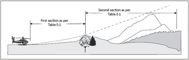
b) Approach and take-off climb surfaces – “B” slope profile – 8 % and 16 % design
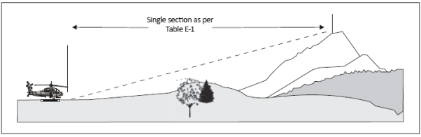
c) Approach and take-off climb surfaces – “C” slope profile – 12.5 % design
Figure E-4. Approach and take-off climb surfaces with different slope design categories
GM1 HPT-DSN.E.410 Approach surface
ED Decision 2019/012/R
(a) Consultations with helicopter operators could assist the aerodrome operator in determining the appropriate slope category to apply according to the heliport environment and the most critical helicopter type for which the heliport is intended.
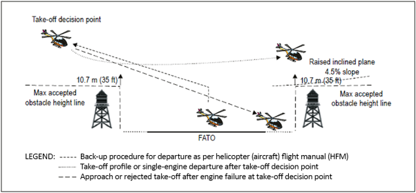
Figure GM1-E-1. Example of raised inclined plane during operations in performance class 1
(b) The example shown in Figure GM1-E-1 does not represent any specific profile, technique or helicopter type and is intended to show a generic example. An approach profile and a back-up procedure for departure profile are depicted. Specific manufacturers operations in performance class 1 may be represented differently in the specific helicopter (aircraft) flight manual (HFM).
(c) The approach/landing profile may not be the reverse of the take-off profile.
(d) Additional safety assessment for obstacles might be required in the area that a back-up procedure is intended. Helicopter performance and the HFM limitations would determine the extent of the assessment required.
(e) For heliports intended to be used by helicopters operated in performance class 2 and 3, it is good practice for the approach paths to be selected so as to permit safe forced landing or one-engine-inoperative landings such that, as a minimum requirement, injury to persons on the ground or water or damage to property are minimised. The most critical helicopter type for which the heliport is intended and the ambient conditions may be factors in determining the suitability of such areas.
(f) The approach and take-off surfaces should be offset from each other ideally by an angle of not less than 135 degrees.
CS HPT-DSN.E.420 Take-off climb surface
ED Decision 2019/012/R
(a) Applicability: The purpose of the take-off climb surface is to protect a helicopter on take-off and during climb-out.
(b) Description: An inclined plane, a combination of planes or, when a turn is involved, a complex surface sloping upwards from the end of the safety area and centred on a line passing through the centre of the FATO (see Figures E-1, E-2, E-3, and E-4, and Table E-1).
(c) Characteristics:
(1) The limits of a take-off climb surface should comprise:
(i) an inner edge horizontal and equal in length to the minimum specified width/diameter of the FATO plus the safety area, perpendicular to the centre line of the take-off climb surface and located at the outer edge of the safety area;
(ii) two side edges originating at the ends of the inner edge and diverging uniformly at a specified rate from the vertical plane containing the centre line of the FATO; and
(iii) an outer edge horizontal and perpendicular to the centre line of the take-off climb surface and at a specified height of 152 m (500 ft) above the elevation of the FATO.
(2) The elevation of the inner edge should be the elevation of the FATO at the point on the inner edge that is intersected by the centre line of the take-off climb surface. For heliports intended to be used by helicopters operated in performance class 1, the inclined plane may be raised directly above the FATO.
(3) Where a clearway is provided the elevation of the inner edge of the take-off climb surface should be located at the outer edge of the clearway at the highest point on the ground based on the centre line of the clearway.
(4) In the case of a straight take-off climb surface, the slope should be measured in the vertical plane containing the centre line of the surface.
(5) In the case of a take-off climb surface involving a turn, the surface should be a complex surface containing the horizontal normals to its centre line and the slope of the centre line should be the same as that for a straight take-off climb surface (see Figure E-3).
(6) In the case of a take-off climb surface involving a turn, the surface should not contain more than one curved portion.
(7) Where a curved portion of a take-off climb surface is provided, the sum of the radius of the arc defining the centre line of the take-off climb surface and the length of the straight portion originating at the inner edge should not be less than 575 m.
(8) Any variation in the direction of the centre line of a take-off climb surface should be designed so as not to necessitate a turn of radius less than 270 m.
GM1 HPT-DSN.E.420 Take-off climb surface
ED Decision 2019/012/R
(a) Helicopter take-off performance is reduced in a curve, so a straight portion along the take-off climb surface prior to the start of the curve allows for acceleration.
(b) For heliports intended to be used by helicopters operated in performance class 2 and 3, it is an operational requirement for departure paths to be selected so as to permit safe forced landings or one-engine-inoperative landings such that injury to persons on the ground or damage to property are minimised. The most critical helicopter type for which the heliport is intended and the ambient conditions may be factors in determining the suitability of such areas.
(c) The approach and take-off surfaces should be offset from each other ideally by an angle of not less than 135 degrees.
CS HPT-DSN.E.430 Obstacle limitation requirements
ED Decision 2019/012/R
(a) General: The following obstacle limitation surfaces should be established for a FATO:
(1) take-off climb surface; and
(2) approach surface.
(b) Characteristics:
(1) The slopes of the obstacle limitation surfaces should not be greater than, and their other dimensions not less than, those specified in Table E-1 and should be located as shown in Figures E-1, E-2 and E-4.
(2) Where a heliport visual approach slope indicator is installed, additional obstacle protection surfaces should be provided, as specified in CS HPT-DSN.F.660, which can be more demanding than the obstacle limitation surfaces prescribed in Table E-1.
(3) For heliports that have an approach/take-off climb surface with a 4.5 per cent slope design, objects can be permitted to penetrate the obstacle limitation surface, if after a safety assessment, it is determined that the object would not adversely affect the safety or significantly affect the regularity of operations of helicopters.
(4) New objects or extensions of existing objects should not be permitted above the approach or take-off climb surfaces except when shielded by an existing immovable object or when after a safety assessment, it is determined that the object would not adversely affect the safety or significantly affect the regularity of operations of helicopters.
(5) Existing objects above the approach and take off climb surfaces should, as far as practicable, be removed except when the object is shielded by an existing immovable object or when after a safety assessment, it is determined that the object would not adversely affect the safety or significantly affect the regularity of operations of helicopters.
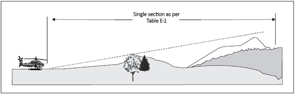
(6) When only a single approach and take-off climb surface is provided, a safety assessment should be undertaken considering as a minimum, the following factors:
(i) the area/terrain over which the flight is being conducted;
(ii) the obstacle environment surrounding the heliport;
(iii) the performance and operating limitations of helicopters intending to use the heliport; and
(iv) the local meteorological conditions including the prevailing winds.