
Filters
AMC1 Article 11 Rules for conducting an operational risk assessment
ED Decision 2025/018/R
SPECIFIC OPERATIONS RISK ASSESSMENT (SORA) (SOURCE: JARUS SORA V2.5)
Edition: September 2025
Section 0 Executive summary
S0.1The SORA approach
The SORA process is intended to provide a risk-proportionate method for determining the evidence and assurance required for an unmanned aircraft system (UAS) to be acceptably safe when operating in the ‘specific’ category of UAS operations as defined in Article 3(b) of Implementing Regulation (EU) 2019/947.
The SORA process provides structure and guidance for both the competent authority and the applicant to support an application to operate a UAS in a given operational environment. The benefit of this process is that both the competent authority and the applicant can allocate their available resources and time proportionally to the risk of the intended UAS operation. After receiving an operational authorisation, the applicant becomes the UAS operator. For the sake of simplicity, the term ‘UAS operator’ is used throughout the rest of this AMC.
The SORA is a holistic safety risk management process used to evaluate the risks related to a given UAS operation and then establish proportionate requirements a UAS operation should comply with to ensure that a target level of safety (TLOS) is met. This TLOS is defined for people and aircraft that are not involved in the UAS operation and is commensurate with the existing level of safety for manned aviation. The TLOS-related values were chosen to ensure that the risk posed by UAS operations to third parties will not be greater than that posed by manned aviation, which are seen as socially acceptable values (see Section 5(f) of the Scoping Paper to AMC RPAS 1309 Issue 214 and Section 1.2.1 of Annex F15 Edition 2.5):
i.for ground risk — fewer than one fatality per million hours (10–6 fatalities per flight hour) (for more details, see Annex F Edition 2.52 Section 1.2.1);
ii.for air risk — fewer than one mid-air collision per 10 million flight hours (10–7 mid-air collisions per flight hour) for operations that are primarily conducted under self-separation and see-and-avoid (primarily in uncontrolled airspace); for operations that are conducted with separation provided by an air navigation service provider (primarily in controlled airspace), the TLOS is one mid-air collision per billion flight hours (10–9 mid-air collisions per flight hour).
The SORA has been developed using assumptions expected to be both credible and conservative across a wide range of UAS operations.
Under the ‘specific’ category, different UAS operations will have different levels of inherent risk and, thus, varying levels of the ability to maintain control of the operation to meet the TLOS will need to be demonstrated. To do this, the SORA has developed the specific assurance and integrity levels (SAIL), which map the maximum allowable loss-of-control rate to operational, organisational, personnel, design and production risk controls that, when implemented correctly at the required level, ensures that an operation meets the TLOS. This means that for a UAS operation conducted in a high-risk environment (e.g. over a large city near an airport) more evidence would need to be provided to the competent authority demonstrating that the operation is safe than for the same UAS operated in a low-risk environment (e.g. at a protected test range and below 30 m).
S0.2The SORA methodology
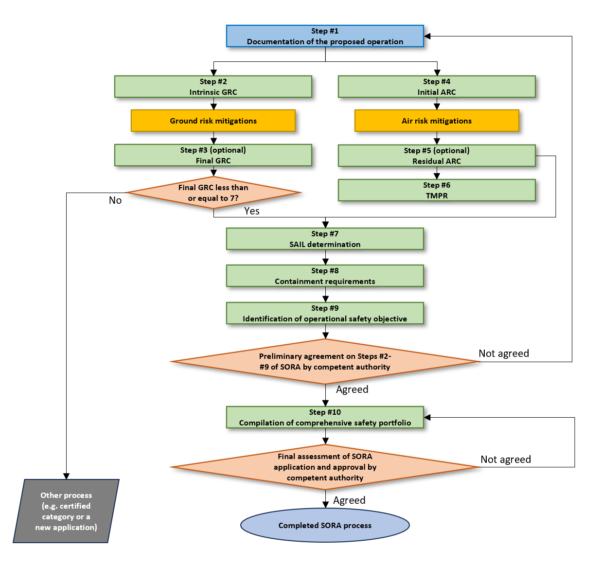
Figure 1 — The SORA process
Note: If UAS operations are conducted across different environments, some steps may need to be repeated for each particular environment (e.g. the operation includes a flight path partially in controlled and partially in uncontrolled airspace; in this case, steps #4 and #5 should be repeated for the two environments).
The SORA methodology consists of ten systematic steps:
Step #1: Documentation of the proposed operation
This is a preparatory step which is intended to ensure the UAS operator has sufficient information to complete Steps #2 to #9 of the SORA process. This information should enable the subsequent steps of the SORA process to be completed successfully.
Step #2: Determination of the intrinsic ground risk class (iGRC)
The iGRC (scaled from 1 to 10) is determined by the UA characteristics (maximum characteristic dimension and maximum speed) as well as the population density at risk in the operational volume and ground risk buffer.
Step #3: Determination of the final ground risk class (GRC) (optional)
The final GRC is determined based on any mitigations put in place, as described in Annex B to this AMC, which may have a significant effect on the likelihood of a fatality after the loss of control of the operation, including:
(i)strategic mitigations intended to reduce the risk before the flight;
(ii)tactical mitigations intended to reduce the risk during the flight;
(iii)mitigations intended to reduce the effect of a ground impact.
A final GRC higher than 7 is outside the scope of the SORA and should be handled in the ‘certified’ category of UAS operations, as defined in Article 6 of Implementing Regulation (EU) 2019/947.
Step #4: Determination of the initial air risk class (iARC)
The determination of the ARC is done in Steps #4 and #5. In Step #4, the iARC is assessed based on an expected generalised encounter rate in the airspace identified in Step #1. The parameters that define the four categories of ARC (a, b, c, d) are the following: whether the airspace is atypical (e.g. segregated), altitude, controlled by air traffic versus uncontrolled, airport versus non-airport environment, and airspace over urban versus rural environments.
Step #5: Application of strategic mitigations to determine the residual air risk class (ARC)
The residual ARC is obtained after applying any relevant strategic mitigations in order to lower the iARC. Two types of strategic mitigations, as described in Annex C, exist in the SORA. Air risk mitigations are either operational restrictions (e.g. boundaries, time of operation) which are controlled by the UAS operators, or by the structure and associated rules of the airspace which is controlled by the relevant authorities (e.g. U-space airspace).
Step #6: Tactical mitigation performance requirements (TMPRs) and robustness levels
Tactical mitigations for the operation are then applied in Step #6 to mitigate any remaining unacceptable residual risk of a mid-air collision with manned air traffic after the strategic mitigations have been applied.
TMPRs address the functions of detect, decide, command, execute and feedback loop (see Annex D to this AMC) for each residual ARC.
Step #7: Determination of the SAIL
A SAIL (scaled from I to VI) is then assigned to the operation described in Step #1 based on the final GRC and residual ARC.
Step #8: Determination of containment requirements
The containment requirements aim to ensure that the TLOS can be met for both ground and air risk in the adjacent ground area.
There are three possible levels of robustness for containment: low, medium and high; each level with a set of safety requirements described in Annex E to this AMC as a function of the UA characteristics, SAIL, average population density in the defined adjacent ground area and the presence of an outdoor assembly of people within 1 km of the outer limit of the operational volume.
Step #9: Identification of operational safety objectives (OSOs)
The SAILs define the level of integrity and assurance (low, medium, high) to be met for each OSO according to the criteria provided in Annex E to this AMC.
For the assigned SAIL, the UAS operator is required to show compliance with each of the 17 OSOs, at the defined robustness level (for lower SAILs, it may not be required to show compliance for some OSOs to the competent authority). The OSOs cover but are not limited to: the UAS designer, UAS operator or other organisations involved in maintenance, related services and training, UAS technical aspects, deterioration of external systems supporting UAS operations, human–machine interface, human error, adverse operating conditions.
Step #10: Comprehensive safety portfolio (CSP)
The CSP is a suite of documents showing compliance with the requirements resulting from the SORA steps for the proposed operation. If the CSP does not provide appropriate evidence as determined by the SORA process at a given SAIL, changes to the proposed operation (e.g. reduction of the intrinsic risk of the operation), additional mitigations, possible UAS design changes, or further analysis/evidence may be needed.
Annex A to this AMC provides guidance and templates on how to provide relevant information to the competent authority as part of the SORA process.
Section 1 Introduction
S.1.1 Preface
The SORA methodology guides both the UAS operator and the competent authority towards the determination of whether a UAS operation can be conducted safely. The document should not be used as a checklist, nor be expected to provide answers to all the potential challenges related to the UAS operation. The SORA is a guide that allows an operator to identify the risk and, if needed, reduce it to an acceptable level by tailoring their mitigations to the intended UAS operation. This involves meeting or exceeding the target level of safety (TLOS) regardless of the complexity of the UAS operation, UA size, or area of operation. The TLOS of operations conducted under the ‘specific’ category covered by the SORA is equivalent to that of the ‘open’ and ‘certified’ categories. For this reason, it does not contain prescriptive requirements but rather safety objectives to be met at various levels of robustness commensurate with the risk of a given operation.
S.1.2Purpose of the document
(a)The purpose of the SORA is to propose a methodology of risk assessment to support an application for authorisation to operate a UAS in the ‘specific’ category.
(b)Due to the operational differences and expected increase in level of risk of the operating environment, the ‘specific’ category cannot automatically take credit for the safety and performance data demonstrated with the large number of UAS operating in the ‘open’ category. Therefore, the SORA provides a consistent approach to assess the additional risks associated with the expanded operations not covered by the ‘open’ category.
(c)This methodology is proposed as an acceptable means to evaluate the safety risks and determine the acceptability of a proposed UAS operation in the ‘specific’ category.
(d)This methodology may be applied where the traditional approach to aircraft certification (approving the design, issuing an airworthiness approval and a type certificate) may not be appropriate and proportionate to the safety risk presented for the intended operation. This methodology may also support activities necessary to determine the associated airworthiness requirements.
(e)The methodology is based on the principle of a holistic safety risk-based assessment model used to evaluate the risks of a given operation. The model considers the most common safety threats associated with a specified hazard, the relevant design, and the proposed operational mitigations for a specific UAS operation. The SORA then helps to evaluate the risks systematically and determine any operational limitation required for its safe operation. This method allows the UAS operator to determine acceptable risk levels and validate that those levels are complied with by the proposed operations. The competent authority may also apply this methodology to gain confidence that the UAS operator can conduct the operation safely.
(f)The methodology, the related processes, and the values proposed in this document are intended to guide a UAS operator when performing a risk assessment of an intended operation to obtain an operational authorisation by the competent authority. At the same time, this material is intended to support the competent authority when assessing the completeness and acceptability of an application for a UAS to be operated in the ‘specific’ category.
S.1.3Applicability
(a)The methodology presented in this document is aimed at evaluating the safety risks involved in the operation of one or multiple UAS16 of any class and size. In the case of multiple simultaneous UA operating relative to each other, such as displays for entertainment, it is recommended to examine common mode failures and adapt the application of the SORA as needed in consultation with the competent authority.
(b)Safety risks associated with collisions between UA and manned aircraft are in the scope of the methodology. The risk of collision between two UA will be addressed in future revisions of the document. It is expected that multiple simultaneous UAS operations and concurrent high-volume operators have a deconfliction strategy for their own UA.
(c)The carriage of people is outside the scope of the SORA. The carriage of dangerous goods (e.g. weapons, munitions of war, explosives, hazardous medical samples) on board the UAS that present additional hazards is excluded from the scope of this methodology and might require additional safety considerations (e.g. demonstration of the ability to contain the dangerous goods). For more information, please refer to GM1 Article 2(11).
(d)Privacy, data protection, liability, insurance, security and environmental protection are excluded from the scope of applicability of this methodology.
(e)In addition to performing the SORA process, the UAS operator should also ensure compliance with all other regulatory frameworks applicable to UAS operations that are not necessarily addressed by the SORA, i.e. the SORA does not preclude any additional regulatory requirements implemented by the competent authority.
(f)The SORA can be used to obtain operational authorisation for UAS operations conducted in multiple locations. In that situation, the UAS operator needs to provide a SORA that is applicable to all these areas to show that the SORA requirements will be met for all flights performed under the operational authorisation obtained. If a UAS operator can demonstrate to have sufficient procedures in place to correctly allocate operational volumes, buffers, adjacent ground areas and airspace volumes, a generic location authorisation could be considered as described in GM2 UAS.SPEC.030(2).
S.1.4SORA documents
The SORA consists of the following parts:
(a)Main Body (AMC1 to Article 11): describing the SORA risk assessment process;
(b)Annex A to AMC1 to Article 11: guidelines for the UAS operator on collecting and presenting system and operation information for a specific UAS operation to the competent authority;
(c)Annex B to AMC1 to Article 11: integrity and assurance levels for the mitigations used to reduce the intrinsic ground risk class (iGRC);
(d)Annex C to AMC1 to Article 11: air risk strategic mitigations;
(e)Annex D to AMC1 to Article 11: air risk tactical mitigations;
(f)Annex E to AMC1 to Article 11: integrity and assurance levels for the operational safety objectives (OSOs);
(g)Annex F Edition 2.517: theoretical basis for ground risk classification and containment requirements;
(h)Annex I to AMC1 to Article 11: glossary.
Section 2 Key concepts and definitions
S.2.1‘Risk’ in the context of the SORA
(a)The definition of ‘risk’ used in the SORA is the combination of the frequency (probability) of an occurrence and its associated level of severity.
(b)The consequence of an occurrence will be designated as a harm of some type.
(c)Many different categories of harm can arise from any given occurrence. This document will focus on occurrences of harm (e.g. UAS crash) that are short-lived and usually give rise to the potential loss of life. Chronic events (e.g. toxic emissions over a period of time) are explicitly excluded from this assessment. The categories of harm in this document involve the potential for:
(i)fatal injuries to third parties on the ground18;
(ii)fatal injuries to third parties in the air.
(d)As the SORA only addresses safety risks, it is acknowledged that the competent authorities, when appropriate, may consider additional categories of harm (e.g. cybersecurity, privacy, disruption of a community, environmental damage, financial loss, etc.) as defined in point 2(c) of Article 12 of Implementing Regulation (EU) 2019/947.
(e)Fatal injury is a well-defined condition and known by competent authorities. Therefore, the risk of under-reporting fatalities is almost non-existent. The quantification of the associated risk of fatality is straightforward. The usual means to measure fatalities are by the number of deaths within a particular operating time interval (e.g. fatal accident rate per million flight hours) or the number of deaths for a specified circumstance (e.g. fatal accident rate per number of take-offs).
(f)Damage to critical infrastructure is a more complex condition and different countries may have differing sensitivities to this harm. Therefore, the quantification of the associated risks may be difficult and subject to national specificities, thus it is not addressed within the SORA and should be subject to a separate risk assessment. This should be done in cooperation with organisations responsible for the infrastructure, as they are most knowledgeable of the threats.
S.2.2The SORA semantic model
(a)The semantic model is a key aspect to understanding the SORA and introduces concepts and common terms for all users of the SORA.
(b)To facilitate effective communication of all aspects of the SORA, the methodology requires standardised use of terminology for phases of operation19, procedures and operational volumes. The semantic model shown in Figure 2 provides a consistent use of terms for all SORA users. Figure 3 provides a graphical representation of the model and a visual reference to further aid the reader in understanding the SORA terminology.
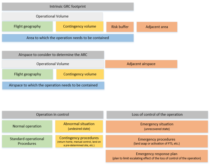
Figure 1 — The SORA semantic model
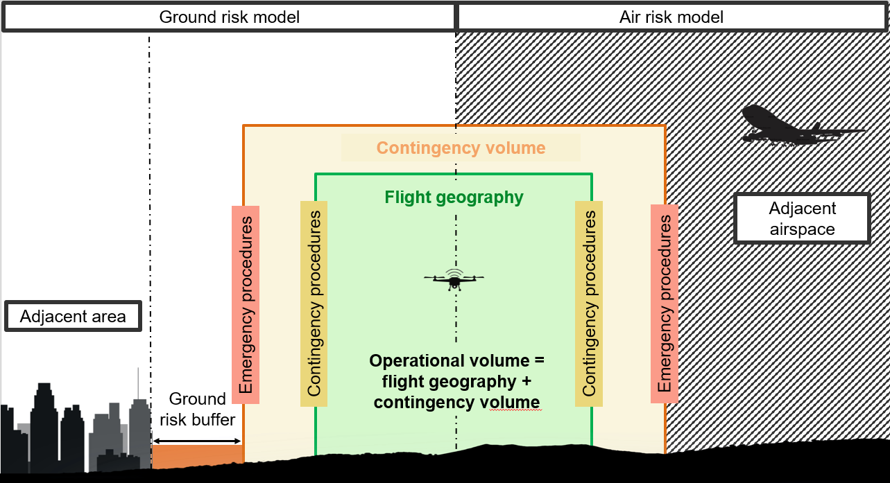
Figure 2 — Graphical representation of the SORA semantic model
(c)The SORA considers two states of the operation: ‘in control’ and ‘loss of control’. The SAIL score of the operation is inversely proportional to the acceptable loss-of-control rate of the operation to meet the OSOs. The higher the SAIL score, the higher the level of integrity and assurance of the OSOs becomes, which should result in a decreased loss-of-control rate for the operation.
S.2.2.1The operational volume
(a)Operational volume is defined as the volume in which the operation is intended to take place safely.
(b)It is made up of the flight geography and the contingency volume.
(c)The operational volume is the basis to determine the air risk class (ARC) of an operation.
(d)The main SORA process is applied to the operational volume and ground risk buffer. To protect the adjacent ground area and airspace, the UAS operation should be contained within the operational volume.
S.2.2.2The flight geography
(a)The flight geography is the volume where the UAS operates in normal operations.
(b)Depending on the type of the operation, the flight geography can be defined as a flight corridor for each planned trajectory, a larger volume to allow for a multitude of similar flights with changing flight paths or a set of different flight volumes fulfilling some specific conditions.
(c)Whenever a particular flight requires the UA to traverse or loiter/hold at a specific point of interest, this point shall be included inside the flight geography. Refer to Chapter A.5 of Annex A to this AMC for additional information.
S.2.2.3The contingency volume
(a)The contingency volume surrounds the flight geography. The outer limit of the contingency volume is equivalent to the outer limit of the operational volume.
(b)Entry into this volume is always considered an abnormal situation and requires the execution of appropriate contingency procedures to return the UA to the flight geography or perform a safe contingency landing. The size of the contingency volume should be determined based on the appropriate contingency procedures.
(c)The outer limit of the contingency volume should include sufficient margins for system and operational errors (refer to the definition of ‘total system error’ in I.139 of Annex I to this AMC).
(d)It should be noted that an abnormal situation may also occur inside the flight geography.
S.2.2.4The ground risk buffer
(a)The ground risk buffer is an area on the ground that surrounds the footprint of the contingency volume.
(b)If the UA exits the contingency volume during a loss of control of the operation, it is expected to end its flight without exceeding the ground risk buffer.
(c)The appropriate size of the ground risk buffer is based on the individual risk of an operation and is driven by the flight characteristics of the UA and the identified containment requirements of the SORA.
(d)The footprint of the operational volume plus the ground risk buffer is the area used to determine the ground risk class (GRC).
S.2.2.5The adjacent ground area
(a)The adjacent ground area represents the ground area adjacent to the ground risk buffer where it is reasonably expected that a UA may crash following a loss-of-control situation resulting in a fly-away.
(b)The lateral inner limit of the adjacent ground area is the outer limit of the ground risk buffer. The lateral outer limit of the adjacent ground area is computed starting from the outer limit of the contingency volume (see Figure 7).
(c)The size of the adjacent ground area depends on the UA performance. UAS operators should not design operational volume areas which are not intended for use but are only there for manipulation of the composition of the adjacent ground area.
S.2.2.6The adjacent airspace
(a)The adjacent airspace corresponds to the airspace where it is reasonably expected that a UA may fly following a loss-of-control situation resulting in a fly-away.
(b)The adjacent airspace is the airspace adjacent to the operational volume.
(c)The lateral outer limit of the adjacent airspace is defined by the lateral outer limit of the adjacent ground area as described in point S.4.8.3(b).
S.2.3States of the operation
S.2.3.1Operation in control
(a)An operation is considered in control when the remote crew can manage the current flight situation, such that no persons on the ground or in the air onboard manned aircraft are put in immediate danger.
(b)This holds true for both normal and abnormal situations; however, the safety margins in the abnormal situation are reduced. In the abnormal state, it is the remote crew’s duty to try to return the operation back to normal state by executing contingency procedures as soon as practically possible.
(c)Normal operation
The UAS operator utilises standard operational procedures consisting of a set of instructions covering policies, procedures and responsibilities set out by the UAS operator that support operational personnel in ground and flight UAS operations safely and consistently.
(d)Abnormal situation
(i)An abnormal situation is an undesired state where it is no longer possible to continue the flight using standard operational procedures, but the safety of the aircraft and of the persons on the ground or in the air is not in immediate danger. In this case, contingency procedures should be applied. Abnormal situations require attention and corrective actions (e.g. reduced engine performance, a system failure that can be managed with the backup or redundant system, issues that do not require an immediate descent, tolerable minor flight control malfunction or navigation equipment malfunction described handled by the UAS flight manual). Abnormal situations should not be confused with emergency situations.
(ii)Contingency procedures are designed to prevent a significant event (e.g. loss of control of the operation) that has an increased likelihood to occur in the future due to the current abnormal state of the operation. These procedures should return the operation to normal state and allow the return to using standard operational procedures or allow the safe cessation of the flight.
S.2.3.2Loss of control of the operation
(a)The loss of control of the operation is a state that corresponds to situations:
(i)whose outcome highly relies on providence; or
(ii)which cannot be handled by a contingency procedure.
(b)In the context of the semantic model, this includes situations where a UA exits the operational volume and potentially operates over or in an area that may be characterised by a different level of ground or air risk.
(c)The loss-of-control state is also entered if a UA does not follow the predefined route and the remote pilot is unable to control it and it crashes, or if an unplanned flight termination sequence is executed, even if this happens inside the operational volume.
(d)Emergency procedures are executed in case of a loss of control of the operation. They are executed by the remote crew and may be supported by automated features of the UAS (or vice versa) and are intended to mitigate the effect of failures that cause or lead to an emergency condition (e.g. flight termination system). Emergency procedures should be activated as soon as the UA reaches the boundaries of the operational volume. However, as soon as the remote crew identifies a failure condition where the control of the UA cannot be recovered through contingency procedures (e.g. loss of propulsion), the remote crew may initiate the emergency procedures when the UAS is in the operation volume. Emergency procedures deal with affecting the UA to either:
(i)return to a state where the operation is ‘in control’; or
(ii)minimise hazards until the flight has ended.
(e)Emergency response plan (ERP)
(i)The ERP deals with the potential hazardous secondary or escalating effects after a loss of control of the operation (e.g. timely intervention of emergency services).
(ii)The ERP is different from the emergency procedures, as it does not deal with the control of the UA.
(iii)The ERP is used for coordinating all the activities needed to respond to incidents and accidents.
(f)Containment is a function that consists of technical and operational mitigations that are meant to contain the flight of the UA within the defined operational volume and ground risk buffer and reduce the likelihood of a loss of control of the operation resulting in a fly-away.
S.2.4Robustness
(a)To properly understand the SORA process, it is important to introduce the key concept of robustness.
(b)Robustness is the term used to describe the combination of two key characteristics of a risk mitigation or operational safety objective: the level of integrity (i.e. how good the mitigation/objective is at reducing the risk), and the level of assurance (i.e. the degree of certainty with which the level of integrity is ensured).
(c)The activities used to substantiate the level of integrity and assurance are detailed in Annexes B, C, D and E to this AMC. These annexes provide either guidance material or reference industry standards and practices where applicable.
(d)Table 1 provides guidance to determine the level of robustness based on the level of integrity and the level of assurance.
Low assurance | Medium assurance | High assurance | |
Low integrity | Low robustness | Low robustness | Low robustness |
Medium integrity | Low robustness | Medium robustness | Medium robustness |
High integrity | Low robustness | Medium robustness | High robustness |
Table 1 — Robustness, integrity and assurance matrix
(e)For example, if an applicant demonstrates a medium level of integrity with a low level of assurance, the overall robustness will be considered low as the robustness is equal to the lowest level of either integrity or assurance.
(f)Any given risk mitigation or operational safety objective will have different requirements for the different levels of robustness. The SORA has three levels of robustness commensurate with the risk: low, medium and high.
(g)Guidance for the level of assurance is provided below. An applicant is required in all cases to achieve the required level of integrity and produce or obtain any necessary evidence required.
(i)For low-level assurance, the applicant declares that the required level of integrity has been achieved. The competent authority may request relevant evidence for review (e.g. during oversight).
(ii)For medium-level assurance, the applicant declares that the required level of integrity has been achieved. The declaration should include a reference to the evidence and the evidence should be provided to the competent authority, unless the applicant uses a means of compliance20 published by EASA. In this case, the applicant may not be required to submit evidence during the application process. However, the competent authority may request relevant evidence for review (e.g. during oversight).
(iii)For high-level assurance, the achievement of the required level of integrity is verified21 to be acceptable by the competent authority or by an entity that is designated22 by the competent authority.
(h)The specific criteria defined in the SORA annexes take precedence over the criteria defined in point (g).
(i)To accommodate national specificities, competent authorities may require different activities to substantiate the level of robustness. National specificities could include nationally sensitive infrastructure, protection of environmental areas, etc., and they are published by MSs as geographical zones according to Article 15 of Implementing Regulation (EU) 2019/947.
S.2.5Roles and responsibilities
While performing an assessment using the SORA process, several key actors might be required to interact in different phases of the process. The key actors to whom SORA is applicable are described in this section.
(a)Applicant — The applicant is the party that produces evidence for compliance with the operational safety objectives or mitigations. It may be the future UAS operator that seeks to obtain an operational authorisation or the organisation that designs or produces the UAS or a training organisation. Supporting material for the assessment may be provided by third parties (e.g. the designer of the UAS or the equipment, U-space service providers, etc.).
(b)UAS operator — The UAS operator is an applicant that has obtained an operational authorisation from the competent authority. The operational authorisation allows the UAS operator to perform a series of flights provided they are performed in accordance with the scope and limitations of the operational authorisation, based on at least the SORA compliance demonstration. The UAS operator is responsible for the safe operation of the UAS. Therefore, the compliant execution of the procedures, training and other applicable programmes as well as the observation of the limitations and other requirements of the applicable concept of operations are the UAS operator’s obligation.
(c)UAS designer and UAS production organisation — The UAS designer and the UAS production organisation is the party that designs and produces the UAS. In some cases, a UAS may be equipped with one or more components (e.g. parachute) designed and produced by an entity other than the UAS designer and installed by a UAS component integrator (that may also be the same entity designing the component or a different entity or the UAS operator itself). It may be expected that sometimes the design and production of the UAS or of the components is carried out by two different organisations. The design and production organisation has unique design evidence (e.g. system performance, system architecture, software/hardware development documentation, test/analysis documentation, etc.) it may choose to share with one or more UAS operators or with the competent authority or with EASA to help substantiate the operator’s SORA safety case. Alternatively, a design and production organisation may use the SORA process to target design objectives for specific or generic operations, tailored to the relevant SAIL. To obtain airworthiness approval(s), these design objectives could be complemented by the use of Light UAS certification specifications (CSs)23 or industry consensus standards if they are found acceptable by EASA. The UAS designer or the UAS production organisation may also be a UAS operator (for example, during a test flight campaign).
(d)Competent authority — The competent authority that is referred to throughout this AMC is the authority designated by the Member State in accordance with Article 17 of Implementing Regulation (EU) 2019/947 to assess the safety case of UAS operations and to issue the operational authorisation in accordance with Article 12 of that Regulation. The competent authority may accept a UAS operator’s submission of an operations manual with an associated SORA-based risk assessment. Through the SORA process, the UAS operator may need to consult with the competent authority to ensure consistent application or interpretation of individual steps. The competent authority should also oversee the UAS operator in accordance with point (h) of Article 18 of Implementing Regulation (EU) 2019/947. When required, the competent authority may decide to make use of ‘recognised entities’ for reviewing supporting evidence for mitigations and operational safety objectives of an application. In this case, the competent authority defines the process and the conditions on how to appoint the ‘recognised entity’ and the competent authority has responsibility when issuing an operational authorisation based on the recommendation provided by the ‘recognised entity’. Alternatively, a competent authority may use a ‘designated entity’, also referred to as ‘qualified entity’, in accordance with Article 69 of Regulation (EU) 2018/1139. In this case, the ‘designated entity’ may be granted the privilege to issue the operational authorisation.
According to Article 77(1) of Regulation (EU) 2018/1139, EASA is the competent authority in the European Union to verify compliance of the UAS design and its components with the applicable rules, while the authority that is designated by the Member State is the competent authority to verify compliance with the operational requirements and compliance of the personnel’s competency with those rules. The following elements are related to UAS design:
—the OSOs marked in Table 14 as those for which the UAS designer is expected to develop evidence;
—M2 mitigation: criterion #1;
—TMPR (design aspects);
—verification of the system to contain the UAS to avoid infringement of the adjacent areas on the ground and/or adjacent airspace in accordance with Step #8 of the SORA process.
If the UAS operation is classified as SAIL V and VI, compliance with the design requirements defined by the SORA (i.e. design-related OSOs, mitigations linked with the design and containment function) should be demonstrated through a type certificate (TC) issued by EASA according to Annex I (Part 21) to Regulation (EU) No 748/201224, as defined in Article 40(1)(d) of Implementing Regulation (EU) 2019/94525. For the OSOs and mitigations, the competent authority may verify their compliance.
If the UAS operation is classified as SAIL IV, compliance with the design-related SORA requirements (i.e. design-related OSOs, mitigations linked with the design and containment function) should be demonstrated through a design verification report (DVR)26 issued by EASA. Evidence of compliance with non-design-related OSOs and mitigations will be provided to the competent authority according to the level of robustness of the OSOs, which will assess them as part of the application for the operational authorisation.
If the UAS operation is classified as SAIL I, II or III, the competent authority may accept, as part of the operational authorisation process, a statement of compliance provided by the designer of the UAS or of a component with all OSOs and mitigations related to design.
Regardless of the SAIL defined at the end of the SORA process, when the claimed level of robustness of the mitigation M2 or of the containment is high, the competent authority should require the UAS operator to use a UAS with a DVR issued by EASA limited to compliance with mitigation M2 and/or the containment requirements27.
(e)Air navigation service provider (ANSP) — The ANSP is the designated provider of air traffic service in a specific area of operation (airspace). The ANSP assesses and/or should be consulted by the UAS operator whether the proposed operation can be safely conducted in the particular airspace the ANSP covers. Whether an ANSP approval would be required may depend on whether the particular proposed operation may be considered as being compliant with the rules of the air (thus being integrated in the airspace), national rules, or should be managed as a contained hazard (for example, through segregation according to the airspace policy of the Member State of operation)28.
(f)U-space service provider (USSP) — USSPs are entities certified according to Implementing Regulation (EU) 2021/66429 that provide services to support the efficient use of airspace as well as the safety of UAS operations. These services may support an operator’s compliance with their safety obligation and risk analysis.
(g)Remote pilot-in-command (RPIC) — The remote pilot that is designated by the UAS operator as being in command of and charged with the safe conduct of the flight. Some UAS operations may require employing more than one remote pilot with different tasks; however, in this case, only one pilot is responsible as RPIC.
UAS designed with a high level of automation may reduce the remote pilot’s workload to the point that operations can be conducted without allowing the intervention of a remote pilot.
(h)Remote crew — The remote crew includes all UAS operator personnel involved in the operation of the UAS, with duties essential to the safe operation of the UAS. The RPIC is part of the remote crew.
(i)Maintenance staff — Ground personnel in charge of maintaining the UAS before and after the flight in accordance with the UAS maintenance instructions.
Section 3 The SORA walk-through
This section provides a description for UAS operators of whether the SORA process applies to their operations and how to complete the required SORA steps.
S.3.1Introduction to the SORA walk-through
(a)This section relates to how the SORA process is described in the document. The intent is to provide both the UAS operators and the competent authorities with clear guidance in terms of what is expected from the SORA process.
(b)The following headers are applied:
(i)Outcome: is the result achieved when the task has been completed. All outcomes are summarised in the comprehensive safety portfolio (CSP).
(ii)Task description: is a recommendation to be followed by UAS operators when completing the SORA process.
(iii)Instructions: is material provided to UAS operators to better identify and understand the steps contained in the task description.
S.3.2Before starting the SORA process
S.3.2.1Outcome
UAS operators will determine whether they should carry out the SORA process.
S.3.2.2Task description
(a)Before starting the SORA process, the following should be verified:
(i)whether the UAS operator uses a tethered aircraft for which Implementing Regulation (EU) 2019/947 does not apply30;
(ii)whether the intended UAS operation falls under the ‘open’ category;
(iii)whether the intended UAS operation is covered by a standard scenario (STS) as defined by Appendix 1 to Implementing Regulation (EU) 2019/947 and the UAS bears an appropriate class identification label;
(iv)whether the UAS operation is covered by one of the PDRAs published by EASA as AMC to Article 11 to Implementing Regulation (EU) 2019/947;
(v)whether the operation involves the transport of people or the transport of dangerous goods posing a high risk to third parties31; in these cases, the operation falls under the ‘certified’ category;
(vi)whether the operation is subject to any local no-go criteria established by the competent authority (e.g. local conditions published by the competent authority of the State of operation).
(b)If none of the above applies, the SORA process should be applied.
S.3.3The phases of the SORA process
(a)As part of the SORA process, it is critical to review the steps and validate the assumptions and derivations made throughout this process. The SORA process can be split into two phases (see Figure 4):
(i)Phase 1 (Step #1 to Step #9) focuses on the derivation of safety requirements and proposed means of compliance; and
(ii)Phase 2 (Step #10) focuses on compliance with the derived safety requirements from Phase 1.
(b)Upon completing Phase 1, it is advisable for the UAS operator to obtain confirmation from the competent authority regarding the correctness of the process conducted thus far. The phases ensure there is a review of the first-phase outputs for the UAS operator to determine whether any adjustments to the proposed operation are required before undertaking the second phase. This approach should minimise unnecessary iterations in the operational procedures, remote crew requirements, and system(s) design in the proposed operations and mitigations32.
(c)An additional benefit of the two phases is that they provide an opportunity for the UAS operator to engage with the competent authority. This is intended to support reaching a preliminary agreement that Phase 1 has been undertaken correctly, and that the derived requirements and proposed means of compliance for Phase 2 are appropriate.
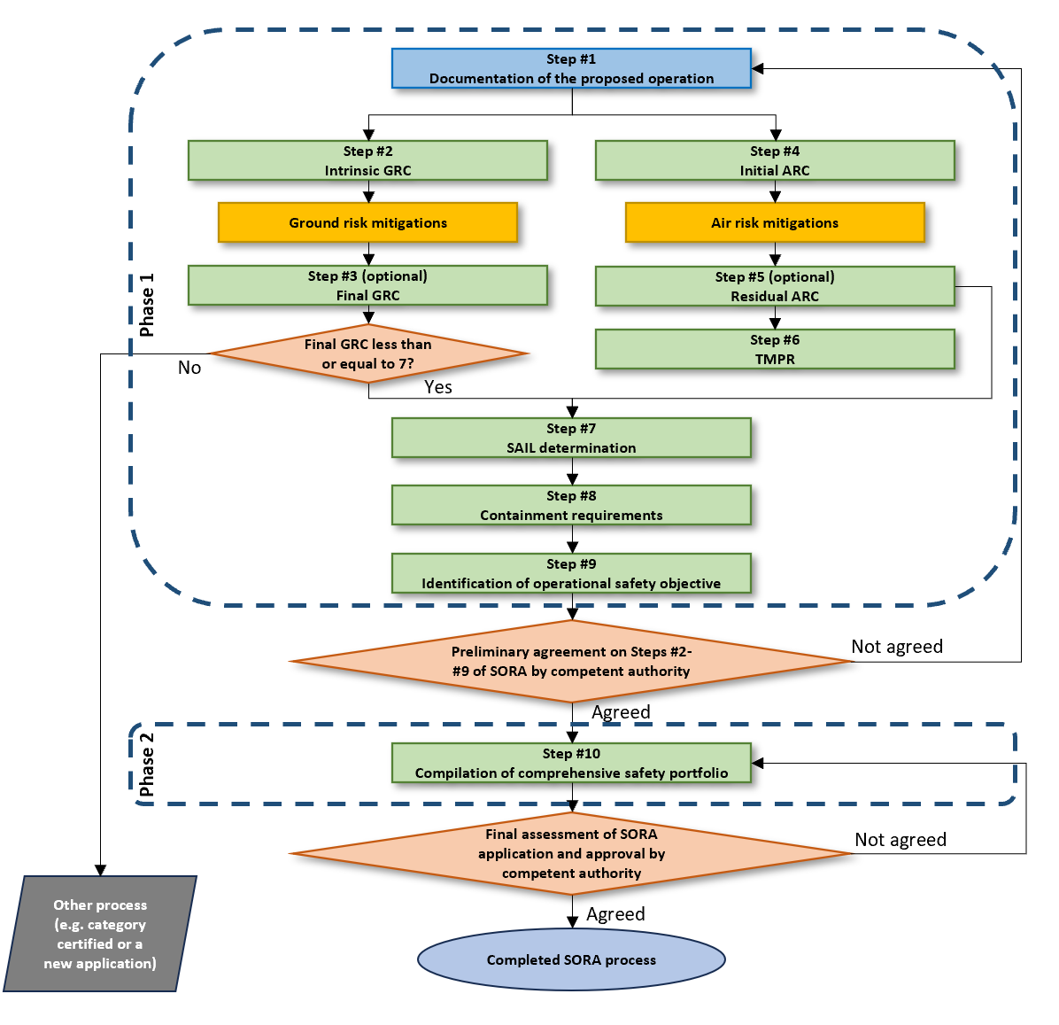
Figure 3 — The phases of the SORA process
S.3.3.1Phase 1 (Derivation of requirements)
(a)The purpose of Phase 1 is to derive all relevant safety requirements based on the proposed operation(s) which should result in a document suite that sufficiently describes the proposed operation(s). This should include the relevant information, safety claims and derived requirements of Step #1 to Step #9. The UAS operator should collect explanations, but not the entire justification, of the means by which the UAS operator will demonstrate compliance with any safety claims. This can assist both the UAS operator and the competent authority in ensuring that any means of compliance proposed is/are valid and will result in satisfying the safety claims. This may take the form of an initial compliance matrix (an example is provided in Chapter A.4 of Annex A to this AMC).
(b)The results of Phase 1 may be the basis for the competent authority to conduct a preliminary evaluation. The competent authority may or may not be able to provide its formal agreement until final compliance evidence (covered in Phase 2) is submitted and reviewed.
(c)It is recommended that the UAS operator contact the competent authority as early as possible in order to present the available information and reach a common initial understanding and in-principle agreement on the safety claims, in particular the final GRC, residual ARC, and SAIL.
S.3.3.2Phase 2 (Compliance with requirements)
(a)Phase 2 occurs after the completion of Step #9. This phase is a final set of iterations to complete the SORA process. This should result in a SORA comprehensive safety portfolio (CSP), which collects the work done in all previous steps of the SORA into a comprehensive, including evidence showing compliance with the SORA requirements.
(b)If the SORA process is completed correctly, the CSP should provide all the necessary claims, arguments and evidence to support the assessment and approval of the proposed operation(s).
Section 4 The SORA process
S.4.1Step #1 — Documentation of the proposed operation
S.4.1.1Introduction
Step #1 provides an opportunity for the UAS operator to collect and present contextual information about the proposed operation and the intended safety claims made during Phase 1 of the SORA process.
S.4.1.2Outcome
A sufficiently detailed operational concept that allows the UAS operator to continue through the SORA process.
S.4.1.3Task description
(a)Compilation of operational, technical and organisational information. Such information may include:
(i)maps, figures, diagrams and other information detailing the operational volume, the ground risk buffers, the adjacent ground area and the adjacent airspace to facilitate the determination of:
(A)the intrinsic GRC (i.e. population density maps, information on land use),
(B)the initial ARC (i.e. information on airspace use, aerodromes, and airspace charts), and
(C)the adjacent ground areas;
(ii)information about the operational, technical and organisational elements of:
(A)the intended operation and functions during flight, including intended flight profiles, states and modes that provide for safety throughout the nominal, contingency and emergency phases of flight,
(B)any ground and air risk mitigations (strategic and tactical) used to reduce the intrinsic ground risk or the initial air risk.
(b)A description of the contingency volume and ground risk buffers, and how they were determined.
(c)The UAS operator may use Chapter A.3 of Annex A to this AMC to gain an understanding of the type of data that needs to be presented, and any other information that supports the risk assessment, to the competent authority.
S.4.2Step #2 — Determination of the intrinsic ground risk class (iGRC)
S.4.2.1Introduction
(a)In this step, the UAS operator is required to assess the intrinsic ground risk of the operational volume and the ground risk buffer.
(b)No ground risk mitigations will be applied at this step; this may be completed in Step #3.
S.4.2.2Outcome
Calculation and documentation of the iGRC.
S.4.2.3Task description
iGRC footprint
(a)Identify the maximum characteristic dimension and the maximum speed of the UA.
(b)Identify the iGRC footprint:
(i)identify the flight geography;
(ii)calculate the contingency volume;
(iii)calculate the initial ground risk buffer (the final ground risk buffer calculation will be completed in Step #8).
(c)Identify the highest population density within the iGRC footprint.
(d)Identify the iGRC of the footprint using Table 2 for fixed-wing aircraft, rotorcraft-helicopters, rotorcraft-gyroplanes, VTOL-capable aircraft (including multirotors)33.
UAS iGRC | ||||||
Maximum UA characteristic dimension | 1 m | 3 m | 8 m | 20 m | 40 m | |
Maximum speed | 25 m/s | 35 m/s | 75 m/s | 120 m/s | 200 m/s | |
Maximum iGRC population density (people/km2) | Controlled ground area | 1 | 1 | 2 | 3 | 3 |
< 5 | 2 | 3 | 4 | 5 | 6 | |
< 50 | 3 | 4 | 5 | 6 | 7 | |
< 500 | 4 | 5 | 6 | 7 | 8 | |
< 5 000 | 5 | 6 | 7 | 8 | 9 | |
< 50 000 | 6 | 7 | 8 | 9 | 10 | |
> 50 000 | 7 | 8 | Not part of SORA | |||
—A single UA with a take-off mass less than or equal to 250 g and having a maximum speed less than or equal to 25 m/s is considered to have an iGRC of 1 regardless of population density, unless operating over assemblies of people34. —A UA that is not expected to penetrate a standard dwelling will get a –1 GRC reduction in Step #3 from the M1(A) sheltering mitigation when not flying over large outdoor assemblies of people and most of the people overflown are protected by adequate structures; see Annex B of this AMC for additional details. | ||||||
Table 1 — Intrinsic ground risk class (GRC) determination
(e)For UA with a maximum characteristic dimension greater than 40 m, the iGRC should be calculated following the guidance in Appendices A and B to Annex F Edition 2.535.
S.4.2.4Instructions
UA characteristics
(a)For maximum UA characteristic dimension examples, refer to the definition of ‘UA characteristic dimensions’ in I.141 of Annex I to this AMC.
(b)Maximum speed
(i)The maximum speed is conservatively defined as the maximum possible commanded airspeed of the UA, as defined by the UAS designer.
(ii)This is not the flight-specific maximum commanded airspeed of the UA as reducing the flight airspeed may not necessarily reduce the impact area36. Mitigations that limit airspeed below the maximum speed value during an impact can be considered in Step #3, referring to Annex B to AMC1 Article 11.
iGRC Footprint
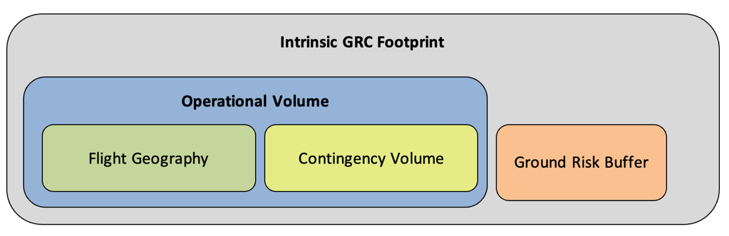
Figure 4 — Visualisation of the iGRC footprint
(c)The UAS operator should have defined the area at risk when conducting the operation. This is defined as the iGRC footprint. It is composed of the operational volume plus the ground risk buffer as shown in Figure 5 above.
(d)The operational volume is composed of the flight geography and the contingency volume (refer to Sections S.2.2.1, S.2.2.2 and S.2.2.3 respectively for additional information). To determine the operational volume, the UAS operator should consider the position-keeping capabilities of the UAS in 4D space (latitude, longitude, height and time). In particular, the accuracy of the navigation solution, the flight technical error of the UAS, the path definition error (e.g. map error) and latencies should be considered when determining the operational volume.
(e)The iGRC footprint is used to determine the population density. It is expected that for many flights the iGRC footprint may cover segments with different population densities. The segment with the highest population density should be used when determining the iGRC.
Identification of the iGRC
(a)The iGRC is found at the intersection of the applicable maximum population density and the rightmost column matching both criteria, the maximum UA characteristic dimension and the maximum speed in Table 2.
(b)The UAS operator may provide substantiation to the competent authority for a different iGRC. See Appendix A of Annex F Edition 2.537 for further guidance.
(c)UAS operations that do not have a corresponding iGRC (i.e. grey cells on the table) are outside the scope of the SORA methodology. In this case, UAS operators should consider the ‘certified’ category.
(d)If population density values are not available or not accurate, the UAS operator may use qualitative descriptors for the iGRC table; the following approximations may be used as guidance:
Quantitative population value (people/km2) | Qualitative descriptors | Area description |
Controlled ground area | Controlled ground / Extremely remote | Areas that are controlled where uninvolved people are not allowed to enter. Refer to point (21) of Article 2 of Implementing Regulation (EU) 2019/947 and related GM1. |
< 5 | Remote | Areas where people may be, such as forests, deserts, large farm parcels, etc. Areas where there is approximately one small building every km2. |
< 50 | Lightly populated | Areas of small farms. Residential areas with very large lots (~ 4 acres or 16 000 m2). |
< 500 | Sparsely populated / Residential lightly populated | Areas comprised of homes and small businesses with large lot sizes (~1 acre or 4 000 m2). |
< 5 000 | Suburban / | Areas of single-family homes on small lots, apartment complexes, commercial buildings, etc. Can contain multistorey buildings, but generally most should be below 3–4 stories. |
< 50 000 | High-density metropolitan | Areas of mostly large multistorey buildings. The downtown area of most cities. Areas of dense skyscrapers. |
> 50 000 | Assemblies of people | Refer to point (3) of Article 2 of Implementing Regulation (EU) 2019/947 and related GM1. |
Table 2 — Correspondence between quantitative and qualitative assessment of the iGRC
Ground risk buffer
(a)An appropriate initial ground risk buffer should be defined considering the principles outlined in criterion #3 of Section E.4 of Annex E of this AMC:
(i)with the 1-to-1 principle38; or
(ii)a different ground risk buffer value may be proposed by the UAS operator using the principles outlined in Section 4, criterion #3 of Annex E of this AMC.
(b)Cases where the final ground risk buffer may be different than the initial one could include:
(i)medium and high level of containment39;
(ii)use of ground risk mitigations, such as a parachute.
Controlled ground area
(a)A controlled ground area is defined as the intended UAS operational area where only involved persons (if any) are present.
(b)Controlled ground areas are a way to strategically mitigate the ground risk; the assurance that there will be no uninvolved persons in the iGRC footprint is under the full responsibility of the UAS operator. The competent authority may request evidence of how the UAS operator will ensure control of the ground area during operation.
Non-typical cases
(a)There are certain cases, for example aircraft whose maximum characteristic dimension and maximum speed differ significantly from the selected column, which may have a significant effect on the iGRC. Such cases may not be well represented in the iGRC table and may lead to an increase or decrease in the iGRC. See Section 1.8 of Annex F Edition 2.540 for further guidance.
(b)A UAS operator may consider that the iGRC is too conservative for its UA. Therefore, a UAS operator may decide to calculate the iGRC by applying the mathematical model defined in Section 1.8 of Annex F Edition 2.526. The UAS operator should choose the column that matches the critical area calculated for the UA that is used, as identified in Table B.8 of Annex B to this AMC. An automatic tool to calculate the critical area of a UA is available on the EASA website41.
Information on population density
(a)Determining the population density to calculate the iGRC in Step #2 should be done using maps with appropriate grid size based on the intended operation. Competent authorities should designate specific maps to be used for determining population densities.
(b)If there are no available population density maps acceptable to the competent authority, the qualitative population density descriptors (see Table 3) may be used to estimate the population density band in the operational volume and the ground risk buffer. Alternatively, the competent authority may require, or permit, UAS operators to provide appropriate population density maps. Table 4 below presents the suggested optimal grid size for different maximum heights of the operational volume.
Max. height (AGL) of the operational volume | Suggested optimal grid size (metre × metre) | |
Feet | Metres | |
500 | 152 | 200 × 200 |
1 000 | 305 | 400 × 400 |
2 500 | 762 | 1 000 × 1 000 |
5 000 | 1 524 | 2 000 × 2 000 |
10 000 | 3 048 | 4 000 × 4 000 |
20 000 | 6 096 | 5 000 × 5 000 |
60 000 | 18 288 | 10 000 × 10 000 |
Table 4 — Suggested grid size for population density maps
(c)The authority-designated map should be at the suggested optimal grid size. If mapping products do not exist at the suggested optimal grid size, the competent authority should use the closest grid size available. If the closest grid size available is smaller than the suggested optimal grid size, then the map should be smoothed to the suggested optimal grid size.
(d)If the UAS operator identifies inaccuracies in the designated static population density map, it can provide alternative data (for example, by using other mapping products, satellite imagery, on-site inspections, local knowledge of the area, etc.) that demonstrates the correction in the estimated average population density of the area. If accepted by the competent authority, the UAS operator may use the alternative data to determine the iGRC. Use of time-based restriction arguments (e.g. flying at night) for the reduction of the number of people at risk on the ground are addressed in SORA Step #3.
(e)Additional information may be found in Section 3.2 of Annex F Edition 2.542.
S.4.3Step #3 — Final ground risk class (GRC) determination (optional)
S.4.3.1Introduction
(a)The intrinsic risk of a person being struck by a UA during the loss of control of the operation can be reduced by means of acceptable mitigations.
(b)In this step, the UAS operator may identify ground risk mitigations and reduce the GRC of the operation.
S.4.3.2Outcome
(a)Identification of the mitigations applied to reduce the iGRC for the iGRC footprint.
(b)Identification of the applicable mitigations.
(c)Determination of the final GRC by subtracting the credit derived by the mitigations from the iGRC.
(d)Collection of information and references used to substantiate the application of the ground risk mitigation(s).
S.4.3.3Task description
(a)Identify the applicable mitigations listed in Table 5 that could lower the iGRC of the iGRC footprint. All mitigations should be applied in numerical sequence.
| Level of robustness | ||
Mitigations for ground risk | Low | Medium | High |
M1(A) — Strategic mitigations — Sheltering | –1 | –2 | n/a |
M1(B) — Strategic mitigations — Operational restrictions | n/a | –1 | –243 |
M1(C) — Tactical mitigations — Ground observation | –1 | n/a | n/a |
M2 — Effects of UA impact dynamics are reduced | n/a | –1 | –2 |
Table 5 — Mitigations for the determination of the final GRC
(b)Identify in Annex B to AMC1 Article 11 the requirements to be complied with in order to receive appropriate credit for the mitigation.
(c)If an M2 mitigation that affects the UA’s descent behaviour is used, assess whether the size of the ground risk buffer defined in Step #2 is still valid.
(d)Determine the final GRC by applying the appropriate correction to the iGRC.
S.4.3.4Instructions
Ground risk mitigations
(a)Step #3 is optional.
(b)The mitigations used to modify the iGRC have a direct effect on the safety objectives associated with an operation. Therefore, it is important to ensure their robustness. This has particular relevance for technical mitigations (e.g. parachute).
(c)The final GRC determination is based on the availability and correct application of the mitigations to the operation. Table 5 provides a list of potential mitigations and the associated relative correction factor. All mitigations should be applied in numeric sequence to perform the assessment. Annex B to this AMC provides additional details on the robustness of each mitigation. Competent authorities may define or accept additional mitigations and the relative correction factors.
(d)A quantitative approach to mitigations allows a reduction in the iGRC by 1 point if the mitigation reduces the population at risk to the next lowest iGRC population band. This is in most cases approximately a factor of 10 (90 % reduction) compared to the risk that is assessed before mitigations are applied. Such quantitative criteria should be used to validate the risk reduction that is claimed when applying Annex B to this AMC.
(e)In rare situations, iGRC reductions greater than the ones shown in Table 5 may be possible. Refer to Annex B to this AMC for further guidance.
(f)When applying all the M1 mitigations, the final GRC cannot be reduced to a value lower than the lowest value in the applicable column in Table 2. This is because it is not possible to reduce the number of people at risk below that of a controlled ground area.
(g)If the mitigation influences the descent behaviour of the UA, for example by using a parachute, the ground risk buffer size should be redefined using the updated assumptions including the effects of the mitigations.
(h)Additional information may be found in Chapter A.3 of Annex A to this AMC regarding guidance on presenting the data that supplements the risk assessment to the competent authority.
What if the final GRC is greater than 7?
If the final GRC is greater than 7, the operation is considered to pose a greater risk than the SORA is designed to support. The UAS operator may consider other options such as using the ‘certified’ category or changing the characteristics of the UAS operation in Step #1 (as stated in Figure 1).
S.4.4 Step #4 — Determination of the initial air risk class (iARC)
S.4.4.1Introduction to the air risk assessment process
(a)The SORA uses the operational airspace defined in Step #1 as the baseline to evaluate the intrinsic risk of mid-air collision with manned aircraft and for determining the iARC. The iARC may be modified (lowered) by applying strategic and tactical mitigations. An example of strategic mitigations to reduce mid-air collision risk may be by operating during certain times or within certain boundaries. After applying strategic mitigations, any residual mid-air collision risk is addressed by means of tactical mitigations.
(b)Tactical mitigations take the form of detect-and-avoid systems or alternative collaborative means, such as ADS-B, systems transmitting on the SRD 860 frequency band, U-space services44 or operational procedures. Depending on the residual mid-air collision risk, the tactical mitigation performance requirement(s) may vary.
(c)As part of the SORA process, the UAS operator should cooperate with the relevant service provider (e.g. ANSP or U-space service provider) for the airspace it intends to operate and obtain the necessary authorisations. Additionally, generic local authorisations or local procedures allowing access to a certain portion of airspace may be used if available. The competent authority or the ANSP may impose additional strategic or tactical mitigations on airspace authorisations, taking into account uncertainties relating to UA reliability, conspicuity, and other factors.
(d)The SORA recommends that, irrespective of the results of the risk assessment, the operator pay particular attention to all features that may increase the detectability of the UA in airspace. Therefore, technical solutions that improve the electronic conspicuousness or detectability of the UAS are recommended.
S.4.4.2Outcome
(a)Identification of the risk of mid-air collision between the UA and a manned aircraft.
(b)Documentation of information and references used to determine the iARC of the operational volume.
S.4.4.3Task description
Operational volume
(a)Identify the vertical limit of the operational volume:
(i)identify the vertical limit of the flight geography;
(ii)identify and document the contingency procedures in case the UA exceeds the height of the flight geography;
(iii)evaluate the maximum height the UA will travel above the limit of the flight geography when applying the contingency procedures before it enters again in the flight geography.
(b)Check whether there are official airspace collision risk maps available. The competent authority or the ANSP may elect to directly map the airspace collision risks using airspace characterisation studies. These maps would directly show the initial/residual air risk class (ARC) for a particular airspace. If the competent authority, the ANSP or the U-space service provider provides an air collision risk map (static or dynamic), the UAS operator should use that service to determine the initial/residual ARC and go directly to Section S.4.5 ‘Application of strategic mitigations’ to reduce the iARC, provided that a further reduction is still possible.
(c)If point (b) is not applicable, identify the iARC of the operational volume using the decision tree in Figure 6.
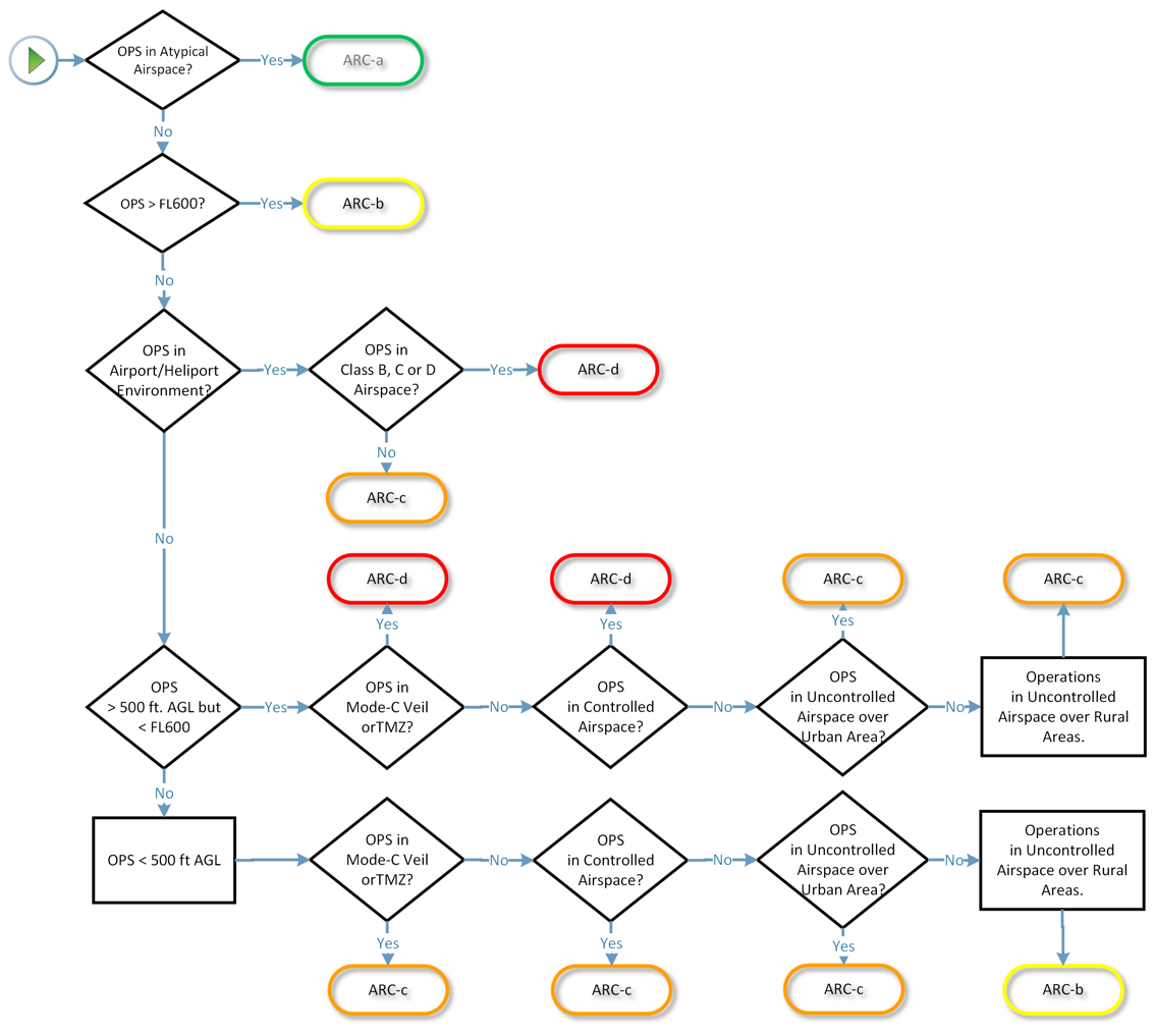
Figure 5 — ARC assignment process
S.4.4.4Instructions
Identification of the iARC
(a)As seen in Figure 6, the airspace is categorised into 12 aggregated collision risk categories. These categories are characterised by altitude, controlled versus uncontrolled airspace, airport/heliport versus non-airport/non-heliport environments, airspace over urban versus rural areas, and lastly atypical (e.g. segregated) versus typical airspace. The categories correspond to the airspace encounter classes (AECs), which provide a further qualitative delineation of non-mitigated collision risk that is elaborated in Annex C to this AMC.
(b)During a UAS operation, the operational volume may span many different airspace environments. The UAS operator should conduct an air risk assessment for the entire range of the operational volume. An example scenario of operations in multiple airspace environments is provided at the end of Annex C to this AMC.
(c)The ARC is a qualitative classification of the rate at which a UAS would typically encounter a manned aircraft within that volume of airspace. The ARC is an initial assignment of the aggregated collision risk for the airspace before mitigations are applied. The actual collision risk for a specific local operational volume could be much different and can be addressed in the application of strategic mitigations to reduce the ARC section (this step is optional; see Step #5 in Section S.4.5).
(d)Although the non-mitigated risk captured by the initial ARC is conservative, there may be situations where that conservative assessment may not suffice. It is important that both the competent authority and the operator take great care to understand the operational volume and under what circumstances the definitions in Figure 6 could be invalidated. In some situations, the competent authority may raise the operational volume’s initial ARC to a level which is higher than that indicated in Figure 6. The ANSP should be consulted to assure that the assumptions related to the operational volume are accurate.
(e)The competent authority may designate parts of its airspace as atypical. ARC-b, ARC-c and ARC-d generally define airspace with an increasing risk of collision between a UAS and manned aircraft.
Identification of the vertical limit of the operational volume
(a)The vertical limit of the flight geography is the maximum height where the UA is planned to operate in normal conditions.
(b)On top of the flight geography, the UAS operator should identify the extent of the contingency volume as the maximum height the UA will travel when applying the contingency procedures.
Atypical air environment
(a)An atypical air environment (leading to ARC-a classification) is defined as airspace where the risk of collision between a UAS and manned aircraft is acceptably low without the application of any tactical mitigations. This is usually the case when it can be generally expected that no manned aircraft use the airspace volume that is intended for the operation.
(b)Examples may include operation in reserved or restricted airspace (e.g. by means of a temporary segregated airspace), or operation at very low altitudes (including in close proximity to obstacles) in those areas where manned aircraft generally do not operate45.
S.4.5 Step #5 — Application of strategic mitigations to determine residual ARC (optional)
S.4.5.1Introduction
(a)The ARC is a qualitative classification of the rate at which a UA would encounter a manned aircraft in a given airspace environment. However, it is recognised that the operational volume may have a collision risk that differs from the iARC assigned.
(b)If the UAS operator considers that the iARC assigned is too high for the condition in the local operational volume, then refer to Annex C to this AMC for the ARC reduction process.
(c)If the UAS operator considers that the iARC assignment is correct for the condition in the local operational volume, then that iARC becomes the residual ARC.
S.4.5.2Outcome
(a)Identification of the strategic mitigations applied to reduce the iARC of the operational volume.
(b)Identification of the residual ARC.
(c)Documentation of information and references used to support the application of strategic mitigations.
S.4.5.3Task description
(a)Identify the applicable strategic mitigations listed in Section 5 of Annex C to this AMC.
(b)Identify the residual ARC of the operational volume following the process listed in Section 6 of Annex C to this AMC.
(c)Refer to Chapter A.3 of Annex A to this AMC for further guidance on how to present the data that supplements the risk assessment to the authority.
(d)If flying in VLOS, consider the additional guidance below.
S.4.5.4Instructions
Application of strategic mitigations
For VLOS operations, or for BVLOS operations where the remote pilot is supported by one or multiple airspace observers (located in a way that the UA is always at a VLOS distance from the remote pilot or from one airspace observer that is able to scan the sky and communicate in real time with the remote pilot informing them of possible other manned or unmanned aircraft flying in the area of operation46), the initial ARC can be reduced by one class. In these conditions, the crew is assumed to have the ability to assess other aircraft activity in the airspace concerned and therefore is able to lower the encounter rate by applying this mitigation both before and during the operation. The mitigation cannot be used to reduce the ARC to ARC-a. In ARC-d environments, agreement with ATC may be required47.
S.4.6Step #6 — Tactical mitigation performance requirement (TMPR) and robustness levels
S.4.6.1Introduction
Tactical mitigations are applied to mitigate any residual risk of a mid-air collision in order to achieve the applicable airspace safety objective.
S.4.6.2Outcome
(a)Identification of the applicable TMPR and corresponding level of robustness.
(b)Collection of information and references to be used to support compliance with the TMPR.
S.4.6.3Task description
Identify whether flying in VLOS, BVLOS or BVLOS with AOs.
VLOS operations or BVLOS with airspace observers (AOs)
(a)Develop and document a VLOS deconfliction scheme, in which it is explained which methods will be used for detection; and
(b)Define the associated criteria applied for the decision to avoid incoming traffic. If the remote pilot relies on AOs for detection, the use of phraseology will have to be described as well.
BVLOS operations
(a)Identify the applicable TMPR level deriving it from the residual ARC using Table 6.
(b)Identify the applicable TMPR according to Section 5 of Annex D to this AMC.
Refer to Chapter A.3 of Annex A to this AMC for further guidance on how to present the data that supplements the risk assessment to the authority.
Residual ARC | TMPR and corresponding level of robustness |
ARC-d | High |
ARC-c | Medium |
ARC-b | Low |
ARC-a | No requirement |
Table 6 — Tactical mitigation performance requirements (TMPR) and assignment of the TMPR level of robustness
S.4.6.4Instructions
Application of tactical mitigations
Tactical mitigations will take the form of either ‘see and avoid’ (i.e. operations in VLOS) or may require a system which provides an alternate means of achieving the applicable airspace safety objective (operation using a detect-and-avoid (DAA) system or multiple DAA systems). Annex D to AMC1 Article 11 provides the method for applying tactical mitigations.
VLOS operations or BVLOS with airspace observers (AOs)
(a)VLOS operations or BVLOS with AOs are considered an acceptable tactical mitigation for collision risk for all ARC levels.
(b)Notwithstanding the above, the operator is advised to consider additional means to increase situational awareness with regard to air traffic operating in the vicinity of the operational volume.
(c)In the case of multiple flight segments, those segments flown in VLOS or in BVLOS with AOs do not have to meet the TMPR nor the TMPR robustness requirements, whereas those flown in BVLOS do need to meet the TMPR and the TMPR robustness requirements.
(d)In general, the VLOS requirements are applicable when one or more airspace observers are employed. In this case, additional requirements beyond VLOS should be proposed, including the definition of procedures and phraseology. The communication latency between the remote pilot and the airspace observer(s) should be less than 15 seconds.
(e)For BVLOS operations with AOs, it is assumed that an airspace observer is not able to detect traffic beyond 2 NM (approximately 3,7 km). (Note that the 2 NM range is not a fixed value and may largely depend on atmospheric conditions, aircraft size, geometry, closing rate, etc.) Therefore, the operator may have to adjust the operation and/or the procedures accordingly.
Tactical mitigation performance requirement (TMPR) levels
(a)High TMPR (ARC-d): The ARC-d level is assigned to airspace where either the manned aircraft encounter rate is high and/or the available strategic mitigations are low. Therefore, the resulting residual collision risk is high and the TMPR level is also high. In such airspace, the UA may be operating in integrated airspace (e.g. integrated with manned aircraft) and will have to comply with the operating rules and procedures applicable to that airspace, without reducing existing capacity, decreasing safety, negatively impacting current operations with manned aircraft, or increasing the risk to airspace users or persons and property on the ground. These are the same requirements as for the integration of comparable new and novel technologies in manned aviation. The performance level(s) of those tactical mitigations and/or the required variety of tactical mitigations is generally higher than for the other ARCs. If operations in this airspace are conducted more routinely, the competent authority is expected to require the operator to comply with the recognised DAA system standards (e.g. those developed by RTCA SC-228 and/or EUROCAE WG-105).
(b)Medium TMPR (ARC-c): A medium TMPR will be required for operations in airspace with a moderate likelihood of encountering manned aircraft and/or where the available strategic mitigations have medium robustness. Operations with a medium TMPR will likely be supported by systems currently used in aviation to aid the remote pilot in detecting other manned aircraft or by systems which are designed to support aviation and which are built to a corresponding level of robustness. Traffic avoidance manoeuvres for a medium TMPR could be more advanced than for a low TMPR.
(c)Low TMPR (ARC-b): A low TMPR will be required for operations in airspace where the likelihood of encountering a manned aircraft is low but not negligible and/or where strategic mitigations address most of the risk and the resulting residual collision risk is low. Operations with a low TMPR are supported by technologies that are designed to aid the remote pilot in detecting other traffic, but which may be built to lesser standards. For example, for operations below 500 ft AGL, the traffic avoidance manoeuvres are expected to mostly be based on a rapid descent to an altitude where manned aircraft are not expected to ever operate.
(d)No TMPR (ARC-a): This is airspace where the manned aircraft encounter rate is expected to be extremely low and, therefore, there is no need for a TMPR. It is defined as airspace where the risk of collision between a UA and manned aircraft is acceptable without the addition of any tactical mitigation. An example of this may be UAS flight operations in some parts of northern Sweden where the manned aircraft density is so low that the airspace safety threshold could be met without any tactical mitigation.
(e)Annex D to this AMC provides information on how to satisfy the TMPR based on the available tactical mitigations and the TMPR level of robustness.
Guidance on airspace/operational requirements
(a)Modifications to the initial and subsequent approvals may be required by the competent authority or the ANSP should safety and operational issues arise.
(b)The operator and the competent authority need to be aware that ARCs are a generalised qualitative classification of collision risks. Local circumstances could invalidate the aircraft density assumptions of the SORA, for example with special events. It is important that both the competent authority and the operator fully understand the airspace and air traffic flows, and develop a system which can alert operators to changes to the airspace on a local level. This will allow the operator to safely address the increased risks associated with these events.
(c)There are many airspace, operational and equipment requirements which have a direct impact on the collision risk of all aircraft that operate in a particular airspace volume. Some of these requirements are general and apply to all airspace volumes, while some are local and are required only for a particular airspace volume. The SORA cannot possibly cover all the possible requirements required by the competent authority for all conditions in which the operator may wish to operate. The UAS operator and the competent authority need to work closely together to define and address these additional requirements.
(d)The SORA process should not be used to support UAS operations in a given airspace volume without the UAS being equipped with the required equipment for operations in that airspace volume (e.g. equipment required to ensure interoperability with other airspace users). In these cases, specific exemptions may be granted by the competent authority. Those exemptions are outside the scope of the SORA.
(e)Operations in controlled airspace, in an airport/heliport environment or in a Transponder Mandatory Zone (TMZ) will likely require prior approval from the ANSP. The UAS operator should ensure that it coordinates with the relevant ANSP/authority prior to commencing operations in these environments.
S.4.7Step #7 — Determination of the specific assurance and integrity level (SAIL)
S.4.7.1Introduction
(a)The SAIL parameter consolidates the ground and air risk analyses and drives the required activities.
(b)The SAIL represents the level of confidence that the UAS operation will remain in control.
S.4.7.2Outcome
Identification of the SAIL.
S.4.7.3Task description
Identify the SAIL associated with the proposed operation deriving it from the final GRC and the residual ARC using Table 7.
SAIL determination | ||||
Residual ARC | ||||
Final GRC | a | b | c | d |
≤2 | I | II | IV | VI |
3 | II | II | IV | VI |
4 | III | III | IV | VI |
5 | IV | IV | IV | VI |
6 | V | V | V | VI |
7 | VI | VI | VI | VI |
>7 | Operation classified in the ‘certified’ category | |||
Table 3 — SAIL determination
S.4.7.4Instructions
(a)The level of confidence that the UAS operation will remain in control is represented by the SAIL.
(b)The SAIL is not quantitative but instead corresponds to:
(i)the level of the OSO robustness to be complied with (see Table 14);
(ii)the description of activities that might support compliance with the OSOs; and
(iii)the evidence that indicates the OSOs have been satisfied.
S.4.8Step #8 — Determination of the containment requirements
S.4.8.1Introduction
(a)The containment requirements ensure that the target level of safety can be met for both ground and air risk in the adjacent ground area.
(b)The containment requirements are derived from the difference between the final ground risk level in the operational volume plus the ground risk buffer and the final ground risk level in the adjacent ground area.
(c)There are three possible levels of robustness for containment: ‘low’, ‘medium’ and ‘high’, each with a set of safety requirements described in Annex E to this AMC.
S.4.8.2Outcome
(a)A set of operational limitations for the population in the adjacent ground area.
(b)A derived level of robustness for containment.
S.4.8.3Task description
(a)If the UA has a take-off mass of less than 250 g, apply low containment with no required operational limitations for the population in the adjacent ground area and go to Step #9. Otherwise, apply point (b).
(b)Determine the size and the population characteristics of the adjacent ground area:
(i)calculate the size of the adjacent ground area for the operation; the lateral outer limit of the adjacent ground area is calculated from the operational volume as the distance flown by the UA in 3 minutes at maximum speed:
(A)if the distance is less than 5 km, use 5 km;
(B)if the distance is between 5 and 35 km, use the distance calculated;
(C)if the distance is greater than 35 km, use 35 km;
(ii)calculate the average population density between the outer limit of the ground risk buffer and the outer limit of the adjacent ground area;
(iii)develop procedures to assess the potential presence of outdoor assemblies of people, during the time when the flight takes place, within 1 km of the outer limit of the operational volume.
(c)Determine a set of operational limitations appropriate for the UAS operation using the columns in Tables 8 to 13.
(i)Choose an operational limitation for the acceptable average population density in the established adjacent ground area.
(ii)Choose an operational limitation for the acceptable size of assemblies of people within 1 km surrounding the operational volume.
(d)Use Tables 8 to 13 to identify the required containment robustness level based on the characteristic dimension of the UA and the SAIL of the operation, considering the most stringent between the value of the average population density and the outdoor assembly of people.
1 m UA (< 25 m/s) Sheltering assumed applicable for the UA in the adjacent ground area48 | |||
Average population density allowed | No upper limit | < 50 000 people/km2 | |
Outdoor assemblies allowed within 1 km of the operational volume | > 400k | Assemblies of 40k to 400k | Assemblies of < 40k |
SAIL |
|
|
|
I & II | High | Medium | Low |
III | Medium | Low | Low |
IV, V -& VI | Low | Low | Low |
Table 8 — Containment requirements for a UA up to 1 m UA with shelter assumption
3 m UA (< 35 m/s) Shelter assumed applicable for the UA in the adjacent ground area32 | ||||
Average population density allowed | No upper limit | < 50 000 people/km2 | < 5 000 | |
Outdoor assemblies allowed within 1 km of the operational volume | > 400k | Assemblies of 40k to 400k | Assemblies of < 40k people | |
SAIL |
|
|
|
|
I & II | Out of scope | High | Medium | Low |
III | Out of scope | Medium | Low | Low |
IV | Medium | Low | Low | Low |
V & VI | Low | Low | Low | Low |
Table 9 — Containment requirements for a UA up to 3 m with shelter assumption
3 m UA (< 35 m/s) Shelter assumed not applicable for the UA in the adjacent ground area | ||||
Average population density allowed | No upper limit | < 50 000 | < 5 000 | < 500 |
Outdoor assemblies allowed within 1 km of the operational volume | > 400k | Assemblies of 40k to 400k | Assemblies of < 40k people | |
SAIL |
|
|
|
|
I & II | Out of scope | High | Medium | Low |
III | Out of scope | Medium | Low | Low |
IV | Medium | Low | Low | Low |
V & VI | Low | Low | Low | Low |
Table 10 — Containment requirements for a UA up to 3 m without shelter assumption
8 m UA (< 75 m/s) Sheltering assumed not applicable for the UA in the adjacent ground area | |||||
Average population density allowed | No upper limit | < 50 000 people/km2 | < 5 000 people/km2 | < 500 people/km2 | < 50 |
Outdoor assemblies allowed within 1 km of the operational volume | > 400k | Assemblies of 40k to 400k | Assemblies of < 40k | ||
SAIL |
|
|
|
|
|
I & II | Out of scope | Out of scope | High | Medium | Low |
III | Out of scope | Out of scope | Medium | Low | Low |
IV | Out of scope | Medium | Low | Low | Low |
V | Medium | Low | Low | Low | Low |
VI | Low | Low | Low | Low | Low |
Table 11 — Containment requirements for a UA up to 8 m
20 m UA (< 120 m/s) Sheltering assumed not applicable for the UA in the adjacent ground area | |||||
Average population density allowed | No upper limit | < 50 000 people/km2 | < 5 000 people/km2 | < 500 people/km2 | < 50 |
Outdoor assemblies allowed within 1 km of the operational volume | > 400k | Assemblies of 40k to 400k | Assemblies of < 40k | ||
SAIL |
|
|
|
|
|
I & II | Out of scope | Out of scope | Out of scope | High | Medium |
III | Out of scope | Out of scope | Out of scope | Medium | Low |
IV | Out of scope | Out of scope | Medium | Low | Low |
V | Out of scope | Medium | Low | Low | Low |
VI | Medium | Low | Low | Low | Low |
Table 12 — Containment requirements for a UA up to 20 m
Sheltering assumed not applicable for the UA in the adjacent ground area | |||||
Average population density allowed | No upper limit | < 50 000 people/km2 | < 5 000 people/km2 | < 500 | < 50 |
Outdoor assemblies allowed within 1 km of the operational volume | > 400k | Assemblies of 40k to 400k | Assemblies of < 40k | ||
SAIL |
|
|
|
|
|
I & II | Out of scope | Out of scope | Out of scope | Out of scope | High |
III | Out of scope | Out of scope | Out of scope | Out of scope | Medium |
IV | Out of scope | Out of scope | Out of scope | Medium | Low |
V | Out of scope | Out of scope | Medium | Low | Low |
VI | Out of scope | Medium | Low | Low | Low |
Table 13 — Containment requirements for a UA up to 40 m
(e)Ensure the operation complies with the containment requirements listed in Annex E Section 4.
S.4.8.4Instructions
Refer to Chapter A.3 of Annex A to this AMC for further guidance on how to present the data that supplements the risk assessment to the competent authority.
Adjacent ground area
(a)The adjacent ground area represents the ground area adjacent to the ground risk buffer where it is reasonably expected that a UA may crash after a loss-of-control situation resulting in a fly-away.
(b)The operator is not approved to plan flights in this area, and it should only be overflown unintentionally in the event of a loss of control that results in a fly-away.
(c)As regards the situation in point (b), the direction and duration of the fly-away is assumed to be random, thus the average population density of the adjacent ground area is used, instead of the maximum as is done in Step #2.
(d)Conservative simplifications for calculating the average population density may be used by the operator when compliance with the operational limitations can be assured.
Calculating the size of the adjacent ground area
The diagram below in Figure 7 depicts how to determine the size of the adjacent ground area.
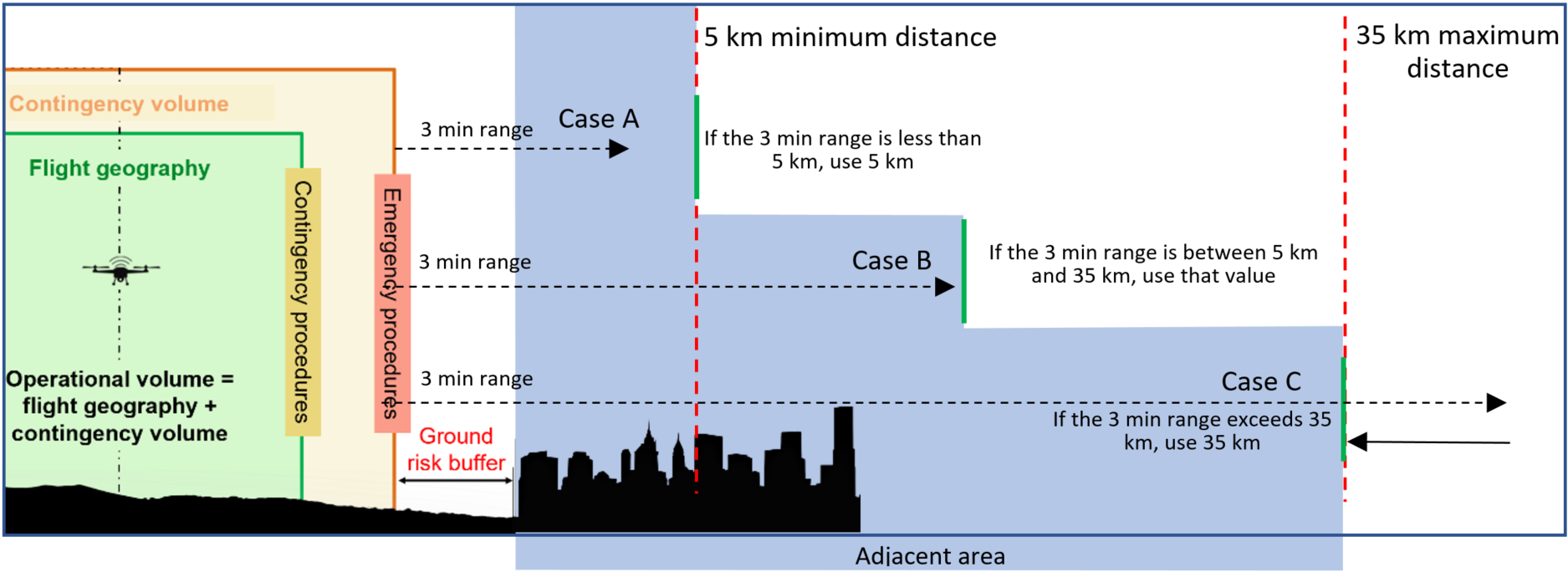
Figure 6 — Lateral limits — Adjacent ground area
If the ground risk buffer is larger than the adjacent ground area, then the assessment of the adjacent ground area is not required.
Adjacent ground area containment requirements
(a)When using Tables 8 to 13 to identify the required containment robustness level of the operation:
(i)select the correct table based on the maximum characteristic dimensions of the UA used in Step #2;
(A)for a 3 m UA determine whether sheltering can be applied in the adjacent ground area, using similar considerations applied in Step #3;
(B)if sheltering applies for a UA greater than 3 m, the operator may use Annex F Edition 2.549 to apply the credit and determine the appropriate containment requirements;
(ii)identify the correct row based on the SAIL found in Step #7;
(iii)identify the appropriate column to derive the containment level of robustness based on the adjacent ground area population density;
(iv)if the results are ‘out of scope’, the operation cannot be conducted in the ‘specific’ category; in this case, adjusting the location of the operation or an increase of the SAIL of the operation could be considered.
(b)Example: An operation uses a SAIL III 2.5 m UA with a maximum speed of 30 m/s, sheltering is applicable, the outer limit of the adjacent ground area is 5.4 km from the boundary of the operational volume. An assessment of the adjacent ground area shows no large outdoor assemblies of people within 1 km and such area spans mostly rural and suburban areas, expecting an average population density between 1–4k people/km2. This results in low containment requirements. If the UAS operator decides to use a UA with low containment, the operator should document the operational limitations for the low containment SAIL III UA:
(i)no assemblies of people > 40k within 1 km of the operational volume;
(ii)the adjacent ground area (5.4 km from the operational volume) average population density should not exceed 50 000 people/km2.
Operational limitations regarding adjacent ground area
(a)The UAS operator should define operational limitations that have to be adhered to when planning the operational volume for a flight operation.
(b)The UAS operator should have a procedure to identify and take into account scheduled outdoor assemblies of people in excess of the operational limitations within 1 km of the outer limit of the operational volume. The values for the size of assemblies of people are to be understood as rough order of magnitude guidelines since measuring the actual values is not practical.
(c)If the ground risk buffer size exceeds 1 km, the adjacent ground area consideration for all assemblies of people is not applicable.
Inclusion of the containment feedback loop into the definition of the ground risk buffer and operational volume
(a)If the UAS operator determines that a medium or high robustness containment is required for its operational objectives, there might be a recursive effect. If a high level of containment is required, the calculation of the ground risk buffer size may need to be repeated using the requirements defined in criterion #3 of Chapter E.4 of Annex E to this AMC. It is possible that this results in a bigger ground risk buffer size compared to the one defined by the UAS operator in Step #1.
(b)If this is the case, the UAS operator needs to go back to Step #2 and re-evaluate the GRC.
(c)Alternatively, the UAS operator may choose to reduce the size of the operational volume described in Step #1 to allow for a greater ground risk buffer.
Containment requirements for adjacent airspace
By containing the flight within the operational volume and assuring the immediate cessation of the flight in case of an unlikely breach of the operational volume, low robustness containment is generally considered sufficient to allow operations to be conducted adjacent to all airspace volumes.
S.4.9Step #9 — Identification of the operational safety objectives (OSOs)
S.4.9.1Introduction
This step of the SORA process is to map the operation’s SAIL score to the required levels of robustness of the OSOs.
S.4.9.2Outcome
(a)Identification of the required robustness levels of the individual OSOs.
(b)Collection of information and references to be used to show compliance with the OSO requirements.
S.4.9.3Task description
(a)Identify the level of robustness of each OSO, deriving it from the SAIL of the proposed operation using Table 14.
OSO ID |
| SAIL | Dependencies | ||||||||
I | II | III | IV | V | VI | Operator | Training organisation | Designer | |||
OSO #01 | Ensure that the UAS operator is a competent and/or proven organisation | NR | L | M | H | H | H | x | |||
OSO #02 | UAS designed and produced by a competent and/or proven organisation | NR | NR | L | M | H | H | x50 | |||
OSO #03 | UAS maintenance | L | L | M | M | H | H | Crit. #2 | Crit. #1 | ||
OSO #04 | UAS components essential to safe operations are designed to an airworthiness design standard | NR | NR | NR | M | H | H | x | |||
OSO #05 | UAS is designed considering system safety and reliability | NR | NR | L | M | H | H | x | |||
OSO #06 | C3 link characteristics (e.g. performance spectrum use) are appropriate for the UAS operation | NR | L | L | M | H | H | Crit. #1 | Crit. #2 | ||
OSO #07 | Conformity check of the UAS configuration | L | L | M | M | H | H | x | |||
OSO #08 | Operational procedures are defined, validated and adhered to | L | M | H | H | H | H | Crit. #2 Crit. #3 Crit. #4 | Crit. #1 | ||
OSO #09 | Remote crew trained and current | L | L | M | M | H | H | x | x | ||
OSO #13 | External services supporting UAS operations are adequate for the UAS operation | L | L | M | H | H | H | x | |||
OSO #16 | Multi-crew coordination | L | L | M | M | H | H | Crit. #1 | Crit. #2 | ||
OSO #17 | Remote crew is fit to operate | L | L | M | M | H | H | x | |||
OSO #18 | Automatic protection of the flight envelope from human errors | NR | NR | L | M | H | H | x | |||
OSO #19 | Safe recovery from human error | NR | NR | L | M | M | H | x | |||
OSO #20 | A human factors evaluation has been performed and the HMI found appropriate for the intended UAS operation | NR | L | L | M | M | H | x | |||
OSO #23 | Environmental conditions for safe operations defined and measurable | L | L | M | M | H | H | x | |||
OSO #24 | UAS designed and qualified to operate in adverse environmental conditions | NR | NR | M | H | H | H | x | |||
Table 14 — Recommended operational safety objectives (OSOs)
(b)Refer to Annex E to this AMC for the integrity and assurance requirements of each OSO based on its level of robustness:
(i)identify the requirements for procedures and document them accordingly;
(ii)identify the technical requirements for the UAS and document them accordingly;
(iii)identify the training requirements for the personnel essential for the safety of the operation and document them accordingly.
(c)For OSO #5, see further guidance in Annex E to this AMC regarding UAS designs that employ novel or complex features for which very limited operational experience is available and are intended to be operated in SAIL II.
S.4.9.4.Instructions
(a)Table 14 is a consolidated list of common OSOs that historically have been used to ensure safe UAS operations. It represents the gained experience of many experts and is, therefore, a solid starting point to determine the required safety objectives for a specific operation.
(b)While the operator is the organisation responsible for showing compliance with all OSOs, some of the evidence may be developed by other organisations such as the UAS designer or the training organisation, as identified in Table 14.
(c)Table 14 indicates the corresponding OSOs. In this table:
(i)‘NR’ stands for ‘not required’ to show compliance to the competent authority; however, the applicant is encouraged to consider the operational safety objective at a low integrity level;
(ii)‘L’ stands for ‘low’ robustness;
(iii)‘M’ stands for ‘medium’ robustness;
(iv)‘H’ stands for ‘high’ robustness.
S.4.10Step #10 — Comprehensive safety portfolio (CSP)
S.4.10.1Introduction
(a)The final step of the SORA involves the compilation of the CSP.
(b)The CSP is a structured argument using the SORA process that is supported by a body of evidence which provides a robust safety case. This demonstrates that the proposed operation has been assessed correctly and meets its SORA objectives.
S.4.10.2Outcome
(a)A completed CSP should be provided to the competent authority for the application for the issue of an operational authorisation.
(b)By documenting all the elements of the SORA, the competent authority can assess a standardised document suite that provides assurance that the SORA process has been completed correctly and the operation can be conducted safely.
S.4.10.3Task description
(a)Finalise and present all the documentation that needs to be included in the CSP. This should include the following:
(i)The finalised detailed operational description from Step #1 that details the proposed operation(s), providing the air and ground risk information necessary to validate the safety claims within the proposed operational context.
(ii)All safety claims, and their robustness, made through Steps #2 (iGRC), #3 (M1(A), M1(B), M1(C), M2), #4 (initial ARC), #5 (Strategic Mitigations for Air Risk), updated (if required) from Phase 1 to reflect the finalised operation.
(iii)All derived requirements based on the safety claims; the final GRC, the residual ARC, TMPRs, the OSOs associated with the SAIL, and the containment requirements.
(iv)Compliance evidence, which comprises of data, facts and information that provide the necessary justification for each of the safety claims and derived requirements made through the SORA process at the robustness level required. The CSP covers operational, technical, personnel and organisational compliance evidence.
(v)The necessary linkages and references between documents that ensure the CSP makes a justified safety case that demonstrates the operation has satisfied all required SORA safety claims and derived requirements.
(vi)It is expected that a finalised compliance matrix (based on the initial compliance matrix, if developed in Phase 1) will be used to map the safety claims and derived requirements to the compliance evidence.
(b)Refer to Annex A to this AMC for more guidance on how to structure documentation as part of the CSP.
S.4.10.4Instructions
(a)The UAS operator should only put information into the CSP as required by the items mentioned in paragraph S.4.10.3. If a requirement has a low robustness (refer to Section S.2.4), it is mostly sufficient to self-declare the compliance by a statement in the CSP. The SORA requirements for self-declaration in no way prevent the competent authority from requesting further documents to validate the declaration, if considered necessary for the given operation.
(b)The CSP is expected to be a collection of documents specific to the UAS operation(s). It can be modularised and can consist of multiple documents and subsections to accommodate the need to perform the UAS operation(s).
(c)Appropriate references and version/configuration control apply to all documents in the CSP, including subsections and other documents. Chapter A4 of Annex A to this AMC provides a template that could be used for developing the CSP that is in line with the requirements of this AMC. The competent authority may require a separate process for any change to be made. The management of any change should follow the relevant competent authority’s requirements.
(d)A completed and valid CSP forms the basis for the issue of an operational authorisation.
(e)If the operator uses external service(s), reference(s) to the service level agreement(s) (SLA(s)) providing a delineation of responsibilities between the service provider(s) and the operator should be included in the CSP. It should also detail the functionality, limitations and performance of the external service(s).