
M25.1 Fuel tank flammability exposure requirements
ED Decision 2009/010/R
(a) The Fleet Average Flammability Exposure level of each fuel tank, as determined in accordance with Appendix N of CS-25, must not exceed 3 percent of the Flammability Exposure Evaluation Time (FEET), as defined in Appendix N of CS-25. If flammability reduction means (FRM) are used, neither time periods when any FRM is operational but the fuel tank is not inert, nor time periods when any FRM is inoperative may contribute more than 1.8 percent to the 3 percent average fleet flammability exposure of a tank.
(b) The Fleet Average Flammability Exposure, as defined in Appendix N of this part, of each fuel tank for ground, takeoff/climb phases of flight during warm days must not exceed 3 percent of FEET in each of these phases. The analysis must consider the following conditions.
(1) The analysis must use the subset of flights starting with a sea level ground ambient temperature of 26.7°C [80° F] (standard day plus 11.7°C (21° F) atmosphere) or more, from the flammability exposure analysis done for overall performance.
(2) For the ground, takeoff/climb phases of flight, the average flammability exposure must be calculated by dividing the time during the specific flight phase the fuel tank is flammable by the total time of the specific flight phase.
(3) Compliance with this paragraph may be shown using only those flights for which the aeroplane is dispatched with the flammability reduction means operational.
[Amdt 25/6]
ED Decision 2009/010/R
(a) The applicant must provide data from analysis, ground testing, and flight testing, or any combination of these, that:
(1) validate the parameters used in the analysis required by paragraph M25.1;
(2) substantiate that the FRM is effective at limiting flammability exposure in all compartments of each tank for which the FRM is used to show compliance with paragraph M25.1; and
(3) describe the circumstances under which the FRM would not be operated during each phase of flight.
(4) identify critical features of the fuel tank system to prevent an auxiliary fuel tank installation from increasing the flammability exposure of main tanks above that permitted under paragraphs M25.1(a) and (b) of this appendix and to prevent degradation of the performance and reliability of the FRM.
(b) The applicant must validate that the FRM meets the requirements of paragraph M25.1 of this appendix with any aeroplane or engine configuration affecting the performance of the FRM for which approval is sought.
(c) Any FRM failures or failures that could affect the FRM, with potential catastrophic consequences shall not result from a single failure or a combination of failures not shown to be extremely improbable.
(d) It must be shown that the fuel tank pressures will remain within limits during normal operating conditions and failure conditions.
(e) Oxygen-enriched air produced by the FRM must not create a hazard during normal operating conditions.
[Amdt 25/6]
M25.3 Reliability indications and maintenance access
ED Decision 2009/010/R
(a) Reliability indications must be provided to identify failures of the FRM that would otherwise be latent and whose identification is necessary to ensure the fuel tank with an FRM meets the fleet average flammability exposure listed in paragraph M25.1 of this appendix, including when the FRM is inoperative.
(b) Sufficient accessibility to FRM reliability indications must be provided for maintenance personnel or the flight crew.
(c) The accesses to the fuel tanks with FRMs (including any tanks that communicate with a tank via a vent system), and to any other confined spaces or enclosed areas that could contain hazardous atmosphere under normal conditions or failure conditions must be permanently stencilled, marked, or placarded to warn maintenance personnel of the possible presence of a potentially hazardous atmosphere. Those stencils, markings or placards must be installed such as to remain permanently visible during maintenance operations.
[Amdt 25/6]
M25.4 Airworthiness limitations and procedures
ED Decision 2009/010/R
The FRM shall be subject to analysis using conventional processes and methodology to ensure that the minimum scheduled maintenance tasks required for securing the continuing airworthiness of the system and installation are identified and published as part of the CS 25.1529 compliance. Maintenance tasks arising from either the Monte Carlo analysis or a CS 25.1309 safety assessment shall be dealt with in accordance with the principles laid down in AMC 25.1309.
(a) If FRM is used to comply with paragraph M25.1, Airworthiness Limitations must be identified for all maintenance or inspection tasks required to identify failures of components within the FRM that are needed to meet paragraph M25.1.
(b) Maintenance procedures must be developed to identify any hazards to be considered during maintenance of the fuel system and of the FRM. These procedures must be included in the instructions for continued airworthiness (ICA).
[Amdt 25/6]
ED Decision 2009/010/R
(a) This appendix specifies the requirements for conducting fuel tank fleet average flammability exposure analyses required to meet CS 25.981(b) and Appendix M. This appendix defines parameters affecting fuel tank flammability that must be used in performing the analysis. These include parameters that affect all aeroplanes within the fleet, such as a statistical distribution of ambient temperature, fuel flash point, flight lengths, and aeroplane descent rate. Demonstration of compliance also requires application of factors specific to the aeroplane model being evaluated. Factors that need to be included are maximum range, cruise mach number, typical altitude where the aeroplane begins initial cruise phase of flight, fuel temperature during both ground and flight times, and the performance of an FRM if installed (See AMC to appendix N, N25.1(a)).
(b) For fuel tanks installed in aluminium wings, a qualitative assessment is sufficient if it substantiates that the tank is a conventional unheated aluminium wing tank (See AMC to Appendix N25.1(b)).
[Amdt 25/6]
AMC to Appendix N, N25.1(a) Fuel tank flammability assessment method
ED Decision 2009/010/R
The Monte-Carlo program as well as the method and procedures set forth in FAA document, “Fuel Tank Flammability Assessment Method Users Manual” DOT/FAA/AR-05/8 dated May 2008 (or the latest existing revision on the condition that it is accepted by EASA), is an acceptable means of compliance to conduct the flammability assessment specified in Appendix N25.1(a). A copy may be obtained from the Office of the Federal Register, 800 North Capitol Street, N.W., Suite 700, Washington, D.C. The following definitions, input variables, and data tables that are used in the program to determine fleet average flammability exposure for a specific aeroplane model are the ones included into paragraph N25.2 Definitions and N25.4 Variables and data tables.
[Amdt 25/6]
AMC to Appendix N, N25.1(b) Qualitative fuel tank flammability assessment
ED Decision 2009/010/R
(a) A conventional unheated aluminium wing tank is a conventional aluminium structure, integral tank of a subsonic transport aeroplane wing, with minimal heating from aeroplane systems or other fuel tanks and cooled by ambient airflow during flight. Heat sources that have the potential for significantly increasing the flammability exposure of a fuel tank would preclude the tank from being considered “unheated.” Examples of such heat sources that may have this effect are heat exchangers, adjacent heated fuel tanks, transfer of fuel from a warmer tank, and adjacent air conditioning equipment. Thermal anti-ice systems and thermal anti-ice blankets typically do not significantly increase flammability of fuel tanks. For these tanks, a qualitative assessment showing equivalency to the unheated aluminium wing fuel tank may be acceptable when considered with the following:
1 A description of the aeroplane configuration, (including subsonic, wing construction, etc.),
2 A listing of any heat sources in or adjacent to the fuel tank,
3 The type of fuel approved for the aeroplane,
4 The tank operating pressure relative to ambient static pressure,
5 The tank is uninsulated and made of aluminium, and
6 The tank has a large aerodynamic surface area exposed to outside air to transfer heat from the tank.
(b) Fuel tanks with an aerodynamic surface area to volume ratio (surface area/volume) greater than 1.0 have been shown to meet these criteria. Fuel tanks with a ratio less than 1.0 are not considered conventional unheated aluminium wing tanks. The aerodynamic surface area includes the area of the integral aluminium wing fuel tank that is exposed to outside air. It does not include any portion of a fuel tank that is shielded from free stream airflow, such as the front and rear spar, or an area under a fairing or wing thermal blanket.
[Amdt 25/6]
ED Decision 2009/010/R
(a) Bulk Average Fuel Temperature means the average fuel temperature within the fuel tank or different sections of the tank if the tank is subdivided by baffles or compartments.
(b) Flammability Exposure Evaluation Time (FEET). The time from the start of preparing the aeroplane for flight, through the flight and landing, until all payload is unloaded, and all passengers and crew have disembarked. In the Monte Carlo program, the flight time is randomly selected from the Flight Length Distribution (Table 2), the pre-flight times are provided as a function of the flight time, and the post-flight time is a constant 30 minutes.
(c) Flammable. With respect to a fluid or gas, flammable means susceptible to igniting readily or to exploding (ref. CS-Definitions). A non-flammable ullage is one where the fuel-air vapour is too lean or too rich to burn or is inert as defined below. For the purposes of this appendix, a fuel tank that is not inert is considered flammable when the bulk average fuel temperature within the tank is within the flammable range for the fuel type being used. For any fuel tank that is subdivided into sections by baffles or compartments, the tank is considered flammable when the bulk average fuel temperature within any section of the tank, that is not inert, is within the flammable range for the fuel type being used.
(d) Flash Point. The flash point of a flammable fluid means the lowest temperature at which the application of a flame to a heated sample causes the vapour to ignite momentarily, or “flash.” Table 1 of this appendix provides the flash point for the standard fuel to be used in the analysis.
(e) Fleet average flammability exposure is the percentage of the flammability exposure evaluation time (FEET) the fuel tank ullage is flammable for a fleet of an aeroplane type operating over the range of flight lengths in a world-wide range of environmental conditions and fuel properties as defined in this appendix.
(f) Gaussian Distribution is another name for the normal distribution, a symmetrical frequency distribution having a precise mathematical formula relating the mean and standard deviation of the samples. Gaussian distributions yield bell shaped frequency curves having a preponderance of values around the mean with progressively fewer observations as the curve extends outward.
(g) Hazardous atmosphere. An atmosphere that may expose maintenance personnel, passengers or flight crew to the risk of death, incapacitation, impairment of ability to self-rescue (that is, escape unaided from a confined space), injury, or acute illness.
(h) Inert. For the purpose of this appendix, the tank is considered inert when the bulk average oxygen concentration within each compartment of the tank is 12 percent or less from sea level up to 10,000 feet altitude, then linearly increasing from 12 percent at 10,000 feet to 14.5 percent at 40,000 feet altitude, and extrapolated linearly above that altitude.
(i) Inerting. A process where a non-combustible gas is introduced into the ullage of a fuel tank so that the ullage becomes non-flammable.
(j) Monte Carlo Analysis. The analytical method that is specified in this appendix as the compliance means for assessing the fleet average flammability exposure time for a fuel tank.
(k) Oxygen evolution occurs when oxygen dissolved in the fuel is released into the ullage as the pressure and temperature in the fuel tank are reduced.
(l) Standard deviation is a statistical measure of the dispersion or variation in a distribution, equal to the square root of the arithmetic mean of the squares of the deviations from the arithmetic means.
(m) Transport Effects. For purposes of this appendix, transport effects are the change in fuel vapour concentration in a fuel tank caused by low fuel conditions and fuel condensation and vaporization.
(n) Ullage. The volume within the fuel tank not occupied by liquid fuel.
[Amdt 25/6]
N25.3 Fuel tank flammability exposure analysis
ED Decision 2009/010/R
(a) A flammability exposure analysis must be conducted for the fuel tank under evaluation to determine fleet average flammability exposure for the aeroplane and fuel types under evaluation. For fuel tanks that are subdivided by baffles or compartments, an analysis must be performed either for each section of the tank, or for the section of the tank having the highest flammability exposure. Consideration of transport effects is not allowed in the analysis.
(b) The following parameters are defined in the Monte Carlo analysis and provided in paragraph N25.4:
(1) Cruise Ambient Temperature – as defined in this appendix.
(2) Ground Temperature – as defined in this appendix.
(3) Fuel Flash Point – as defined in this appendix.
(4) Flight length Distribution –that must be used is defined in Table 2 of this appendix.
(c) Parameters that are specific to the particular aeroplane model under evaluation that must be provided as inputs to the Monte Carlo analysis are:
(1) Aeroplane Cruise Altitude
(2) Fuel Tank quantities. If fuel quantity affects fuel tank flammability, inputs to the Monte Carlo analysis must be provided that represent the actual fuel quantity within the fuel tank or compartment of the fuel tank throughout each of the flights being evaluated. Input values for this data must be obtained from ground and flight test data or the EASA approved fuel management procedures.
(3) Aeroplane cruise Mach Number.
(4) Aeroplane maximum Range
(5) Fuel Tank Thermal Characteristics. If fuel temperature affects fuel tank flammability, inputs to the Monte Carlo analysis must be provided that represent the actual bulk average fuel temperature within the fuel tank throughout each of the flights being evaluated. For fuel tanks that are subdivided by baffles or compartments, bulk average fuel temperature inputs must be provided either for each section of the tank or for the section of the tank having the highest flammability exposure. Input values for this data must be obtained from ground and flight test data or a thermal model of the tank that has been validated by ground and flight test data.
(6) Maximum aeroplane operating temperature limit as defined by any limitations in the Aeroplane Flight Manual.
(7) Aeroplane Utilization. The applicant must provide data supporting the number of flights per day and the number of hours per flight for the specific aeroplane model under evaluation. If there is no existing aeroplane fleet data to support the aeroplane being evaluated, the applicant must provide substantiation that the number of flights per day and the number of hours per flight for that aeroplane model is consistent with the existing fleet data they propose to use.
(8) Aeroplane climb & descent profiles in accordance with the aircraft performance data documented in the Aircraft Flight Manual.
(d) Fuel Tank FRM Model. If FRM is used, an Agency approved Monte Carlo program must be used to show compliance with the flammability requirements of CS 25.981 and Appendix M of this part. The program must determine the time periods during each flight phase when the fuel tank or compartment with the FRM would be flammable. The following factors must be considered in establishing these time periods:
(1) Any time periods throughout the flammability exposure evaluation time and under the full range of expected operating conditions, when the FRM is operating properly but fails to maintain a non-flammable fuel tank because of the effects of the fuel tank vent system or other causes,
(2) If dispatch with the system inoperative under the Master Minimum Equipment List (MMEL) is requested, the time period assumed in the reliability analysis shall be consistent with the proposed rectification interval, depending on aeroplane utilisation,
(3) Frequency and duration of time periods of FRM inoperability, substantiated by test or analysis, caused by latent or known failures, including aeroplane system shut-downs and failures that could cause the FRM to shut down or become inoperative,
(4) Effects of failures of the FRM that could increase the flammability exposure of the fuel tank,
(5) Oxygen Evolution: If an FRM is used that is affected by oxygen concentrations in the fuel tank, the time periods when oxygen evolution from the fuel results in the fuel tank or compartment exceeding the inert level. The applicant must include any times when oxygen evolution from the fuel in the tank or compartment under evaluation would result in a flammable fuel tank. The oxygen evolution rate that must be used is defined in the FAA document “Fuel Tank Flammability Assessment Method User's Manual”, dated May 2008 (or latest revision), document number DOT/FAA/AR–05/8.
(6) If an inerting system FRM is used, the effects of any air that may enter the fuel tank following the last flight of the day due to changes in ambient temperature, as defined in Table 4, during a 12-hour overnight period.
[Amdt 25/6]
N25.4 Variables and data tables
ED Decision 2009/010/R
The following data must be used when conducting a flammability exposure analysis to determine the fleet average flammability exposure. Variables used to calculate fleet flammability exposure must include atmospheric ambient temperatures, flight length, flammability exposure evaluation time, fuel flash point, thermal characteristics of the fuel tank, overnight temperature drop, and oxygen evolution from the fuel into the ullage.
(a) Atmospheric Ambient Temperatures and Fuel Properties.
(1) In order to predict flammability exposure during a given flight, the variation of ground ambient temperatures, cruise ambient temperatures, and a method to compute the transition from ground to cruise and back again must be used. The variation of the ground and cruise ambient temperatures and the flash point of the fuel is defined by a Gaussian curve, given by the 50 percent value and a 1-standard deviation value.
(2) Ambient Temperature: Under the program, the ground and cruise ambient temperatures are linked by a set of assumptions on the atmosphere. The temperature varies with altitude following the International Standard Atmosphere (ISA) rate of change from the ground ambient temperature until the cruise temperature for the flight is reached. Above this altitude, the ambient temperature is fixed at the cruise ambient temperature. This results in a variation in the upper atmospheric temperature. For cold days, an inversion is applied up to 10,000 feet, and then the ISA rate of change is used.
(3) Fuel properties:
(i) For Jet A and Jet A-1 fuel, the variation of flash point of the fuel is defined by a Gaussian curve, given by the 50 percent value and a 1-standard deviation, as shown in Table 1.
(ii) The flammability envelope of the fuel that must be used for the flammability exposure analysis is a function of the flash point of the fuel selected by the Monte Carlo for a given flight. The flammability envelope for the fuel is defined by the upper flammability limit (UFL) and lower flammability limit (LFL) as follows:
(A) LFL at sea level = flash point temperature of the fuel at sea level minus 5.5°C (10F). LFL decreases from sea level value with increasing altitude at a rate of 0.55 °C (1oF) per 808 feet.
(B) UFL at sea level = flash point temperature of the fuel at sea level plus 19.5°C (63.5oF). UFL decreases from the sea level value with increasing altitude at a rate of 0.55°C (1oF) per 512 feet.
(4) For each flight analyzed, a separate random number must be generated for each of the three parameters (ground ambient temperature, cruise ambient temperature, and fuel flash point) using the Gaussian distribution defined in Table 1.
Table 1. Gaussian Distribution for Ground Ambient Temperature, Cruise Ambient Temperature, and Fuel Flash Point
|
|
Temperature in Deg C/Deg F |
||
|
Parameter |
Ground Ambient Temperature. |
Cruise ambient Temperature. |
Fuel Flash Point (FP) |
|
Mean Temp |
15.53/59.95 |
_ -56.67/ -70 |
48.89/ 120 |
|
Neg 1 std dev |
11.18/ 20.14 |
4.4/ 8 |
4.4/ 8 |
|
Pos 1 std dev |
9.6/ 17.28 |
4.4/ 8 |
4.4/8 |
(b) The Flight Length Distribution defined in Table 2 must be used in the Monte Carlo analysis.
Table 2. Flight Length Distribution
|
|
Aeroplane Maximum Range – Nautical Miles (NM) |
||||||||||
|
1000 |
2000 |
3000 |
4000 |
5000 |
6000 |
7000 |
8000 |
9000 |
10000 |
||
|
Flight Length (NM) |
Distribution of flight lengths (Percentage of total) |
||||||||||
|
From |
To |
|
|
|
|
|
|
|
|
|
|
|
0 |
200 |
11.7 |
7.5 |
6.2 |
5.5 |
4.7 |
4.0 |
3.4 |
3.0 |
2.6 |
2.3 |
|
200 |
400 |
27.3 |
19.9 |
17.0 |
15.2 |
13.2 |
11.4 |
9.7 |
8.5 |
7.5 |
6.7 |
|
400 |
600 |
46.3 |
40.0 |
35.7 |
32.6 |
28.5 |
24.9 |
21.2 |
18.7 |
16.4 |
14.8 |
|
600 |
800 |
10.3 |
11.6 |
11.0 |
10.2 |
9.1 |
8.0 |
6.9 |
6.1 |
5.4 |
4.8 |
|
800 |
1000 |
4.4 |
8.5 |
8.6 |
8.2 |
7.4 |
6.6 |
5.7 |
5.0 |
4.5 |
4.0 |
|
1000 |
1200 |
0.0 |
4.8 |
5.3 |
5.3 |
4.8 |
4.3 |
3.8 |
3.3 |
3.0 |
2.7 |
|
1200 |
1400 |
0.0 |
3.6 |
4.4 |
4.5 |
4.2 |
3.8 |
3.3 |
3.0 |
2.7 |
2.4 |
|
1400 |
1600 |
0.0 |
2.2 |
3.3 |
3.5 |
3.3 |
3.1 |
2.7 |
2.4 |
2.2 |
2.0 |
|
1600 |
1800 |
0.0 |
1.2 |
2.3 |
2.6 |
2.5 |
2.4 |
2.1 |
1.9 |
1.7 |
1.6 |
|
1800 |
2000 |
0.0 |
0.7 |
2.2 |
2.6 |
2.6 |
2.5 |
2.2 |
2.0 |
1.8 |
1.7 |
|
2000 |
2200 |
0.0 |
0.0 |
1.6 |
2.1 |
2.2 |
2.1 |
1.9 |
1.7 |
1.6 |
1.4 |
|
2200 |
2400 |
0.0 |
0.0 |
1.1 |
1.6 |
1.7 |
1.7 |
1.6 |
1.4 |
1.3 |
1.2 |
|
2400 |
2600 |
0.0 |
0.0 |
0.7 |
1.2 |
1.4 |
1.4 |
1.3 |
1.2 |
1.1 |
1.0 |
|
2600 |
2800 |
0.0 |
0.0 |
0.4 |
0.9 |
1.0 |
1.1 |
1.0 |
0.9 |
0.9 |
0.8 |
|
2800 |
3000 |
0.0 |
0.0 |
0.2 |
0.6 |
0.7 |
0.8 |
0.7 |
0.7 |
0.6 |
0.6 |
|
3000 |
3200 |
0.0 |
0.0 |
0.0 |
0.6 |
0.8 |
0.8 |
0.8 |
0.8 |
0.7 |
0.7 |
|
3200 |
3400 |
0.0 |
0.0 |
0.0 |
0.7 |
1.1 |
1.2 |
1.2 |
1.1 |
1.1 |
1.0 |
|
3400 |
3600 |
0.0 |
0.0 |
0.0 |
0.7 |
1.3 |
1.6 |
1.6 |
1.5 |
1.5 |
1.4 |
|
3600 |
3800 |
0.0 |
0.0 |
0.0 |
0.9 |
2.2 |
2.7 |
2.8 |
2.7 |
2.6 |
2.5 |
|
3800 |
4000 |
0.0 |
0.0 |
0.0 |
0.5 |
2.0 |
2.6 |
2.8 |
2.8 |
2.7 |
2.6 |
|
4000 |
4200 |
0.0 |
0.0 |
0.0 |
0.0 |
2.1 |
3.0 |
3.2 |
3.3 |
3.2 |
3.1 |
|
4200 |
4400 |
0.0 |
0.0 |
0.0 |
0.0 |
1.4 |
2.2 |
2.5 |
2.6 |
2.6 |
2.5 |
|
4400 |
4600 |
0.0 |
0.0 |
0.0 |
0.0 |
1.0 |
2.0 |
2.3 |
2.5 |
2.5 |
2.4 |
|
4600 |
4800 |
0.0 |
0.0 |
0.0 |
0.0 |
0.6 |
1.5 |
1.8 |
2.0 |
2.0 |
2.0 |
|
4800 |
5000 |
0.0 |
0.0 |
0.0 |
0.0 |
0.2 |
1.0 |
1.4 |
1.5 |
1.6 |
1.5 |
|
5000 |
5200 |
0.0 |
0.0 |
0.0 |
0.0 |
0.0 |
0.8 |
1.1 |
1.3 |
1.3 |
1.3 |
|
5200 |
5400 |
0.0 |
0.0 |
0.0 |
0.0 |
0.0 |
0.8 |
1.2 |
1.5 |
1.6 |
1.6 |
|
5400 |
5600 |
0.0 |
0.0 |
0.0 |
0.0 |
0.0 |
0.9 |
1.7 |
2.1 |
2.2 |
2.3 |
|
5600 |
5800 |
0.0 |
0.0 |
0.0 |
0.0 |
0.0 |
0.6 |
1.6 |
2.2 |
2.4 |
2.5 |
|
5800 |
6000 |
0.0 |
0.0 |
0.0 |
0.0 |
0.0 |
0.2 |
1.8 |
2.4 |
2.8 |
2.9 |
|
6000 |
6200 |
0.0 |
0.0 |
0.0 |
0.0 |
0.0 |
0.0 |
1.7 |
2.6 |
3.1 |
3.3 |
|
6200 |
6400 |
0.0 |
0.0 |
0.0 |
0.0 |
0.0 |
0.0 |
1.4 |
2.4 |
2.9 |
3.1 |
|
6400 |
6600 |
0.0 |
0.0 |
0.0 |
0.0 |
0.0 |
0.0 |
0.9 |
1.8 |
2.2 |
2.5 |
|
6600 |
6800 |
0.0 |
0.0 |
0.0 |
0.0 |
0.0 |
0.0 |
0.5 |
1.2 |
1.6 |
1.9 |
|
6800 |
7000 |
0.0 |
0.0 |
0.0 |
0.0 |
0.0 |
0.0 |
0.2 |
0.8 |
1.1 |
1.3 |
|
7000 |
7200 |
0.0 |
0.0 |
0.0 |
0.0 |
0.0 |
0.0 |
0.0 |
0.4 |
0.7 |
0.8 |
|
7200 |
7400 |
0.0 |
0.0 |
0.0 |
0.0 |
0.0 |
0.0 |
0.0 |
0.3 |
0.5 |
0.7 |
|
7400 |
7600 |
0.0 |
0.0 |
0.0 |
0.0 |
0.0 |
0.0 |
0.0 |
0.2 |
0.5 |
0.6 |
|
7600 |
7800 |
0.0 |
0.0 |
0.0 |
0.0 |
0.0 |
0.0 |
0.0 |
0.1 |
0.5 |
0.7 |
|
7800 |
8000 |
0.0 |
0.0 |
0.0 |
0.0 |
0.0 |
0.0 |
0.0 |
0.1 |
0.6 |
0.8 |
|
8000 |
8200 |
0.0 |
0.0 |
0.0 |
0.0 |
0.0 |
0.0 |
0.0 |
0.0 |
0.5 |
0.8 |
|
8200 |
8400 |
0.0 |
0.0 |
0.0 |
0.0 |
0.0 |
0.0 |
0.0 |
0.0 |
0.5 |
1.0 |
|
8400 |
8600 |
0.0 |
0.0 |
0.0 |
0.0 |
0.0 |
0.0 |
0.0 |
0.0 |
0.6 |
1.3 |
|
8600 |
8800 |
0.0 |
0.0 |
0.0 |
0.0 |
0.0 |
0.0 |
0.0 |
0.0 |
0.4 |
1.1 |
|
8800 |
9000 |
0.0 |
0.0 |
0.0 |
0.0 |
0.0 |
0.0 |
0.0 |
0.0 |
0.2 |
0.8 |
|
9000 |
9200 |
0.0 |
0.0 |
0.0 |
0.0 |
0.0 |
0.0 |
0.0 |
0.0 |
0.0 |
0.5 |
|
9200 |
9400 |
0.0 |
0.0 |
0.0 |
0.0 |
0.0 |
0.0 |
0.0 |
0.0 |
0.0 |
0.2 |
|
9400 |
9600 |
0.0 |
0.0 |
0.0 |
0.0 |
0.0 |
0.0 |
0.0 |
0.0 |
0.0 |
0.1 |
|
9600 |
9800 |
0.0 |
0.0 |
0.0 |
0.0 |
0.0 |
0.0 |
0.0 |
0.0 |
0.0 |
0.1 |
|
9800 |
10000 |
0.0 |
0.0 |
0.0 |
0.0 |
0.0 |
0.0 |
0.0 |
0.0 |
0.0 |
0.1 |
(c) Overnight Temperature Drop. For aeroplanes on which FRM is installed, the overnight temperature drop for this appendix is defined using:
(1) A temperature at the beginning of the overnight period that equals the landing temperature of the previous flight that is a random value based on a Gaussian distribution; and
(2) An overnight temperature drop that is a random value based on a Gaussian distribution.
(3) For any flight that will end with an overnight ground period (one flight per day out of an average of number of flights per day, depending on utilization of the particular aeroplane model being evaluated), the landing outside air temperature (OAT) is to be chosen as a random value from the following Gaussian curve:
Table 3. Landing Outside Air Temperature
|
Parameter |
Landing Outside Air Temperature °C/ °F |
|
Mean Temperature |
14.82/ 58.68 |
|
negative 1 std dev |
11.41/ 20.55 |
|
positive 1 std dev |
7.34/ 13.21 |
(4) The outside ambient air temperature (OAT) overnight temperature drop is to be chosen as a random value from the following Gaussian curve:
Table 4. Outside Air Temperature (OAT) Drop
|
Parameter |
OAT Drop Temperature °C/ °F |
|
Mean Temp |
-11.11/ 12.0 |
|
1 std dev |
3.3/ 6.0 |
(d) Number of Simulated Flights Required in Analysis. In order for the Monte Carlo analysis to be valid for showing compliance with the fleet average and warm day flammability exposure requirements, the applicant must run the analysis for a minimum number of flights to ensure that the fleet average and warm day flammability exposure for the fuel tank under evaluation meets the applicable flammability limits defined in Table 5.
Table 5. Flammability Exposure Limit
|
Minimum Number of Flights in Monte Carlo Analysis |
Maximum Acceptable Monte Carlo Average Fuel Tank Flammability Exposure (%) to meet 3% requirements |
Maximum Acceptable Monte Carlo Average Fuel Tank Flammability Exposure (%) to meet 7% requirements |
|
10,000 |
2.91 |
6.79 |
|
100,000 |
2.98 |
6.96 |
|
1,000,000 |
3.00 |
7.00 |
[Amdt 25/6]
Appendix O – Supercooled Large Drop icing conditions
ED Decision 2015/008/R
Appendix O consists of two parts. Part I defines Appendix O as a description of supercooled large drop (SLD) icing conditions in which the drop median volume diameter (MVD) is less than or greater than 40 μm, the maximum mean effective drop diameter (MED) of Appendix C continuous maximum (stratiform clouds) icing conditions. For Appendix O, SLD icing conditions consist of freezing drizzle and freezing rain occurring in and/or below stratiform clouds. Part II defines ice accretions used to show compliance with CS-25 specifications.
[Amdt 25/16]
ED Decision 2015/008/R
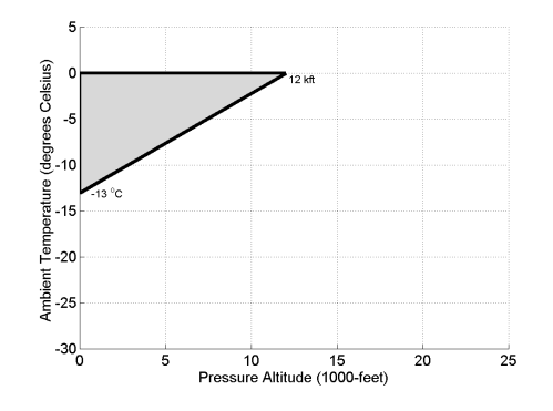
Appendix O icing conditions are defined by the parameters of altitude, vertical and horizontal extent, temperature, liquid water content, and water mass distribution as a function of drop diameter distribution.
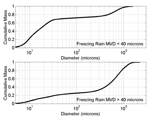
(a) Freezing Drizzle (Conditions with spectra maximum drop diameters from 100 μm to 500 μm):
(1) Pressure altitude range: 0 to 6 706 m (22 000 feet) MSL.
(2) Maximum vertical extent: 3 656 m (12 000 feet).
(3) Horizontal extent: standard distance of 32.2 km (17.4 nautical miles).
(4) Total liquid water content:
Note: Liquid water content (LWC) in grams per cubic meter (g/m3) based on horizontal extent standard distance of 32.2 km (17.4 nautical miles).
Figure 1 – Appendix O, Freezing Drizzle, Liquid Water Content
(5) Drop diameter distribution:
Figure 2 – Appendix O, Freezing Drizzle, Drop Diameter Distribution
(6) Altitude and temperature envelope:
Figure 3 – Appendix O, Freezing Drizzle, Altitude and Temperature
(b) Freezing Rain (Conditions with spectra maximum drop diameters greater than 500 μm):
(1) Pressure altitude range: 0 to 3656 m (12000 ft) MSL.
(2) Maximum vertical extent: 2134 m (7000 ft).
(3) Horizontal extent: standard distance of 32.2 km (17.4 nautical miles).
(4) Total liquid water content:
Note: LWC in grams per cubic meter (g/m3) based on horizontal extent standard distance of 32.2 km (17.4 nautical miles).
Figure 4 – Appendix O, Freezing Rain, Liquid Water Content
(5) Drop diameter distribution:
Figure 5 – Appendix O, Freezing Rain, Drop Diameter Distribution
(6) Altitude and temperature envelope:
Figure 6 – Appendix O, Freezing Rain, Altitude and Temperature
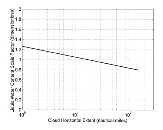
(c) Horizontal extent
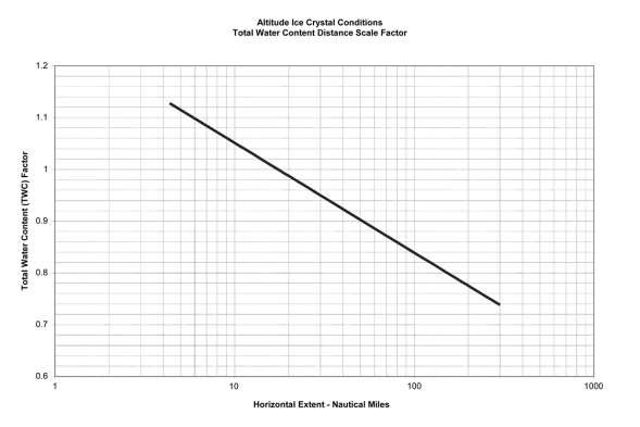
The liquid water content for freezing drizzle and freezing rain conditions for horizontal extents other than the standard 32.2 km (17.4 nautical miles) can be determined by the value of the liquid water content determined from Figure 1 or Figure 4, multiplied by the factor provided in Figure 7, which is defined by the following equation:
S = 1.266 – 0.213 log10(H)
Where S = Liquid Water Content Scale Factor (dimensionless) and H = horizontal extent in nautical miles
Figure 7 – Appendix O, Horizontal Extent, Freezing Drizzle and Freezing Rain
[Amdt 25/16]
Part II – Airframe ice accretions
ED Decision 2015/008/R
(a) General.
The most critical ice accretion in terms of aeroplane performance and handling qualities for each flight phase must be used to show compliance with the applicable aeroplane performance and handling qualities requirements for icing conditions contained in Subpart B. Applicants must demonstrate that the full range of atmospheric icing conditions specified in part I of this appendix have been considered, including drop diameter distributions, liquid water content, and temperature appropriate to the flight conditions (for example, configuration, speed, angle-of-attack, and altitude).
(1) For an aeroplane certified in accordance with CS 25.1420(a)(1), the ice accretions for each flight phase are defined in part II, paragraph (b) of this appendix.
(2) For an aeroplane certified in accordance with CS 25.1420(a)(2), the most critical ice accretion for each flight phase defined in part II, paragraphs (b) and (c) of this appendix, must be used. For the ice accretions defined in part II, paragraph (c) of this appendix, only the portion of part I of this appendix in which the aeroplane is capable of operating safely must be considered.
(3) For an aeroplane certified in accordance with CS 25.1420(a)(3), the ice accretions for each flight phase are defined in part II, paragraph (c) of this appendix.
(b) Ice accretions for aeroplanes certified in accordance with CS 25.1420(a)(1) or (a)(2).
(1) En-route ice is the en-route ice as defined by part II, paragraph (c)(3), of this appendix, for an aeroplane certified in accordance with CS 25.1420(a)(2), or defined by part II, paragraph (a)(3), of Appendix C, for an aeroplane certified in accordance with CS 25.1420(a)(1), plus:
(i) Pre-detection ice as defined by part II paragraph (b)(5) of this appendix; and
(ii) The ice accumulated during the transit of one cloud with a horizontal extent of 32.2 km (17.4 nautical miles) in the most critical of the icing conditions defined in part I of this appendix and one cloud with a horizontal extent of 32.2 km (17.4 nautical miles) in the continuous maximum icing conditions defined in Appendix C.
(2) Holding ice is the holding ice defined by part II, paragraph (c)(4), of this appendix, for an aeroplane certified in accordance with CS 25.1420(a)(2), or defined by part II, paragraph (a)(4) of Appendix C, for an aeroplane certified in accordance with CS 25.1420(a)(1), plus:
(i) Pre-detection ice as defined by part II, paragraph (b)(5) of this appendix; and
(ii) The ice accumulated during the transit of one cloud with a 32.2 km (17.4 nautical miles) horizontal extent in the most critical of the icing conditions defined in part I of this appendix and one cloud with a horizontal extent of 32.2 km (17.4 nautical miles) in the continuous maximum icing conditions defined in Appendix C.
(iii) Except the total exposure to holding ice conditions does not need to exceed 45 minutes
(3) Approach ice is the more critical of the holding ice defined by part II, paragraph (b)(2) of this appendix, or the ice calculated in the applicable paragraph (b)(3)(i) or (ii) of part II of this appendix:
(i) For an aeroplane certified in accordance with CS 25.1420(a)(2), the ice accumulated during descent from the maximum vertical extent of the icing conditions defined in part I of this appendix to 610 m (2 000 feet) above the landing surface in the cruise configuration, plus transition to the approach configuration, plus:
(A) Pre-detection ice, as defined by part II, paragraph (b)(5) of this appendix; and
(B) The ice accumulated during the transit at 610 m (2 000 feet) above the landing surface of one cloud with a horizontal extent of 32.2 km (17.4 nautical miles) in the most critical of the icing conditions defined in part I of this appendix and one cloud with a horizontal extent of 32.2 km (17.4 nautical miles) in the continuous maximum icing conditions defined in Appendix C.
(ii) For an aeroplane certified in accordance with CS 25.1420(a)(1), the ice accumulated during descent from the maximum vertical extent of the maximum continuous icing conditions defined in part I of Appendix C to 610 m (2 000 feet) above the landing surface in the cruise configuration, plus transition to the approach configuration, plus:
(A) Pre-detection ice, as defined by part II, paragraph (b)(5) of this appendix; and
(B) The ice accumulated during the transit at 610 m (2 000 feet) above the landing surface of one cloud with a horizontal extent of 32.2 km (17.4 nautical miles) in the most critical of the icing conditions defined in part I of this appendix and one cloud with a horizontal extent of 32.2 km (17.4 nautical miles) in the continuous maximum icing conditions defined in Appendix C.
(4) Landing ice is the more critical of the holding ice as defined by part II, paragraph (b)(2) of this appendix, or the ice calculated in the applicable paragraph (b)(4)(i) or (ii) of part II of this appendix:
(i) For an aeroplane certified in accordance with CS 25.1420(a)(2), the ice accretion defined by part II, paragraph (c)(5)(i) of this appendix, plus a descent from 610 m (2 000 feet) above the landing surface to a height of 61 m (200 feet) above the landing surface with a transition to the landing configuration in the icing conditions defined in part I of this appendix, plus:
(A) Pre-detection ice, as defined in part II, paragraph (b)(5) of this appendix; and
(B) The ice accumulated during an exit manoeuvre, beginning with the minimum climb gradient required by CS 25.119, from a height of 61 m (200 feet) above the landing surface through one cloud with a horizontal extent of 32.2 km (17.4 nautical miles) in the most critical of the icing conditions defined in part I of this appendix and one cloud with a horizontal extent of 32.2 km (17.4 nautical miles) in the continuous maximum icing conditions defined in Appendix C.
(ii) For an aeroplane certified in accordance with CS 25.1420(a)(1), the ice accumulated in the maximum continuous icing conditions defined in Appendix C, during a descent from the maximum vertical extent of the icing conditions defined in Appendix C, to 610 m (2 000 feet) above the landing surface in the cruise configuration, plus transition to the approach configuration and flying for 15 minutes at 610 m (2 000 feet) above the landing surface, plus a descent from 610 m (2 000 feet) above the landing surface to a height of 61 m (200 feet) above the landing surface with a transition to the landing configuration, plus:
(A) Pre-detection ice, as described by part II, paragraph (b)(5) of this appendix; and
(B) The ice accumulated during an exit manoeuvre, beginning with the minimum climb gradient required by CS 25.119, from a height of 61 m (200 feet) above the landing surface through one cloud with a horizontal extent of 32.2 km (17.4 nautical miles) in the most critical of the icing conditions defined in part I of this appendix and one cloud with a horizontal extent of 32.2 km (17.4 nautical miles) in the continuous maximum icing conditions defined in Appendix C.
(5) Pre-detection ice is the ice accretion before detection of Appendix O conditions that require exiting per CS 25.1420(a)(1) and (a)(2). It is the pre-existing ice accretion that may exist from operating in icing conditions in which the aeroplane is approved to operate prior to encountering the icing conditions requiring an exit, plus the ice accumulated during the time needed to detect the icing conditions, followed by two minutes of further ice accumulation to take into account the time for the flight crew to take action to exit the icing conditions, including coordination with air traffic control.
(i) For an aeroplane certified in accordance with CS 25.1420(a)(1), the pre-existing ice accretion must be based on the icing conditions defined in Appendix C.
(ii) For an aeroplane certified in accordance with CS 25.1420(a)(2), the pre-existing ice accretion must be based on the more critical of the icing conditions defined in Appendix C, or the icing conditions defined in part I of this appendix in which the aeroplane is capable of safely operating.
(c) Ice accretions for aeroplanes certified in accordance with CS 25.1420(a)(2) or CS 25.1420(a)(3).
For an aeroplane certified in accordance with CS 25.1420(a)(2), only the portion of the icing conditions of part I of this appendix in which the aeroplane is capable of operating safely must be considered.
(1) Take-off ice is the most critical ice accretion on unprotected surfaces, and any ice accretion on the protected surfaces appropriate to normal ice protection system operation, occurring between the end of the take-off distance and 122 m (400 feet) above the take-off surface, assuming accretion starts at the end of the take-off distance in the take-off maximum icing conditions defined in part I of this appendix.
(2) Final take-off ice is the most critical ice accretion on unprotected surfaces, and any ice accretion on the protected surfaces appropriate to normal ice protection system operation, between 122 m (400 feet) and either 457 m (1 500 feet) above the take-off surface, or the height at which the transition from the take-off to the en-route configuration is completed and VFTO is reached, whichever is higher. Ice accretion is assumed to start at lift-off the end of the take-off distance in the icing conditions defined in part I of this appendix.
(3) En-route ice is the most critical ice accretion on the unprotected surfaces, and any ice accretion on the protected surfaces appropriate to normal ice protection system operation, during the en-route flight phase in the icing conditions defined in part I of this appendix.
(4) Holding ice is the most critical ice accretion on the unprotected surfaces, and any ice accretion on the protected surfaces appropriate to normal ice protection system operation, resulting from 45 minutes of flight within a cloud with a 32.2 km (17.4 nautical miles) horizontal extent in the icing conditions defined in part I of this appendix, during the holding phase of flight.
(5) Approach ice is the ice accretion on the unprotected surfaces, and any ice accretion on the protected surfaces appropriate to normal ice protection system operation, resulting from the more critical of the:
(i) Ice accumulated in the icing conditions defined in part I of this appendix during a descent from the maximum vertical extent of the icing conditions defined in part I of this appendix, to 610 m (2 000 feet) above the landing surface in the cruise configuration, plus transition to the approach configuration and flying for 15 minutes at 610 m (2 000 feet) above the landing surface; or
(ii) Holding ice as defined by part II, paragraph (c)(4) of this appendix.
(6) Landing ice is the ice accretion on the unprotected surfaces, and any ice accretion on the protected surfaces appropriate to normal ice protection system operation, resulting from the more critical of the:
(i) Ice accretion defined by part II, paragraph (c)(5)(i), of this appendix, plus ice accumulated in the icing conditions defined in part I of this appendix during a descent from 610 m (2 000 feet) above the landing surface to a height of 61 m (200 feet) above the landing surface with a transition to the landing configuration, followed by a go-around at the minimum climb gradient required by CS 25.119, from a height of 61 m (200 feet) above the landing surface to 610 m (2 000 feet) above the landing surface, flying for 15 minutes at 610 m (2 000 feet) above the landing surface in the approach configuration, and a descent to the landing surface (touchdown) in the landing configuration; or
(ii) Holding ice as defined by part II paragraph (c)(4) of this appendix.
(7) For both unprotected and protected parts, the ice accretion for the take-off phase must be determined for the icing conditions defined in part I of this appendix, using the following assumptions:
(i) The aerofoils, control surfaces, and, if applicable, propellers are free from frost, snow, or ice at the start of take-off;
(ii) The ice accretion begins at lift-off;
(iii) The critical ratio of thrust/power-to-weight;
(iv) Failure of the critical engine occurs at VEF; and
(v) Crew activation of the ice protection system is in accordance with a normal operating procedure provided in the Aeroplane Flight Manual, except that after beginning the take-off roll, it must be assumed that the crew takes no action to activate the ice protection system until the aeroplane is at least 122 m (400 feet) above the take-off surface.
(d) The ice accretion before the ice protection system has been activated and is performing its intended function is the critical ice accretion formed on the unprotected and normally protected surfaces before activation and effective operation of the ice protection system in the icing conditions defined in part I of this appendix. This ice accretion only applies in showing compliance to CS 25.143(j) and 25.207(h).
(e) In order to reduce the number of ice accretions to be considered when demonstrating compliance with the requirements of CS 25.21(g), any of the ice accretions defined in this appendix may be used for any other flight phase if it is shown to be at least as critical as the specific ice accretion defined for that flight phase. Configuration differences and their effects on ice accretions must be taken into account.
(f) The ice accretion that has the most adverse effect on handling qualities may be used for aeroplane performance tests provided any difference in performance is conservatively taken into account.
[Amdt 25/16]
Appendix P – Mixed phase and ice crystal icing envelope (Deep convective clouds)
ED Decision 2015/008/R
The ice crystal icing envelope is depicted in Figure 1 below.
Figure 1 – Convective Cloud Ice Crystal Envelope
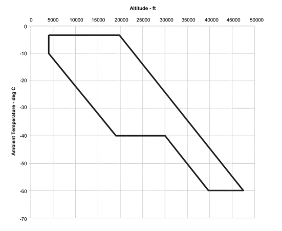
Within the envelope, total water content (TWC) in g/m3 has been determined based upon the adiabatic lapse defined by the convective rise of 90 % relative humidity air from sea level to higher altitudes and scaled by a factor of 0.65 to a standard cloud length of 32.2 km (17.4 nautical miles). Figure 2 displays TWC for this distance over a range of ambient temperature within the boundaries of the ice crystal envelope specified in Figure 1.
Figure 2 – Total Water Content
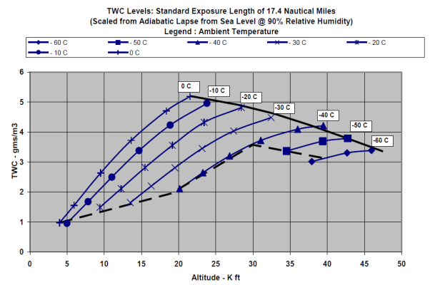
Ice crystal size median mass dimension (MMD) range is 50–200 microns (equivalent spherical size) based upon measurements near convective storm cores. The TWC can be treated as completely glaciated (ice crystal) except as noted in the Table 1.
Table 1 – Supercooled Liquid Portion of TWC
|
Temperature range – deg C |
Horizontal cloud length |
LWC – g/m3 |
|
0 to -20 |
≤92.6 km (50 nautical miles) |
≤1.0 |
|
0 to -20 |
Indefinite |
≤0.5 |
|
< -20 |
|
0 |
The TWC levels displayed in Figure 2 represent TWC values for a standard exposure distance (horizontal cloud length) of 32.2 km (17.4 nautical miles) that must be adjusted with length of icing exposure.
Figure 3 – Exposure Length Influence on TWC
[Amdt 25/16]
Appendix Q – Additional airworthiness requirements for approval of a Steep Approach Landing (SAL) capability
ED Decision 2016/010/R
(See AMC to Appendix Q)
ED Decision 2013/010/R
This Appendix contains airworthiness requirements that enable an aeroplane to obtain approval for a steep approach landing capability using an approach path angle greater than or equal to 4.5° (a gradient of 7.9 %).
The requirements of this Appendix cover only CS-25 Subparts B and G and they apply in lieu of CS 25.121(d). They also apply in lieu of CS 25.125 if a reduced landing distance is sought, or if the landing procedure (speed, configuration, etc.) differs significantly from normal operation, or if the screen height is greater than 50 ft. Additional requirements may apply with respect to aeroplane systems or equipment or other relevant items such as autopilot, flight guidance, or GPWS. It is likely that the GPWS mode 1 (sink rate) envelope will need modification to prevent nuisance alerts. Also, the structural implications of the increased probability of high rates of descent at touchdown must be considered.
If a steep approach approval is required for flight in icing conditions, substantiation must be provided accordingly for the steep approach condition.
An applicant may choose to schedule information for an all-engines approach or for an approach with one engine inoperative. If an all-engines approach is scheduled, it is assumed that a diversion is required if an engine failure occurs prior to the decision to land.
[Amdt 25/13]
ED Decision 2013/010/R
For the purposes of this Appendix:
— Steep Approach Landing: An approach to land made using a glide path angle greater than or equal to 4.5°, as selected by the applicant.
— Screen Height: The reference height above the runway surface from which the landing distance is measured. The screen height is a height selected by the applicant, at 50 ft or another value from 35 to 60 ft.
— VREF(SAL) is the calibrated airspeed selected by the applicant used during the stabilised approach at the selected approach path angle and maintained down to the screen height defined above. VREF(SAL) may not be less than 1.23 VSR, VMCL, or a speed that provides the manoeuvring capability specified in CS 25.143(h), whichever is greater and may be different from the VREF used for standard approaches.
— VREF(SAL)-1 is the calibrated airspeed selected by the applicant used during the stabilised one-engine-inoperative approach at the selected approach path angle and maintained down to the screen height defined above. VREF(SAL)-1 may not be less than VREF(SAL).
[Amdt 25/13]
(SAL) 25.3 Steep Approach Landing Distance
ED Decision 2013/010/R
(Applicable only if a reduced landing distance is sought, or if the landing procedure (speed, configuration, etc.) differs significantly from normal operation, or if the screen height is greater than 50 ft.)
(a) The steep approach landing distance is the horizontal distance necessary to land and to come to a complete stop from the landing screen height and must be determined (for standard temperatures, at each weight, altitude and wind within the operational limits established by the applicant for the aeroplane) as follows:
(1) The aeroplane must be in the all-engines-operating or one-engine-inoperative steep approach landing configuration, as applicable.
(2) A stabilised approach, with a calibrated airspeed of VREF(SAL) or VREF(SAL)-1 as appropriate, and at the selected approach angle must be maintained down to the screen height.
(3) Changes in configuration, power or thrust, and speed must be made in accordance with the established procedures for service operation (see AMC 25.125(b)(3)).
(4) The landing must be made without excessive vertical acceleration, tendency to bounce, nose over or ground loop and with a vertical touchdown velocity not greater than 6 ft/sec.
(5) The landings may not require exceptional piloting skill or alertness.
(b) The landing distance must be determined on a level, smooth, dry, hard-surfaced runway (see AMC 25.125(c)). In addition,
(1) The pressures on the wheel braking systems may not exceed those specified by the brake manufacturer;
(2) The brakes may not be used so as to cause excessive wear of brakes or tyres (see AMC 25.125(c)(2)); and
(3) Means other than wheel brakes may be used if that means
(i) Is safe and reliable;
(ii) Is used so that consistent results can be expected in service; and
(iii) Is such that exceptional skill is not required to control the aeroplane.
(c) Reserved.
(d) Reserved.
(e) The landing distance data must include correction factors for not more than 50 % of the nominal wind components along the landing path opposite to the direction of landing, and not less than 150 % of the nominal wind components along the landing path in the direction of landing.
(f) If any device is used that depends on the operation of any engine, and if the landing distance would be noticeably increased when a landing is made with that engine assumed to fail during the final stages of an all-engines-operating steep approach, the steep approach landing distance must be determined with that engine inoperative unless the use of compensating means will result in a landing distance not more than that with each engine operating.
[Amdt 25/13]
(SAL) 25.4 Climb: One-engine-inoperative
ED Decision 2013/010/R
In a configuration corresponding to the normal all-engines-operating procedure in which VSR for this configuration does not exceed 110 % of the VSR for the related all-engines-operating steep approach landing configuration, the steady gradient of climb may not be less than 2.1 % for two-engined aeroplanes, 2.4 % for three-engined aeroplanes, and 2.7 % for four-engined aeroplanes, with:
(a) The critical engine inoperative, the remaining engines at the go-around power or thrust setting;
(b) The maximum landing weight;
(c) A climb speed of VREF(SAL); and
(d) The landing gear retracted.
[Amdt 25/13]
(SAL) 25.5 Safe operational and flight characteristics
ED Decision 2018/005/R
(a) It must be demonstrated that it is possible to complete a stabilised approach in calm air down to the commencement of the landing flare, followed by a touchdown and landing without displaying any hazardous characteristics for the following conditions (see AMC to Appendix Q, (SAL) 25.5):
(1) The selected approach path angle at VREF(SAL) or VREF(SAL)-1 as appropriate;
(2) An approach path angle 2° steeper than the selected approach path angle, at VREF(SAL) or VREF(SAL)-1 as appropriate; and
(3) The selected approach path angle at VREF(SAL) minus 5 knots or VREF(SAL)-1 minus 5 knots as appropriate.
(b) For conditions (a)(1), (a)(2), and (a)(3):
(1) The demonstration must be conducted at the most critical weight and centre of gravity, either with all-engines-operating or with the critical engine inoperative, as appropriate;
(2) The rate of descent must be reduced to 3 feet per second or less before touchdown;
(3) Below a height of 200 ft no action shall be taken to increase power or thrust apart from those small changes which are necessary to maintain an accurate approach;
(4) No nose depression by use of longitudinal control shall be made after initiating the flare other than those small changes necessary to maintain a continuous and consistent flare flight path; and
(5) The flare, touchdown and landing may not require exceptional piloting skill or alertness.
(c) For conditions (a)(1) and (a)(3), the flare must not be initiated above the screen height.
(d) For condition (a)(2), it must be possible to achieve an approach path angle 2° steeper than the selected approach path angle in all configurations which exist down to the initiation of the flare, which must not occur above 150 % of the screen height. The flare technique used must be substantially unchanged from that recommended for use at the selected approach path angle.
(e) All-engines-operating steep approach.
It must be demonstrated that the aeroplane can safely transition from the all-engines-operating steep landing approach to:
(1) the all-engines-operating go-around as per standard procedure; and
(2) the one-engine- inoperative approach climb configuration with one engine having been made inoperative, for the following conditions:
(i) The selected steep approach angle;
(ii) An approach speed of VREF(SAL);
(iii) The most critical weight and centre of gravity; and
(iv) For propeller-powered aeroplanes, the propeller of the inoperative engine shall be at the position it automatically assumes following an engine failure at high power.
(f) In addition, for propeller-powered aeroplanes, it must be demonstrated that controllability is maintained following an engine failure at approach power and with the propeller at the position it automatically assumes.
(g) The height loss during the manoeuvre required by subparagraph (SAL) 25.5(e) must be determined.
(h) It must be demonstrated that the aeroplane is safely controllable during a landing with one engine having been made inoperative during the final stages of an all-engines-operating steep approach for the following conditions:
(1) The selected steep approach angle;
(2) An approach speed of VREF(SAL);
(3) The most critical weight and centre of gravity; and
(4) For propeller-powered aeroplanes, the propeller of the inoperative engine shall be at the position it automatically assumes following an engine failure at approach power.
(i) One-engine-inoperative steep approach.
It must be demonstrated that the aeroplane can safely transition from the one-engine-inoperative steep landing approach to the approach climb configuration for the following conditions:
(1) The selected steep approach angle;
(2) An approach speed of VREF(SAL)-1;
(3) The most critical weight and centre of gravity; and
(4) For propeller-powered aeroplanes, the propeller of the inoperative engine may be feathered.
[Amdt 25/13]
[Amdt 25/21]
AMC to Appendix Q, (SAL) 25.5 Safe operational and flight characteristics
ED Decision 2016/010/R
(a) For the approach demonstrations required by (SAL) 25.5(a), due account should be taken of:
(1) The systems’ aspects of the power/thrust levers being at idle (e.g. arming of ground lift dump);
(2) The most adverse flight idle power/thrust (e.g. effects of engine bleeds or FADEC idle power/thrust control); and
(3) The effects on controllability from the use of auxiliary drag devices such as flight spoilers (e.g. increased stall warning and stall speeds, loss of manoeuvrability).
(b) For the flare, touchdown and landing demonstrations required by (SAL) 25.5(a), there should not be any occurrence of:
(1) Stall warning;
(2) Tail strike; or
(3) Any other characteristic that would interfere with the completion of the landing (e.g. automatic thrust increase).
(c) For the go-around demonstrations required by (SAL) 25.5(e) and (i), due account should be taken of time delays associated with automatic or manual retraction of auxiliary drag devices.
[Amdt No: 25/13]
[Amdt No: 25/18]
(SAL) 25.6 Aeroplane Flight Manual
ED Decision 2013/010/R
For steep approach landing, the AFM shall include the following:
(a) The steep approach landing distance determined in accordance with paragraph (SAL) 25.3 of this Appendix for the selected screen height and aeroplane configuration. The landing distance data may additionally include correction factors for runway slope and temperature other than standard, within the operational limits of the aeroplane, and may provide the required landing field length including the appropriate factors for operational variations prescribed in the relevant operating regulation.
(b) The more limiting of the landing weight, altitude and temperature (WAT) limits derived in accordance with:
(1) CS 25.119, and
(2) The one-engine-inoperative approach climb requirement of paragraph (SAL) 25.4 of this Appendix.
(c) Appropriate limitations and detailed normal, non-normal, and emergency procedures. Where an aeroplane is not approved for deliberate one-engine-inoperative steep approach landings, this limitation shall be stated.
(d) A statement that the presentation of the steep approach limitations, procedures, and performance reflects the capability of the aeroplane to perform steep approach landings but that it does not constitute operational approval.
(e) A statement of headwind and crosswind limitations if they are different from those for non-steep approaches. The tailwind limitation is 5 knots unless test evidence shows that more than 5 knots is acceptable.
(f) The reference steep approach glide slope angle and the screen height used for determination of the landing distance.
(g) The height loss during a go-around from the all-engines-operating steep landing approach to the approach climb configuration with one engine made inoperative, determined in accordance with (SAL) 25.5(g).
[Amdt No: 25/13]
Appendix R – HIRF Environments and Equipment HIRF Test Levels
ED Decision 2015/019/R
This Appendix specifies the HIRF environments and equipment HIRF test levels for electrical and electronic systems under CS 25.1317. The field strength values for the HIRF environments and equipment HIRF test levels are expressed in root-mean-square units measured during the peak of the modulation cycle.
(a) HIRF environment I is specified in the following table:
Table 1 — HIRF environment I
|
FREQUENCY |
FIELD STRENGTH (V/m) |
|
|
PEAK |
AVERAGE |
|
|
10 kHz – 2 MHz |
50 |
50 |
|
2 MHz – 30 MHz |
100 |
100 |
|
30 MHz – 100 MHz |
50 |
50 |
|
100 MHz – 400 MHz |
100 |
100 |
|
400 MHz – 700 MHz |
700 |
50 |
|
700 MHz – 1 GHz |
700 |
100 |
|
1 GHz – 2 GHz |
2 000 |
200 |
|
2 GHz – 6 GHz |
3 000 |
200 |
|
6 GHz – 8 GHz |
1 000 |
200 |
|
8 GHz – 12 GHz |
3 000 |
300 |
|
12 GHz – 18 GHz |
2 000 |
200 |
|
18 GHz – 40 GHz |
600 |
200 |
In this table, the higher field strength applies to the frequency band edges.
(b) HIRF environment II is specified in the following table:
Table 2 — HIRF environment II
|
FREQUENCY |
FIELD STRENGTH (V/m) |
|
|
PEAK |
AVERAGE |
|
|
10 kHz – 500 kHz |
20 |
20 |
|
500 kHz – 2 MHz |
30 |
30 |
|
2 MHz – 30 MHz |
100 |
100 |
|
30 MHz – 100 MHz |
10 |
10 |
|
100 MHz – 200 MHz |
30 |
10 |
|
200 MHz – 400 MHz |
10 |
10 |
|
400 MHz – 1 GHz |
700 |
40 |
|
1 GHz – 2 GHz |
1 300 |
160 |
|
2 GHz – 4 GHz |
3 000 |
120 |
|
4 GHz – 6 GHz |
3 000 |
160 |
|
6 GHz – 8 GHz |
400 |
170 |
|
8 GHz – 12 GHz |
1 230 |
230 |
|
12 GHz – 18 GHz |
730 |
190 |
|
18 GHz – 40 GHz |
600 |
150 |
In this table, the higher field strength applies to the frequency band edges.
(c) Equipment HIRF test level 1.
(1) From 10 kilohertz (kHz) to 400 megahertz (MHz), use conducted susceptibility tests with Continuous Wave (CW) and 1 kHz square wave modulation with 90 % depth or greater. The conducted susceptibility current must start at a minimum of 0.6 milliamperes (mA) at 10 kHz, increasing 20 decibels (dB) per frequency decade to a minimum of 30 mA at 500 kHz.
(2) From 500 kHz to 40 MHz, the conducted susceptibility current must be at least 30 mA.
(3) From 40 MHz to 400 MHz, use conducted susceptibility tests, starting at a minimum of 30 mA at 40 MHz, decreasing 20 dB per frequency decade to a minimum of 3 mA at 400 MHz.
(4) From 100 MHz to 400 MHz, use radiated susceptibility tests at a minimum of 20 volts per meter (V/m) peak with CW and 1 kHz square wave modulation with 90 % depth or greater.
(5) From 400 MHz to 8 gigahertz (GHz), use radiated susceptibility tests at a minimum of 150 V/m peak with pulse modulation of 4 % duty cycle with a 1 kHz pulse repetition frequency. This signal must be switched on and off at a rate of 1 Hz with a duty cycle of 50 %.
(d) Equipment HIRF test level 2. Equipment HIRF test level 2 is HIRF environment II in Table II of this Appendix reduced by acceptable aircraft transfer function and attenuation curves. Testing must cover the frequency band of 10 kHz to 8 GHz.
(e) Equipment HIRF test level 3.
(1) From 10 kHz to 400 MHz, use conducted susceptibility tests, starting at a minimum of 0.15 mA at 10 kHz, increasing 20 dB per frequency decade to a minimum of 7.5 mA at 500 kHz.
(2) From 500 kHz to 40 MHz, use conducted susceptibility tests at a minimum of 7.5 mA.
(3) From 40 to 400 MHz, use conducted susceptibility tests, starting at a minimum of 7.5 mA at 40 MHz, decreasing 20 dB per frequency decade to a minimum of 0.75 mA at 400 MHz.
(4) From 100 MHz to 8 GHz, use radiated susceptibility tests at a minimum of 5 V/m.
[Amdt 25/17]
Appendix S – Airworthiness requirements for non-commercially operated aeroplanes and low-occupancy aeroplanes
ED Decision 2017/015/R
(See AMC to Appendix S)
ED Decision 2017/015/R
(a) Applicability: unless otherwise specified within, the requirements of this Appendix are applicable to the passenger or crew compartments (interiors) of:
(1) non-commercially operated aeroplanes with a passenger seating configuration of:
(i) up to and including 19 passengers; or
(ii) up to and including one half of the maximum passenger seating capacity of the type-certified aeroplane as indicated in the aeroplane type certificate data sheet (TCDS), provided that:
(A) the total number of passengers approved for occupancy during taxiing, take-off or landing does not exceed 150 per deck; and
(B) the total number of passengers approved for occupancy during taxiing, take-off or landing on a deck does also not exceed one half of the maximum passenger seating capacity for that deck as indicated in the aeroplane TCDS.
(2) low-occupancy aeroplanes irrespective of the type of operations (commercial or non-commercial). A low-occupancy aeroplane is defined as an aeroplane which has a passenger seating configuration of:
(i) up to and including 19; or
(ii) up to and including one third of the maximum passenger seating capacity of the type-certified aeroplane as indicated in the aeroplane TCDS, provided that:
(A) the total number of passenger seats approved for occupancy during taxiing, take-off, or landing does not exceed 100 per deck; and
(B) the total number of passenger seats approved for occupancy during taxiing, take-off, or landing in any individual zone between pairs of emergency exits (or any dead end zone) does also not exceed one-third of the sum of the passenger seat allowances for the emergency exit pairs bounding that zone, using the passenger seat allowance for each emergency exit pair as defined by the applicable certification basis of the aeroplane. For the purpose of determining compliance with this zonal limitation, in the case of an aeroplane which has deactivated emergency exits, it shall be assumed that all emergency exits are functional.
(b) Aeroplane Flight Manual (AFM) Limitation: if compliance with any part of this Appendix limits the aeroplane to non-commercial operations, this limitation must be included in the ‘Limitations’ Section of the AFM.
[Amdt 25/19]
AMC to Appendix S, S25.1 Passenger seating configuration
ED Decision 2017/015/R
Where this term is used in Appendix S:
‘Passenger seating configuration’ means the passenger seating capacity established during the certification process (either type certificate (TC), supplemental type certificate (STC) or change to the TC or STC, as relevant), conducted for the particular cabin interior and emergency exit arrangement of the aeroplane considered.
The passenger seating configuration is equal to, or less than, the maximum passenger seating capacity of the relevant type-certified aeroplane as indicated in the aeroplane type certificate data sheet (TCDS).
The passenger seating configuration may be less than the total number of passenger seats in the aeroplane that are approved for occupancy during taxiing, take-off, and landing, if seats in excess are installed; in such a case the requirement S25.40(c) Seats in Excess must be complied with.
[Amdt 25/19]
S25.10 General Cabin Arrangement
ED Decision 2017/015/R
(a) Interior Doors on Non-Commercially Operated Aeroplanes (See AMC to Appendix S, S25.10(a)): For a non-commercially operated aeroplane, installation of doors that results in non-compliance with CS 25.813(e) is acceptable provided that it is ensured by design and procedure that:
(1) each door is open before entering any of the taxiing, take-off, and landing phases;
(2) each door remains open during taxiing, take-off, and landing, and especially during and after a crash landing; and
(3) in the case of any probable failure or jamming of a door in a position other than fully open, any occupant is able, from any compartment separated by that door, to restore in an easy and simple manner a sufficient opening to access the compartment on the other side of the door.
(b) Interior Doors on Commercially Operated Aeroplanes (See AMC to Appendix S, S25.10(b)): For a low-occupancy aeroplane having a passenger seating configuration of 19 or less, installation of doors that results in non-compliance with CS 25.813(e) is acceptable provided that the conditions of S25.10(a)(1), S25.10(a)(2) and S25.10(a)(3) are complied with and the following additional requirements are met for each passenger compartment created by a door or doors:
(1) Within the compartment, there is at least one emergency exit above the waterline on each side of the fuselage that meets at least the requirements of a type IV emergency exit for a compartment that has a passenger seating configuration of nine seats or less, or of a type III emergency exit otherwise; or
(2) Within the compartment, there is at least one emergency exit above the waterline on one side of the fuselage that meets at least the requirements of a type IV emergency exit for a compartment that has a passenger seating configuration of nine seats or less, or of a type III emergency exit otherwise, and:
(i) an occupant of the compartment would not need to go through more than one door to access an emergency exit above the waterline on the other side of the fuselage; and
(ii) the demonstration of compliance with the provisions S25.10(a)(1) and (2) does not rely on any passenger action, nor involve any flight crew member leaving their position in the cockpit.
(c) Isolated Compartments: each cabin compartment isolated from the rest of the cabin such that a fire starting in the compartment would not be directly and quickly detected by the occupants of another compartment, in an aeroplane that has a passenger seating configuration of 20 or more, or which has a cabin length of more than 18.29 m (60 ft), must be equipped with a smoke/fire detection system or equivalent which allows detection within one minute after the start of a fire and provides a visual indication in the cockpit, or a visual indication or audible warning in the passenger cabin that would be readily detected by a cabin crew member. However, if it can be demonstrated that a fire would be directly and quickly detected because the compartment is likely to be occupied for the majority of the flight time, such a system is not required (See AMC to Appendix S, S25.10(c)).
(d) Deactivation of existing Emergency Exits: Deactivation of one of more emergency exits that results in non-compliance with CS 25.807(e) is acceptable, provided that compliance with the following requirements is shown (See AMC to Appendix S, S25.10(d) and (e)):
(1) the number of passenger seats allowed in a zone between two remaining adjacent pairs of emergency exits is limited to one half of the combined rated capacity of the two pairs of emergency exits (rounded to the nearest whole number);
(2) the number of passenger seats allowed in a zone with only one remaining pair of emergency exits at one end (a so called dead end zone) is limited to one half of the rated capacity of the pair of emergency exits (rounded to the nearest whole number); and
(3) the distance from each passenger seat to at least one remaining emergency exit, on each side of the fuselage, remains compatible with easy egress from the aeroplane.
(e) Distance between Emergency Exits: deactivation of emergency exits which results in non-compliance with CS 25.807(f)(4) is acceptable on non-commercially operated aeroplanes only, provided that:
(1) compliance with S25.10(d) is shown; and
(2) a distance of more than 18.29 m (60 ft) between adjacent remaining emergency exits is created only once per side of the fuselage on each deck (See AMC to Appendix S, S25.10(d) and (e)).
[Amdt 25/19]
AMC to Appendix S, S25.10(a) Interior Doors on Non-Commercially Operated Aeroplanes
ED Decision 2017/015/R
(1) The following provides acceptable means to ensure that a door is open before entering any of the taxiing, take-off, and landing phase, as required by S25.10(a)(1):
(a) The door should be conspicuously placarded on both sides to be in the safe (i.e. open and secured) position during taxiing, take-off, and landing;
(b) The operation of the door and the requirement that the door be secured open for taxiing, take-off, and landing must be the subject of a passenger briefing, and the requirement for this briefing must be part of the AFM; for the purpose of this briefing, a description of the operation of the internal door should be made available to the flight crew; and
(c) There should be a means to signal to the flight crew in a timely manner if the door is not open and secured in a safe position before entering any of the taxiing, take-off, or landing phases. The indication should be triggered during the descent phase, early enough to enable the flight crew to take appropriate action before entering the approach phase, unless the aeroplane is required to have at least one cabin crew member on board. Appropriate procedures for crew action should be established.
(2) The following provides acceptable means to ensure that the door remains open during taxiing, take-off, and landing, and especially during and after a crash landing, as required by S25.10(a)(2):
(a) Dual means should be provided to secure the door in the open position for taxiing, take-off, and landing. Each of those dual means should be capable of reacting to the inertia loads specified in CS 25.561; and
(b) The indication to the flight crew mentioned in the above condition (1)(c) should be triggered without delay and remain active whenever the door is not in the safe position during any of the taxiing, take-off, and landing flight phases. Appropriate procedures for crew action should be established.
(3) Regarding the indication mentioned in the above paragraphs (1)(c) and (2)(b), if several interior doors are installed, it might not be necessary to provide a distinct indication for each door on the flight deck. Door position indication in the cockpit may be achieved by means of a single visual indication serving all interior doors installed in the aeroplane, provided that at least one of the following two conditions is met:
(a) The number and location of the interior doors is such that quick identification of the incorrectly positioned door can be made by cabin occupants. A cabin layout which may be accepted as meeting this condition may be one in which all interior doors can be easily viewed during a direct walk from the front to the rear of the cabin.
(b) There is a simultaneous indication provided to a required cabin crew member which allows easy identification of the interior door in the incorrect position. An associated procedure for coordination between the flight and cabin crew should be included in the AFM.
(4) The following provides acceptable means to comply with the requirement S25.10(a)(3):
(a) In case the door is operated (opening, closing and/or latching) manually: the door should be easily operable from both sides, and if a latch is installed to restrain the door in the closed position, the door should be capable of being unlatched from both sides without the aid of any tool and without the need of any item (it is not acceptable to require the use of even common items such as coins, credit cards, pens, etc.);
b) In case the door is operated (opening, closing and/or latching) electrically: there should be a manual override that satisfies the above condition (4)(a), unless the electrical opening and retention in the open and secured position continues to function following complete loss of normal electrical power, and it is demonstrated that following any probable electrical failure, the door defaults to the fully open and secured position;
(c) The door should be frangible (or equivalent, e.g. it has a removable panel) in both directions. An assessment should be made of the moveable cabin features adjacent to the door in order to ensure that sufficient clearance on each side of the door, during all phases of flight, is assured by design such that the frangibility feature(s) will work as intended. Alternatively, it may be shown that, irrespective of the positioning of moveable cabin features, the overall frangibility objective is still achieved, e.g. by reaching through a reduced opening to easily move the feature before finishing the actions needed to provide the full opening intended. The frangibility should be demonstrated by test using a 5th percentile female, and the resulting aperture should be demonstrated to be large enough for a 95th percentile male to escape. The case of probable jamming in a non-fully closed position should be considered;
(d) As an alternative to the above mentioned frangibility feature, it may be demonstrated, for example with double sliding doors, that following any probable failure or jamming of the door, a sufficient opening is still ensured that allows for passing through the doorway; ’sufficient opening’ would mean, in the case of a sliding door, an opening from floor to ceiling consistent with the minimum required width of aisle as prescribed by CS 25.815 for a passenger seating capacity equal to the maximum expected number of passengers that would need to evacuate through the passenger egress path crossed by the door.
(e) The pre-flight passenger briefing (as mentioned in condition (1)(b)) should contain instructions on how to restore a sufficient opening for evacuation (frangibility feature or alternative means) in case of failure or jamming of the door.
For the definition of ‘probable failure or jamming of the door’, refer to the definition of ‘Probable Failure Conditions’ in AMC 25.1309.
[Amdt 25/19]
AMC to Appendix S, S25.10(b) Interior Doors on Commercially Operated Aeroplanes
ED Decision 2017/015/R
In the case of an aeroplane which is not intended to be limited to non-commercial operations, the familiarity of the occupants with the specific cabin features of the aeroplane cannot be credited in the demonstration that, in the case of any probable failure or jamming of the door in a position other than fully open, any occupant is able, from any compartment separated by that door, to restore in an easy and simple manner a sufficient opening to access the compartment on the other side of the door (compliance with the condition S25.10(a)(3)); this means, for instance, that when the demonstration relies on the frangibility of the door, there should be a placard on each side of the door to indicate the presence and functioning of this feature.
The requirement S25.10(b)(2)(ii) states that ‘the demonstration of compliance against the provision S25.10(a)(1) and (2) shall not rely on any passenger action, nor involve any flight crew member leaving their position in the cockpit’. Any of the following solutions may be employed to meet this requirement:
(1) An automatic system, for the opening of the door and retention of the door in the open and secured position.
(2) A control in the cockpit, compliant with CS 25.777, to activate remotely the opening of the door and retention of the door in the open and secured position.
(3) For aeroplanes required to have at least one cabin crew member on board, and the cabin crew is clearly tasked with ensuring that the door is open before entering any of the taxiing, take-off, and landing phases. Appropriate cabin crew procedures and cabin crew training should be established.
[Amdt 25/19]
AMC to Appendix S, S25.10(c) Isolated Compartments
ED Decision 2017/015/R
(1) Cabin Compartments
(a) Compartments to be considered as isolated
Compartments in an aeroplane with an approved passenger capacity of less than 20 and a cabin length of 18.29 m (60 ft) or less do not need, in any case, to be considered as isolated. AMC 25.854 provides guidance on how to determine the cabin length.
S25.10(c) requires that a compartment in which a fire would not be directly or would not be quickly detected by occupants of another compartment must meet additional criteria in order to provide confidence that a fire will be detected. Such a compartment is described as an isolated compartment.
Any compartment that can be occupied by crew members and/or passengers during flight (other than accessible cargo/baggage compartments) should be considered as isolated for the purposes of showing compliance to S25.10(c) if it cannot be assured that fire/smoke in the compartment will be quickly detected by occupants of other occupied compartments of the aeroplane due to rapid smoke/fumes transmission enabled by the design of the aeroplane.
The assurance that fire/smoke will be quickly detected by occupants of other occupied compartments in the aeroplane may be provided by obvious smoke/fumes passage features, e.g. grills/louvres in a door, or via the aeroplane’s environmental control system air recirculation characteristics. Substantiation of the effectiveness of such declared smoke/fumes transmission means, via ground and/or flight tests, may be required. Detection of fire/smoke by occupants of another compartment only will provide the required assurance if there is confidence that this other compartment in question will be occupied, and not by sleeping persons (i.e. it is a compartment that meets the conditions set out in paragraph (1)(b)(ii) below). Thus, if smoke/fumes transmission is relied upon for compliance, the occupancy conditions of the aeroplane as a whole need to be taken into account.
(b) Isolated compartments occupied for the majority of the flight time
S25.10(c) exempts isolated compartments (as described in paragraph (a) above) that are occupied for the majority of the flight time from being equipped with a smoke/fire detection system, based on the assumption that the occupants will quickly detect the fire.
(i) However, some categories of isolated compartments will by their nature not be eligible for this approach, either because there is a risk that all occupants will be sleeping (sleeping persons will not be able to detect a fire starting in the isolated compartment), or because occupancy for the majority of the flight time cannot be realistically assessed. Examples include, but are not limited to, the following:
(A) bedrooms, (i.e. rooms containing any sleeping installations intended to provide a high level of sleeping comfort, such as beds, or berthable divans, even if they also contain seats that can be occupied during taxiing, take-off, and landing; however, passenger seats do not need to be considered as sleeping installations in this context);
(B) specialised rooms for which permanent occupation during the flight is unlikely (examples would include smoking rooms, cinema rooms, etc.);
(C) washrooms/bathrooms, although the intent of S25.10(c) will be met in any case, if they are compliant with CS 25.854; however, a shower cubicle does not need to be considered an isolated compartment;
(D) crew rest compartments; and
(E) galley compartments.
(ii) On the other hand, an isolated compartment, unless meeting one of the criteria in (i) above, will be accepted as being occupied for at least the majority of the flight time, thus providing for smoke/fire detection by the occupants, if any of the following conditions are met:
(A) it is the flight crew compartment
(B) all required cabin crew seats are located in the isolated compartment;
(C) the isolated compartment contains a crew station that due to its specialised purpose, is likely to be occupied for the majority of the flight time;
(D) the number of seats in the isolated compartment (including cabin attendant seats and seats in excess) approved for occupancy during taxiing, take-off, and landing is at least equal to the number indicated in the right hand column of the table below.
|
Total number of passenger seats installed on the aeroplane approved for occupancy during taxiing, take-off, and landing (including seats in excess) |
An isolated compartment is accepted as being occupied for the majority of the flight time if it contains at least the following number of seats approved for occupancy during taxiing, take-off, and landing |
|
Up to 19 |
2 |
|
20–23 |
3 |
|
24–29 |
4 |
|
30–36 |
5 |
|
37–43 |
6 |
|
44–49 |
7 |
|
50–56 |
8 |
|
57–63 |
9 |
|
64 and above |
10 |
Note: the ‘Up to 19’ figure is included for the case of an aeroplane with a total cabin length in excess of 18.29 m (60 ft).
(iii) In addition, an isolated compartment featuring no seat and no stowage (e.g. a connecting corridor) might be accepted as being an isolated compartment without a smoke/fire detection system, because of the low likelihood of a fire starting in such a compartment.
(c) Minimum requirements for compartments
For all compartments, irrespective of whether or not they are required to have a smoke/fire detection system installed:
(i) For accessibility and firefighting purposes, sufficient lighting in the compartment should be provided. For compartments that could be dark during flight, a means should be provided to enable a person entering the compartment to readily gain visibility of the interior. Such means may be:
(A) a conveniently located, easy to find and use lighting control for the compartment;
(B) a flashlight within close proximity to the entrance of the compartment; or
(C) automatic illumination in the event the smoke/fire detection system in the compartment (if installed) triggers.
(ii) At least one readily accessible handheld fire extinguisher should be available for use in each compartment. Fire extinguishers required by CS 25.851(a) may be used for this purpose. On the other hand this may also lead to the need to install more fire extinguishers than the minimum required by CS 25.851(a).
(iii) Portable breathing equipment, required by CS 25.1439(a), should be located close to the handheld fire extinguisher.
(b) Smoke/fire detection in isolated compartments
For interiors with more than one isolated compartment, there should be means by which flight or cabin crew can readily identify in which compartment smoke/fire has been detected. Depending on the number of isolated compartments and the specific layout, such means might be simply moving through the cabin and checking each compartment (in the case that cabin crew are required to be on board) or might need to be a visual indication outside each compartment, or some form of annunciator panel available to an appropriate crew member. The objective in any case is that correct identification of the location of the smoke/fire should be possible without unnecessary delay.
If the isolated compartment incorporates a stowage compartment of a volume greater than 0.7 m3 (25 ft3), this stowage compartment should be itself equipped with a smoke detector, unless it can be demonstrated that smoke from within the stowage compartment will be detected by the detector of the isolated compartment in which the stowage compartment is located (e.g. through grilles in the stowage door), and within the time specified in the requirement S25.10(c).
If the isolated compartment incorporates a galley, or if smoking is to be allowed in the isolated compartment, nuisance triggering of the smoke/fire detection system may be minimised by a design feature that provides for temporary system deactivation by an occupant (passenger or crew member). In that case, full reactivation should be automatic after a time period of no longer than 10 minutes following the last deactivation action.
The effectiveness of the smoke/fire detection system should be demonstrated for all approved operating configurations and conditions. For smoke detection demonstration, FAA AC 25-9A, Smoke detection, penetration, and evacuation tests and related flight manual emergency procedures, 6 January 1994 provides acceptable means of compliance.
During testing, it should be demonstrated that no inadvertent operation of smoke/fire detectors in any compartment would occur as a result of fire starting in any other compartment.
An assessment of the compartment design and observations during smoke/fire detection tests will be expected in order to provide a demonstration of the effectiveness of firefighting procedures. This should also include demonstrating that the compartment is provided with sufficient access in flight to enable a crew member to effectively reach any part with the contents of a handheld fire extinguisher.
[Amdt 25/19]
AMC to Appendix S, S25.10(d) and (e) Deactivation of existing Emergency Exits
ED Decision 2017/015/R
(1) General
S25.10(d)(3) requires to ensure that the distance from each passenger seat to at least one non-deactivated emergency exit on each side of the fuselage remains compatible with easy egress from the aeroplane.
For the purpose of this provision, a passenger seat distribution will be considered to meet this objective, provided that each passenger seat approved for use during taxiing, take-off, or landing is located such that:
(a) It is within 9.14 m (30 ft) from the nearest emergency exit on one side of the fuselage on the same deck, and within 13.72 m (45 ft) from the nearest emergency exit on the other side of the fuselage on the same deck; and
(b) The occupant of that seat has the possibility to move to an emergency exit, on the left side, or the right side of the fuselage, whilst at all points along the way remaining within 9.14 m (30 ft) from an emergency exit on one side of the fuselage on the same deck and within 13.72 m (45 ft) from an emergency exit on the other side of the fuselage on the same deck.
When calculating the distance from a passenger seat, or from any point in the egress path of an occupant, to an emergency exit, this distance should be taken as the total longitudinal distance (i.e. as measured parallel to the aeroplane’s longitudinal axis) that the escapee should cover in order to get to the emergency exit in question (i.e. the distance calculated should take into account all required changes in the direction of movement but measured only longitudinally). For the distance from a passenger seat, as starting point, the front edge of the seat bottom cushion at the seat centreline is to be taken (for forward, angled, side or aft-facing seats), and as end point, the nearest exit edge.
For aeroplanes with an approved passenger seating configuration of 19 or less, only one pair of emergency exits is required. However, such aeroplanes may have additional exits installed, which must then comply with CS 25.807(h) but not with the 18.3-m (60-feet) rule of CS 25.807(f)(4). The distance between each passenger seat and the nearest available emergency exit may be determined considering all available emergency exits, including the ones addressed by CS 25.807(h).
When deactivation of one or more emergency exits results in an emergency exit arrangement that is asymmetrical relative to the aeroplane centre line, the acceptable seating capacity for each cabin zone should be determined considering the emergency exits remaining available on each side of the fuselage separately, i.e. following a similar methodology as the one used in FAA AC 25.807-1, Uniform distribution of exits, 13 August 1990.
(2) Examples
The following examples illustrate the analysis method to be followed when examining the acceptability of various emergency exit deactivation schemes on an aeroplane that is originally type-certified with two pairs of Type C exits (rated at 55 passengers for each pair) at the forward and aft limits of the cabin, and a single pair of overwing Type III exits (rated at 35 passengers). In accordance with CS 25.807, this emergency exit layout will have a possible maximum approved passenger capacity of 145 (55 + 35 + 55). It is assumed that the aeroplane manufacturer has received approval for this number of passengers.
The distance between the nearest exit edges of the two pairs of Type C exits is 20 m (65.7 ft). The overwing exits pair’s forward edges are 8 m (26.3 ft) from the rear edges of the forward Type C exit pair.
The figures below provide additional clarification on the methodology to be used and the resultant limitations.
A cabin area that should not include any crew or passenger seats that can be occupied during taxiing, take-off, and landing is referred to as a ‘stay-out zone’, coloured pink in the illustrations below. The hatched/yellow areas in the illustrations below are referred to as ‘additional stay-out zones’ and should also not include any crew or passenger seats that can be occupied during taxiing, take-off, and landing. Seats located within these latter zones do meet the criteria of the above paragraph (1)(a) but do not meet the criteria of the above paragraph (1)(b). In other words, although these zones are located sufficiently close to emergency exits to meet the basic emergency exit egress distance requirements on both sides of the fuselage, an occupant of one of these seats would be forced to traverse a cabin area that does not meet these requirements, i.e. a stay-out zone, in order to egress the aeroplane.
Example 1
In the first example, only the left hand (LH) overwing Type III exit is deactivated.
Identification of stay-out zones
No stay-out zone needs to be identified in the cabin, if any possible passenger seat location will be no more than 9.14 m (30 ft) from the nearest exit on one side of thefuselage, and no more than 13.72 m (45 ft) from the nearest exit on the other side of the fuselage, i.e. in compliance with the above paragraph 1.(i).
Calculation of the basic passenger seating configuration limitations set by S25.1(a).
In the case of non-commercial operations, in accordance with S25.1(a), the passenger capacity will have an upper possible limit of 73 passengers (1/2 of 145 (55 + 35 + 55) rounded up), i.e. one half of the maximum passenger seating capacity of the type-certified aeroplane having all exits functional.
In the case of commercial operations, in accordance with S25.1(a), the passenger capacity will have an upper possible limit of 48 passengers (1/3 of 145 (55 + 35 + 55) rounded down), i.e. one third of the maximum passenger seating capacity of the type-certified aeroplane having all exits functional. Additionally, there will be an upper possible limit of 30 passengers seated forward or aft of the overwing exits (1/3 of 90 (55 + 35)), i.e. one third of the maximum passenger seating capacity for each cabin zone of the type-certified aeroplane having all exits functional.
Calculation of additional passenger seating limitations due to exit deactivation
Firstly, a zonal analysis is conducted on the right side of the fuselage in accordance with S25.10(d). Two zones are represented by the exits on this side (all original emergency exits remain functional).
The allowable number of seats between the forward Type C exit and the overwing exit is limited to one half of the sum of the ratings of the exits that bound the zone: 1/2 of 90 (55 + 35) = 45.
The same limit is valid also for the zone between the overwing exit and the rearmost Type C exit.
Secondly, a zonal analysis is conducted on the left side of the fuselage in accordance with S25.10(d). There is only one zone represented by the remaining functional exits on this side. The allowable number of passenger seats between the forward and aft Type C exits is again limited to one half of the sum of the exit ratings that bound the zone: 1/2 of 110 (55 + 55) = 55.
The passenger seating locations for taxiing, take-off, and landing should simultaneously satisfy all basic limitations set by S25.1(a) and both of the zonal analyses in accordance with S25.10(d).
In the case of non-commercial operations, this means that the passenger seating configuration is limited to 55 (i.e. in this case, the limitation resulting from the left-side fuselage zonal analysis is most constraining and defines the maximum seating capacity of the aeroplane) and a maximum of 45 passenger seats located either forward or aft of the remaining functional overwing exit may be occupied for taxiing, take-off, and landing.
However, for commercial operations, an overriding consideration applies due to the fact that there is a non-compliance with CS 25.807(f)(4) on the left side of the fuselage, andthe provisions of S25.10(d) only apply to non-commercial operations. The seating capacity of the example aeroplane in commercial operation will thus be limited to 19 seats because CS 25.807(f)(4) only applies to aeroplanes for which more than one exit pair is required. However, there will be no limitation on the passenger seating location for taxiing, take-off, and landing, as explained in AMC 25.807.
Example 2
In the second example, both left hand (LH) and right hand (RH) overwing Type III exits are deactivated. The aeroplane has thus only two pairs of remaining functional Type C exits located at either end of the cabin.
Identification of stay-out zones
A stay-out zone is identified in the middle of the cabin, where a passenger seat that can be occupied during taxiing, take-off, and landing would not be in compliance with the above paragraph 1.(i), i.e. would be further than 9.14 m (30 ft) from the nearest exit, on both sides of the fuselage. The exact limitation on the seat installation location in order to respect the stay-out zone should be calculated using the longitudinal measurement method as explained in AMC 25.807.
Calculation of the basic passenger seating configuration limitation set by S25.1(a)
In the case of non-commercial operations, in accordance with S25.1(a), the passenger capacity will have an upper possible limit of 73 passengers (1/2 of 145 (55 + 35 + 55) rounded up), i.e. one half of the maximum passenger seating capacity of the type-certified aeroplane having all exits functional.
In the case of commercial operations, in accordance with S25.1(a), the passenger capacity will have an upper possible limit of 48 passengers (1/3 of 145 (55 + 35 + 55) rounded down), i.e. one third of the maximum passenger seating capacity of the type-certified aeroplane having all exits functional. Additionally, there will be an upper possible limit of 30 passengers seated forward or aft of the overwing exits (1/3 of 90 (55+35)), i.e. one third of the maximum passenger seating capacity for each cabin zone of the type-certified aeroplane having all exits functional.
Calculation of additional passenger seating limitations due to exit deactivation
In this example, the arrangement of the remaining functional exit is symmetrical on either side of the aeroplane centre line, hence, no separate LH and RH zonal analyses are required, and only one cabin zone remains.
The zonal analysis, in accordance with S25.10(d), results in the number of seats that may be occupied during taxiing, take-off, and landing between the forward and aft Type C exits, limited to one half of the sum of the ratings of the exits that bound the zone: i.e. 1/2 of 110 (55 + 55) = 55.
The passenger seating locations for taxiing, take-off, and landing should simultaneously satisfy all basic limitations set by S25.1(a) and the zonal analysis in accordance with S25.10(d). Therefore, for non-commercial operations, a maximum total of 55 passenger seats may be occupied during taxiing, take-off, and landing, in any combination of individual locations forward or aft of the identified stay-out zone.
For commercial operations, as in Example 1, the seating capacity of the aeroplane will be limited to 19, due to non-compliance with CS 25.807(f)(4), on both sides of the fuselage this time. However, as also explained in Example 1, the total of 19 passenger seats that can be occupied during taxiing, take-off, and landing may be in any combination of locations forward or aft of the identified stay-out zone.
Example 3
In the third example, the rearmost LH Type C exit is deactivated. The aeroplane has, thus, one pair of functional forward Type C emergency exits and one pair of functional overwing Type III emergency exits, and a functional aft Type C emergency exit on the RH side only.
Identification of stay-out zones
No stay-out zone can be identified in the cabin, i.e. any possible passenger seat location will be no more than 9.14 m (30 ft) from the nearest exit on one side of the fuselage, and no more than 13.72 m (45 ft) from the nearest exit on the other side of the fuselage.
Calculation of the basic passenger seating configuration limitations set by S25.1(a)
In the case of non-commercial operation, in accordance with S25.1(a), the passenger capacity will be limited to 73 passengers (1/2 of 145 (55+35+55) rounded up), i.e. one half the maximum passenger seating capacity of the type certified aeroplane with all exits functional.
In the case of commercial operation, in accordance with S25.1(a), the passenger capacity will have an upper possible limit of 48 passengers (1/3 of 145 (55+35+55) rounded down), i.e. one third the maximum passenger seating capacity of the type certified aeroplane with all exits functional. Additionally, there will be an upper possible limit of 30 passengers seated forward or aft of the overwing exits (1/3 of 90 (55+35)), i.e. one third of the maximum passenger seating capacity for each cabin zone of the type certified aeroplane with all exits functional.
Calculation of additional passenger seating limitations due to exit deactivation
Firstly, a zonal analysis is conducted on the right side of the fuselage, in accordance with S25.10(d). Two zones are represented by the remaining functional exits on this side (all original emergency exits remain functional).
The allowable number of seats for installation between the forward Type C and the overwing exit is limited to one half of the sum of the ratings of the exits that bound the zone: 1/2 of 90 (55 + 35) = 45.
The same limit is also valid for the zone between the overwing emergency exit and the rearmost Type C exit. Secondly, a zonal analysis is conducted on the left side of the fuselage. Again, two zones are represented by the remaining functional emergency exits on this side, but this time, one zone is a so-called dead end zone.
As for the right side, it is acceptable to install 45 seats between the forward Type C and the overwing exit: 1/2 of 90 (55 + 35) = 45.
In the dead end zone aft of the overwing exit, it is acceptable to install a maximum of 18 seats (1/2 of 35 rounded up).
The passenger seating locations for taxiing, take-off, and landing should simultaneously satisfy all basic limitations set by S25.1(a) and both of the zonal analyses in accordance with S25.10(d).
Therefore, for non-commercial operations, this results in a maximum total seating capacity of 63 when it simultaneously satisfies the upper limit for each zone, i.e. 45 for the forward zone and 18 for the aft zone.
In case of commercial operations, the total capacity of the aeroplane will be limited to 48 passengers, not exceeding 30 passengers forward of and 18 aft of the overwing exits.
Further examples
In addition to Examples 1, 2 and 3 above, further examples of exit deactivation for the same basic aeroplane are illustrated, and the resultant allowable passenger seating restrictions are summarised.
The principles evident from these examples can be used to determine zonal capacities and stay-out zones for any aeroplane.
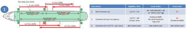
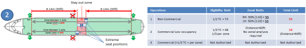
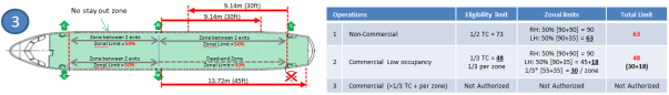
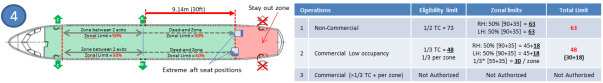
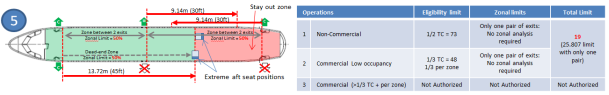
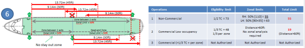
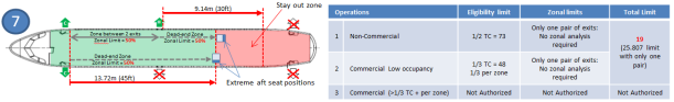
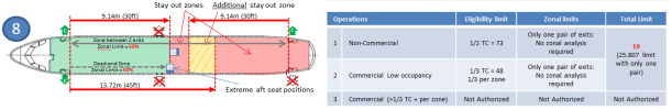
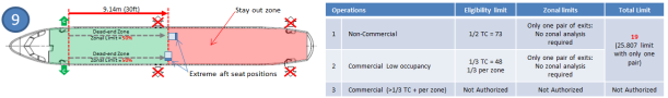
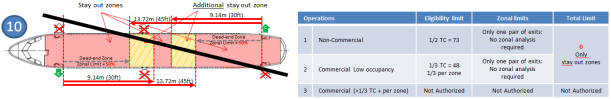
[Amdt 25/19]
ED Decision 2017/015/R
(a) Flammability Requirements
(1) Mattresses of permanent bed installations that are located in compartments isolated from the main passenger cabin by doors or equivalent means that would normally be closed during taxiing, take-off, and landing do not need to meet the ‘Oil Burner Test’ requirement of Appendix F, Part II as required by CS 25.853(c) (See AMC to Appendix S, S25.20(a)(1)).
(2) On non-commercially operated aeroplanes only, compliance with CS 25.853(d) does not need to be demonstrated if it can be shown by test or a combination of test and analysis under the conditions specified in Appendix J that the maximum time for evacuation of all occupants does not exceed 45 sec.
(b) Access to Type III and IV Emergency Exits: low-occupancy aeroplanes that have a passenger seating configuration of 19 or less and non-commercially operated aeroplanes may have an item deployable into the region defined by CS 25.813 (c)(4)(i) or CS 25.813 (c)(1), (2) or (3) which creates an obstruction and, therefore, leads to non-compliance with one or more of the aforementioned requirements, provided that:
(1) it is ensured that the item will be safely stowed before entering any of the taxiing, take-off, approach, and landing phases, by means of a position monitoring and alerting system that, in a timely manner, notifies the flight crew and compels the passengers to stow the item if it is in a position that creates an obstruction (See AMC to Appendix S, S25.20(b)(1)). It must be substantiated that, with the item in its most adverse position(s), the remaining exit is at least as effective as a Type IV emergency exit, unless it can be shown that following any single failure, an exit at least as effective as a Type IV emergency exit can be obtained by simple and obvious means; or
(2) the approved passenger configuration is such that this number of passengers can be evacuated through the exit in question, with the obstruction in its most adverse position and under the conditions of Appendix J, at least as quickly as the maximum number of passengers allowed by CS 25.807(g) without the obstruction. It must be substantiated that, with the obstruction in place, the remaining exit is at least as effective as a Type IV emergency exit; or
(3) for aeroplanes required to have at least one cabin crew member on board, the item is intended for use only by a cabin crew member that has direct view of the deployable item and can confirm that it is correctly stowed and secured, while they are seated during taxiing, take-off, and landing.
[Amdt 25/19]
AMC to Appendix S, S25.20(a)(1) Flammability of Bed Mattresses
ED Decision 2017/015/R
Mattresses of beds that are convertible to/from seats, regardless of their location in the aeroplane, and irrespective of whether or not the seat configuration is approved for occupancy during taxiing, take-off, and landing, should meet the criteria of CS-25, Appendix F, Part II.
As required by CS-25, Appendix F, mattress foam shall be tested for 12,7-mm (1/2-in.) thickness. If the mattress consists of two or more foams glued together, the foam specimen should consist of two 6.34-mm (1/4-in.) (three layers of 4.2 mm (1/6 in.), etc.) pieces glued together. Three specimens should be made for each combination of foams that are glued together in the production mattress. Any other production mattress components that are glued together should also be tested together.
If such specimens do not meet the test criteria of CS-25, Appendix F, Part I, it is acceptable to test each production mattress component separately, including a sheet of glue, using the test criteria of Appendix F, Part I.
Additionally, the Bunsen burner is then to be applied at three separate corners of the production mattress with all its components. The three-corner test does not need to be conducted if the cushion passes the tests of CS-25, Appendix F, Part II.
[Amdt 25/19]
AMC to Appendix S, S25.20(b) Exit as effective as a Type IV exit
ED Decision 2017/015/R
An acceptable means of compliance with the requirement that the remaining exit resulting from an obstruction shall be as effective as a Type IV emergency exit (S25.20(b)(1) and (b)(2)), is to demonstrate that:
(1) the dimensions of the remaining exit opening are equivalent to or greater than those of a Type IV emergency exit; and
(2) the obstructing item does not protrude into the horizontally projected opening of the remaining exit.
In the assessment of the effectiveness of the remaining exit, the requirements of CS 25.807(a)(4), CS 25.809(b) and CS 25.813(c)(1) should also be considered.
[Amdt 25/19]
ED Decision 2017/015/R
This paragraph provides guidelines regarding the criteria under which an item, although constituting an obstruction that does not comply to CS 25.813(c), may be considered acceptable because per design and procedure, there can be high confidence that the obstruction will be removed when needed for safety (S25.20(b)(1)).
In addition to the exceptions set in Section 2 — Deployable features of AMC 25.813(c), an item which can be deployed by a crew member or passenger into the region defined by CS 25.813 (c)(4)(i) or into the passageway required by CS 25.813 (c)(1), (2) or (3), but which, when stowed, is no longer in either of these areas, is acceptable if there is enough assurance that the item will be stowed when needed. Such assurance may be assumed when all following conditions are met:
(1) A position monitoring system is installed, which detects that the item is not properly stowed, and triggers both alerts in the passenger cabin and a visual indication to the flight crew if the item is not properly stowed before entering any of the taxiing, take-off, approach, and landing phases.
(2) The alerts in the cabin, required in paragraph (1), include an aural device which sounds continuously in all areas of the passenger cabin (it should be loud enough to clearly act as an irritant, thus assuring that occupants will stow the obstruction, but not so loud as to distract the flight crew), as well as a conspicuous electrically illuminated sign showing an appropriate text message or pictogram, in the immediate proximity of the relevant emergency exit.
(3) The alerts described in paragraph (2), are triggered without delay if the deployable item is moved away from the safe position during any of the taxiing, take-off, approach, and landing flight phases, or, if upon entering these phases, the item is not stowed in the safe position. When preparing for landing, the alerts are triggered at a point that allows ample time for a cabin occupant to re-stow the deployable item before landing. It should be considered that the cabin occupant needs to move within the cabin to reach the deployable item, therefore, the alerts should be triggered during descent, allowing enough time prior to entering the approach phase, unless the aeroplane is required to have at least one cabin crew member on board; The aural and visual alerts should both remain on until the obstacle is properly stowed.
(4) The visual indication provided to the flight crew, described in paragraph (1), is triggered without delay if the deployable item is moved away from the safe position during any of the taxiing, take-off, approach, and landing flight phases, or, if upon entering these phases, the deployable item is not stowed in the safe position. When preparing for landing, the visual indication is triggered during the descent phase, early enough to enable the crew to take appropriate action before entering the approach phase.
(5) The failure to alert in the cabin or cockpit that an item is not properly stowed is demonstrated to have an average probability per flight hour of the order of 1 x 10⁻³ or less.
(6) Instructions are given to the passengers and cabin crew (if any), by means of appropriate placards and a pre-flight briefing, that the obstacle should be stowed before entering any of the taxiing, take-off, approach, and landing phases. The pre-flight briefing (which could be part of a regular briefing) should describe the position monitoring and alerting system, as well as the necessary response by the passengers. The requirement for this briefing should be part of the AFM.
(7) A description of the position monitoring and alerting system is made available to the flight crew. The AFM should also include the appropriate normal procedure ensuring that the cabin is ready (i.e. a check that no visual indication, as defined in paragraph (4), being present) prior to landing, and an instruction that the crew takes all necessary actions when the visual indication, as defined in paragraph (4), is triggered.
(8) The emergency exit provided when the obstruction in its most adverse position(s) is at least as effective as a Type IV emergency exit, unless it can be shown that following any single failure an exit at least as effective as a Type IV emergency exit can be obtained by simple and obvious means. If the obstructing item is a seat, the normal seat operating controls (e.g. track, swivel, recline etc.) may be considered as means meeting the simple and obvious requirement, provided that the controls remain visible to a person approaching the seat and are easily useable without sitting on the seat, when the seat is in any possible obstructing condition. If movement of the obstructing item to meet the above requires electrical power, it should be substantiated that the required power source(s) will remain available following an emergency landing.
[Amdt 25/19]
AMC to Appendix S, S25.20(b)(2) Comparative assessment of evacuation capability
ED Decision 2020/024/R
Use of the Latin square method as detailed in Appendix 4 to FAA Advisory Circular (AC) 25‑17A Change 1 Transport Airplane Cabin Interiors Crashworthiness Handbook, dated 24.5.2016 is accepted by EASA as providing acceptable means of compliance with S25.20(b)(2).
[Amdt 25/19]
[Amdt 25/26]
S25.30 Circulation Inside Cabin During Flight
ED Decision 2017/015/R
(a) Width of Aisle: for low-occupancy aeroplanes that have a passenger seating configuration of 19 or less, and for non-commercially operated aeroplanes, the design must be such that the dimensional requirements of CS 25.815 can be achieved during all flight phases, except that the width of aisle may be reduced to 0 m during in-flight operations provided that compliance with the following additional requirements is shown (See AMC to Appendix S, S25.30(a)):
(1) all areas of the cabin must be easily accessible by passengers or crew in the event of an emergency situation (e.g. in-flight fire, depressurisation);
(2) placard instructions for restoring the aisle to the taxiing, take-off, and landing configuration must be provided at the locations where the width of the cabin aisle is reduced; and
(3) procedures must be established and documented in the AFM for restoring the aisle width for taxiing, take-off, and landing.
(b) Firm Handholds: in lieu of the requirements of CS 25.785(j), if the seat backs do not provide a firm handhold, there must be an acceptable means to enable persons to steady themselves while using the aisles in moderately rough air (See AMC to Appendix S, S25.30(b)).
[Amdt 25/19]
AMC to Appendix S, S25.30(a) Width of Aisle
ED Decision 2017/015/R
For compliance with the ‘Width of Aisle’ requirement, the following applies:
(1) An obstacle in the passageway is considered easily surmountable if the aisle width reduction it creates may be negotiated by a person anywhere in the size range from 5th percentile female to a 95th percentile male.
(2) Negotiating of an obstacle may require the removal and/or movement of more than one item.
(3) If an obstacle is stepped on, it should be capable of withstanding without failure a vertical step force of 222 daN (500 lbs) applied at the most adverse stepping location, without failure to the extent that it could unsteady a person trying to surmount that obstacle.
(4) When assessing compliance, the applicant should select the most adverse in-flight configuration(s). The selection should include all possibilities regardless of subjective issues, such as the likelihood that passengers may consider the configuration advantageous. If however, an applicant feels that one or more configurations, although possible, would only result from severely anomalous behaviour by cabin occupants, it/they may be justified for elimination from the assessment. The configuration(s) should be highlighted and their elimination justified in the assessment report, for Agency agreement. The possibility of entrapment (e.g. feet, hands etc.) during negotiating of the obstacle should be included in the assessment and selection of adverse in-flight configurations. Maintaining gaps of less than 3.5 cm (1.38 in.) is considered acceptable to eliminate the risk of entrapment. Items such as drawers or stowage doors do not need to be considered opened in the aisle. Each interior door may be considered open unless another position of the door might interact with the movement of an obstacle out of the aisle. In that case, all possible interactions between the door and the obstacle should be assessed. In general, items need only be considered in their most adverse detent or locked position.
(5) For the purpose of showing compliance, the applicant may use tests, analyses supported by test data, or, where appropriate, inspections.
(6) In principle, the total time required for a crew member to travel from the forwardmost point in the cabin to the rearmost point, with all aisle obstacles in their most adverse positions, should not exceed by more than 30 seconds the time it would take without the obstacles in place. However, the cabin may be divided into zones, provided that each zone includes the quantity and type of emergency equipment adequate for firefighting, and that it can be substantiated that at least one cabin crew member is likely to occupy that zone during the majority of the flight. It should be shown that the time required for a cabin crew member to travel from the forwardmost point to the rearmost point of each zone, with all aisle obstacles in their most adverse positions, will not exceed by more than 30 seconds the time it would take without the obstacles in place.
(7) If an unobstructed passageway exists as an alternative to the obstructed one (e.g. aeroplanes with two aisles), it may be acceptable for this alternative route to be used when showing compliance. Such acceptability will depend on a case-by-case assessment of the degree to which such an alternative route would be obvious to the crew member.
Note: interior doors are not addressed by the requirements of S25.30(a) but rather by the requirements of S25.10(a) and (b).
[Amdt 25/19]
AMC to Appendix S, S25.30(b) Firm Handholds
ED Decision 2017/015/R
Where the cabin layout is similar to a standard airline layout, firm handholds as normally expected for such seating areas should be provided.
Where closely spaced firm handholds cannot be easily provided, the ‘Firm Handholds’ requirement can be considered as complied with, provided the following conditions are met:
(1) there should be a recommendation to passengers to remain seated with seat belts fastened, which may be a placard or a required (i.e. specified in the AFM) pre-flight briefing;
(2) there should be at least one route through each area that provides firm handholds to enable passengers to reach their designated seats; in these areas:
(a) firm handholds should be mounted at least 66 cm (26 in.) high; and
(b) the distance between firm handholds should not be greater than 2.15 m (84 in.);
(3) wherever aisles are not bordered by seats, it is acceptable that occupants may steady themselves by leaning on sidewalls or other interior components; and
(4) in any case, the applicant shall demonstrate that items used as firm handholds are structurally adequate to perform this function.
[Amdt 25/19]
ED Decision 2017/015/R
(a) ‘No Smoking’ Placards and Lavatory Ashtrays: if smoking is to be prohibited, in lieu of the requirements of CS 25.791(a) and CS 25.791(d), a reduced number of ‘No smoking’ placards may be provided and lavatory ashtrays do not need to be provided in accordance with the following:
(1) a ‘No smoking’ placard must be conspicuously located inside the passenger compartment in the immediate vicinity of each door that can be used as a passenger boarding door. Each placard must be clearly legible for passengers entering the aeroplane;
(2) compliance with CS 25.853(g) is not required; and
(3) the indication that smoking is prohibited must be the subject of a passenger briefing, and the requirement for this briefing must be part of the AFM.
(b) Briefing Card Placard: for non-commercially operated aeroplanes, the instructions required by CS 25.1541 for properly setting the cabin in its configuration approved for taxiing, take-off, and landing may alternatively be provided by a reduced number of placards, each one referring to a briefing card. In that case (See AMC to Appendix S, S25.40(b)):
(1) the detailed minimum instructions to be included in the briefing card must be part of the type design and referred to in the ‘Limitations’ section of the AFM; and
(2) the briefing card must be easily accessible from each passenger seat. A dedicated stowage must be provided to stow the briefing card within easy reach of each seated passenger with their seat belts fastened.
(c) Seats in Excess (See AMC to Appendix S, S25.40(c))
(1) If the total number of seats that are approved for occupancy during taxiing, take-off, and landing is greater than the approved passenger seating configuration, the difference between these two quantities is deemed to be seats in excess. If seats in excess exist, a placard indicating the approved passenger seating configuration must be installed adjacent to each door that can be used as a passenger boarding door. This placard must be clearly legible for passengers entering the aeroplane. Additionally, a note must be included in the ‘Limitations’ section of the AFM stating that there are excess seats installed, and indicating the maximum number of passengers that may be transported.
(2) For each seating location available for in-flight use only (including in-flight-only seats, beds, berths, and divans), a placard indicating that the location is not to be occupied during taxiing, take-off, and landing must be installed such that the placard is legible to the seated occupant.
[Amdt 25/19]
AMC to Appendix S, S25.40(b) Briefing Card Placard
ED Decision 2017/015/R
The instructions that may be reported on the briefing card referred to in S25.40(b) are limited to the instructions necessary to restore the configuration of the passenger cabin to that approved for taxiing, take-off, and landing. All other placards required by CS-25 are excluded from the provisions of S25.40(b).
For example, and where applicable, a briefing card may be used to deliver information related to setting seats in the upright position, stowing leg rests/armrests, repositioning ‘high–low’ position tables, opening/closing doors, installing crash pads, etc.
The content added to the briefing card to cover information conventionally conveyed via placarding, and the means to provide accessibility to this information will need to be approved as part of the type design. However, it may be desired to include additional safety information on the same briefing card. This may be due to operational requirements for a briefing card, or may be at the applicant’s or customer’s discretion. This is acceptable, and this additional information will not be subject to approval as part of the type design.
However, limitations on the presentation of this additional information on the briefing card (e.g. size, style, relative location) may need to be stated in the type design in order that both sets of information remain appropriately conspicuous to the passengers.
When design solutions are proposed using placards that make reference to a briefing card for further instructions, the following should be considered:
(1) Individual placards at each seat location may be replaced by a simplified placard referring to the briefing card. For example: ‘Refer to the briefing card to configure cabin/seat/table/leg rest for taxiing, take-off, and landing’.
(2) Alternatively, one single placard stating, for example, ‘Moveable items in this area should be configured in accordance with the briefing card for taxiing, take-off, and landing’, and visible from each seated position of a group of seats, may be used.
(3) The briefing card should be demonstrated to be accessible from each passenger seat. A dedicated stowage (e.g. pocket) easily recognisable by a seated passenger, or when approaching the seat, shall be provided. The briefing card should be within easy reach of each passenger with their seat belt fastened, except in some cases where this may be impracticable. For instance, it may be acceptable that a passenger occupying the centre place of a three-place divan is not able to reach the briefing card with their seat belt fastened. In such a case, EASA may accept that either the left hand (LH) or right hand (RH) place of the divan will most likely be occupied, and that this passenger’s access to the briefing card will provide him/her with the required awareness of necessary pre-flight and landing actions.
(4) The briefing card information should be clear and simple. It is expected that the additional space offered by the briefing card, relative to conventional placarding, will allow applicants to provide more easily understood safety instructions. The use of pictograms is encouraged.
[Amdt 25/19]
AMC to Appendix S, S25.40(c) Seats in Excess
ED Decision 2017/015/R
S25.40(c) requires the installation of a placard, adjacent to each possible passenger boarding door, on aeroplanes which have a greater number of seats approved for occupancy during taxiing, take-off, and landing than the approved passenger seating configuration. It may be acceptable that the selection of which seats to occupy is at the operator’s/passenger’s discretion, or constraints may exist for instance due to the zonal limitations set by S25.1(a)(2), or the varying passenger seating configuration and/or direct-view limitations for an aeroplane with different, reconfigurable, cabin designs approved for private versus commercial transport operations. In such cases, the placard should indicate limitations of the allowable seating occupancy for taxiing, take-off, and landing, as appropriate, for each cabin zone, and not just for the aeroplane as a whole; moreover, different indications should be provided with reference to the different type of operations that may be performed (non-commercial/commercial).
Additionally, if it is decided to help passengers in selecting acceptable seating locations by means of markings on a seat or seats, a local placard (text or symbolic), easily readable by a passenger approaching/seated on each such seat, should be provided. The placard should be of adequate size for easy readability.
[Amdt 25/19]
S25.50 Cabin Attendant Direct View
ED Decision 2017/015/R
In lieu of the requirements of CS 25.785(h)(2), compliance with the following cabin attendant direct view requirements may be shown:
(a) For non-commercially operated aeroplanes, at least half of the installed cabin crew member seats must face the passenger cabin.
(b) For low-occupancy aeroplanes, cabin crew member seats must be, to the extent possible, without compromising proximity to a required floor level emergency exit, located to provide direct view of the cabin area for which the cabin crew member is responsible (See AMC to Appendix S, S25.50(b)).
[Amdt 25/19]
AMC to Appendix S, S25.50(b) Cabin Attendant Direct View
ED Decision 2017/015/R
For commercial operations, compliance with CS 25.785(h)(2) may be shown based on the criteria of FAA AC 25.785-1B, Flight attendant seat and torso restraint system installations, 11 May 2010, with the following deviations from Section 10 thereof:
(1) Subparagraph 10a(2) is amended to read as follows:
‘(2) Each floor level emergency exit adjacent to a required crew member seat’;
(2) Subparagraph 10a(3) is amended to read as follows;
‘(3) At least 50 % of the total number of passenger seats authorised for occupancy during taxiing, take-off, and landing.’;
(3) Subparagraph 10a(4) is amended to read as follows:
‘(4) At least 25 % of the passenger seats in each visually divided zone of four or more passenger seats.’; and
(4) Subparagraph 10b(3)(a) is amended to read as follows:
‘(a) A person seated in the seat is visible when they make any upper-body movement, such as moving their arm over their head or sideways, including leaning, while belted on their seat.’.
[Amdt 25/19]
ED Decision 2018/005/R
Non-commercially operated aeroplanes do not need to comply with the security specifications of CS 25.795(b), (c) and (d).
[Amdt 25/21]