
Part I – Atmospheric Icing Conditions
ED Decision 2007/010/R
(a) Continuous maximum icing. The maximum continuous intensity of atmospheric icing conditions (continuous maximum icing) is defined by the variables of the cloud liquid water content, the mean effective diameter of the cloud droplets, the ambient air temperature, and the interrelationship of these three variables as shown in Figure 1 of this Appendix. The limiting icing envelope in terms of altitude and temperature is given in Figure 2 of this Appendix. The interrelationship of cloud liquid water content with drop diameter and altitude is determined from Figures 1 and 2. The cloud liquid water content for continuous maximum icing conditions of a horizontal extent, other than 32.2 km (17·4 nautical miles), is determined by the value of liquid water content of Figure 1, multiplied by the appropriate factor from Figure 3 of this Appendix.
(b) Intermittent maximum icing. The intermittent maximum intensity of atmospheric icing conditions (intermittent maximum icing) is defined by the variables of the cloud liquid water content, the mean effective diameter of the cloud droplets, the ambient air temperature, and the interrelationship of these three variables as shown in Figure 4 of this Appendix. The limiting icing envelope in terms of altitude and temperature is given in Figure 5 of this Appendix. The interrelationship of cloud liquid water content with drop diameter and altitude is determined from Figures 4 and 5. The cloud liquid water content for intermittent maximum icing conditions of a horizontal extent, other than 4.8 km (2·6 nautical miles), is determined by the value of cloud liquid water content of Figure 4 multiplied by the appropriate factor in Figure 6 of this Appendix.
(c) Takeoff maximum icing. The maximum intensity of atmospheric icing conditions for takeoff (takeoff maximum icing) is defined by the cloud liquid water content of 0.35 g/m3, the mean effective diameter of the cloud droplets of 20 microns, and the ambient air temperature at ground level of minus 9 degrees Celsius (-9 C). The takeoff maximum icing conditions extend from ground level to a height of 457 m (1500 ft) above the level of the takeoff surface.
[Amdt 25/3]
Part II – Airframe Ice Accretions
ED Decision 2015/008/R
(a) Ice accretions - General. The most critical ice accretion in terms of aeroplane performance and handling qualities for each flight phase must be used to show compliance with the applicable aeroplane performance and handling requirements in icing conditions of subpart B of this part. Applicants must demonstrate that the full range of atmospheric icing conditions specified in part I of this appendix have been considered, including the mean effective drop diameter, liquid water content, and temperature appropriate to the flight conditions (for example, configuration, speed, angle-of-attack, and altitude). The ice accretions for each flight phase are defined as follows:
(1) Take-off Ice is the most critical ice accretion on unprotected surfaces, and any ice accretion on the protected surfaces appropriate to normal ice protection system operation, occurring between the end of the take-off distance and 122 m (400 ft) above the take-off surface, assuming accretion starts at the end of the take-off distance in the take-off maximum icing conditions of Part I, paragraph (c) of this Appendix.
(2) Final Take-off Ice is the most critical ice accretion on unprotected surfaces, and any ice accretion on the protected surfaces appropriate to normal ice protection system operation, between 122 m (400 ft) and either 457 m (1500 ft) above the take-off surface, or the height at which the transition from the take-off to the en route configuration is completed and VFTO is reached, whichever is higher. Ice accretion is assumed to start at the end of the take-off distance in the take-off maximum icing conditions of Part I, paragraph (c) of this Appendix.
(3) En-route Ice is the critical ice accretion on the unprotected surfaces, and any ice accretion on the protected surfaces appropriate to normal ice protection system operation, during the en-route phase.
(4) Holding Ice is the critical ice accretion on the unprotected surfaces, and any ice accretion on the protected surfaces appropriate to normal ice protection system operation, during the holding flight phase.
(5) Approach ice is the critical ice accretion on the unprotected surfaces, and any ice accretion on the protected surfaces appropriate to normal ice protection system operation following exit from the holding flight phase and transition to the most critical approach configuration.
(6) Landing ice is the critical ice accretion on the unprotected surfaces, and any ice accretion on the protected surfaces appropriate to normal ice protection system operation following exit from the approach flight phase and transition to the final landing configuration.
(b) In order to reduce the number of ice accretions to be considered when demonstrating compliance with the requirements of paragraph CS 25.21(g), any of the ice accretions defined in sub-paragraph (a) of this section may be used for any other flight phase if it is shown to be more critical than the specific ice accretion defined for that flight phase. Configuration differences and their effects on ice accretions must be taken into account.
(c) The ice accretion that has the most adverse effect on handling characteristics may be used for aeroplane performance tests provided any difference in performance is conservatively taken into account.
(d) For both unprotected and protected parts, the ice accretion for the takeoff phase may be determined by calculation, assuming the takeoff maximum icing conditions defined in appendix C, and assuming that:
(1) Airfoils, control surfaces and, if applicable, propellers are free from frost, snow, or ice at the start of the take-off;
(2) The ice accretion starts at the end of the take-off distance;
(3) The critical ratio of thrust/power-to-weight;
(4) Failure of the critical engine occurs at VEF; and
(5) Crew activation of the ice protection system is in accordance with a normal operating procedure provided in the Aeroplane Flight Manual, except that after beginning the takeoff roll, it must be assumed that the crew takes no action to activate the ice protection system until the airplane is at least 122 m (400 ft) above the takeoff surface.
(e) The ice accretion before the ice protection system has been activated and is performing its intended function is the critical ice accretion formed on the unprotected and normally protected surfaces before activation and effective operation of the ice protection system in continuous maximum atmospheric icing conditions. This ice accretion only applies in showing compliance to CS 25.143(j), 25.207(h) and 25.207(i).
[Amdt 25/3]
[Amdt 25/7]
[Amdt 25/16]
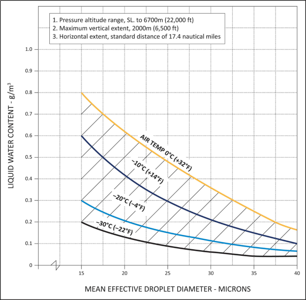
FIGURE 1
CONTINUOUS MAXIMUM (STRATIFORM CLOUDS) ATMOSPHERIC ICING CONDITIONS
LIQUID WATER CONTENT VS MEAN EFFECTIVE DROP DIAMETER
Source of data – NACA TN No. 1855, Class III –M, Continuous Maximum.
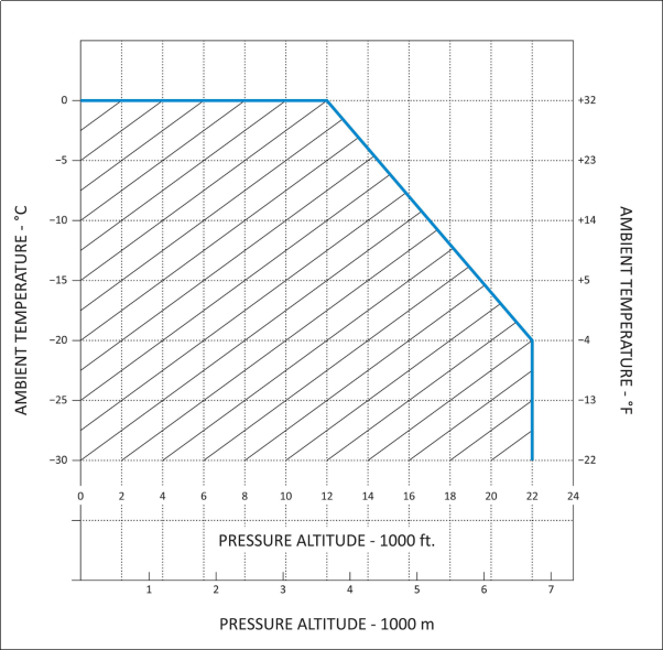
FIGURE 2
CONTINUOUS MAXIMUM (STRATIFORM CLOUDS) ATMOSPHERIC ICING CONDITIONS
AMBIENT TEMPERATURE VS PRESSURE ALTITUDE
Source of data – NACA TN No. 2569.
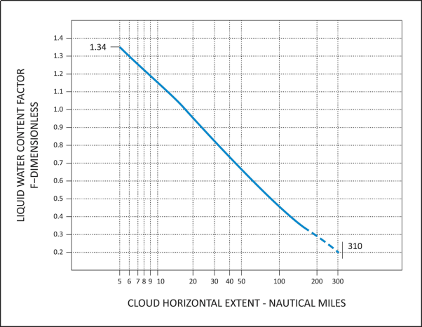
FIGURE 3
CONTINUOUS MAXIMUM (STRATIFORM CLOUDS) ATMOSPHERIC ICING CONDITIONS
LIQUID WATER CONTENT FACTOR VS CLOUD HORIZONTAL DISTANCE
Source of data – NACA TN No. 2738.
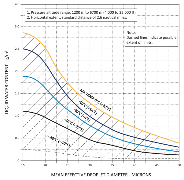
FIGURE 4
INTERMITTENT MAXIMUM (CUMULIFORM CLOUDS) ATMOSPHERIC ICING CONDITIONS
LIQUID WATER CONTENT VS MEAN EFFECTIVE DROP DIAMETER
Source of data – NACA TN No. 1855, Class II – M, Intermittent Maximum
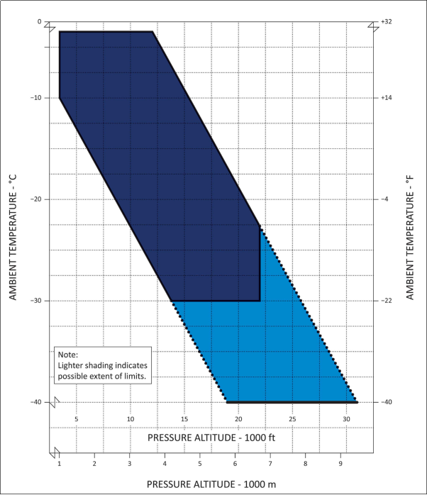
FIGURE 5
INTERMITTENT MAXIMUM (CUMULIFORM CLOUDS) ATMOSPHERIC ICING CONDITIONS
AMBIENT TEMPERATURE VS PRESSURE ALTITUDE
Source of data – NACA TN No. 2569.
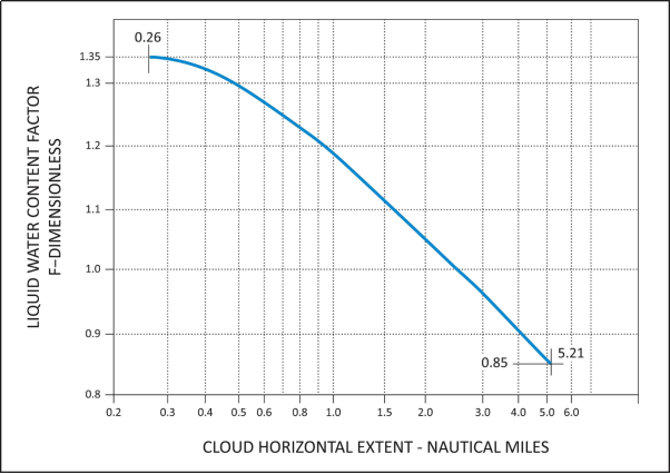
FIGURE 6
INTERMITTENT MAXIMUM (CUMULIFORM CLOUDS) ATMOSPHERIC ICING CONDITIONS
VARIATION OF LIQUID WATER CONTENT FACTOR WITH CLOUD HORIZONTAL EXTENT
Source of data – NACA TN No. 2738.
Appendix D
ED Decision 2003/2/RM
Criteria for determining minimum flight crew. The following are considered by the Agency in determining the minimum flight crew under CS 25.1523.
(a) Basic workload functions. The following basic workload functions are considered:
(1) Flight path control.
(2) Collision avoidance.
(3) Navigation.
(4) Communications.
(5) Operation and monitoring of aircraft engines and systems.
(6) Command decisions.
(b) Workload factors. The following workload factors are considered significant when analysing and demonstrating workload for minimum flight crew determination:
(1) The accessibility, ease and simplicity of operation of all necessary flight, power, and equipment controls, including emergency fuel shutoff valves, electrical controls, electronic controls, pressurisation system controls, and engine controls.
(2) The accessibility and conspicuity of all necessary instruments and failure warning devices such as fire warning, electrical system malfunction, and other failure or caution indicators. The extent to which such instruments or devices direct the proper corrective action is also considered.
(3) The number, urgency, and complexity of operating procedures with particular consideration given to the specific fuel management schedule imposed by centre of gravity, structural or other considerations of an airworthiness nature, and to the ability of each engine to operate at all times from a single tank or source which is automatically replenished if fuel is also stored in other tanks.
(4) The degree and duration of concentrated mental and physical effort involved in normal operation and in diagnosing and coping with malfunctions and emergencies.
(5) The extent of required monitoring of the fuel, hydraulic, pressurisation, electrical, electronic, deicing, and other systems while en route.
(6) The actions requiring a crew member to be unavailable at his assigned duty station, including: observation of systems, emergency operation of any control, and emergencies in any compartment.
(7) The degree of automation provided in the aircraft systems to afford (after failures or malfunctions) automatic crossover or isolation of difficulties to minimise the need for flight crew action to guard against loss of hydraulic or electrical power to flight controls or other essential systems.
(8) The communications and navigation workload.
(9) The possibility of increased workload associated with any emergency that may lead to other emergencies.
(10) Incapacitation of a flight-crew member whenever the applicable operating rule requires a minimum flight crew of at least two pilots.
(c) Kind of operation authorised. The determination of the kind of operation authorised requires consideration of the operating rules under which the aeroplane will be operated. Unless an applicant desires approval for a more limited kind of operation, it is assumed that each aeroplane certificated under this CS-25 will operate under IFR conditions.