
ED Decision 2016/010/R
(See AMC 25.851)
(a) Hand fire extinguishers. (See AMC 25.851(a).)
(1) The following minimum number of hand fire extinguishers must be conveniently located and evenly distributed in passenger compartments. (See AMC 25.851(a)(1).):
|
Passenger capacity |
Number of extinguishers |
|
7 to 30 |
1 |
|
31 to 60 |
2 |
|
61 to 200 |
3 |
|
201 to 300 |
4 |
|
301 to 400 |
5 |
|
401 to 500 |
6 |
|
501 to 600 |
7 |
|
601 to 700 |
8 |
(2) At least one hand fire extinguisher must be conveniently located in the pilot compartment (see AMC 25.851(a)(2)).
(3) At least one readily accessible hand fire extinguisher must be available for use in each Class A or Class B cargo or baggage compartment and in each Class E or Class F cargo or baggage compartment that is accessible to crewmembers in flight.
(4) At least one hand fire extinguisher must be located in, or readily accessible for use in, each galley located above or below the passenger compartment.
(5) Each hand fire extinguisher must be approved.
(6) The required fire extinguishers located in the passenger compartment must contain an accepted extinguishing agent that is appropriate for the kinds and classes of fires likely to occur where used.
(7) The quantity of extinguishing agent used in each extinguisher required by this paragraph must be appropriate for the kinds of fires likely to occur where used.
(8) Each extinguisher intended for use in a personnel compartment must be designed to minimise the hazard of toxic gas concentration.
(b) Built-in fire extinguishers. If a built-in fire extinguisher is provided –
(1) Each built-in fire extinguishing system must be installed so that –
(i) No extinguishing agent likely to enter personnel compartments will be hazardous to the occupants; and
(ii) No discharge of the extinguisher can cause structural damage.
(2) The capacity of each required built-in fire extinguishing system must be adequate for any fire likely to occur anywhere in the compartment where used, considering the volume of the compartment and the ventilation rate. (see AMC 25.851(b)).
(c) Fire-extinguishing agents
(See AMC 25.851(c))
(1) Fire classes against which fire-extinguishing agents may be employed are:
— Class A: Fires involving ordinary combustible materials, such as wood, cloth, paper, rubber and plastics;
— Class B: Fires involving flammable liquids, petroleum oils, greases, tars, oil base paints, lacquers, solvents, alcohols and flammable gases;
— Class C: Fires involving energised electrical equipment where the use of an extinguishing agent that is electrically non-conductive is important.
[Amdt 25/4]
[Amdt 25/8]
[Amdt 25/12]
[Amdt 25/18]
AMC 25.851(a) Hand fire extinguishers
ED Decision 2012/008/R
1 Each extinguisher should be readily accessible and mounted so as to facilitate quick removal from its mounting bracket.
2 Unless an extinguisher is clearly visible, its location should be indicated by a placard or sign having letters of at least 9.5 mm (0·375) inches in height on a contrasting background. Appropriate symbols may be used to supplement such a placard or sign.
[Amdt 25/12]
AMC 25.851(a)(1) Hand fire extinguishers
ED Decision 2012/008/RM
1 The number and location of hand fire extinguishers should be such as to provide adequate availability for use, account being taken of the number and size of the passenger compartments and the location of toilets, galleys, etc. These considerations may result in the number being greater than the minimum prescribed.
2 Where only one hand extinguisher is required it should be located at the cabin crew member station, where provided, otherwise near the main entrance door.
3 Where two or more hand extinguishers are required and their location is not otherwise dictated by consideration of paragraph 1 above, an extinguisher should be located at each end of the cabin and the remainder distributed throughout the cabin as evenly as is practicable.
[Amdt 25/12]
AMC 25.851(a)(2) Hand fire extinguishers
ED Decision 2012/008/R
There should be at least one fire extinguisher suitable for Class B and C fires installed in each pilot’s compartment. Additional extinguishers may be required for the protection of other compartments accessible to the crew in flight (e.g. electrical equipment bays) or from consideration of CS 25.851(a)(2).
Based on EU legislation5 Commission Regulation (EU) No 744/2010 of 18 August 2010 amending Regulation (EC) No 1005/2009 of the European Parliament and of the Council on substances that deplete the ozone layer, with regard to the critical uses of halon (OJ L 218, 19.8.2010, p. 2)., for new installations of hand fire extinguishers for which the certification application is submitted after 31 December 2014, Halon 1211, 1301 and Halon 2402 are unacceptable extinguishing agents.
The hand fire extinguishers and related agents listed in the FAA Advisory Circular AC 20-42D are considered acceptable by the Agency. See AMC 25.851(c) for more information on Halon alternatives.
NOTE: Dry chemical fire extinguishers should not be used in pilot compartments because of the adverse effects on vision during discharge and, if non-conductive, interference with electrical contacts by the chemical residues.
[Amdt 25/12]
AMC 25.851(b) Built-in Fire Extinguishers for Cargo Compartments
ED Decision 2012/008/R
1. PURPOSE.
This AMC sets forth acceptable means, but not the only means, of demonstrating compliance with the provisions of CS-25 related to the built-in fire suppression systems when required for cargo compartments of large aeroplanes. The guidance provided within this AMC has been found acceptable for showing compliance with the provisions of CS 25.855 and 25.857 for built-in fire-extinguishing systems. As with all AMC material, it is not mandatory and does not constitute a regulation. For application to the product, alternate methods may be elected to be followed, provided that these methods are also found by the EASA to be an acceptable means of complying with the requirements of CS-25.
2. RELATED CS PARAGRAPHS.
CS 25.851 "Fire extinguishers"
CS 25.855 "Cargo or baggage compartments"
CS 25.857 "Cargo compartment classification”
CS 25.858 "Cargo compartment fire detection systems”
3. BAN ON HALON 1301.
Halon 1301 is no longer an acceptable extinguishing agent, based on EU Legislation6 Commission Regulation (EU) No 744/2010 of 18 August 2010 amending Regulation (EC) No 1005/2009 of the European Parliament and of the Council on substances that deplete the ozone layer, with regard to the critical uses of halon (OJ L 218, 19.8.2010, p. 2)., for cargo compartment fire extinction systems to be installed on aircraft types, for which type certification is requested after 31 December 2018. See AMC 25.851(c) for more information on Halon alternatives.
4. BACKGROUND ON CONCENTRATION OF HALON 1301.
Minimal written guidance is available for use in certifying cargo compartment fire-extinguishing or suppression systems. Testing at the FAA Technical Center and other data from standardised fire-extinguishing evaluation tests indicates that the use of averaging techniques may not substantiate that there are adequate concentration levels of fire-extinguishing agent throughout the compartment to effectively suppress a cargo fire.
Cargo fire-extinguishing systems installed in aeroplanes have primarily used Halon 1301 as the fire suppression agent. One widely used method to certify Halon 1301 cargo fire suppression systems requires an initial concentration of five percent by volume in order to knock down a cargo fire. Subsequent concentration levels should not drop below three percent by volume for the remainder of the flight in order to suppress a cargo fire until it can be completely extinguished by ground personnel following a safe landing.
Since Halon 1301 is approximately five times heavier than air, it tends to stratify and settle after it is released into the cargo compartment. Also, due to temperature differences and ventilation patterns, in a ventilated compartment, Halon 1301 will start to stratify shortly after discharge and the concentration level will decay faster in the upper locations of the compartment than in the lower locations. Halon 1301 will also have a tendency to move aft due to any upward pitch or forward in any downward pitch of the aeroplane in flight. For some products the concentration levels of Halon 1301 have been measured at various locations throughout the cargo compartment and used an arithmetic average of the individual sampling locations to determine an overall concentration level for the cargo compartment. This averaging technique may allow the concentration level to drop below three percent by volume at individual sampling locations near the top of the cargo compartment.
Testing at the FAA Technical Center and other data from standardised fire-extinguishing evaluation tests indicates that the use of averaging techniques may not substantiate that there are adequate concentration levels of fire-extinguishing agent throughout the compartment to effectively suppress a cargo fire. If a cargo fire occurred, and was subsequently suppressed by Halon 1301, the core of the fire could remain hot for a period of time. If the local concentration of Halon 1301 in the vicinity of the fire core dropped below three percent by volume and sufficient oxygen is available, re-ignition could occur. The FAA tests have shown that when the Halon 1301 concentration level drops below three percent by volume and the cargo fire re-ignites, the convective stirring caused by the heat of the fire may be insufficient to raise the local concentration of Halon in the vicinity of the fire. Therefore, compliance testing will require the use of point-concentration data from each sensor and that the probes closest to the cargo compartment ceiling must be at least at the highest level that cargo and baggage can be loaded as specified by the manufacturer and certified by the appropriate airworthiness authority. In addition, certification test data acquisition must include analysis and/or data taken after landing at a time increment which represents the completion of an evacuation.
5. COMPARTMENT CLASSIFICATION.
All cargo compartments must be properly classified in accordance with CS 25.857 and meet the requirements of CS 25.857 pertaining to the particular class involved. In order to establish appropriate requirements for fire protection, a system for classification of cargo or baggage compartments was developed and adopted for large aeroplanes. Classes A, B, and C were initially established; Classes D and E were added later.
a. A Class A compartment is one that is located so close to the station of a crewmember that the crewmember would discover the presence of a fire immediately. In addition, each part of the compartment is easily accessible so that the crewmember could quickly extinguish a fire with a portable fire extinguisher. A Class A compartment is not required to have a liner.
(1) Typically, a Class A compartment is a small open compartment in the cockpit area used for storage of crew luggage. A Class A compartment is not, however, limited to such use; it may be located in the passenger cabin and used for other purposes provided it is located adjacent to a crewmember's station and crewmember remains present during all times when it is used for storage.
(2) Because a Class A compartment does not have a liner, it is absolutely essential that the compartment be small and located close enough to a crewmember that any fire that might occur could be discovered and extinguished immediately. Without a liner to contain it, an undetected or uncontrolled fire could quickly become catastrophic by burning out of the compartment and spreading throughout the aeroplane. All portions of the compartment must be within arms length of the crewmember in order for any fire to be detected immediately and extinguished in a timely manner. Although there may be some exceptions, such as a 'U-Shaped' compartment for example, a Class A compartment greater than 1.42 cubic metres (50 cubic feet) in volume would not typically have the accessibility required by CS 25.857(a)(2) for fighting a fire.
b. A Class B compartment is one that is more remote than a Class A compartment and must, therefore, incorporate a fire or smoke detection system to give warning at the pilot or flight engineer station. Because a fire could not be detected and extinguished as quickly, a Class B compartment must have a liner in accordance with CS 25.855. A Class B cargo or baggage compartment has sufficient access in flight to enable a crewmember to reach all parts of the compartment with the contents of a hand fire extinguisher. There are means to ensure that, while the access provisions are being used, no hazardous quantity of smoke, flames, or extinguishing agent will enter areas occupied by the crew or passengers.
c. A Class C compartment differs from a Class B compartment in that it is not required to be accessible in flight and must, therefore, have a built-in fire-extinguishing system to suppress or control any fire occurring therein. A Class C compartment must have a liner and a fire or smoke detection system in accordance with CS 25.855 and 25.857. There must also be a means to control ventilation and drafts within the compartment and a means to exclude hazardous quantities of smoke, flames, or extinguishing agent from occupied areas.
d. FAR Amendment 25-93 removed the Class D cargo compartment classification for new aeroplanes effective March 19, 1998.
e. A Class E compartment is particular to an all-cargo aeroplane. Typically, a Class E compartment is the entire cabin of an all-cargo aeroplane; however, other compartments of such aeroplanes may be classified as Class E compartments. A fire in a Class E compartment is controlled by shutting off the ventilating airflow to or within the compartment. Additionally, most cargo aeroplanes have smoke/fire procedures that recommend that the crew turn off the ventilating air, don their oxygen equipment, and gradually raise the cabin altitude, between 6096 m (20,000 feet) and 7620 m (25,000 feet), to limit the oxygen supply and help control a fire until the aeroplane can descend to land. A Class E compartment must have a liner and a fire or smoke detection system installed in accordance with CS 25.855; however, it is not required to have a built-in fire suppression system.
6. FIRE EXTINGUISHING OR SUPPRESSION SYSTEMS.
The terms “extinguishing system” and “suppression system” will be used interchangeably in this AMC. The system is not required to extinguish a fire in its entirety. The system is intended, instead, to suppress a fire until it can be completely extinguished by ground personnel following a safe landing.
7. TESTING VOLUMETRIC CONCENTRATION LEVELS.
For the product it should be demonstrated that the cargo fire extinguishing system provides adequate concentration levels of extinguishing agent to combat a fire anywhere where baggage and cargo is placed within the cargo compartment for the time duration required to land and evacuate the aeroplane. A combination of flight-testing and analysis may be used to comply with this requirement. If Halon 1301 is used, an initial minimum concentration of five percent by volume is required to knock down a cargo fire. Subsequent gaseous extinguishing agent should, if required for the duration of the flight, be introduced via a metering or other appropriate system to ensure that point concentration levels do not drop below three percent by volume for the remainder of the flight. The duration of agent application should be determined from route analysis (i.e. the time to travel from the farthest distance expected in route to the nearest adequate airport for landing per applicable operational rules. For Extended Operation with Two-Engine Aeroplanes (ETOPS) AMC 20-6 specify that an analysis or tests should be conducted to show, considering approved maximum diversion in still air (including an allowance for 15-minute holding and/or approach and land), that the ability of the system to suppress or extinguish fires is adequate to ensure safe flight and landing at a suitable airport. The minimum extinguishing agent concentration levels are to be maintained for the required duration throughout the cargo compartment where cargo will be carried, including side to side, end to end, and top to bottom. However, flight test measurements do not have to be made in compartment areas that are designated empty and will not contain cargo.
The fire extinguishing agent concentration levels should be measured at sufficient vertical, horizontal, and longitudinal locations to ensure that sufficient resolution exists to define the variations in fire extinguishing agent concentration levels throughout the cargo compartment in these planes. No averaging techniques are permitted in compliance demonstrations for CS 25.851(b)(2). The only exception to this will be in the event of a sensor failure where interpolation of sensor data from other nearby probes to yield an estimate of missing agent concentration data may be allowed by the Agency. In the event such interpolation is necessary, then a linear interpolation of the data will provide an acceptable means of approximating the missing data.
Sampling locations should also be placed as close as practical to potential leakage or ventilation flow areas (e.g., door seals, vents, etc.) which can disrupt the local concentration levels.
The concentration levels should not be less than the minimum established for that fire extinguishing agent at any point within the compartment. Arithmetic averaging of individual sampling locations to determine the concentration levels is not acceptable. The use of averaged concentration data will no longer be accepted, except in well-defined cases (i.e., during certification tests) where a sensor probe failure occurs and the use of interpolation from adjacent sensor probes is warranted. Compliance with CS 25.851(b) will require the use of point-concentration data from each sensor and that the probes closest to the cargo compartment ceiling must be at least at the highest level that cargo and baggage can be loaded as specified by the manufacturer and certified by the Agency. Other placement of concentration sensor probes within the cargo compartment should be sufficient to substantiate that there are adequate concentration levels of fire extinguishing agent throughout the compartment to effectively control a cargo compartment fire. The sampling rate should be sufficient to establish a concentration level versus time decay curve. In the event that a single sensor displays a suspect time history, the use of an interpolated time averaged value may be acceptable to the Agency. If fire extinguishing agent concentration levels at a probe drop below the minimum requirement, it should be a temporary anomaly of short duration and not observed in adjacent probes. If it could be demonstrated that the temporary anomaly is associated with aeroplane manoeuvres, then the data may be acceptable to the Agency.
Typically there are two type of extinguishing agent dispensing systems, a flood or dump (high rate discharge) system and a metered system. The flood or dump system dispenses the agent with the activation of the system and a selected amount of agent is injected into the compartment to suppress the fire. Once the agent concentration level approaches the minimum sustaining level, i.e., 3%, a second and subsequent discharge of agent takes place to assure the 3% concentration level is maintained for the time necessary to divert to a safe landing. The metered systems usually discharge agent into the compartment for fire suppression (5%) and then adds agent in a prescribed amount to the compartment to maintain the 3% concentration level.
Certification flight test demonstration is required for a “dump” system for the duration of the intended diversion profile. If a metering system is proposed, the system’s acceptability may be demonstrated through a limited flight test, in which a portion of the system is actually tested, and the full capability of the system is demonstrated via analysis. It is recognised that issues such as what compartment size should be tested (smallest or largest), the test duration in flight, and whether reliable analytical methods are available to predict concentration levels for various locations and heights in a given cargo compartment will have an impact on certification tests. EASA concurrence must be obtained for this type of testing and analysis of the product. A sufficient portion of the metering system capability should be demonstrated to provide enough data to establish fire extinguishing agent concentration and behaviour for the remaining flight. It is recognised that aeroplane climb flight phase and the descent flight phase represent dynamic environments and no data need be acquired during these transient flight phases were cabin altitude changes would preclude accurate data acquisition. However, certification data must include analysis and/or data taken after landing at a time increment representative of the completion of an evacuation of all occupants.
Acceptable extinguishing agents, alternative to Halon and based on internationally recognised Minimum Performance Standards (MPS), like e.g. Report No. DOT/FAA/AR-00-28, Development of a Minimum Performance Standard for Aircraft Cargo Compartment Gaseous Fire Suppression Systems, dated September 2000, may be accepted by the Agency. In the absence of internationally accepted concentration levels, the Agency will initiate a Certification Review Item addressing the use of an alternate fire-extinguishing agent.
8. AEROPLANE TEST CONDITIONS FOR USE OF HALON 1301 IN CARGO COMPARTMENTS.
Flight tests are required to demonstrate function and dissipation of the fire extinguishing agent or simulant in a cargo compartment. For certification tests, the aeroplane and relevant systems should be in the type design configuration.
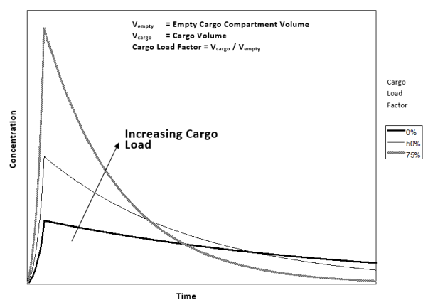
The cargo compartment should be empty for the above test. However, as shown in Figure 8-1, a compartment with cargo may be more time critical than an empty compartment for minimum fire extinguishing agent concentration levels. The time critical nature depends on several factors. Even with a pure “dump” system, having cargo does not necessarily mean a marginally performing system during an empty cargo compartment test will result in a “bad” system with cargo. Also, metering systems, if designed properly, are relatively insensitive to the cargo load factor.
Figure 8-1. Effect of Cargo Load on Halon 1301 Concentration Levels
A specific example of the effect of cargo compartment loading is shown in Figure 8-2, using the Appendix 1 simulation. If the volume of the compartment is decreased to represent increasing cargo load percentages and the leakage rate and initial Halon quantity are kept constant, then the initial Halon concentrations increase and the concentration decay rates also increase. Using this approach, the concentration in an empty compartment will decay to 3% faster than a loaded compartment up to a load percentage of about 65.6%. With compartments loaded to a higher percentage than 65.6%, the concentration will fall below 3% faster than an empty compartment.
This simulation of cargo loading assumes that the Halon concentration is homogeneous throughout the compartment and that the volume taken up by the loaded cargo is uniformly distributed throughout the compartment. Note: Both of these assumptions are not true in an actual loaded compartment so caution should be exercised to relate the measurements taken in an actual loaded compartment in flight.
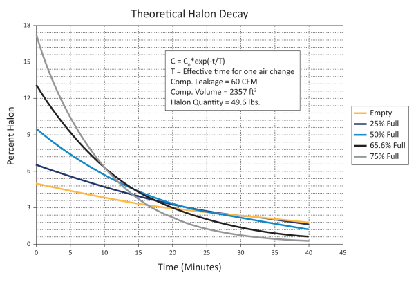
Figure 8-2
Analysis should be provided to ensure that the suppression agent concentration levels will not fall below the minimum requirement with a cargo load factor as follows:
a. For cargo compartments using only standard cargo containers, the maximum possible volume occupied by containerised cargo should be determined for the product and this value be used as the cargo load factor. This maximum volume becomes an aeroplane limitation.
b. For all other configurations, a minimum cargo load factor of 75% by volume should be used for the product.”
Appendix 1 to this AMC provides guidance on analysing Halon 1301 concentration levels.
The suppression system certification test should be conducted, as a minimum, during steady-state cruise with a maximum cabin-to-ambient pressure differential. The ventilation system should be configured per the aeroplane flight manual (AFM) procedures for a cargo compartment fire. The system should also be demonstrated acceptable for unpressurised flight conditions unless there is a restriction on unpressurised flight for the aeroplane.
It should be noted that cargo compartment leakage rates would vary between aeroplanes. This is especially significant for changes introduced by supplemental type certificate (STC) modifying aeroplanes that have been in service. Some preliminary testing should be done to determine the maximum leakage rates seen/expected in service. For new type designs the issue of wear and tear on the compartment should also be addressed when establishing the decay rate in a brand new aircraft at the factory.
9. USE OF SIMULANTS FOR CERTIFICATION TESTING
The aviation industry may continue to use Halon in cargo fire suppression applications in relation to new application for type certificate, until the end of 2018..
The EPA/EU are allowing the aviation industry to use Halon to demonstrate system functionality as long as a simulant or alternate extinguishing agent or alternate fire-extinguishing system cannot be used in place of the Halon during system or equipment testing for technical reasons. It should be noted, however, that certain states continue to ban the release of Halon for testing. The FAA Technical Center and the International Aircraft Systems Fire Protection Working Group are concentrating efforts on evaluating alternative fire-extinguishing agents and the use of simulants during certification testing. The EASA plans to approve a simulant which can be used in place of Halon 1301 during certification tests of aircraft fire-extinguishing systems to predict actual Halon 1301 volumetric concentration levels. When approved, the use of a simulant will be the preferred method for demonstrating compliance.
As of the date of this AMC, no suitable simulant for cargo compartment gaseous fire extinguishing systems has been identified. However, should the EASA be approached with the intent of utilise for the product a simulant in lieu of a Halon 1301 system or other gaseous fire extinguishing system then the recommended approach would be to perform testing which meets the Minimum Performance Standards for that application as developed by the International Aircraft Systems Fire Protection Working Group. To ensure acceptable successful means of compliance the same information as outlined above in paragraph 7 should be provided.
A simulant is defined in this AMC as a chemical agent that adequately imitates the discharge and distribution characteristics of a given extinguishing agent. It need not be an actual fire suppressant. For certain cases due to cost of the extinguishing agent, problems with supply of the extinguishing agent, etc; it may be more appropriate for the application to utilise a simulant. The Agency would require adequate analysis and testing be accomplished to establish the validity of the simulant. As a minimum, corroborating information would need to be provided as to the detailed chemical analysis of the simulant and evaluation testing of the fire extinguishing system operated with the simulant which demonstrates the equivalent behaviour. To ensure acceptable means of compliance, the following must be provided:
(1) The test data and distribution profiles using the simulant which meet the certification criteria as expressed below and in the Minimum Performance Standards as developed by FAA Technical Center as part of the International Aircraft Systems Fire Protection Working Group. (See Paragraph 15 for the listing of the references.)
(2) A system description document that includes a description of the distribution of the simulant under the test conditions in the cargo compartment.
(3) A detailed test plan.
(4) Chemical data which describes the simulant and any toxicity data.
For the application the distribution of the simulant must be described as compared with Halon 1301 under the following conditions:
a. Given the same filling conditions, the simulant is loaded into the fire extinguisher bottle based on an equivalent liquid fraction to the Halon 1301 charge weight required. This is an equivalent statement to the mass of the simulant being a specific percentage of the Halon 1301 charge weight required.
b. The fire extinguisher bottle containing the simulant is pressurised with nitrogen in an identical manner required by the Halon 1301 charge weight.
c. The simulant is discharged into the test environment, i.e. cargo compartment.
9.1 Pre-Test Considerations:
a. An EASA accepted analyser (for example, Statham-derivative analyser) capable of measuring the simulant distribution profile in the form of volumetric concentration is required.
b. An EASA accepted analyser (for example, Statham-derivative analyser) and associated hardware are configured for the particular application.
c. The fire suppression system should be completely conformed for Halon 1301.
d. The fire extinguisher bottle(s) should be serviced and prepared for the prescribed test(s).
9.2 Test Procedures:
a. Perform the prescribed distribution test in accordance with the EASA approved test plan. See Paragraph 7 for guidance on probe placement.
b. An EASA accepted analyser (for example, Statham-derivative analyser) should record the distribution profile as volumetric concentration for the simulant.
9.3 Test Result Evaluation:
a. Produce the data from the EASA accepted analyser (for example, Statham-derivative analyser) in graphical format. This format should be the volumetric concentration of the simulant versus time. A specific percent volumetric initial concentration and a specific percent volumetric metered concentration for the length of the test duration as determined by previous testing conducted per the established minimum performance standards is required for airworthiness approval of cargo compartment systems.
b. Using the Halon 1301 certification criteria, evaluate the distribution profile of the simulant for acceptable performance. The acceptability of the test data would be dependent upon the distribution profile and duration exhibited by each probe (See above and Paragraph 7 for cargo compartment fire extinguishing systems).
10. ESTABLISHING DURATION FOR THE SUPPRESSION SYSTEM.
The adequacy of the capacity of the “built-in system” is understood to mean, that there is sufficient quantity of agent to combat the fire anywhere where baggage and cargo is placed within the cargo compartment for the time duration required to land and evacuate the aeroplane. Current built-in cargo fire extinguishing systems utilise Halon 1301 as the fire extinguishing agent. Protection is afforded as long as the minimum concentration levels in the cargo compartment do not drop below three percent by volume. The time for which a suppression system will maintain the minimum required concentration levels should be identified as a certificate limitation.
The designer of the product should work with the aircraft owner and the competent authority providing operational approval to ensure that the cargo fire extinguishing system provides the required protection time (i.e., proper sizing of the cargo fire extinguishing system) for the specific route structure. The competent authority may insist on some holding time to allow for weather and other possible delays, and may specify the speeds and altitudes used to calculate aeroplane diversion times based on one‑engine‑out considerations.
The competent authority providing operational approval for the aeroplane determines the maximum allowable time, following the discovery of a fire or other emergency situation, required to divert the aeroplane to an alternate landing site. In the past, for some cases, the maximum allowable time was calculated by adding a 15 minute allowance for holding and/or approach and landing to the actual time required to reach the alternate landing site under specific operating conditions. With the issuance of this AMC, an allowance of 15 minute for approach and landing must be considered and certification data must include analysis and/or data taken after landing at a time increment which represents the completion of an evacuation of all occupants.
AMC 20-6 “Extended Range Operation with Two-Engine Aeroplanes (ETOPS),” provides acceptable means for obtaining approval under applicable operational rules for two‑engine aeroplanes operating over a route that contains a point farther than one hour’s flying time at the normal one‑engine inoperative cruise speed (in still air) from an adequate airport. It includes specific criteria for deviations of 75 minutes, 120 minutes, and 180 minutes from an adequate airport plus an allowance for 15-minute holding and/or approach and land.
Certification flight tests, supplemented by analysis for cargo load factors and additional metering system bottles as applicable, determines the maximum protection time provided by the cargo fire extinguishing system. This maximum protection time may not be the same as the maximum allowable time required to divert the aeroplane. The certificate limitation for total time, including the 15 minute allowance for holding and/or approach and landing as applicable, should never be greater than the maximum protection time provided by the cargo fire extinguishing system.
The following examples illustrate these issues:
Example 1
Maximum protection time provided
By cargo fire extinguishing system = 127 minutes
Maximum diversion time = 112 minutes + 15 minutes
(Note - in this example, the civil aviation authority required an allowance of 15 minutes for holding and/or approach and landing)
Certificate limitation for total time = 127 minutes
Example 2
Maximum protection time provided
By cargo fire extinguishing system = 68 minutes
Maximum diversion time = 60 minutes
(Note - in this example, the civil aviation authority did not require the 15 minutes allowance for holding and/or approach and landing. With the issuance of this AMC, the approach indicated in example 2 above is no longer considered an acceptable means of compliance.)
Certificate limitation for total time = 60 minutes”
11. MANUAL CONSIDERATIONS.
To ensure fire protection/fire suppression system effectiveness and safe continuation of flight and landing, the applicable aeroplane manuals should contain appropriate directives, for example:
a. Any procedures related to fighting a cargo compartment fire should be clearly defined in the Aeroplane Flight Manual (AFM).
b. Aeroplane Flight Manuals should contain instructions to land at the nearest adequate airport (or suitable airport for ETOPS ) following detection of a cargo fire.
c. Cargo loading restrictions (certified type of loading per compartment, limits for loading heights and width, etc.) should be clearly described in the Weight & Balance Manual or any other appropriate aeroplane manual.
d. Where the use of aeroplane manuals is considered to be impractical during cargo loading activities, all necessary information may be introduced into crew operating manuals or part of dedicated instructions for cargo loading personnel.
12. PLACARDS AND MARKINGS IN CARGO COMPARTMENTS
Experience has shown that under certain circumstances and despite clear instructions in the applicable aircraft documentation, cargo loading personnel may not obey loading restrictions. Especially pallets may be loaded higher than certified or bulk cargo may be stowed up to the ceiling, adversely affecting smoke detection and fire protection/fire suppression system effectiveness.
To visually indicate the applicable loading restrictions to each person being responsible for cargo loading activities in a compartment, placards and markings for certified type of cargo, maximum loading height and widths may need to be installed in that compartment.
For the design of these indications (i.e., for shape, size, colour and brightness), illumination conditions in the compartment should be considered. Markings and placards should not be easily erased, disfigured or obscured. Further guidance may be derived from compliance demonstrations for CS paragraphs regulating other internal markings and placards, for example in the cockpit or passenger compartment.
[Amdt 25/4]
[Amdt 25/12]
Appendix 1: Analytical methods for determining Halon 1301 concentration levels
ED Decision 2007/020/R
1. PURPOSE. This appendix contains analytical methods for determining Halon 1301 fire extinguishing agent concentration levels in empty or loaded cargo compartments as a function of time.
2. EXPLANATION OF TERMS AND SYMBOLS.
TABLE 2-1. TERMS AND SYMBOLS
|
SYMBOL |
DESCRIPTION |
UNITS CONSISTENT WITH EQUATIONS |
|
C(t) |
Halon 1301 concentration by volume at time “t.” = VHalon 1301 / V |
Dimensionless |
|
VHalon 1301 |
Volume of Halon 1301 in cargo compartment. |
Cubic metre - m3 (Cubic feet - ft3) |
|
V |
Cargo compartment free volume (i.e., volume not occupied by cargo). = 1 - ( Vcargo / Vempty ) |
Cubic metre - m3 (Cubic feet - ft3) |
|
Vcargo |
Cargo volume. |
Cubic metre - m3 (Cubic feet - ft3) |
|
Vempty |
Empty cargo compartment volume. |
Cubic metre - m3 (Cubic feet - ft3) |
|
T |
Time. |
Minutes – Min |
|
E |
Cargo compartment leakage rate. |
Cubic metre per minute - m3/min (Cubic feet per minute - ft3/min) |
|
S |
Specific volume of Halon 1301. |
Cubic metre per kilogram m3/kg (cubic feet per pounds(mass) ft3/lbm) |
|
R |
Halon 1301 flow rate. |
Kilogram per minute kg/min (pounds(mass) per minute lbm/min) |
3. HALON 1301 CONCENTRATION LEVEL MODEL.
Cargo compartment fire extinguishing systems generally use a combination of one or two types of Halon 1301 discharge methods. One type rapidly releases all of the fire extinguishing agent from one or more pressurised bottles into the cargo compartment. This type of discharge method is commonly known as a high rate discharge or ‘dump’ system.
FIGURE 3-1. EXAMPLE - HALON 1301 MODEL
The second type of Halon 1301 discharge method slowly releases the fire extinguishing agent from one or more pressurised bottles into the cargo compartment. This type of discharge method is commonly known as a metering system.
The following list provides some examples, not all-inclusive, of different combinations of these Halon 1301 discharge methods.
a. One high rate discharge.
b. One high rate discharge followed by a second high rate discharge at a specified later time.
c. One high rate discharge followed by a metered discharge at a specified later time.
d. Simultaneous high rate and metered discharges.
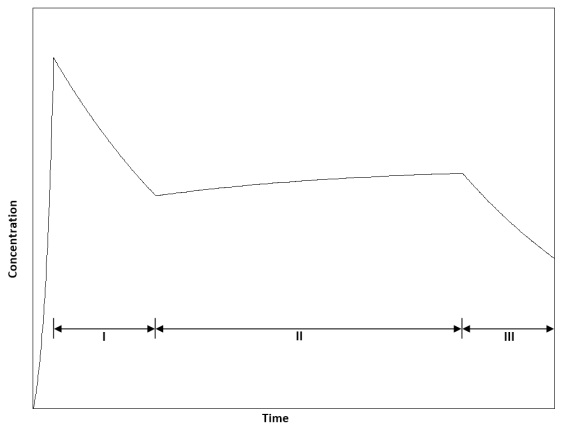
The Halon 1301 fire extinguishing system described in paragraph 3.c. above utilises both types of discharge methods and is illustrated in Figure 3-1.
Prior to Phase I - Initial High Rate Discharge of Halon 1301
This portion of the extinguishing process illustrates the high rate discharge method of releasing all of the fire extinguishing agent from one or more pressurised bottles into the cargo compartment.
Phase I - Exponential “Decay” of Halon 1301
The beginning of Phase I represents the initial concentration of Halon 1301 used to knock down a cargo fire. Since no more Halon 1301 is introduced into the cargo compartment during Phase I, the concentration of Halon 1301 undergoes an exponential “decay” versus time.
The governing equation for exponential “decay” during Phase I is the following:
C(t) = C(0) e -E t /V
NOTE - C(0) is the initial concentration of Halon 1301 used to knock down a cargo fire at the beginning of Phase I and t is the time elapsed since the beginning of Phase I.
Phase II - Metered Discharge of Halon 1301
The metered discharge of Halon 1301 starts at the beginning of Phase II. The example in Figure 3-1 shows that the metering rate is set to release Halon 1301 into the cargo compartment at a rate which is slightly greater than the rate Halon 1301 is lost through cargo compartment leakage.
The governing equation for metering during Phase II is the following:
C(t) = [ C(0) - { R S / E } ] e -E t / V + { R S / E }
NOTE - C(0) is the concentration of Halon 1301 at the end of Phase I and t is the time elapsed since the end of Phase I.
Phase III - Exponential “Decay” of Halon 1301
The beginning of Phase III marks the end of Halon 1301 metering. As in Phase I, since no more Halon 1301 is introduced into the cargo compartment, the concentration of Halon 1301 undergoes an exponential “decay” versus time.
The governing equation for exponential “decay” during Phase III is the same as during Phase I with one exception; C(0) is the concentration of Halon 1301 at the end of Phase II and t is the time since the end of Phase II.”
[Amdt 25/4]
AMC 25.851(c) Alternative fire-extinguishing agents
ED Decision 2012/008/R
1. General
The Montreal Protocol, in existence since 1987, is an international agreement to phase out production and use of ozone-depleting substances, including halogenated hydrocarbons also known as Halon. The Montreal Protocol prohibits the manufacture or import of new Halon in all developed countries as of 1 January, 1994. The US Environmental Protection Agency (EPA) has released a regulation banning the intentional release of Halons during repair, testing, and disposal of equipment containing Halons and during technician training. However, the EPA has provided the aviation industry an exemption from their ban on the intentional release of Halon in determining compliance with airworthiness standards. A European regulation7 Regulation (EC) No 2037/2000 of the European Parliament and of the Council of 29 June 2000 on substances that deplete the ozone layer. governing substances that deplete the ozone layer was also published, containing initial provisions for Halon phase-out, but also exemptions for critical uses of Halon, including fire-extinguishing in aviation. It should be noted that the exemptions were predicated on the basis that there were, at that time, no suitable alternate agents or systems available for use on commercial transport category aeroplanes.
‘Cut-off’ dates (i.e. Halon no longer acceptable in new applications for type certification) and ‘end’ dates (i.e. Halon no longer acceptable for use in aircraft) have been subsequently established by a new regulation in 20108 Commission Regulation (EU) No 744/2010 of 18 August 2010 amending Regulation (EC) No 1005/2009 of the European Parliament and of the Council on substances that deplete the ozone layer, with regard to the critical uses of halon (OJ L 218, 19.8.2010, p. 2)., as presented in Table 4.1 below:
Table 4.1: ‘Cut-off’ and ‘end’ dates
|
Aircraft compartment |
Type of extinguisher |
Type of Halon |
Dates |
|
|
Cut-off |
End |
|||
|
Inerting of fuel tanks |
Fixed |
1301 2402 |
31 December 2011 |
31 December 2040 |
|
Lavatory waste receptacles |
Built-in |
1301 1211 2402 |
31 December 2011 |
31 December 2020 |
|
Dry bays |
Fixed |
1301 1211 2402 |
31 December 2011 |
31 December 2040 |
|
Cabins and crew compartments |
Hand (portable) |
1211 2402 |
31 December 2014 |
31 December 2025 |
|
Propulsion systems and Auxiliary Power Units |
Built-in |
1301 1211 2402 |
31 December 2014 |
31 December 2040 |
|
Normally unoccupied cargo compartments |
Built-in |
1301 1211 2402 |
31 December 2018 |
31 December 2040 |
2 Lavatory extinguishing systems and agents
Historically, Halon 1301 has been the most widespread agent used in lavatory extinguishing (lavex) systems, to be used in the event of a Class A fire. Any alternative acceptable fire-extinguishing agent meeting the Minimum Performance Standards (MPS) laid down in Appendix D to Report DOT/FAA/AR-96/122 of February 1997, which includes the ability to extinguish a Class A fire and, in case of discharge, does not create an environment that exceeds the chemical agent’s ‘No Observable Adverse Effect Level’ (NOAEL) will be acceptable. Research and testing have shown that there are suitable alternatives to Halon for built-in fire extinguishers in aircraft lavatories meeting the MPS for effectiveness, volume, weight and toxicology. Currently HFC-227ea or HFC-236fa are widely used on large aeroplanes and usually considered acceptable by EASA.
3 Hand fire extinguishers and agents
Historically, Halon 1211 has been the most widespread agent in handheld (portable) fire extinguishers to be used in aircraft compartments and cabins. Minimum Performance Standards (MPS) for the agents are laid down in Appendix A to Report DOT/FAA/AR-01/37 of August 2002, while acceptable criteria to select the fire extinguishers containing said agents are laid down in the FAA Advisory Circular AC 20-42C. Version D of the same AC (published in 2011) would be preferred when the needed supporting guidance material has been released. Three agent alternatives to Halon are presently known meeting the MPS: HFC-227ea, HFC-236fa and HFC Blend B. However, these agents are significantly heavier and occupy a greater volume than Halon 1211. This may indirectly (i.e. additional weight of the fire extinguisher and additional weight of the structures supporting it) increase CO2 emissions. Furthermore, some of these agents have also been identified as having a global warming potential much higher than Halon. Therefore, further research is underway to develop additional alternatives to Halon 1211 for hand fire extinguishers.
Should an applicant wish to propose, even before the end of 2014, any alternative agent for hand fire extinguishers meeting the mentioned MPS, the EASA will initiate a Certification Review Item addressing the use of such an alternate fire-extinguishing agent.
4 Fire protection of propulsion systems and APU
Historically, Halon 1301 has been the most widespread agent used in engine nacelles and APU installations to protect against Class B fires. The MPS for agents to be used in these compartments are particularly demanding because of the presence of fuel and other volatile fluids in close proximity to high temperature surfaces, not to mention the complex air flows and the extremely low temperatures and pressures surrounding the nacelles. Various alternatives are being developed (e.g. FK-5-1-12). The FAA has issued “Minimum Performance Standards (MPS) for Halon replacement in fire-extinguishing agents/systems of civil aircraft engine and APU compartments (MPSHRe rev03)” and intends to issue rev04.
Should an applicant wish to propose, even before the end of 2014, any alternative agent for Class B fire extinction in engine or APU compartments, even in the absence of a published MPS, the EASA will initiate a Certification Review Item addressing the use of such an alternate fire-extinguishing agent.
5 Fire protection of cargo compartments — Gaseous agents
MPS for cargo compartment fire suppression systems have already been published in the Report DOT/FAA/AR-00/28 of September 2000. However, to date there are no known and sufficiently developed alternatives to Halon 1301.
Should the EASA be approached with the intent to utilise for the product an alternate agent or alternate gaseous fire-extinguishing system in lieu of a Halon 1301 system, then the recommended approach would be to perform testing on the product which meets the Minimum Performance Standards for that application as developed by the International Halon Replacement Working Group. The International Halon Replacement Working Group was established in October 1993. This group was tasked to work towards the development of minimum performance standards and test methodologies for non-Halon aircraft fire suppression agents/systems in cargo compartments, engine nacelles, handheld extinguishers, and lavatory waste receptacles. The International Halon Replacement Working Group has been expanded to include all system fire protection R&D for aircraft and now carries the name ‘International Aircraft Systems Fire Protection Working Group’.
To ensure acceptable means of compliance, the following must be provided:
a. The test data and gaseous agent distribution profiles which meet the certification criteria as expressed below and in the Minimum Performance Standards as developed by the FAA Technical Center as part of the International Halon Replacement programme. (See paragraph 7 for the listing of the references.)
b. A system description document that includes a description of the distribution of the gaseous agent under test conditions in the cargo compartment.
c. A detailed test plan.
d. Chemical data which describes the agent and any toxicity data.
5.1 Pre-test considerations:
a. An EASA accepted analyser (for example, Statham-derivative analyser) capable of measuring the agent distribution profile in the form of volumetric concentration is required.
b. An EASA accepted analyser (for example, Statham-derivative analyser) and associated hardware are configured for the particular application.
c. The fire suppression system should be completely conformed prior to the test.
d. The fire extinguisher bottle(s) should be serviced and prepared for the prescribed test(s).
5.2 Test procedures:
a. Perform the prescribed distribution test in accordance with the test plan approved by the Agency. (See Paragraph 7 in AMC 25.851(b) for guidance on probe placement.)
b. An EASA accepted analyser (for example, Statham-derivative analyser) should record the distribution profile as volumetric concentration for the agent.
5.3 Test result evaluation:
a. Produce the data from the EASA accepted analyser (for example, Statham-derivative analyser) in graphical format. This format should be the volumetric concentration of the agent versus time. A specific percentage of volumetric initial concentration and a specific percentage of volumetric metered concentration for the length of the test duration as determined by previous testing conducted per the established Minimum Performance Standards are required for airworthiness approval of cargo compartment systems.
b. Using the appropriate MPS evaluation criteria, evaluate the distribution profile of the agent for acceptable performance. The acceptability of the test data would be dependent upon the distribution profile and duration exhibited by each probe per (1) above and Paragraph 7 for cargo compartment fire-extinguishing systems.
6. EVALUATION OF ALTERNATE LIQUID AGENT AND FIRE EXTINGUISHING/SUPPRESSION SYSTEMS
The FAA Technical Center has released a Technical Note (ref. f in paragraph 7 below) that represents the latest Minimum Performance Standards (MPS) for a water spray system. However, as mentioned within the body of the report, additional developmental testing would be needed for the product and the FAA to be approached regarding certification of such a system. Additional testing would be required to demonstrate compliance with an aerosol spray. The Technical Center continues to perform research towards identifying alternate liquid and other fire-extinguishing/suppression systems. Acceptable means of compliance for these immature systems are beyond the scope of this AMC. Future revisions of this AMC will be accomplished as soon as suitable standards are developed for these systems.
If it is proposed to use a liquid fire-extinguishing agent or system for the product, the EASA should be contacted. The EASA will initiate a Certification Review Item addressing the use of an alternate fire-extinguishing agent or system.
7. REFERENCES
a. Report No FAA-RD-71-68, Fire Extinguishing Methods for New Passenger Cargo Aircraft, dated November 1971.
b. UK Civil Aviation Authority (CAA) Paper 91003, Cargo Bay Fire Suppression, dated March 1991.
c. Report No DOT/FAA/AR-96/5, Evaluation of Large Class B Cargo Compartment’s Fire Protection, dated June 1996.
d. Report No DOT/FAA/AR-96/122, Development of a Minimum Performance Standard for Lavatory Trash Receptacle Automatic Fire Extinguishers, dated February 1997.
e. Report No DOT/FAA/AR-00-28, Development of a Minimum Performance Standard for Aircraft Cargo Compartment Gaseous Fire Suppression Systems, dated September 2000.
f. Report No DOT/FAA/AR-TN01/1, Water Spray as a Fire Suppression Agent for Aircraft Cargo Compartment Fires, dated March 2001.
g. Report No DOT/FAA/AR-01/37, Development of a Minimum Performance Standard for Hand-Held Fire Extinguishers as a Replacement for Halon 1211 on Civilian Transport Category Aircraft, dated August 2002.
h. 2010 Report of the UN Halons Technical Options Committee – 2010 Assessment
i. FAA Advisory Circular AC 20-42C, Hand Fire Extinguishers for use in Aircraft, dated 07 March 1984.
j. FAA Advisory Circular AC 20-42D, Hand Fire Extinguishers for use in Aircraft, dated 14 January 2011.
[Amdt 25/12]
CS 25.853 Compartment interiors
ED Decision 2019/013/R
(See AMC 25.853)
For each compartment occupied by the crew or passengers, the following apply:
(a) Materials (including finishes or decorative surfaces applied to the materials) must meet the applicable test criteria prescribed in Part I of Appendix F or other approved equivalent methods, regardless of the passenger capacity of the aeroplane.
(b) Reserved
(c) In addition to meeting the requirements of sub-paragraph (a) of this paragraph, seat cushions, except those on flight crewmember seats, must meet the test requirements of part II of appendix F, or other equivalent methods, regardless of the passenger capacity of the aeroplane.
(d) Except as provided in sub-paragraph (e) of this paragraph, the following interior components of aeroplanes with passenger capacities of 20 or more must also meet the test requirements of parts IV and V of appendix F, or other approved equivalent method, in addition to the flammability requirements prescribed in sub-paragraph (a) of this paragraph:
(1) Interior ceiling and wall panels, other than lighting lenses and windows;
(2) Partitions, other than transparent panels needed to enhance cabin safety;
(3) Galley structure, including exposed surfaces of stowed carts and standard containers and the cavity walls that are exposed when a full complement of such carts or containers is not carried; and
(4) Large cabinets and cabin stowage compartments, other than underseat stowage compartments for stowing small items such as magazines and maps.
(e) The interiors of compartments, such as pilot compartments, galleys, lavatories, crew rest quarters, cabinets and stowage compartments, need not meet the standards of sub-paragraph (d) of this paragraph, provided the interiors of such compartments are isolated from the main passenger cabin by doors or equivalent means that would normally be closed during an emergency landing condition.
(f) Smoking is not allowed in lavatories. If smoking is allowed in any area occupied by the crew or passengers, an adequate number of self-contained, removable ashtrays must be provided in designated smoking sections for all seated occupants.
(g) Regardless of whether smoking is allowed in any other part of the aeroplane, lavatories must have self-contained removable ashtrays located conspicuously on or near the entry side of each lavatory door, except that one ashtray may serve more than one lavatory door if the ashtray can be seen readily from the cabin side of each lavatory served.
(h) Each receptacle used for the disposal of flammable waste material must be fully enclosed, constructed of at least fire resistant materials, and must contain fires likely to occur in it under normal use. The ability of the receptacle to contain those fires under all probable conditions of wear, misalignment, and ventilation expected in service must be demonstrated by test.
[Amdt No: 25/12]
[Amdt No: 25/23]
AMC 25.853 Compartment interiors
ED Decision 2020/024/R
The relevant parts of FAA Advisory Circular (AC) 25-17A Change 1, Transport Airplane Cabin Interiors Crashworthiness Handbook, dated 24.5.2016, AC 25.853-1 Flammability Requirements for Aircraft Seat Cushions, dated 17.9.1986, and AC 25-18, Transport Category Airplanes Modified for Cargo Service, dated 6.1.1994, and AC 20-178, Flammability Testing of Aircraft Cabin Interior Panels After Alterations, dated 4.6.2012, are accepted by the Agency as providing the acceptable means of compliance with CS 25.853.
Note: ‘The relevant parts’ means ‘the parts of AC 25-17A Change 1 that address the applicable FAR/CS‑25 paragraph’.
[Amdt 25/11]
[Amdt 25/17]
[Amdt 25/26]
CS 25.854 Lavatory fire protection
ED Decision 2017/015/R
(See AMC 25.854)
For aeroplanes with a passenger capacity of 20 or more, or with a cabin length of 18.29 m (60 ft) or more:
(a) Each lavatory must be equipped with a smoke detector system or equivalent that provides a warning light in the cockpit, or provides a warning light or audible warning in the passenger cabin that would be readily detected by a cabin crew member; and
(b) Each lavatory must be equipped with a built-in fire extinguisher for each disposal receptacle for towels, paper, or waste, located within the lavatory. The extinguisher must be designed to discharge automatically into each disposal receptacle upon occurrence of a fire in that receptacle.
[Amdt 25/19]
AMC 25.854 Lavatory Fire Protection
ED Decision 2017/015/R
The cabin length should be measured parallel to the aeroplane centre line from the most forward to the most aft point accessible to passengers or crew.
However, points within in-flight accessible cargo compartments, approved as meeting one of the classifications of CS 25.857, do not need to be considered.
On the flight deck, the most forward seat reference point (SRP) of the pilots’ seats (with the seats adjusted to the most forward possible positions) should be used as the most forward point.
[Amdt 25/19]
CS 25.855 Cargo or baggage compartments
ED Decision 2013/010/R
(See AMC 25.855 and 25.857)
For each cargo or baggage compartment, the following apply:
(a) The compartment must meet one of the class requirements of CS 25.857.
(b) The following cargo or baggage compartments, as defined in CS 25.857, must have a liner that is separate from, but may be attached to, the aeroplane structure:
(1) Class B through Class E cargo or baggage compartments; and
(2) Class F cargo or baggage compartments, unless other means of containing the fire and protecting critical systems and structure are provided.
(c) (1) Ceiling and sidewall liner panels of Class C cargo or baggage compartments, and ceiling and sidewall liner panels in Class F cargo or baggage compartments, if installed to meet the requirements of sub-paragraph (b)(2) of this paragraph, must meet the test requirements of Part III of Appendix F or other approved equivalent methods.
(2) Cockpit voice and flight data recorder systems, windows and systems or equipment within, or in the vicinity of, Class E cargo compartments shown to be essential for continued safe flight and landing according to CS 25.1309 must be adequately protected against fire. If protective covers are used, they must meet the requirements of Appendix F, Part III
(d) All other materials used in the construction of the cargo or baggage compartment must meet the applicable test criteria prescribed in Part I of Appendix F, or other approved equivalent methods.
(e) No compartment may contain any controls, lines, equipment, or accessories whose damage or failure would affect safe operation, unless those items are protected so that –
(1) They cannot be damaged by the movement of cargo in the compartment; and
(2) Their breakage or failure will not create a fire hazard.
(f) There must be means to prevent cargo or baggage from interfering with the functioning of the fire protective features of the compartment.
(g) Sources of heat within the compartment must be shielded and insulated to prevent igniting the cargo or baggage.
(h) Flight tests must be conducted to show compliance with the provisions of CS 25.857 concerning –
(1) Compartment accessibility;
(2) The entry of hazardous quantities of smoke or extinguishing agent into compartments occupied by the crew or passengers; and
(3) The dissipation of the extinguishing agent in Class C compartment or, if applicable, in Class F compartment.
(i) During the above tests, it must be shown that no inadvertent operation of smoke or fire detectors in any compartment would occur as a result of fire contained in any other compartment, either during or after extinguishment, unless the extinguishing system floods each such compartment simultaneously.
(j) Cargo or baggage compartment electrical wiring interconnection system components must meet the requirements of CS 25.1721.
[Amdt 25/3]
[Amdt 25/5]
[Amdt 25/8]
[Amdt 25/12]
[Amdt 25/13]
CS 25.856 Thermal/acoustic insulation materials
ED Decision 2016/010/R
(See AMC 25.856(a))
(a) Thermal/acoustic insulation material installed in the fuselage must meet the flame propagation test requirements of Part VI of Appendix F to CS-25, or other approved equivalent test requirements. This requirement does not apply to “small parts”, as defined in Part I of Appendix F to CS-25. (See AMC 25.856(a))
(b) For aeroplanes with a passenger capacity of 20 or greater, thermal/acoustic insulation materials (including the means of fastening the materials to the fuselage) installed in the lower half of the aeroplane fuselage must meet the flame penetration resistance test requirements of Part VII of Appendix F to CS-25, or other approved equivalent test requirements. This requirement does not apply to thermal/acoustic insulation installations that the Agency finds would not contribute to fire penetration resistance. (See AMC 25.856(b))
[Amdt 25/6]
[Amdt 25/18]
AMC 25.856(a) Thermal/acoustic insulation materials: Flame propagation resistance
ED Decision 2009/010/R
FAA Advisory Circular 25.856-1 Thermal/Acoustic Insulation Flame Propagation Test Method Details, dated 24/06/2005, is accepted by the Agency as providing acceptable means of compliance with CS 25.856(a) and Part VI of Appendix F to CS-25.
[Amdt 25/6]
AMC 25.856(b) Thermal/acoustic insulation materials: Flame penetration (Burnthrough) resistance
ED Decision 2009/010/R
FAA Advisory Circular 25.856-2A Installation of Thermal/Acoustic Insulation for Burnthrough Protection, dated 29/07/2008, is accepted by the Agency as providing acceptable means of compliance with CS 25.856(b) and Part VII of Appendix F to CS-25.
[Amdt 25/6]
CS 25.857 Cargo compartment classification
ED Decision 2009/017/R
(See AMC 25.855 and 25.857)
(a) Class A. A Class A cargo or baggage compartment is one in which –
(1) The presence of a fire would be easily discovered by a crew member while at his station; and
(2) Each part of the compartment is easily accessible in flight.
(b) Class B. A Class B cargo or baggage compartment is one in which –
(1) There is sufficient access in flight to enable a crewmember standing at any one access point and without stepping into the compartment, to extinguish a fire occurring in any part of the compartment using a hand fire extinguisher;
(2) When the access provisions are being used no hazardous quantity of smoke, flames or extinguishing agent will enter any compartment occupied by the crew or passengers; and
(3) There is a separate approved smoke detector or fire detector system to give warning to the pilot or flight engineer station.
(c) Class C. A Class C cargo or baggage compartment is one not meeting the requirements for either a Class A or B compartment but in which–
(1) There is a separate approved smoke detector or fire detector system to give warning at the pilot or flight engineer station;
(2) There is an approved built-in fire-extinguishing or suppression system controllable from the cockpit.
(3) There are means to exclude hazardous quantities of smoke, flames, or extinguishing agent, from any compartment occupied by the crew or passengers; and
(4) There are means to control ventilation and draughts within the compartment so that the extinguishing agent used can control any fire that may start within the compartment.
(d) Reserved.
(e) Class E. A Class E cargo compartment is one on aeroplanes used only for the carriage of cargo and in which –
(1) Reserved.
(2) There is a separate approved smoke or fire detector system to give warning at the pilot or flight engineer station;
(3) There are means to shut off the ventilating airflow to, or within, the compartment, and the controls for these means are accessible to the flight crew in the crew compartment;
(4) There are means to exclude hazardous quantities of smoke, flames, or noxious gases, from the flight-crew compartment; and
(5) The required crew emergency exits are accessible under any cargo loading condition.
(f) Class F. A Class F cargo or baggage compartment is one in which -
(1) There is a separate approved smoke detector or fire detector system to give warning at the pilot or flight engineer station;
(2) There are means to extinguish or control a fire without requiring a crewmember to enter the compartment; and
(3) There are means to exclude hazardous quantities of smoke, flames, or extinguishing agent from any compartment occupied by the crew or passengers.
[Amdt 25/3]
[Amdt 25/8]
AMC 25.855 and 25.857 Cargo or baggage compartments
ED Decision 2020/024/R
1. PURPOSE
This Acceptable Means of Compliance (AMC) sets forth an acceptable means, but not the only means, of demonstrating compliance with the provisions of the airworthiness standards for Class B and Class F cargo compartments for large aeroplanes. This AMC provides a rational method for demonstrating that the requirements of the related paragraphs of CS-25 are met and that fires occurring in the compartments can be controlled to ensure that they do not present a hazard to the aeroplane or its occupants. Like all AMC material, this AMC is not, in itself, mandatory and does not constitute a requirement. Terms used in this AMC, such as “shall” and “must,” are used only in the sense of ensuring applicability of this particular method of compliance when the acceptable method of compliance described herein is used.
2. RELATED DOCUMENTS
a. Certification Specifications.
CS 25.851 Fire extinguishers
CS 25.855 Cargo or baggage compartments
CS 25.857 Cargo compartment classification
CS 25.858 Cargo compartment fire detection systems
b. FAA Advisory Circulars (AC).
The following FAA Advisory Circulars are accepted by the Agency as providing acceptable means of compliance with CS 25.857:
AC 25-17A Change 1, Transport Airplane Cabin Interiors Crashworthiness Handbook (the relevant parts addressing the applicable FAR Part 25/CS-25 paragraphs)
AC 25-9A Smoke Detection, Penetration, and Evacuation Tests and Related Flight Manual Emergency Procedures,
AC 25-18 Transport Category Airplanes Modified for Cargo Service
AC 20-42D, Hand Fire Extinguishers for use in Aircraft
AC 25-22, Certification of Transport Airplane Mechanical Systems
FAA Order 8150.4, Certification of Cargo Containers with Self-Contained Temperature Control Systems (Active ULDs)
3. BACKGROUND
CS 25.857(b) and 25.857(f) provide standards for certification of two classes of cargo compartments, Class B and Class F.
A Class B cargo compartment is configured in a manner that allows a crewmember to extinguish or control any fire likely to occur in the compartment using a hand fire extinguisher. While the person combating the fire must have access to the compartment, it must not be necessary for that person to physically enter the compartment to extinguish the fire (see CS 25.857(b)(1)). The contents of the compartment may be reached by hand or with the contents of a hand extinguisher while standing in the entry door.
A Class F cargo compartment is similar to a Class C compartment in that there are means to extinguish or control the fire without any requirement to enter the compartment.
Both Class B and Class F cargo compartments have fire or smoke detection systems to alert the crew to the presence of the fire.
4. COMPARTMENT CLASSIFICATION
All cargo compartments must be properly classified in accordance with CS 25.857 and meet the requirements of CS 25.857 pertaining to the particular class involved (see CS 25.855 (a)).
In order to establish appropriate requirements for fire protection, a system for classification of cargo or baggage compartments was developed and adopted for large aeroplanes.
Classes A, B, and C were initially established; Classes D, E, and F were added later. Class D has been eliminated from the CS-25 specifications (by Amdt 3). The classification is based on the means by which a fire can be detected and the means available to control the fire.
a. A Class A compartment (see CS 25.857(a)) is one that is located so close to the station of a crewmember that the crewmember would discover the presence of a fire immediately. In addition, each part of the compartment is easily accessible so that the crewmember could quickly extinguish a fire with a portable fire extinguisher. A Class A compartment is not required to have a liner.
b. A Class B compartment (see CS 25.857(b)) is one that is more remote than a Class A compartment and must, therefore, incorporate a fire or smoke detection system to give warning at the pilot or flight engineer station. Because a fire would not be detected and extinguished as quickly as in a Class A compartment, a Class B compartment must have a liner in accordance with CS 25.855(b). In flight, a crewmember must have sufficient access to a Class B compartment to reach any part of the compartment by hand or with the contents of a hand extinguisher when standing at any one access point, without stepping into the compartment. There are means to ensure that, while the access provisions are being used, no hazardous quantity of smoke, flames, or extinguishing agent will enter areas occupied by the crew or passengers.
c. A Class C compartment (see CS 25.857(c)) differs from a Class B compartment in that it is not required to be accessible in flight and must, therefore, have a built-in fire extinguishing system to suppress or control any fire. A Class C compartment must have a liner and a fire or smoke detection system in accordance with CS 25.855(b) and CS 25.857(c)(1). There must also be means to exclude hazardous quantities of extinguishant and products of combustion from occupied areas (see CS 25.857(c)(3)).
d. A Class E compartment (see CS 25.857(e)) is found on an all-cargo aeroplane. Typically, a Class E compartment is the entire cabin of an all-cargo aeroplane; however, other compartments of such aeroplanes may be also classified as Class E compartments. Shutting off the ventilating airflow to or within the compartment controls a fire in a Class E compartment. A Class E compartment must have a liner (see CS 25.855(b)) and a fire or smoke detection system installed in accordance with CS 25.857(e)(2). It is not required to have a built-in fire suppression system.
e. A Class F compartment (see CS 25.857(f)) is one in which there are means to control or extinguish a fire without requiring a crewmember to enter the compartment. Allowing access by a crewmember in the presence of a fire warning is not envisioned. Class F compartments that include a built-in fire extinguisher/suppression system or require the use of acceptable fire containment covers (FCCs) would meet these requirements. The Class F compartment must have a fire or smoke detection system installed in accordance with CS 25.857(f)(1). Unless there are other means of containing the fire and protecting critical systems and structure, a Class F compartment must have a liner meeting the requirements of part III of Appendix F, or other approved equivalent methods (see CS 25.855(b)).
It is not envisaged that lower deck cargo compartments be approved as Class F cargo compartments. The Class F cargo compartment was introduced as a practicable and safe alternative to the previous practice of providing large Class B cargo compartments. These latter compartments were limited to the main deck for accessibility reasons. Lower deck cargo compartments in aircraft carrying passengers need to comply with the Class C cargo compartment requirements of CS25.857(c).
5. FIRE PROTECTION FEATURES
Based on the class of the compartment, fire protection features must be provided. The fire protection features must be shown to meet the standards established by the original type certification basis for the aeroplane or later CS-25 standards. These features may include liners, fire or smoke detection systems, hand fire extinguishers, and built-in fire suppression systems.
a. Liners
The primary purpose of a liner is to prevent a fire originating in a cargo compartment from spreading to other parts of the aeroplane before it can be brought under control. For Class B compartments, it is assumed that the fire will be quickly extinguished. Therefore, the liner does not need to be qualified to the requirements of Part III of Appendix F. For Class F cargo compartments, the fire might have grown larger prior to being suppressed, and therefore, better protection is needed to prevent damage to surrounding systems and structure. However, the liner does not need to serve as the compartment seal. It should be noted, however, that the liner is frequently used to perform the secondary functions of containing discharged extinguishing agent and controlling the flow of oxygen into the compartment. If other means, such as compartment walls, are not capable of performing those functions, the liner must be sufficiently airtight to perform them.
The liner must have sufficient fire integrity to prevent flames from burning through the liner before the fire can be brought under control and the heat from the fire is sufficiently dissipated. As stated in Part III of Appendix F, in addition to the basic liner material, the term "liner" includes any design feature, such as a joint or fastener that would affect the capability of the liner to safely contain a fire.
b. Access
(1) Class B. Class B compartments must provide sufficient accessibility to enable a crewmember to reach any part of the compartment by hand or with the contents of a hand extinguisher without physically entering the compartment. This requirement, by its nature, tends to limit the size and shape of the compartment. Additionally, the access provisions should be sufficiently large to enable the crewmember to determine visually that a fire has been extinguished. Access is also a function of how the compartment is configured rather than just dimension and/or volume. In determining access, it would not be acceptable for there to be a need to pull baggage or cargo on to the floor of the passenger compartment to gain access to the seat of the fire. Such action may introduce a safety hazard to the passengers.
"To reach any part of the compartment" means that the crewmember should be able to open the door or hatch and, standing in the opening, reach by hand anywhere in the compartment where cargo or baggage can be located. The extension of the crewmember's reach through the use of fire extinguisher wands, etc., should not be considered in determining reach.
Based on the estimated reach of a 95 percentile male, the outline of any compartment, viewed from above, should fit within a vertical cylinder of radius 132 cm (52 inches) measured from the centreline of the access door or hatch (see Figure 1). This dimension assumes the above male can reach a one foot square box located anywhere within the compartment. Access by a smaller crewmember to reach the same area within the compartment could require that the crewmember move laterally within the access door or hatch opening, while not physically entering the compartment.
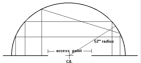
Figure 1
Example of possible cargo compartment shapes within 132 cm (52 inches) reach from access point centreline.
(2) Class F. In the case of a Class F compartment, a means should be provided to control or extinguish a fire without a crewmember entering the compartment.
One means is to design the compartment to Class C requirements but not include a built-in fire suppression system. One suppression method might be to utilize a plumbing and nozzle distribution system within the compartment that would provide acceptable suppression capability throughout the volume of the compartment. The source for such a system could be hand fire extinguishers, which interface with the distribution system through a suitable interface nozzle. This reduces the complexity and costs associated with a built-in suppression system and could be suitable for smaller compartments. For certification purposes, the extinguishing agent concentration should be measured in flight, following aeroplane flight manual (AFM) procedures, and the length of protection time afforded by the system should be recorded. This time of protection should be used to establish AFM limitations for cargo or baggage compartment fire protection times. The operator, for route planning, could then use these times. For Halon 1301 fire extinguishing agent, a minimum five percent concentration by volume at all points in the compartment is considered adequate for initial knock-down of a fire, and a three percent concentration by volume at all points in the compartment is considered the minimum for controlling a fire after it is knocked down. This option requires the use of a liner as stated in CS 25.855(b).
Another means of providing fire protection in a Class F compartment might be the use of cargo containers or fire containment covers (FCCs) shown to be capable of containing a fire. Some FCCs have already been developed and are typically constructed of woven fibreglass-based materials that will pass the oil burner test requirements of Part III of Appendix F.
This is in line with the revised CS 25.855 which for a Class F cargo or baggage compartment not using FCCs requires a ceiling and sidewall liner constructed of materials that meet the requirements of Part III of Appendix F and be separated from the aeroplane structure (except for attachments), while the floor panels must comply with Part I of Appendix F.
Similarly, if FCCs are proposed as a means of compliance for the new Class F compartment, it is likely that in order to meet the intent they must also meet these standards (i.e. Part III of Appendix F for the sides and top and Part I of Appendix F for the bottom). However, based on full scale qualification testing there is evidence that alternative materials, not fully in compliance with Part III of Appendix F, might also be acceptable for FCC side and top portions, as long as they are successfully tested and meet the intent of the rule.
It is recommended that the Agency be contacted for concurrence when FCC or Container qualification is envisaged in order to address the relevant test method.
Unless evidence can be presented to support a different design, if FCCs are used as a means of compliance, they should completely surround all cargo, including underneath the cargo, except for obviously non-flammable items, such as metal stock, machinery, and non flammable fluids without flammable packaging. Because the fire is controlled or extinguished within the isolated compartment, but is separated from the actual cargo compartment boundaries, the cargo compartment liner requirements of CS 25.855(c) would not apply. However, the effects of the heat generated by the contained/covered fire should be evaluated to ensure that adjacent systems and structure are not adversely affected. For certification purposes, test data with the actual design configuration and possible fire sources would have to be provided. The temperature and heat load time history measurements at various locations above, around and below the FCC are needed to ensure the continued safe function of adjacent systems and structure. The time history data should be used to establish the length of protection time afforded by the system and subsequent AFM limitations for cargo or baggage compartment fire protection times. The operator would then use these times for route planning purposes.
Class F cargo compartment designs which rely on fire containment, e.g. fire hardened containers/pallets and/or FCCs (placed over palletised loads or non-fire hardened containers) should be considered in regards to the possibility of incorrect usage.
All practicable means to prevent the carriage of cargo in standard containers or pallets (if special pallets are required) and/or the omission of FCCs should be incorporated. Means may include, but not be limited to, physical features at the container/pallet to cargo compartment floor interface or operational procedures such as requiring aircraft crew verification of cargo loading before every flight or a suitable detection system that would warn the crew in the event a non authorized cargo configuration has been loaded.
c. Extinguishing Agent.
In order to effectively extinguish or control a fire in a Class B or F cargo or baggage compartment, sufficient fire extinguishing agent must be allocated. Guidance on this topic is contained in FAA AC 20-42D. This guidance material is accepted by the Agency as addressing how to implement the provisions of CS 25.851(a) that require that at least one hand fire extinguisher be located in the pilot compartment, at least one readily accessible hand fire extinguisher be available for use in each Class A or Class B cargo/baggage compartment and in each accessible Class E or Class F cargo/baggage compartment, and one or more hand fire extinguishers be located in the passenger compartment for aeroplanes with a passenger seating capacity of 7 or more.
d. Fire Control.
"To control a fire" (CS 25.857(f)(2)) implies that the fire does not grow to a state where damage to the aeroplane or harm to the passengers or crew occurs during the time for which the fire protection system is demonstrated to be effective (ie, from the time a fire is detected to the time when an emergency evacuation from the aeroplane can be completed). This in turn implies that critical aeroplane systems and structure are not adversely affected and the temperature and air contaminants in areas occupied by passengers and crew do not reach hazardous levels.
(1) Adequate protection should be provided for cockpit voice and flight data recorder and wiring, windows, primary flight controls (unless it can be shown that a fire cannot cause jamming or loss of control), and other systems and equipment within the compartment that are required for safe flight and landing.
(2) Regardless of a compartment’s classification, it must be demonstrated that hazardous quantities of smoke, flames, extinguishing agent, or noxious gases do not enter any compartment occupied by passengers or crewmembers. FAA Advisory Circular 25-9A, Smoke Detection, Penetration, and Evacuation Tests and Related Flight Manual Emergency Procedures, provides guidance concerning smoke penetration testing.
(3) If an aeroplane has one or more Class B cargo compartments, portable protective breathing equipment must be provided for the appropriate crewmembers in accordance with CS 25.1439.
(4) Additional protective breathing equipment or breathing gas supply, and additional fire extinguishers, may be required for Class B cargo compartment operation to ensure that the fire can be controlled for the time the aeroplane is expected to be in the air after onset of a fire.
6. PROCEDURES AND LIMITATIONS
a. To ensure that the contents of Class B and F compartments are either accessible or located such as to allow firefighting, any cargo or baggage loading limitations and any operational limitations or procedures provided must be identified with placards in the compartment. The loading and operational limitations must also be addressed in the appropriate weight and balance or loading document.
b. Any operational limitations or procedures necessary to ensure the effectiveness of the fire protection system for Class B and Class F cargo and baggage compartments should be clearly defined in the AFM. This should include such items as any changes to the ventilation system to prevent the entrance of smoke or gases into occupied areas, use of hand fire extinguishers, use of protective breathing equipment, use of protective clothing, and use of the FCCs. The certification engineers should work closely with the Agency to ensure that additional training necessary for crewmembers assigned to combat fires is adequately addressed.
c. Any time limit for a cargo or baggage compartment fire protection system, or other conditions or procedures related to combating a fire in a compartment, should be clearly defined in the AFM.
7. AFM CONSIDERATIONS.
a. Crewmember(s) designated to combat a fire in a Class B compartment will need special training. Fires occurring in luggage are difficult to extinguish completely and rekindling may occur. Crewmembers designated to combat fires in Class B compartments should be trained to check periodically to ensure that a fire has not grown back to hazardous proportions.
b. Aeroplane flight manuals should contain instructions to land at the nearest suitable airport following smoke/fire detection, unless it can be positively determined that the fire is extinguished.
c. Any limitations regarding occupancy of Class B and Class F compartments during flight, or during takeoff and landing, should be defined in the AFM.
d. Any loading restrictions associated with access to cargo or baggage or special containers should be clearly identified in the AFM. This would include, but not be limited to, placement of luggage in a Class B compartment or identification of special containers or covers associated with fire protection in a Class F compartment. If covers are used in conjunction with a Class F cargo compartment, they should be easy to install and sufficiently durable to withstand in-service conditions.
[Amdt 25/8]
[Amdt 25/11]
[Amdt 25/12]
[Amdt 25/26]
CS 25.858 Cargo or baggage compartment smoke or fire detection systems
ED Decision 2007/010/R
If certification with cargo or baggage compartment smoke or fire detection provisions is requested, the following must be met for each cargo or baggage compartment with those provisions:
(a) The detection system must provide a visual indication to the flight crew within one minute after the start of a fire.
(b) The system must be capable of detecting a fire at a temperature significantly below that at which the structural integrity of the aeroplane is substantially decreased.
(c) There must be means to allow the crew to check in flight, the functioning of each smoke or fire detector circuit.
(d) The effectiveness of the detection system must be shown for all approved operating configurations and conditions.
[Amdt 25/3]
CS 25.859 Combustion heater fire protection
ED Decision 2003/2/RM
(a) Combustion heater fire zones. The following combustion heater fire zones must be protected from fire in accordance with the applicable provisions of CS 25.1181 to 25.1191 and 25.1195 to 25.1203:
(1) The region surrounding the heater, if this region contains any flammable fluid system components (excluding the heater fuel system) that could –
(i) Be damaged by heater malfunctioning; or
(ii) Allow flammable fluids or vapours to reach the heater in case of leakage.
(2) The region surrounding the heater, if the heater fuel system has fittings that, if they leaked, would allow fuel or vapours to enter this region.
(3) The part of the ventilating air passage that surrounds the combustion chamber. However, no fire extinguishment is required in cabin ventilating air passages.
(b) Ventilating air ducts. Each ventilating air duct passing through any fire zone must be fireproof. In addition –
(1) Unless isolation is provided by fireproof valves or by equally effective means, the ventilating air duct downstream of each heater must be fireproof for a distance great enough to ensure that any fire originating in the heater can be contained in the duct; and
(2) Each part of any ventilating duct passing through any region having a flammable fluid system must be constructed or isolated from that system so that the malfunctioning of any component of that system cannot introduce flammable fluids or vapours into the ventilating airstream.
(c) Combustion air ducts. Each combustion air duct must be fireproof for a distance great enough to prevent damage from backfiring or reverse flame propagation. In addition –
(1) No combustion air duct may have a common opening with the ventilating airstream unless flames from backfires or reverse burning cannot enter the ventilating airstream under any operating condition, including reverse flow or malfunctioning of the heater or its associated components; and
(2) No combustion air duct may restrict the prompt relief of any backfire that, if so restricted, could cause heater failure.
(d) Heater controls; general. Provision must be made to prevent the hazardous accumulation of water or ice on or in any heater control component, control system tubing, or safety control.
(e) Heater safety controls. For each combustion heater there must be the following safety control means:
(1) Means independent of the components provided for the normal continuous control of air temperature, airflow, and fuel flow must be provided, for each heater, to automatically shut off the ignition and fuel supply to that heater at a point remote from that heater when any of the following occurs:
(i) The heat exchanger temperature exceeds safe limits.
(ii) The ventilating air temperature exceeds safe limits.
(iii) The combustion airflow becomes inadequate for safe operation.
(iv) The ventilating airflow becomes inadequate for safe operation.
(2) The means of complying with sub-paragraph (e)(1) of this paragraph for any individual heater must –
(i) Be independent of components serving any other heater whose heat output is essential for safe operation; and
(ii) Keep the heater off until restarted by the crew.
(3) There must be means to warn the crew when any heater whose heat output is essential for safe operation has been shut off by the automatic means prescribed in sub-paragraph (e)(1) of this paragraph.
(f) Air intakes. Each combustion and ventilating air intake must be located so that no flammable fluids or vapours can enter the heater system under any operating condition –
(1) During normal operation; or
(2) As a result of the malfunctioning of any other component.
(g) Heater exhaust. Heater exhaust systems must meet the provisions of CS 25.1121 and 25.1123. In addition, there must be provisions in the design of the heater exhaust system to safely expel the products of combustion to prevent the occurrence of –
(1) Fuel leakage from the exhaust to surrounding compartments;
(2) Exhaust gas impingement on surrounding equipment or structure;
(3) Ignition of flammable fluids by the exhaust, if the exhaust is in a compartment containing flammable fluid lines; and
(4) Restriction by the exhaust of the prompt relief of backfires that, if so restricted, could cause heater failure.
(h) Heater fuel systems. Each heater fuel system must meet each powerplant fuel system requirement affecting safe heater operation. Each heater fuel system component within the ventilating airstream must be protected by shrouds so that no leakage from those components can enter the ventilating airstream.
(i) Drains. There must be means to safely drain fuel that might accumulate within the combustion chamber or the heater exchanger. In addition –
(1) Each part of any drain that operates at high temperatures must be protected in the same manner as heater exhausts; and
(2) Each drain must be protected from hazardous ice accumulation under any operating conditions.
CS 25.863 Flammable fluid fire protection
ED Decision 2016/010/R
(See AMC 25.863)
(a) In each area where flammable fluids or vapours might escape by leakage of a fluid system, there must be means to minimise the probability of ignition of the fluids and vapours, and the resultant hazards if ignition does occur. (See AMC 25.863(a).)
(b) Compliance with sub-paragraph (a) of this paragraph must be shown by analysis or tests, and the following factors must be considered.
(1) Possible sources and paths of fluid leakage, and means of detecting leakage.
(2) Flammability characteristics of fluids, including effects of any combustible or absorbing materials.
(3) Possible ignition sources, including electrical faults, overheating of equipment, and malfunctioning of protective devices.
(4) Means available for controlling or extinguishing a fire, such as stopping flow of fluids, shutting down equipment, fireproof containment, or use of extinguishing agents.
(5) Ability of aeroplane components that are critical to safety of flight to withstand fire and heat.
(c) If action by the flight crew is required to prevent or counteract a fluid fire (e.g. equipment shutdown or actuation of a fire extinguisher) quick acting means must be provided to alert the crew.
(d) Each area where flammable fluids or vapours might escape by leakage of a fluid system must be identified and defined.
[Amdt 25/18]
AMC 25.863(a) Flammable fluid fire protection
ED Decision 2003/2/RM
The cooling air supply for any electrical or electronic equipment should be conveyed and discharged so as not to create a hazard following failure of the equipment.
NOTE: Where necessary the cooling duct should be fireproof.
Zones with surfaces which may be exposed to flammable fluids or vapours should be ventilated if the temperature of the surfaces may exceed (under normal or failure conditions) a dangerous value with regard to these fluids or vapours. Unless a higher value can be substantiated, a temperature exceeding 200°C is considered dangerous.
CS 25.865 Fire protection of flight controls, engine mounts, and other flight structure
ED Decision 2003/2/RM
Essential flight controls, engine mounts, and other flight structures located in designated fire zones or in adjacent areas which would be subjected to the effects of fire in the fire zone must be constructed of fireproof material or shielded so that they are capable of withstanding the effects of fire.
CS 25.867 Fire protection: other components
ED Decision 2003/2/RM
(a) Surfaces to the rear of the nacelles, within one nacelle diameter of the nacelle centreline, must be constructed of materials at least equivalent in resistance to fire as aluminium alloy in dimensions appropriate for the purpose for which they are used.
(b) Sub-paragraph (a) of this paragraph does not apply to tail surfaces to the rear of the nacelles that could not be readily affected by heat, flames, or sparks coming from a designated fire zone or engine compartment of any nacelle.
CS 25.869 Fire protection: systems
ED Decision 2016/010/R
(See AMC 25.869)
(a) Electrical system components:
(1) Components of the electrical system must meet the applicable fire and smoke protection requirements of CS 25.831(c) and CS 25.863. (See AMC 25.863(a).)
(2) Equipment in designated fire zones, that is used during emergency procedures, must be at least fire resistant.
(3) Electrical Wiring Interconnection System components must meet the requirements of CS 25.1713.
(b) Each vacuum air system line and fitting on the discharge side of the pump that might contain flammable vapours or fluids must meet the requirements of CS 25.1183 if the line or fitting is in a designated fire zone. Other vacuum air systems components in designated fire zones must be at least fire resistant.
(c) (See AMC 25.869(c).) Oxygen equipment and lines must –
(1) Not be located in any designated fire zone.
(2) Be protected from heat that may be generated in, or escape from, any designated fire zone, and
(3) Be installed so that escaping oxygen cannot cause ignition of grease, fluid, or vapour accumulations that are present in normal operation or as a result of failure or malfunction of any system.
[Amdt 25/5]
[Amdt 25/18]
AMC 25.869(a)(1) Electrical System Fire and Smoke Protection
ED Decision 2003/2/RM
These requirements, and those of CS 25.863 applicable to electrical equipment, may be satisfied by the following:
1 Electrical components in regions immediately behind firewalls and in engine pod attachment structures should be of such materials and at such a distance from the firewall that they will not suffer damage that could hazard the aeroplane if the surface of the firewall adjacent to the fire is heated to 1100°C for 15 minutes.
2 Electrical equipment should be so constructed and/or installed that in the event of failure, no hazardous quantities of toxic or noxious (e.g. smoke) products will be distributed in the crew or passenger compartments.
3 Electrical equipment, which may come into contact with flammable vapours should be so designed and installed as to minimise the risk of the vapours exploding under both normal and fault conditions. This can be satisfied by meeting the Explosion Proofness Standards of RTCA DO-160/EUROCAE ED-14.
AMC 25.869(c) Fire Protection for Oxygen Equipment
ED Decision 2003/2/RM
1 High-pressure shut-off valves should be designed to provide effective slow opening and closing, so as to avoid the possible risk of fire or explosion.
2 Re-charging systems, if installed, should be provided with means to prevent excessive rates of charging which could result in dangerously high temperatures within the system. The charging system should also provide protection from contamination.
3 The compartments in which high-pressure system components, including source(s) are located should have adequate ventilation to ensure the rapid dilution of leaked oxygen. Such compartments should also provide adequate protection against contamination by liquids and other products which could result in the risk of fire.
4 Where in-situ charging facilities are provided, the compartments in which they are located should be accessible from outside the aircraft and as remote as possible from other service points and equipment. Placards should be provided, located adjacent to the servicing point, with adequate instructions covering the precautions to be observed when the system is being charged.
5 The installation of the system should be such that components and pipe lines –
a. Are adequately separated from electrical and fluid systems,
b. Are routed so as to minimise joints and sharp bends,
c. Are clear of moving controls and other mechanisms,
d. Are protected against grease or other lubricants, and are protected against the effects of vibration.
In addition, joints should where possible, be assembled dry, but where compounds are used for sealing they should be approved for that purpose.
6 Where the oxygen is supplied from chemical generators, the effects of heat emission, during both normal and inadvertent operation, on both the installation and other adjacent equipment, should be taken into account.