
CS 25.1181 Designated fire zones: regions included
ED Decision 2003/2/RM
(See AMC 25.1181.)
(a) Designated fire zones are –
(1) The engine power section;
(2) The engine accessory section;
(3) Any complete powerplant compartment in which no isolation is provided between the engine power section and the engine accessory section;
(4) Reserved.
(5) Any fuel-burning heater and other combustion equipment installation described in CS 25.859;
(6) The compressor and accessory sections of turbine engines; and
(7) Combustor, turbine, and tailpipe sections of turbine engine installations that contain lines or components carrying flammable fluids or gases.
(b) Each designated fire zone must meet the requirements of CS 25.863, 25.867, 25.869, and 25.1185 to 25.1203
AMC 25.1181 Designated fire zones
ED Decision 2003/2/RM
1 ISO 2685, (15 JULY 1992) ‘Aircraft – Environmental conditions and test procedures for airborne equipment – Resistance to fire in designated fire zones’, gives test conditions and methods of demonstrating compliance with the ‘Fire-resistant’ and ‘Fireproof’ requirements.
2 Tests to demonstrate compliance with the standard grades of resistance to fire may not be necessary if similarity can be shown with other components which have been tested in accordance with this standard.
3 For example, materials which are considered satisfactory for use in firewalls without being subjected to fire tests include –
a. Stainless steel sheet 0·4 mm (0·016 in) thick;
b. Mild steel sheet protected against corrosion 0·45 mm (0·018 in) thick; and
c. Titanium sheet 0·45 mm (0·018 in) thick.
CS 25.1182 Nacelle areas behind firewalls, and engine pod attaching structures containing flammable fluid lines
ED Decision 2003/2/RM
(a) Each nacelle area immediately behind the firewall, and each portion of any engine pod attaching structure containing flammable fluid lines, must meet each requirement of CS 25.1103(b), 25.1165(e), 25.1183, 25.1185(c), 25.1187, 25.1189 and 25.1195 to 25.1203, including those concerning designated fire zones. However, engine pod attaching structures need not contain fire detection or extinguishing means.
(b) For each area covered by sub-paragraph (a) of this paragraph that contains a retractable landing gear, compliance with that sub-paragraph need only be shown with the landing gear retracted.
CS 25.1183 Flammable fluid-carrying components
ED Decision 2003/2/RM
(a) Except as provided in sub-paragraph (b) of this paragraph, each line, fitting, and other component carrying flammable fluid in any area subject to engine fire conditions, and each component which conveys or contains flammable fluid in a designated fire zone must be fire resistant, except that flammable fluid tanks and supports in a designated fire zone must be fireproof or be enclosed by a fireproof shield unless damage by fire to any non-fireproof part will not cause leakage or spillage of flammable fluid. Components must be shielded or located to safeguard against the ignition of leaking flammable fluid.
(b) Sub-paragraph (a) of this paragraph does not apply to –
(1) Lines, fittings and components which are already approved as part of a type certificated engine; and
(2) Vent and drain lines, and their fittings, whose failure will not result in, or add to, a fire hazard.
(c) All components, including ducts, within a designated fire zone must be fireproof if, when exposed to or damaged by fire, they could –
(1) Result in fire spreading to other regions of the aeroplane, or
(2) Cause unintentional operation of, or inability to operate, essential services or equipment.
ED Decision 2003/2/RM
(a) No tank or reservoir that is a part of a system containing flammable fluids or gases may be in a designated fire zone unless the fluid contained, the design of the system, the materials used in the tank, the shut-off means, and all connections, lines and controls provide a degree of safety equal to that which would exist if the tank or reservoir were outside such a zone.
(b) There must be at least 13 mm (0·5 inches) of clear airspace between each tank or reservoir and each firewall or shroud isolating a designated fire zone.
(c) Absorbent materials close to flammable fluid system components that might leak must be covered or treated to prevent the absorption of hazardous quantities of fluids.
CS 25.1187 Drainage and ventilation of fire zones
ED Decision 2003/2/RM
(a) There must be complete drainage of each part of each designated fire zone to minimise the hazards resulting from failure or malfunctioning of any component containing flammable fluids. The drainage means must be –
(1) Effective under conditions expected to prevail when drainage is needed; and
(2) Arranged so that no discharge fluid will cause an additional fire hazard.
(b) Each designated fire zone must be ventilated to prevent the accumulation of flammable vapours.
(c) No ventilation opening may be where it would allow the entry of flammable fluids, vapours, or flame from other zones.
(d) Each ventilation means must be arranged so that no discharged vapours will cause an additional fire hazard.
(e) Unless the extinguishing agent capacity and rate of discharge are based on maximum air flow through a zone, there must be a means to allow the crew to shut-off sources of forced ventilation to any fire zone except the engine power section of the nacelle and the combustion heater ventilating air ducts.
ED Decision 2005/006/R
(See AMC 25.1189.)
(a) Each engine installation and each fire zone specified in CS 25.1181(a)(5) must have a means to shut off or otherwise prevent hazardous quantities of fuel, oil, de-icer, and other flammable fluids, from flowing into, within, or through any designated fire zone, except that shutoff means are not required for –
(1) Lines, fittings, and components forming an integral part of an engine; and
(2) Oil systems in which all components of the system in a designated fire zone, including the oil tanks, are fireproof or located in areas not subject to engine fire conditions.
(b) The closing of any fuel shut-off valve for any engine may not make fuel unavailable to the remaining engines.
(c) Operation of any shut-off means may not interfere with the later emergency operation of other equipment, such as the means for feathering the propeller.
(d) Each flammable fluid shut-off means and control must be fireproof or must be located and protected so that any fire in a fire zone will not affect its operation.
(e) No hazardous quantity of flammable fluid may drain into any designated fire zone after shut-off.
(f) There must be means to guard against inadvertent operation of the shut-off means and to make it possible for the crew to reopen the shut-off means in flight after it has been closed.
(g) Each tank-to-engine shut-off valve must be located so that the operation of the valve will not be affected by powerplant or engine mount structural failure.
(h) Each shut-off valve must have a means to relieve excessive pressure accumulation unless a means for pressure relief is otherwise provided in the system.
[Amdt 25/1]
AMC 25.1189 Flammable fluid shut-off means
ED Decision 2005/006/R
1. PURPOSE.
This Acceptable Means of Compliance (AMC) provides information and guidance concerning a means, but not the only means, of compliance with CS 25.1189 which pertains to the shut-off of flammable fluids for fire zones of Transport Category Aeroplanes. Accordingly, this material is neither mandatory nor regulatory in nature and does not constitute a regulation. In lieu of following this method, the applicant may elect to establish an alternate method of compliance that is acceptable to the Agency for complying with the requirements of the CS-25 paragraphs listed below.
2. SCOPE.
This AMC provides guidance for a means of showing compliance with regulations applicable to flammable fluid shut-off capability in Transport Category Airplanes. This guidance applies to new designs as well as modifications such as the installation of new engines or APU's or modifications of existing designs that would affect compliance to the requirements for flammable fluid shut-off means to a fire zone.
3. RELATED CERTIFICATION SPECIFICATIONS.
CS 25.863, CS 25.1181, CS 25.1182, CS 25.1189, CS 25J1189.
4. OBJECTIVE
This advisory material provides guidelines for determining hazardous quantity of flammable fluids:
A. With respect to the requirement CS 25.1189(a) that each fire zone must have a means to shut-off or otherwise prevent hazardous quantities of flammable fluids from flow into, within, or through the fire zone.
B. With respect to the requirement of CS 25.1189(e) that no hazardous quantity of flammable fluid may drain into any designated fire zone following shut-off.
5. BACKGROUND.
Guidance is required because of different and sometimes inconsistent interpretation of what hazardous quantity means.
Service History: The fire zone fire safety service history of CS-25 turbine engine aircraft has been very good, especially considering the potential hazards involved. This is attributed to the multi-faceted fire protection means required by CS-25. While it is not generally possible to define the contribution of each individual fire protection means, such as flammable fluid shut-off means, it is noted that the relatively few serious accidents that have occurred often involve initiating events such as engine separation or rotor non-containment, which can potentially negate some fire protection means, and in which flammable fluid shut-off means represent an important, or possibly sole, backup.
Previous incidents have shown that hydraulic system leaks have fuelled fires, especially when fluid mist is produced at high pressure due to small (pinhole) leaks. This type of leakage can be of considerable duration, even with a limited quantity of flammable fluid at the source.
6. DEFINITIONS.
A. Hazardous Quantity: An amount which could sustain a fire of sufficient severity and duration so as to result in a hazardous condition.
B. Hazardous Condition: Failure Conditions which would reduce the capability of the aeroplane or the ability of the crew to cope with adverse operating conditions to the extent that there would be:
(i) A large reduction in safety margins or functional capabilities;
(ii) Physical distress or higher workload such that the flight crew cannot be relied upon to perform their tasks accurately or completely; or
(iii) Serious or fatal injury to a relatively small number of the occupants;
(iv) For the purposes of this AMC, and specifically with respect to fire zone fires, any condition which could breach or exceed the fire zone integrity requirements or structural fireproofness requirements of CS-25.
C. Flammable Fluid. Flammable, with respect to a fluid or gas, means susceptible to igniting readily or to exploding. For the purpose of this AMC igniting readily includes ignition and burning when introduced into an existing flame, and includes fluids such as fuels, hydraulic fluid (including phosphate ester based fluids), oils, and deicing fluids.
7. COMPLIANCE METHODOLOGY:
The quantity of flammable fluid which is hazardous may vary with fire zone size and design, fluid characteristics, different fire scenarios, and other factors. Since one of these factors is the presence or absence of flammable fluid shut-off means, the requirements of CS 25.1189(a) and CS 25.1189(e) are discussed separately below.
7.1 Shut-off Means Requirements (CS 25.1189(a))
Compliance with CS 25.1189(a) has been typically been shown by installation of shut-off means for flammable fluids that could contribute to the hazards associated with an engine fire, except for lines fittings, and components forming an integral part of an engine and/or fireproof oil system components, which are not required to have a shut-off means per CS 25.1189(a)(1) and (a)(2). Flammable fluids that have been considered include fuel supplied to the engine/APU, fuel that may enter the fire zone from engine recirculation systems and hydraulic fluids entering the fire zone. Oil that may be supplied from outside the fire zone, deicing fluid, and other fluids would require similar consideration, however these are not typically incorporated in modern CS-25 aircraft engine installations.
Although shut-off means are typically incorporated, CS 25.1189(a) allows the option of otherwise preventing flow of hazardous quantities of flammable fluids. A shut-off means is, therefore, not required if no possible scenario will result in the flow of hazardous quantities of flammable fluid. Factors to be considered in determination of whether this compliance means is acceptable include the following:
A. Considerations
1) Leakage rates and characteristics, including massive leakage caused by component failure or fire damage, and slow leakage, which may be a spray or mist if the source is under pressure, caused by failures such as cracks or pinholes.
2) The amount of fluid in the system that is subject to leakage.
3) Combining A.1), and A.2), the range of potential duration of leakage.
4) Scenarios in which the analysed system leakage is subject to ignition and is the initial fire source.
5) Scenarios in which the initial fire source is a different system, and fire damage to the analysed system can result in leakage which contributes to the magnitude or duration of the fire.
B. Compliance
Considering the above factors and service experience of oil systems without shut-off means, it is acceptable to not install a shut-off means for specific systems which contain flammable fluid if the following conditions are met:
1) All components of the analysed system within the fire zone are fireproof, and
2) The quantity of fluid which can flow into the fire zone is not greater than the fluid quantity of the engine or APU oil system for an engine or APU fire zone, and
3) Accomplishment of AFM Emergency Procedures will preclude continuation of a pressurized spray or mist.
The meeting of conditions (1)-(3) are considered acceptable in precluding a hazardous quantity of flammable fluids from flowing into, within or through any designated fire zone.
7.2 Drainage Following Shut-off Requirements (CS 25.1189(e))
Following shut-off, flammable fluid will be contained within the components and plumbing in the fire zone, and usually within plumbing between the firewall and shut-off means. This is due to other requirements which affect the location of the shut-off means and, therefore, the amount of fluid between the shut-off means and the firewall that may drain into the fire zone following shut-off. These include the requirement to protect the shut-off means from a fire zone fire (CS 25.1189(d)), a powerplant or engine mount structural failure (CS 25.1189(g)), and engine rotor failure (CS 25.903(d)(1)).
An analysis is required for each individual flammable fluid system to determine that the total amount is not hazardous. The analysis should consider the aircraft attitudes expected to be encountered during continued flight following shut-off, which may include emergency descent attitudes, but would not be expected to include climb attitudes steeper than those associated with one engine inoperative flight at V2. If the analysed system traverses more than one fire zone, each fire zone should be analysed separately for the maximum fluid volume which can drain into that fire zone. Credit should not be taken for fire extinguishing provisions. The following are alternate criteria for hazardous quantities of flammable fluid for this condition:
A) A volume not exceeding 0·95 litre (1 US quarts) is not hazardous, or
B) An amount shown not to be hazardous by analysis considering the factors listed in 7.1.A above.
Additional factors relevant to this condition following shut-off are reduction in pressurized spray or mist due to reduction or absence of system pressure, and the possibility of rapid leakage or drainage due to either an initial leak or fire damage of plumbing and components, such as aluminium components or non-metallic hoses, following the required fire resistance period. Hazard assessment of such rapid leakage and drainage may include airflow ventilation limitation of fire intensity, and fire duration limitation through fire zone drainage.
The analysis may consider that volume which is capable of being drained from the nacelle within a suitable period is not hazardous. The suitable period should be such that fluid leakage into the fire zone will not aggravate a fire beyond a fifteen minute period from its initiation. A five minute period may be suitable when considering fire resistant components and plumbing for which leakage due to fire damage will not occur during the first five minute period and may not occur immediately thereafter.
[Amdt 25/1]
ED Decision 2003/2/RM
(a) Each engine, fuel-burning heater, other combustion equipment intended for operation in flight, and the combustion, turbine, and tailpipe sections of turbine engines, must be isolated from the rest of the aeroplane by firewalls, shrouds, or equivalent means.
(b) Each firewall and shroud must be –
(1) Fireproof;
(2) Constructed so that no hazardous quantity of air, fluid, or flame can pass from the compartment to other parts of the aeroplane;
(3) Constructed so that each opening is sealed with close fitting fireproof grommets, bushings, or firewall fittings; and
(4) Protected against corrosion.
CS 25.1193 Cowling and nacelle skin
ED Decision 2018/005/R
(a) Each cowling must be constructed and supported so that it can resist any vibration, inertia, and air load to which it may be subjected in operation.
(b) Cowling must meet the drainage and ventilation requirements of CS 25.1187.
(c) On aeroplanes with a diaphragm isolating the engine power section from the engine accessory section, each part of the accessory section cowling subject to flame in case of fire in the engine power section of the powerplant must –
(1) Be fireproof; and
(2) Meet the requirements of CS 25.1191.
(d) Each part of the cowling subject to high temperatures due to its nearness to exhaust system parts or exhaust gas impingement must be fireproof.
(e) Each aeroplane must:
(1) Be designed and constructed so that no fire originating in any fire zone can enter, either through openings or by burning through external skin, any other zone or region where it would create additional hazards;
(2) Meet sub-paragraph (e)(1) of this paragraph with the landing gear retracted (if applicable); and
(3) have cowlings and nacelles skins, in areas subject to flame if a fire starts in an engine fire zone, complying with the following:
(i) For in-flight operations, cowlings and nacelles skins must be fireproof in the complete concerned areas, and
(ii) For ground operations, cowlings and nacelles skins must be:
(a) Fireproof in the portions of the concerned areas where a skin burn through would affect critical areas of the aeroplane, and
(b) Fire-resistant or compliant with subparagraph (e)(1) of this paragraph in the remaining portions of the concerned areas.
(4) Be designed and constructed to minimise the likelihood of any in-flight opening or loss of a cowling that could prevent continued safe flight and landing.
(f) The retention system of each removable or openable cowling must:
(1) keep the cowling closed and secured under the operational loads identified in subparagraph (a) of this paragraph following either of the following conditions:
(i) improper fastening of any single latching, locking, or other retention device, or
(ii) the failure of any single latch or hinge.
(2) have readily accessible means to close and secure the cowling that do not require excessive force or manual dexterity; and
(3) have a reliable means for effectively verifying that the cowling is secured prior to each take-off.
(See AMC 25.1193(e))
[Amdt 25/13]
[Amdt 25/18]
[Amdt 25/21]
AMC 25.1193(e) Engine cowling and nacelle skin, APU compartment external skin
ED Decision 2013/010/R
(a) PURPOSE
This AMC provides guidance for showing compliance with the certification specifications relating to fire withstanding capability of engine cowlings and nacelles skins, and APU compartment external skins, in areas subject to flame if a fire starts in an engine or APU fire zone, in consideration of potential hazard levels associated to operating conditions (flight/ground).
(b) RELATED CERTIFICATION SPECIFICATIONS
(c) APPLICABILITY
This AMC is applicable to engine cowlings and nacelles, and APU compartment external skins (fixed and/or removable).
(d) BACKGROUND
CS 25.1193(e) and CS 25J1193(e) previously required the engine cowlings/nacelle skins and APU compartment external skins to be fireproof if a fire starts in the engine power or accessory sections or in the APU compartment. During past Type certification projects, it has been found that having non-fireproof engine cowlings/nacelle skins in some locations under some operating conditions do not adversely affect safety. Consequently, in practice, not all cowlings/skins ‘subject to flame if a fire starts in the engine power or accessory sections’ have been required to be fireproof under all operating conditions and, for instance, some portions were approved as fire-resistant only for ground operating conditions. As it represented a rule relaxation, such non-fireproof cowlings/skins were formally found to be ‘equivalently safe’ to comply with the rule. Over time, however, these equivalent safety findings became inherent within traditionally accepted design practices. Certification Review Item (CRI) released to cover the relaxation included also interpretations for zone definitions and operating conditions to be considered for fireproofness or fire-resistance compliance demonstration.
(e) FIRE WITHSTANDING REQUIREMENTS, OPERATING CONDITIONS AND POTENTIAL HAZARDS
(1) General
The required level of ability to withstand the effects of fire varies with the potential hazard level associated with different flight and ground operating conditions, as follows.
(2) Flight Conditions
For the purpose of CS 25.1193(e) and CS 25J1193(e), flight conditions are defined as aeroplane operation from airspeed above minimum V1 until minimum touchdown speed in approved normal or abnormal operations. Cowling and skin in areas subject to flame if a fire starts in an engine or APU fire zone must be demonstrated to be fireproof.
For demonstrating the fireproof capabilities of the cowling/skin, the following apply:
(i) Credit from the external airflow on the cowling/skin can be considered.
(ii) The airflow levels and the engine/APU powers should be consistent with the operating conditions. These parameters should be examined and the most critical ones should be determined.
(iii) The engine/APU should be considered to be operative for the first 5 minutes, and during the remaining 10 minutes under windmilling conditions for engine and stopped conditions for the APU.
(3) Ground conditions
For the purpose of CS 25.1193(e) and CS 25J1193(e), ground conditions are defined as aircraft operation not covered by the flight conditions provided in subparagraph (e)(2) of this AMC. It includes static, taxiing, take-off roll, and landing roll.
(i) Areas where fireproof skins are required — The portion of cowling and skin in areas subject to flames if a fire starts in an engine or APU fire zone, and located so that not containing the effects of the fire could result in serious hazards to the aircraft, injuries to crew, passengers or ground personnel, must be fireproof under all conditions. Serious hazards include, but are not limited to, events such as fuel tank explosion, hazardous spread of fire to flammable fluid sources outside the fire zone, fuselage penetration and flight control surface damages.
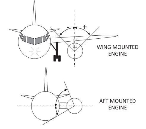
(A) Pod-mounted engines: The portion of the nacelle/cowling skin, which is required to be fireproof on ground, varies by installation. A design is considered acceptable when it is demonstrated that the fireproof area protects the pylon strut and other portions of the aircraft considered to be put at a serious hazard risk if a burn through occurs. Factors to consider within the analysis and to use when substantiating the design are: the engine location — wing or aft fuselage mounted, the coupling distance of the nacelle to the wing, the airflow characteristics, the fluid migration scheme and the fire plume patterns. After the initial analysis, similarity demonstration and in-service experience may be used as appropriate. Analyses have demonstrated that the typical area of concern ranges from 90° (± 45°) to 180° (± 90°) and is centred on the pylon centre line. This area may increase or decrease depending on the analysis results. For example, most wing mounted engines not closely coupled to the wing have been found acceptable with a ± 45° protection while more closely coupled installations and those with other unique design features have required ± 90° protection. The symmetry of the protection may also vary. Wing mounted engines usually have symmetrical protection while aft mounted engines may have non-symmetrical protection in order to cover more of the inboard area.
(B) Turbo-propellers, APUs and other non-pod-mounted engines: Due to the wide variations in installation configurations, each installation should be evaluated to determine if not containing the effects of a fire would cause a serious hazard such as the examples above. If so, the affected area of the fire zone skin should be fireproof.
(C) For the purpose of the demonstration:
— No credit from external airflow on the cowling/skin should be considered in conjunction with the assumption that the aircraft may be static.
— The engine/APU should be considered to be operative for the first 5 minutes and stopped for the remaining 10 minutes.
— Engine/APU operation — Requirements for ability of cowling/skin in areas subject to flames if a fire starts in an engine or APU fire zone to withstand the effects of fire in ground operating conditions apply with either the engine operating or not operating, whichever is the more critical. The Engine/APU operating conditions shall be justified by the applicant.
(ii) Other areas: For the remaining portions of cowling/skin in areas subject to flames, if a fire starts in an engine or APU fire zone, the degree of fire resistance can be lower than ‘fireproof’ due to less serious or less probable hazard to the aircraft, crew, passengers and ground personnel under the critical operating conditions. Any burn through of the APU compartment external skin should consider hazards associated with combustion product and possible outgassing and re-ingestion of toxic air into cabin air system.
(A) Fire-resistant cowlings/skins provide adequate fire protection for those areas as they provide sufficient time to stop the aeroplane and evacuate it.
(B) A lower than ‘fire-resistant’ degree of fire protection may be considered; the following conditions should then be analysed and submitted to the Agency for approval:
— Cowling/skin should have the ability to withstand fire at least equivalent to the ability of a 1 mm (0.040 inch) aluminium sheet in the worst aircraft and engine/APU ground conditions anticipated;
— Applicants must substantiate that this lower fire protection level will not lead to hazardous effects including but not limited to:
— Upon burn through of the lower than ‘fire-resistant’ area, both the fire-resistant and/or fire-proof areas shall not have their fire withstanding capability affected,
— Liberation of parts that would affect the aeroplane evacuation procedure or reduce the efficiency of fire protection means,
— Reduction in flammable fluid drainage capability such that fire severity would be increased (magnitude, residual presence, propagation to surrounding area),
— Reduction in aeroplane evacuation capability due to proximity to evacuation paths or due to the visibility of the fire hindering the ability of the passengers to evacuate the aeroplane in a rapid and orderly manner,
Note: There is some hazard involving aeroplane evacuation even in the absence of burn through due to such concerns as smoke and flaming liquids exiting from openings. Burn through of nacelle skin should not significantly increase these hazards.
— Reduction in fire detection capability such that the flight crew would not be aware of the fire, especially in a situation involving taxiing prior to take-off,
— Reduction in fire extinguishing capability which could cause or aggravate one of the potential hazards listed above.
— Flammable fluid and/or fire spreading on the aeroplane evacuation path
(f) SPECIFIC CONFIGURATION CONSIDERATIONS
(1) Multiple skin layers: For some specific fire zones, a fire originating in that zone will have to pass through several layers of cowling or skin before burning through the external skin. This may be the case, for example, for the core zone of some turbofan installations. In such cases, credit may be taken for multiple layers, having regard to the location of the fire source and the likely direction of propagation from that location, providing burn through of the inner layer does not produce other hazardous effects and it does not invalidate other certification specifications such as fire extinguishing capability. The corresponding compliance substantiation should take into account particular geometrical configuration with respect to the risk of flame propagation, as well as critical systems or structures.
(2) Inlet skins: For external inlet skins, which enclose fire zones, the guidance provided above for multiple skin layers applies. Inlet ducts should meet CS 25.1103/CS 25J1103 specifications.
(3) Openings: The following considerations are applicable to openings in a fire zone skin whether the openings are of fixed size, variable or controllable size, or normally closed, such as access or inspection doors, or pressure relief doors.
(i) Openings should be located such that flame exiting the opening would not enter any other region where it could cause a hazard in flight or a serious hazard on the ground as per subparagraph (e)(3). Exception is made for covered openings which meet the same criteria for ability to withstand the effects of fire as the surrounding cowl skin, and which are not expected to become open under fire conditions. Since pressure relief doors may open during some fire conditions, they should be located such that flames exiting the door will not cause a hazard. However, doors that will remain closed during most fire conditions, or will tend to re-close following initial opening, have traditionally been assumed to be closed for the purposes of evaluating fire detection and extinguishing.
(ii) Openings should have the same ability to withstand the effects of fire as the adjacent skin with respect to becoming enlarged under fire conditions. Some enlargement, such as burning away of louvers or doublers surrounding the opening or gapping of covered openings, is acceptable provided that the hazard is not significantly increased by a reduction in fire extinguishing or detection capability, increased airflow causing increase in fire size or intensity, or increase in probability of a hazardous spread of fire to other regions.
(4) Hinges, Fittings and Latches: These attaching means maintaining the nacelle/cowlings between them or to the aircraft/engine/APU structure may need to have a greater ability to withstand the effect of fire than the surrounding skin. Loss of attaching means may create more severe hazards such as cowling liberation in comparison to a skin burn through. The applicant must justify the required level of fire withstanding capability by test and/or analysis.
(5) Seals: Where seals are used part of the external engine nacelle/cowling or APU compartment boundaries, they should at least comply with the same fire integrity standard as the surrounding cowling/skin.
(g) COMPLIANCE DEMONSTRATION
Compliance should be substantiated per CS 25.1207. Substantiation involving airflow patterns may include analytical methods such as Computational Fluid Dynamics, test methods or other flow visualisation methods or a combination of these methods. Fire testing should be accomplished according to the guidance of ISO 2685 with considerations of applications of representative conditions (airflow, loads, vibrations) and establishment of appropriate pass/fail criteria (burn through, elongation, dislocation).
[Amdt 25/13]
AMC 25.1193(e)(4) and (f) Engine cowling retention
ED Decision 2018/005/R
a. Purpose and scope
CS 25.1193(e)(4) requires design precautions to be taken to minimise the risk of any in-flight opening or loss of an engine cowling that could prevent continued safe flight and landing. CS 25.1193(f) requires the retention system of each removable or openable cowling to have a means, which is demonstrated to be reliable and effective, to verify that the cowling is closed and latched prior to each take-off.
Reported occurrences of engine cowling separations revealed that features like latch handles hanging down, cowling gaps, and detection capabilities offered by walk-arounds and/or checks at the completion stage of maintenance activities, had not been reliable or effective in preventing aeroplanes from taking off with unclosed/unlatched cowlings.
For turbofan engines, these occurrences have concerned fan cowls only. Thrust reverser cowls have shown satisfactory in-service experience with regard to the risk of a cowling separation. Therefore, specifications CS 25.1193(e)(4) and (f) are intended to be applicable to engine fan cowls only.
All dispatch configurations, as permitted by the master minimum equipment list (MMEL) and the configuration deviation list (CDL), should be considered when showing compliance with CS 25.1193(e)(4) and (f).
b. Selection of appropriate design features
The following guidelines are provided to help the applicant in selecting design features appropriate to the engine/nacelle characteristics, and in showing compliance with CS 25.1193(e)(4) and (f).
Human factors
In determining the most appropriate design feature, or combination of design features, to cope with the human-factor aspects that contribute to the risk of an aeroplane being released with unclosed or unlatched cowlings, attention should be placed on the following aspects of cowling latched/unlatched indications:
— Their verification by personnel should not necessitate unusual physical effort (e.g. bending down or kneeling on the ground);
— Their verification by personnel should take into account the variability in the physical capabilities of personnel;
— The provision of these indications should take into account a possible lack of diligence of personnel in conducting walk‑arounds and in completing their maintenance activities;
— The combination of indications should draw the attention of personnel without ambiguity (e.g. by paint effects) and should not be rendered ineffective by lighting conditions (night/day), weather conditions, or the operational environment.
Design considerations
The following considerations should be taken into account when selecting design features to mitigate the risk of a cowling separation:
— A wing-mounted engine/nacelle presents a higher risk than a rear-mounted engine/nacelle, therefore it requires more noticeable cowling latched/unlatched indications and/or a combination of them;
— An engine/nacelle with a small ground clearance presents a higher risk than one with a large ground clearance, therefore it requires more noticeable indications and/or a combination of them;
— A hanging heavy/large piece or part on an engine/nacelle with a large ground clearance may draw the attention of personnel;
— A unique indication on the lower part of an engine/nacelle that has a small ground clearance may not be sufficient to draw attention to it;
— The noticeability of a forced gap between the fan cowl and the surrounding structure may be adversely affected by its environment, such as the ambient lighting conditions, external painting or the condition of the surrounding structure, and may not be individually sufficient to draw attention to it;
— A flashing light in an open gap or outside the nacelle skin may draw the attention of personnel. In such cases, the reliability of the flashing light should be investigated and substantiated, taking into account the effects of the engine/nacelle environment;
— A mechanical flag on the outside of the nacelle skin may draw the attention of personnel;
— A latch which is locked by a key equipped with a red flag may draw the attention of personnel, however a duplicate key without a flag could be used, and therefore the use of a flag may not be sufficient;
— A design with a remote indication (i.e. on the flight deck) of the unlatched/unclosed fan cowl condition may effectively draw the attention of the flight crew.
Other guidelines
Furthermore, the following guidelines related to the use of some of the design features should be taken into account by the applicant:
— Procedural control measures may not always be followed as a result of the pressure to dispatch the aeroplane, and because of routine issues;
— Improper Instructions for Continuing Airworthiness may be issued, which may lead to:
— Improper rigging of the cowls and the associated latches;
— Poor maintenance of design features intended to prevent aeroplane dispatch with unlatched cowlings, such as bright paint fading over time (or becoming soaked with the dirt accumulated at the bottom of the nacelle), hold-open cowl devices not performing their intended function, etc.;
— Some nacelle painting can defeat the design precautions:
— Red or orange nacelle colours may negate the visibility of red/dayglow latches;
— A dark nacelle colour may reduce the noticeability of gaps.
— Specific tools may be improperly defined and maintained (e.g. keys required to open cowls, normally fitted with a red flag, being used without a flag).
In order to address the human factors that contribute to the risk, it might be necessary to conduct an in‑service and practical evaluation of the proposed design.
[Amdt 25/21]
CS 25.1195 Fire-extinguisher systems
ED Decision 2016/010/R
(See AMC 25.1195)
(a) Except for combustor, turbine, and tail pipe sections of turbine engine installations that contain lines or components carrying flammable fluids or gases for which it is shown that a fire originating in these sections can be controlled, there must be a fire extinguisher system serving each designated fire zone.
(b) The fire-extinguishing system, the quantity of the extinguishing agent, the rate of discharge, and the discharge distribution must be adequate to extinguish fires. It must be shown by either actual or simulated flight tests that under critical airflow conditions in flight the discharge of the extinguishing agent in each designated fire zone specified in sub-paragraph (a) of this paragraph will provide an agent concentration capable of extinguishing fires in that zone and of minimising the probability of re-ignition. An individual ‘one-shot’ system may be used for fuel burning heaters, and other combustion equipment. For each other designated fire zone, two discharges must be provided each of which produces adequate agent concentration. (See AMC 25.1195(b).)
(c) The fire-extinguishing system for a nacelle must be able to simultaneously protect each zone of the nacelle for which protection is provided.
[Amdt 25/18]
AMC 25.1195(b) Fire extinguisher systems
ED Decision 2012/008/R
Acceptable methods to establish the adequacy of the fire extinguisher system are laid down in Advisory Circular 20-100. with reference to Halon concentration levels. This AC is not applicable to extinguishing agents alternative to Halon.
[Amdt 25/12]
CS 25.1197 Fire-extinguishing agents
ED Decision 2012/008/R
(See AMC 25.1197.)
(a) Fire-extinguishing agents must –
(1) Be capable of extinguishing flames emanating from any burning of fluids or other combustible materials in the area protected by the fire extinguishing system; and
(2) Have thermal stability over the temperature range likely to be experienced in the compartment in which they are stored.
(b) If any toxic extinguishing agent is used, provisions must be made to prevent harmful concentrations of fluid or fluid vapours (from leakage during normal operation of the aeroplane or as a result of discharging the fire extinguisher on the ground or in flight) from entering any personnel compartment, even though a defect may exist in the extinguishing system. This must be shown by test except for built-in carbon dioxide fuselage compartment fire extinguishing systems for which –
(1) 2.3 kg (five pounds) or less of carbon dioxide will be discharged, under established fire control procedures, into any fuselage compartment; or
(2) There is protective breathing equipment for each flight-crew member on flight deck duty.
[Amdt 25/12]
AMC 25.1197 Fire-Extinguishing Agents
ED Decision 2012/008/R
Halon 1301 is no longer an acceptable extinguishing agent, based on EU Law9 Commission Regulation (EU) No 744/2010 of 18 August 2010 amending Regulation (EC) No 1005/2009 of the European Parliament and of the Council on substances that deplete the ozone layer, with regard to the critical uses of halon (OJ L 218, 19.8.2010, p. 2)., for engine nacelle and APU fire extinction systems to be installed in aircraft types, for which type certification is requested after 31 December 2014. (See AMC 25.851(c) for more information on Halon alternatives.)
[Amdt 25/12]
CS 25.1199 Extinguishing agent containers
ED Decision 2003/2/RM
(a) Each extinguishing agent container must have a pressure relief to prevent bursting of the container by excessive internal pressures.
(b) The discharge end of each discharge line from a pressure relief connection must be located so that discharge of the fire extinguishing agent would not damage the aeroplane. The line must also be located or protected to prevent clogging caused by ice or other foreign matter.
(c) There must be a means for each fire extinguishing agent container to indicate that the container has discharged or that the charging pressure is below the established minimum necessary for proper functioning.
(d) The temperature of each container must be maintained, under intended operating conditions, to prevent the pressure in the container from –
(1) Falling below that necessary to provide an adequate rate of discharge; or
(2) Rising high enough to cause premature discharge.
(e) If a pyrotechnic capsule is used to discharge the extinguishing agent, each container must be installed so that temperature conditions will not cause hazardous deterioration of the pyrotechnic capsule.
CS 25.1201 Fire extinguishing system materials
ED Decision 2003/2/RM
(a) No material in any fire extinguishing system may react chemically with any extinguishing agent so as to create a hazard.
(b) Each system component in an engine compartment must be fireproof.
CS 25.1203 Fire-detector system
ED Decision 2008/006/R
(a) There must be approved, quick acting fire or overheat detectors in each designated fire zone, and in the combustion, turbine, and tailpipe sections of turbine engine installations, in numbers and locations ensuring prompt detection of fire in those zones.
(b) Each fire detector system must be constructed and installed so that –
(1) It will withstand the vibration, inertia, and other loads to which it may be subjected in operation;
(2) There is a means to warn the crew in the event that the sensor or associated wiring within a designated fire zone is severed at one point, unless the system continues to function as a satisfactory detection system after the severing; and
(3) There is a means to warn the crew in the event of a short circuit in the sensor or associated wiring within a designated fire zone, unless the system continues to function as a satisfactory detection system after the short circuit.
(c) No fire or overheat detector may be affected by any oil, water, other fluids, or fumes that might be present.
(d) There must be means to allow the crew to check, in flight, the functioning of each fire or overheat detector electric circuit.
(e) Components of each fire or overheat detector system in a fire zone must be at least fire-resistant.
(f) No fire or overheat detector system component for any fire zone may pass through another fire zone, unless –
(1) It is protected against the possibility of false warnings resulting from fires in zones through which it passes; or
(2) Each zone involved is simultaneously protected by the same detector and extinguishing system.
(g) Each fire detector system must be constructed so that when it is in the configuration for installation it will not exceed the alarm activation time approved for the detectors using the response time criteria specified in the appropriate European Technical Standard Order for the detector.
(h) Electrical wiring interconnection systems for each fire or overheat detector system in a fire zone must meet the requirements of CS 25.1713 and 1731.
[Amdt 25/5]
ED Decision 2003/2/RM
Unless otherwise specified, compliance with the requirements of CS 25.1181 to 25.1203 must be shown by a full scale fire test or by one or more of the following methods:
(a) Tests of similar powerplant configurations;
(b) Tests of components;
(c) Service experience of aeroplanes with similar powerplant configurations;
(d) Analysis.