
ED Decision 2014/026/R
(a) If certification with ditching provisions is requested, the aeroplane must meet the requirements of this paragraph and CS 25.807(i), 25.1411 and 25.1415(a).
(b) Each practicable design measure, compatible with the general characteristics of the aeroplane, must be taken to minimise the probability that in an emergency landing on water, the behaviour of the aeroplane would cause immediate injury to the occupants or would make it impossible for them to escape.
(c) The probable behaviour of the aeroplane in a water landing must be investigated by model tests or by comparison with aeroplanes of similar configuration for which the ditching characteristics are known. Scoops, wing-flaps, projections, and any other factor likely to affect the hydrodynamic characteristics of the aeroplane, must be considered.
(d) It must be shown that, under reasonably probable water conditions, the flotation time and trim of the aeroplane will allow the occupants to leave the aeroplane and enter the life rafts required by CS 25.1415. If compliance with this provision is shown by buoyancy and trim computations, appropriate allowances must be made for probable structural damage and leakage. If the aeroplane has fuel tanks (with fuel jettisoning provisions) that can reasonably be expected to withstand a ditching without leakage, the jettisonable volume of fuel may be considered as buoyancy volume.
(e) Unless the effects of the collapse of external doors and windows are accounted for in the investigation of the probable behaviour of the aeroplane in a water landing (as prescribed in sub-paragraphs (c) and (d) of this paragraph), the external doors and windows must be designed to withstand the probable maximum local pressures.
[Amdt 25/15]
ED Decision 2021/015/R
EASA accepts the relevant parts of Federal Aviation Administration (FAA) AC 25-17A ‘Transport Airplane Cabin Interiors Crashworthiness Handbook’, of 24 May 2016, as an acceptable means of compliance with CS 25.801(d).
Note: ‘relevant parts’ means the AC 25-17A parts that address the applicable Federal Aviation Regulation (FAR)/CS-25 paragraph(s).
[Amdt No: 25/27]
CS 25.803 Emergency evacuation
ED Decision 2003/2/RM
(See AMC 25.803)
(a) Each crew and passenger area must have emergency means to allow rapid evacuation in crash landings, with the landing gear extended as well as with the landing gear retracted, considering the possibility of the aeroplane being on fire.
(b) Reserved.
(c) For aeroplanes having a seating capacity of more than 44 passengers, it must be shown that the maximum seating capacity, including the number of crew members required by the operating rules for which certification is requested, can be evacuated from the aeroplane to the ground under simulated emergency conditions within 90 seconds. Compliance with this requirement must be shown by actual demonstration using the test criteria outlined in Appendix J of this CS-25 unless the Agency find that a combination of analysis and testing will provide data equivalent to that which would be obtained by actual demonstration.
AMC 25.803 Emergency evacuation
ED Decision 2020/024/R
The relevant parts of FAA Advisory Circular (AC) 25-17A Change 1, Transport Airplane Cabin Interiors Crashworthiness Handbook, dated 24.5.2016 and AC 25.803-1A Emergency Evacuation Demonstrations, dated 3.12.2012 are accepted by the Agency as providing acceptable means of compliance with CS 25.803.
Note: ‘The relevant parts’ means ‘the parts of AC 25-17A Change 1 that address the applicable FAR/CS‑25 paragraph’.
[Amdt 25/11]
[Amdt 25/12]
[Amdt 25/26]
ED Decision 2020/024/R
(See AMC 25.807)
(a) Type. For the purpose of this CS-25, the types of exits are defined as follows:
(1) Type I. This type is a floor level exit with a rectangular opening of not less than 61 cm (24 inches) wide by 121.9 cm (48 inches) high, with corner radii not greater than 20.3 cm (8 inches).
(2) Type II. This type is a rectangular opening of not less than 50.8 cm (20 inches) wide by 111.8 cm (44 inches) high, with corner radii not greater than 17.8 cm (7 inches). Type II exits must be floor-level exits unless located over the wing, in which case they must not have a step-up inside the aeroplane of more than 25.4 cm (10 inches) nor a step-down outside the aeroplane of more than 43.2 cm (17 inches).
(3) Type III. This type is a rectangular opening of not less than 50.8 cm (20 inches) wide by 91.4 cm (36 inches) high, with corner radii not greater than 17.8 cm (7 inches), and with a step-up inside the aeroplane of not more than 50.8 cm (20 inches). If the exit is located over the wing, the step-down outside the aeroplane may not exceed 68.6 cm (27 inches).
(4) Type IV. This type is a rectangular opening of not less than 48.3 cm (19 inches) wide by 66.0 cm (26 inches) high, with corner radii not greater than 16.0 cm (6.3 inches), located over the wing, with a step-up inside the aeroplane of not more than 73.7 cm (29 inches) and a step-down outside the aeroplane of not more than 91.4 cm (36 inches).
(5) Ventral. This type is an exit from the passenger compartment through the pressure shell and the bottom fuselage skin. The dimensions and physical configuration of this type of exit must allow at least the same rate of egress as a Type I exit with the aeroplane in the normal ground attitude, with landing gear extended.
(6) Tail cone. This type is an aft exit from the passenger compartment through the pressure shell and through an openable cone of the fuselage aft of the pressure shell. The means of opening the tail cone must be simple and obvious and must employ a single operation.
(7) Type A. This type is a floor-level exit with a rectangular opening of not less than 106.7 cm (42 inches) wide by 182.9 cm (72 inches) high, with corner radii not greater than 17.8 cm (7 inches).
(8) Type B. This type is a floor-level exit with a rectangular opening of not less than 81.3 cm (32 inches) wide by 182.9 cm (72 inches) high, with corner radii not greater than 15.3 cm (6 inches).
(9) Type C. This type is a floor-level exit with a rectangular opening of not less than 76.2 cm (30 inches) wide by 121.9 cm (48 inches) high, with corner radii not greater than 25.4 cm (10 inches).
(b) Step down distance. Step down distance, as used in this paragraph, means the actual distance between the bottom of the required opening and a usable foot hold, extending out from the fuselage, that is large enough to be effective without searching by sight or feel.
(c) Over-sized exits. Openings larger than those specified in this paragraph, whether or not of rectangular shape, may be used if the specified rectangular opening can be inscribed within the opening and the base of the inscribed rectangular opening meets the specified step-up and step-down heights.
(d) Asymmetry. Exits of an exit pair need not be diametrically opposite each other nor of the same size; however, the number of passenger seats permitted under subparagraph (g) of this paragraph is based on the smaller of the two exits.
(e) Uniformity. Exits must be distributed as uniformly as practical, taking into account passenger seat distribution. (See AMC 25.807(e))
(f) Location. (See AMC 25.807(f))
(1) Each required passenger emergency exit must be accessible to the passengers and located where it will afford the most effective means of passenger evacuation.
(2) If only one floor-level exit per side is prescribed, and the aeroplane does not have a tail cone or ventral emergency exit, the floor-level exits must be in the rearward part of the passenger compartment unless another location affords a more effective means of passenger evacuation.
(3) If more than one floor-level exit per side is prescribed, and the aeroplane does not have a combination cargo and passenger configuration, at least one floor-level exit must be located on each side near each end of the cabin.
(4) For an aeroplane that is required to have more than one passenger emergency exits for each side of the fuselage, no passenger emergency exit shall be more than 18.3 m (60 feet) from any adjacent passenger emergency exit on the same side of the same deck of the fuselage, as measured parallel to the aeroplane’s longitudinal axis between the nearest edges.
(g) Type and number required. The maximum number of passenger seats permitted depends on the type and number of exits installed on each side of the fuselage. Except as further restricted in subparagraphs (g)(1) through (g)(9) of this paragraph, the maximum number of passenger seats permitted for each exit of a specific type installed on each side of the fuselage is as follows:
|
Type A |
110 |
|
Type B |
75 |
|
Type C |
55 |
|
Type I |
45 |
|
Type II |
40 |
|
Type III |
35 |
|
Type IV |
9 |
(1) For a passenger seating configuration of 1 to 9 seats, there must be at least one Type IV or larger over-wing exit on each side of the fuselage or, if over-wing exits are not provided, at least one exit on each side that meets the minimum dimensions of a Type III exit.
(2) For a passenger seating configuration of more than 9 seats, each exit must be a Type III or larger exit.
(3) For a passenger seating configuration of 10 to 19 seats, there must be at least one Type III or larger exit on each side of the fuselage.
(4) For a passenger seating configuration of 20 to 40 seats, there must be at least two exits, one of which must be a Type II or larger exit, on each side of the fuselage.
(5) For a passenger seating configuration of 41 to 110 seats, there must be at least two exits, one of which must be a Type I or larger exit, on each side of the fuselage.
(6) For a passenger seating configuration of more than 110 seats, the emergency exits on each side of the fuselage must include at least two Type I or larger exits.
(7) The combined maximum number of passenger seats permitted for all Type III exits is 70, and the combined maximum number of passenger seats permitted for two Type III exits on each side of the fuselage that are separated by fewer than three passenger seat rows is 65.
(8) If a Type A, Type B, or Type C exit is installed, there must be at least two Type C or larger exits on each side of the fuselage.
(9) If a passenger ventral or tail cone exit is installed and that exit provides at least the same rate of egress as a Type III exit with the aeroplane in the most adverse exit opening condition that would result from the collapse of one or more legs of the landing gear, an increase in the passenger seating configuration is permitted as follows:
(i) For a ventral exit, 12 additional passenger seats.
(ii) For a tail cone exit incorporating a floor-level opening of not less than 50.8 cm (20 inches) wide by 152.4 cm (60 inches) high, with corner radii not greater than 17.8 cm (7 inches), in the pressure shell and incorporating an approved assisting means in accordance with CS 25.810(a), 25 additional passenger seats.
(iii) For a tail cone exit incorporating an opening in the pressure shell which is at least equivalent to a Type III emergency exit with respect to dimensions, step-up and step-down distance, and with the top of the opening not less than 142.2 cm (56 inches) from the passenger compartment floor, 15 additional passenger seats.
(h) Other exits. The following exits must also meet the applicable emergency exit requirements of CS 25.809 through 25.812, and must be readily accessible:
(1) Each emergency exit in the passenger compartment in excess of the minimum number of required emergency exits.
(2) Any other floor-level door or exit that is accessible from the passenger compartment and is as large or larger than a Type II exit, but less than 116.8 cm (46 inches) wide.
(3) Any other ventral or tail cone passenger exit.
(i) Ditching emergency exits for passengers. Whether or not ditching certification is requested, ditching emergency exits must be provided in accordance with the following conditions, unless the emergency exits required by subparagraph (g) of this paragraph already meet them:
(1) For aeroplanes that have a passenger seating configuration of nine seats or less, excluding pilot seats, one exit above the waterline in each side of the aeroplane, meeting at least the dimensions of a Type IV exit.
(2) For aeroplanes that have a passenger seating configuration of 10 seats or more, excluding pilot seats, one exit above the waterline in a side of the aeroplane, meeting at least the dimensions of a Type III exit for each unit (or part of a unit) of 35 passenger seats, but no less than two such exits in the passenger cabin, with one on each side of the aeroplane. The passenger seat/exit ratio may be increased through the use of larger exits, or other means, provided it is shown that the evacuation capability during ditching has been improved accordingly.
(3) If it is impractical to locate side exits above the waterline, the side exits must be replaced by an equal number of readily accessible overhead hatches of not less than the dimensions of a Type III exit, except that for aeroplanes with a passenger configuration of 35 seats or less, excluding pilot seats, the two required Type III side exits need to be replaced by only one overhead hatch.
(j) Flight crew emergency exits. For aeroplanes in which the proximity of passenger emergency exits to the flight crew area does not offer a convenient and readily accessible means of evacuation of the flight crew, and for all aeroplanes having a passenger seating capacity greater than 20, flight crew exits must be located in the flight crew area. Such exits must be of sufficient size and so located as to permit rapid evacuation by the crew. One exit must be provided on each side of the aeroplane; or, alternatively, a top hatch must be provided. Each exit must encompass an unobstructed rectangular opening of at least 48.3 cm by 50.8 cm (19 by 20 inches) unless satisfactory exit utility can be demonstrated by a typical crew member.
[Amdt 25/4]
[Amdt 25/5]
[Amdt 25/6]
[Amdt 25/12]
[Amdt 25/18]
[Amdt 25/19]
[Amdt 25/26]
ED Decision 2020/024/R
The term ‘unobstructed’ should be interpreted as referring to the space between the adjacent wall(s) and/or seat(s), the seatback(s) being in the most adverse position, in vertical projection from floor -level to at least the prescribed minimum height of the exit.
The relevant parts of FAA Advisory Circular (AC) 25-17A Change 1, Transport Airplane Cabin Interiors Crashworthiness Handbook, dated 24.5.2016 are accepted by the Agency as providing acceptable means of compliance with CS 25.807.
Note: ‘The relevant parts’ means ‘the parts of the AC 25-17A Change 1 that address the applicable FAR/CS-25 paragraph’.
[Amdt 25/12]
[Amdt 25/19]
[Amdt 25/26]
AMC 25.807(f) Passenger emergency exits
ED Decision 2012/008/R
The optimum fore and aft location of Types I, II and III exits should be agreed between the applicant and the Agency bearing in mind the relevant considerations, including –
a. The varying likelihood of damage to different parts of the fuselage in emergency landing conditions, and
b. The need to avoid the passengers having to evacuate the aeroplane where dangerous conditions (spilt fuel, hot engine parts, etc.) may exist.
[Amdt 25/11]
[Amdt 25/12]
AMC 25.807(e) Emergency Exits Uniformity
ED Decision 2017/015/R
FAA Advisory Circular 25.807-1 ‘Uniform Distribution of Exits’, dated 08/13/90 is accepted by EASA as providing acceptable means of compliance with CS 25.807(e).
However, this Advisory Circular does not provide any guidance for those aeroplanes required to have no more than one pair of emergency exits. For those aeroplanes, ensuring that the seat-to-exit distance remains within acceptable limits as per the following criteria provides an acceptable means of compliance with CS 25.807(e).
Each passenger seat approved for use during taxiing, take-off or landing should be located such that:
(i) it is within 9.14 m (30 ft) from the nearest emergency exit on one side of the fuselage, and within 13.72 m (45 ft) from the nearest emergency exit on the other side of the fuselage; and
(ii) the occupant of that seat has the possibility to move to an emergency exit, on the left side, or the right side of the fuselage, whilst at all points along the way remaining within 9.14 m (30 ft) from an emergency exit on one side of the fuselage and within 13.72 m (45 ft) from an emergency exit on the other side of the fuselage.
When calculating the distance from a passenger seat, or from any point in the egress path of an occupant, to an emergency exit, this distance should be taken as the total longitudinal distance (i.e. as measured parallel to the aeroplane’s longitudinal axis) that the escapee should cover in order to get to the emergency exit in question (i.e. the distance calculated should take into account all required changes in direction of movement but measured only longitudinally). For the distance from a passenger seat, as the starting point, the front edge of the seat bottom cushion at the centreline, with the seat in the taxiing, take off, and landing position is to be taken for seats installed at any orientation. The end point in each case is to be taken as the nearest edge of the emergency exit opening in the fuselage.
For aeroplanes with a passenger seating configuration of 19 or less, only one pair of emergency exits is required. However, such aeroplanes may have additional exits installed, which must then comply with CS 25.807(h) but not with the 18.3-m (60-feet) rule of CS 25.807(f)(4). The distance between each passenger seat and the nearest available emergency exit may be determined considering all available emergency exits, including the ones addressed by CS 25.807(h).
[Amdt 25/19]
CS 25.809 Emergency exit arrangement
ED Decision 2015/019/R
(See AMC 25.809)
(a) (1) Each emergency exit, including a flight crew emergency exit, must be a movable door or hatch in the external walls of the fuselage, allowing unobstructed opening to the outside.
(2) Each emergency exit, including a flight crew emergency exit, must have means to permit viewing of the conditions outside the exit when the exit is closed, in all ambient lighting conditions with the landing gears extended or in any condition of collapse. The viewing means may be on or adjacent to the exit provided no obstructions exist between the exit and the viewing means. (See AMC 25.809(a))
(3) For non-over-wing passenger emergency exits, a means must also be provided to permit viewing of the likely areas of evacuee ground contact when the exit is closed with the landing gears extended or in any condition of collapse. Furthermore, the likely areas of evacuee ground contact must be viewable with the exit closed during all ambient lighting conditions when all landing gears are extended.
(b) Each emergency exit must be openable from the inside and the outside except that sliding window emergency exits in the flight crew area need not be openable from the outside if other approved exits are convenient and readily accessible to the flight crew area. Inward opening doors may be used if there are means to prevent occupants from crowding against the door to an extent that would interfere with the opening of the door. Each emergency exit must be capable of being opened, when there is no fuselage deformation –
(1) With the aeroplane in the normal ground attitude and in each of the attitudes corresponding to collapse of one or more legs of the landing gear; and
(2) Within 10 seconds measured from the time when the opening means is actuated to the time when the exit is fully opened.
(3) Even though persons may be crowded against the door on the inside of the aeroplane.
(c) The means of opening emergency exits must be simple and obvious and may not require exceptional effort; and must be arranged and marked so that it can be readily located and operated, even in darkness. Internal exit opening means involving sequence operations (such as operation of two handles or latches or the release of safety catches) may be used for flight crew emergency exits if it can be reasonably established that these means are simple and obvious to crewmembers trained in their use.
(d) If a single power-boost or single power-operated system is the primary system for operating more than one exit in an emergency, each exit must be capable of meeting the requirements of sub-paragraph (b) of this paragraph in the event of failure of the primary system. Manual operation of the exit (after failure of the primary system) is acceptable.
(e) Each emergency exit must be shown by tests, or by a combination of analysis and tests, to meet the requirements of sub-paragraphs (b) and (c) of this paragraph.
(f) Each door must be located where persons using them will not be endangered by the propellers when appropriate operating procedures are used.
(g) There must be provisions to minimise the probability of jamming of the emergency exits resulting from fuselage deformation in a minor crash landing.
(h) [Reserved]
(i) Each emergency exit must have a means to retain the exit in the open position, once the exit is opened in an emergency. The means must not require separate action to engage when the exit is opened, and must require positive action to disengage.
[Amdt 25/4]
[Amdt 25/12]
[Amdt 25/14]
[Amdt 25/17]
AMC 25.809 Emergency exit arrangement
ED Decision 2020/024/R
The relevant parts of FAA Advisory Circular (AC) 25-17A Change 1, Transport Airplane Cabin Interiors Crashworthiness Handbook, dated 24.5.2016, are accepted by the Agency as providing an acceptable means of compliance with CS 25.809.
Note: ‘The relevant parts’ means ‘the parts of AC 25-17A Change 1 that address the applicable FAR/CS‑25 paragraph’.
[Amdt 25/12]
[Amdt 25/17]
[Amdt 25/26]
AMC 25.809(a) Emergency exit outside viewing
ED Decision 2015/019/R
The requirement to provide a view of the outside in all ambient lighting conditions suggests the use of externally mounted lighting (although other means may be acceptable). In the landing-gear-collapsed cases, the rolling and pitching effects on the fuselage may redirect a fixed lamp’s beam away from the area illuminated in the all-landing-gears-extended condition. Furthermore, in the case of inflatable escape slides, the toe-end ground contact point will probably move in the opposite direction to that of the lamp beam.
In recognition of these effects, and in order to maintain reasonable demands on the complexity and power of external lighting equipment, the rule does not require the entire viewable area to be visible in all ambient lighting conditions. The only specific illumination requirement is for the likely areas of evacuee ground contact, with all landing gears extended, for passenger exits.
However, it is recommended that as large a field of view as is practicable should be provided, taking into account aspects such as fuselage curvature and door/window/hatch location, in order to provide the best chance to identify external evacuation hazards before exits are opened.
In the case of a flight crew emergency exit, a flight deck window as conventionally configured, used in conjunction with a suitably accessible and powerful portable illumination device (e.g. flashlight) will provide an acceptable means for viewing the outside conditions.
Flight deck seats, consoles, etc., as conventionally configured, are not considered to be obstructions in the meaning of this term in CS 25.809(a)(2) in the case where flight deck windows are the viewing means and the exit is an overhead hatch. Furthermore, it is considered that the distance between flight deck windows, as conventionally configured, and an overhead hatch is such that the criterion for the viewing means to be adjacent to the exit is satisfied.
[Amdt 25/17]
AMC 25.809(a)(3) Emergency exit arrangement
ED Decision 2012/008/R
A subjective outside viewing test can be conducted to determine if the exterior viewing means and lighting system provide an adequate view/illumination to allow identification of possible hazards in the evacuee ground contact area. For this test, the viewing/lighting system will be deemed acceptable if an object (e.g., a traffic cone) placed in the viewing area is visible to the test witness looking through the emergency exit viewing means that is provided.
When a separate lighting system is installed that is only used to meet the requirements of CS 25.809(a), that system should be designed to meet the requirements of CS 25.812(k), for operation after having been subjected to the inertia forces listed in CS 25.561(b), and CS 25.812(l)(3), such that at least one exterior light on each side of the airplane remains operative after a single transverse separation.
[Amdt 25/12]
AMC 25.809(c) and (e) Testing of the opening of passenger‑operated exits
ED Decision 2020/024/R
For emergency exits intended to be operated by passengers, such as non-floor-level overwing exits (e.g. Type III and IV exits), testing with naïve subjects should be performed in order to demonstrate that opening the emergency exits is simple and obvious and does not require exceptional effort.
The demonstration may be conducted either on the aeroplane or on a representative mock-up, and it should include all the relevant safety markings and exit opening instructions.
The opening of the emergency exit should be demonstrated by a sufficient number of naïve test subjects selected to be representative of the passenger population with respect to gender, age, size and handedness. Meeting the criteria of paragraph (h) of Appendix J to CS-25 is an acceptable means to achieve a representative age and gender distribution of the participants in the test.
CS 25.810 Emergency egress assisting means and escape routes
ED Decision 2016/010/R
(See AMC 25.810)
(a) Each non-over-wing Type A, Type B or Type C exit, and any other non-over-wing landplane emergency exit more than 1.8 m (6 feet) from the ground with the aeroplane on the ground and the landing gear extended must have an approved means to assist the occupants in descending to the ground.
(1) The assisting means for each passenger emergency exit must be a selfsupporting slide or equivalent; and, in the case of a Type A or Type B exits, it must be capable of carrying simultaneously two parallel lines of evacuees. In addition, the assisting means must be designed to meet the following requirements.
(i) It must be automatically deployed and deployment must begin during the interval between the time the exit opening means is actuated from inside the aeroplane and the time the exit is fully opened. However, each passenger emergency exit which is also a passenger entrance door or a service door must be provided with means to prevent deployment of the assisting means when it is opened from either the inside or the outside under non-emergency conditions for normal use.
(ii) Except for assisting means installed at Type C exits, it must be automatically erected within 6 seconds after deployment is begun or within 10 seconds from the time the opening means of the exit is actuated. Assisting means installed at Type C exits must be automatically erected within 10 seconds from the time the opening means of the exit is actuated.
(iii) It must be of such length after full deployment that the lower end is selfsupporting on the ground and provides safe evacuation of occupants to the ground after collapse of one or more legs of the landing gear.
(iv) It must have the capability, in 46 km/hr (25-knot) winds directed from the most critical angle, simultaneously with any engine(s) running at ground idle, to deploy and, with the assistance of only one person, to remain usable after full deployment to evacuate occupants safely to the ground. (See AMC 25.810(a)(1)(iv))
(v) For each system installation (mock-up or aeroplane installed), five consecutive deployment and inflation tests must be conducted (per exit) without failure, and at least three tests of each such five-test series must be conducted using a single representative sample of the device. The sample devices must be deployed and inflated by the system’s primary means after being subjected to the inertia forces specified in CS 25.561(b). If any part of the system fails or does not function properly during the required tests, the cause of the failure or malfunction must be corrected by positive means and after that, the full series of five consecutive deployment and inflation tests must be conducted without failure.
(2) The assisting means for flight crew emergency exits may be a rope or any other means demonstrated to be suitable for the purpose. If the assisting means is a rope, or an approved device equivalent to a rope, it must be–
(i) Attached to the fuselage structure at or above the top of the emergency exit opening, or, for a device at a pilot’s emergency exit window, at another approved location if the stowed device, or its attachment, would reduce the pilot’s view in flight.
(ii) Able (with its attachment) to withstand a 1779 N (400-lbf) static load.
(b) Assisting means from the cabin to the wing are required for each Type A or Type B exit located above the wing and having a step-down unless the exit without an assisting means can be shown to have a rate of passenger egress at least equal to that of the same type of non-over-wing exit. If an assisting means is required, it must be automatically deployed and automatically erected, concurrent with the opening of the exit. In the case of assisting means installed at Type C exits, it must be self-supporting within 10 seconds from the time the opening means of the exits is actuated. For all other exit types, it must be self-supporting 6 seconds after deployment has begun.
(c) An escape route must be established from each over-wing emergency exit, and (except for flap surfaces suitable as slides) covered with a slip resistant surface (See AMC to CS 25.793 and CS 25.810(c)). Except where a means for channelling the flow of evacuees is provided –
(1) The escape route from each Type A or Type B emergency exit, or any common escape route from two Type III emergency exits, must be at least 1·07 m (42 inches) wide; that from any other passenger emergency exit must be at least 61 cm (24 inches) wide; and
(2) The escape route surface must have a reflectance of at least 80%, and must be defined by markings with a surface-to-marking contrast ratio of at least 5:1. (See AMC 25.810(c)(2))
(d) Assisting means must be provided to enable evacuees to reach the ground for all Type C exits located over the wing and, if the place on the aeroplane structure at which the escape route required in subparagraph (c) of this paragraph terminates, is more than 1.8 m (6 feet) from the ground with the aeroplane on the ground and the landing gear extended, for all other exit types.
(1) If the escape route is over a flap, the height of the terminal edge must be measured with the flap in the take-off or landing position, whichever is higher from the ground.
(2) The assisting means must be usable and self-supporting with one or more landing gear legs collapsed and under a 46 km/hr (25-knot) wind directed from the most critical angle.
(3) The assisting means provided for each escape route leading from a Type A or B emergency exit must be capable of carrying simultaneously two parallel lines of evacuees; and, the assisting means leading from any other exit type must be capable of carrying simultaneously as many parallel lines of evacuees as there are required escape routes.
(4) The assisting means provided for each escape route leading from a Type C exit must be automatically erected within 10 seconds from the time the opening means of the exit is actuated, and that provided for the escape route leading from any other exit type must be automatically erected within 10 seconds after actuation of the erection system.
(e) If an integral stair is installed in a passenger entry door that is qualified as a passenger emergency exit, the stair must be designed so that, under the following conditions, the effectiveness of passenger emergency egress will not be impaired:
(1) The door, integral stair, and operating mechanism have been subjected to the inertia forces specified in CS 25.561(b)(3), acting separately relative to the surrounding structure.
(2) The aeroplane is in the normal ground attitude and in each of the attitudes corresponding to collapse of one or more legs of the landing gear.
[Amdt 25/4]
[Amdt 25/12]
[Amdt 25/13]
[Amdt 25/17]
[Amdt 25/18]
AMC 25.810 Emergency egress assisting means and escape routes
ED Decision 2020/024/R
The relevant parts of FAA Advisory Circular (AC) 25-17A Change 1, Transport Airplane Cabin Interiors Crashworthiness Handbook, dated 24.5.2016, are accepted by the Agency as providing an acceptable means of compliance with CS 25.810.
Note: ‘The relevant parts’ means ‘the parts of AC 25 -17A Change 1 that address the applicable FAR/CS‑25 paragraph’.
[Amdt 25/17]
[Amdt 25/26]
AMC 25.810(a)(1)(iv) Capability of assisting means in wind conditions
ED Decision 2016/010/R
The applicability of the combined effect of a 46 km/hr (25-knot) wind and the engine(s) running at ground idle should be only to escape slides positioned forward of the engine(s) and in such proximity to the engine air intake(s) that the deployment of the escape slide could be influenced.
[Amdt 25/18]
AMC 25.810(a)(1)(v) Deployment and inflation tests
ED Decision 2020/024/R
For each exit, at least one of the (minimum) five consecutive deployment and inflation tests should be performed with an assisting means installed on the aeroplane.
CS 25.811 Emergency exit marking
ED Decision 2017/015/R
(See AMC 25.811)
(a) Each passenger emergency exit, its means of access, and its means of opening must be conspicuously marked.
(b) The identity and location of each passenger emergency exit must be recognisable from a distance equal to the width of the cabin.
(c) Means must be provided to assist the occupants in locating the exits in conditions of dense smoke.
(d) The location of each passenger emergency exit must be indicated by a sign visible to occupants approaching along the main passenger aisle (or aisles). There must be See AMC 25.811(d)):
(1) A passenger emergency exit locator sign above the aisle (or aisles) near each passenger emergency exit, or at another overhead location if it is more practical because of low headroom, except that one sign may serve more than one exit if each exit can be seen readily from the sign;
(2) A passenger emergency exit marking sign next to each passenger emergency exit, except that one sign may serve two such exits if they both can be seen readily from the sign; and
(3) A sign on each bulkhead or divider that prevents fore and aft vision along the passenger cabin to indicate emergency exits beyond and obscured by the bulkhead or divider, except that if this is not possible the sign may be placed at another appropriate location.
(e) The location of the operating handle and instructions for opening exits from the inside of the aeroplane must be shown in the following manner:
(1) Each passenger emergency exit must have, on or near the exit, a marking that is readable from a distance of 76 cm (30 inches).
(2) Each passenger emergency exit operating handle and the cover removal instructions, if the operating handle is covered, must –
(i) Be self-illuminated with an initial brightness of at least 0.51 candela/m2 (160 microlamberts), or
(ii) Be conspicuously located and well illuminated by the emergency lighting even in conditions of occupant crowding at the exit.
(3) Reserved
(4) All Type II and larger passenger emergency exits with a locking mechanism released by motion of a handle, must be marked so as to its operation by an arrow with a shaft at least 19 mm (0.75 inches) wide, adjacent to the handle, that indicates the full extent and direction of the unlocking motion required. The word OPEN must be horizontally situated adjacent to the arrowhead and must be in red capital letters at least 25 mm (1 inch) high. The arrow and word OPEN must be located on a background, which provides adequate contrast. (See AMC 25.811(e)(4).)
(f) Each emergency exit that is required to be openable from the outside, and its means of opening, must be marked on the outside of the aeroplane. In addition, the following apply:
(1) The outside marking for each passenger emergency exit in the side of the fuselage must include a 51 mm (2 inch) coloured band outlining the exit.
(2) Each outside marking including the band must have colour contrast to be readily distinguishable from the surrounding fuselage surface. The contrast must be such that if the reflectance of the darker colour is 15% or less, the reflectance of the lighter colour must be at least 45%. ‘Reflectance’ is the ratio of the luminous flux reflected by a body to the luminous flux it receives. When the reflectance of the darker colour is greater than 15%, at least a 30% difference between its reflectance and the reflectance of the lighter colour must be provided.
(3) In the case of exits other than those in the side of the fuselage, such as ventral or tail cone exits, the external means of opening, including instructions if applicable, must be conspicuously marked in red, or bright chrome yellow if the background colour is such that red is inconspicuous. When the opening means is located on only one side of the fuselage, a conspicuous marking to that effect must be provided on the other side.
(g) Each sign required by sub-paragraph (d) of this paragraph may use the word ‘exit’ in its legend in place of the term ‘emergency exit’ or a universal symbolic exit sign (See AMC 25.812(b)(1), AMC 25.812(b)(2) and AMC 25.812(e)(2)). The design of exit signs must be chosen to provide a consistent set throughout the cabin.
[Amdt 25/3]
[Amdt 25/17]
[Amdt 25/19]
AMC 25.811 Emergency exit marking
ED Decision 2020/024/R
The relevant parts of FAA Advisory Circular (AC) AC 25-17A Change 1, Transport Airplane Cabin Interiors Crashworthiness Handbook, dated 24.5.2016, are accepted by the Agency as providing an acceptable means of compliance with CS 25.811.
Note: ‘The relevant parts’ means ‘the parts of AC25-17A Change 1 that address the applicable FAR/CS‑25 paragraph’.
[Amdt 25/17]
[Amdt 25/26]
AMC 25.811(d) Sign Combination
ED Decision 2020/024/R
The signs required by CS 25.811(d)(1), (d)(2) and (d)(3) may be combined according to the applicable parts of FAA Advisory Circular (AC) 25-17A Change 1, Transport Airplane Cabin Interiors Crashworthiness Handbook, dated 24.5.2016.
[Amdt 25/19]
[Amdt 25/26]
AMC 25.811(e)(4) Emergency exit marking
ED Decision 2017/015/R
The indicating markings for all Type II and larger passenger emergency exit unlocking handle motions should conform to the general shapes and dimensions indicated by Figures 1 and 2.
The indicating markings (arrow and word OPEN) should be consistent with the emergency exit signs chosen, i.e. red if letter emergency exit signs are installed, and green if symbolic emergency exit signs are installed.
NOTE: As far as is practicable the markings should be located to avoid obscuring viewing windows located on or alongside the exits, or coincidence with any other required marking or safety feature.
EXAMPLE MARKING FOR INDICATION OF LINEAR OPENING MOTION
Where practical and unambiguous arrow point and base of arrow shaft to be within ±25 mm (1 inch) of fully unlocked and fully locked positions respectively
DIMENSIONS
A = 19 mm (0·75") minimum
B = 2 x A
C = B (recommended)
D = Indicative of the full extent of handle travel (each installation to be individually assessed)
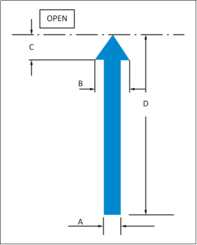
FIGURE 1
EXAMPLE MARKING FOR INDICATION OF ROTARY OPENING MOTION
Arrow point and base of arrow shaft to be within 25 mm (1 inch) of fully unlocked and fully locked positions respectively
DIMENSIONS
A = 19 mm (0·75") minimum
B = 2 x A
C = B (recommended)
D = Full extent of handle centreline travel
E = Three quarters of handle length (where practicable)
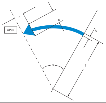
FIGURE 2
[Amdt 25/19]
ED Decision 2017/015/R
(See AMC 25.812)
(a) An emergency lighting system, independent of the main lighting system, must be installed. However, the sources of general cabin illumination may be common to both the emergency and the main lighting systems if the power supply to the emergency lighting system is independent of the power supply to the main lighting system. The emergency lighting system must include -
(1) Illuminated emergency exit marking and locating signs, sources of general cabin illumination, interior lighting in emergency exit areas, and floor proximity escape path marking.
(2) Exterior emergency lighting.
(b) Emergency exit signs –
(1) For aeroplanes that have a passenger-seating configuration, excluding pilot seats, of 10 seats or more must meet the following requirements:
(i) Each passenger emergency exit locator sign required by CS 25.811(d)(1) and each passenger emergency exit marking sign required by CS 25.811(d)(2) must have red letters on an illuminated white background or a universal symbol, of adequate size (See AMC 25.812(b)(1)). These signs must be internally electrically illuminated with the brighter area having a brightness of at least 86 candela/m2 (25 foot lamberts) and a high-to-low contrast within the white background of a letter-based sign or green area of a universal symbol no greater than 3:1. These signs must also have a contrast between the brightest and darkest elements of at least 10:1.
(ii) Each passenger emergency exit sign required by CS 25.811(d)(3) must have red letters on a white background or a universal symbol, of adequate size (See AMC 25.812(b)(1)). These signs must be internally electrically illuminated or selfilluminated by other than electrical means and must have an initial brightness of at least 1.27 candela/m2 (400 microlamberts). The colours may be reversed in the case of a sign that is self-illuminated by other than electrical means.
(2) For aeroplanes that have a passenger seating configuration, excluding pilot seats, of 9 seats or less, each sign required by CS 25.811(d)(1), (2), and (3) must have red letters on a white background or a universal symbol, of adequate size (See AMC 25.812(b)(2)). These signs may be internally electrically illuminated, or self-illuminated by other than electrical means, with an initial brightness of at least 0.51 candela/m2 (160 microlamberts). The colours may be reversed in the case of a sign that is self-illuminated by other than electrical means.
(c) General illumination in the passenger cabin must be provided so that when measured along the centreline of main passenger aisle(s), and cross aisle(s) between main aisles, at seat armrest height and at 1.02 m (40-inch) intervals, the average illumination is not less than 0.5 lux (0.05 foot candle) and the illumination at each 1.02 m (40-inch) interval is not less than 0.1 lux (0.01 foot candle). A main passenger aisle(s) is considered to extend along the fuselage from the most forward passenger emergency exit or cabin occupant seat, whichever is farther forward, to the most rearward passenger emergency exit or cabin occupant seat, whichever is farther aft.
(d) The floor of the passageway leading to each floor-level passenger emergency exit, between the main aisles and the exit openings, must be provided with illumination that is not less than 0.2 lux (0.02 foot candle) measured along a line that is within 15 cm (6 inches) of and parallel to the floor and is centred on the passenger evacuation path.
(e) Floor proximity emergency escape path marking must provide emergency evacuation guidance for passengers when all sources of illumination more than 1.2 m (4 ft) above the cabin aisle floor are totally obscured. In the dark of the night, the floor proximity emergency escape path marking must enable each passenger to:
(1) After leaving the passenger seat, visually identify the emergency escape path along the cabin aisle floor to the first exits or pair of exits forward and aft of the seat;
(2) Readily identify each exit from the emergency escape path by reference only to markings and visual features not more than 1.2 m (4 ft) above the cabin floor. (See AMC 25.812(e)(2)); and
(3) In the case of passengers seated in seats authorised for occupancy during taxiing, take-off, and landing, in a compartment that does not incorporate any part of the main cabin aisle, in lieu of CS 25.812(e)(1), egress this compartment and enter the main cabin aisle using only markings and visual features not more than 1.2 m (4 ft) above the cabin floor, and proceed to the exits using the marking system necessary to complete the actions as described in CS 25.812(e)(1) and (e)(2) above.
(f) Except for sub-systems provided in accordance with sub-paragraph (h) of this paragraph that serve no more than one assisting means, are independent of the aeroplane’s main emergency lighting system, and are automatically activated when the assisting means is erected, the emergency lighting system must be designed as follows:
(1) The lights must be operable manually from the flight crew station and from a point in the passenger compartment that is readily accessible to a normal cabin crewmember seat.
(2) There must be a flight crew warning light, which illuminates when power is on in the aeroplane and the emergency lighting control device is not armed.
(3) The cockpit control device must have an ‘on’, ‘off’ and ‘armed’ position so that when armed in the cockpit or turned on at either the cockpit or cabin crew member station the lights will either light or remain lighted upon interruption (except an interruption caused by a transverse vertical separation of the fuselage during crash landing) of the aeroplane’s normal electric power. There must be a means to safeguard against inadvertent operation of the control device from the ‘armed’ or ‘on’ positions.
(g) Exterior emergency lighting must be provided as follows:
(1) At each overwing emergency exit the illumination must be –
(i) Not less than 0.3 lux (0.03 foot candle) (measured normal to the direction of the incident light) on a 0.186 m2 (two-square-foot) area where an evacuee is likely to make his first step outside the cabin;
(ii) Not less than 0.5 lux (0.05 foot-candle) (measured normal to the direction of the incident light) for a minimum width of 1.07 m (42 inches) for a Type A over-wing exit and 61 cm (24 inches) for all other over-wing emergency exits along the 30 % of the slip-resistant portion of the escape route required in CS 25.810(c) that is farthest from the exit; and
(iii) Not less than 0.3 lux (0.03 foot candle) on the ground surface with the landing gear extended (measured normal to the direction of the incident light) where an evacuee using the established escape route would normally make first contact with the ground.
(2) At each non-overwing emergency exit not required by CS 25.810(a) to have descent assisting means the illumination must be not less than 0.3 lux (0.03 foot candle) (measured normal to the direction of the incident light) on the ground surface with the landing gear extended where an evacuee is likely to make his first contact with the ground outside the cabin.
(h) The means required in CS 25.810(a)(1) and (d) to assist the occupants in descending to the ground must be illuminated so that the erected assisting means is visible from the aeroplane. In addition –
(1) If the assisting means is illuminated by exterior emergency lighting, it must provide illumination of not less than 0.3 lux (0.03 foot candle) (measured normal to the direction of the incident light) at the ground end of the erected assisting means where an evacuee using the established escape route would normally make first contact with the ground, with the aeroplane in each of the attitudes corresponding to the collapse of one or more legs of the landing gear.
(2) If the emergency lighting sub-system illuminating the assisting means serves no other assist means, is independent of the aeroplane’s main emergency lighting system, and is automatically activated when the assisting means is erected, the lighting provisions –
(i) May not be adversely affected by stowage; and
(ii) Must provide illumination of not less than 0.3 lux (0.03 foot candle) (measured normal to the direction of the incident light) at the ground end of the erected assisting means where an evacuee would normally make first contact with the ground, with the aeroplane in each of the attitudes corresponding to the collapse of one or more legs of the landing gear.
(i) The energy supply to each emergency lighting unit must provide the required level of illumination for at least 10 minutes at the critical ambient conditions after emergency landing.
(j) If storage batteries are used as the energy supply for the emergency lighting system, they may be recharged from the aeroplane’s main electric power system: Provided, that the charging circuit is designed to preclude inadvertent battery discharge into charging circuit faults.
(k) Components of the emergency lighting system, including batteries, wiring relays, lamps, and switches must be capable of normal operation after having been subjected to the inertia forces listed in CS 25.561(b).
(l) The emergency lighting system must be designed so that after any single transverse vertical separation of the fuselage during crash landing:
(1) the percentage of electrically illuminated emergency lights required by this paragraph which are rendered inoperative, in addition to the lights that are directly damaged by the separation, does not exceed the values set in the following table (See AMC 25.812(l)(1)):
|
Maximum approved seating capacity of the type-certified aeroplane as indicated in the aeroplane’s type certificate data sheet (TCDS) |
Percentage |
|
More than 19 |
25 % |
|
10 to 19 |
33.33 % (i.e. one third) |
|
Less than 10 |
50 % |
(2) Each electrically illuminated exit sign required under CS 25.811(d)(2) remains operative exclusive of those that are directly damaged by the separation; and
(3) At least one required exterior emergency light for each side of the aeroplane remains operative exclusive of those that are directly damaged by the separation.
[Amdt 25/3]
[Amdt 25/5]
[Amdt 25/12]
[Amdt 25/19]
ED Decision 2020/024/R
The relevant parts of FAA Advisory Circular (AC) 25-17A Change 1, Transport Airplane Cabin Interiors Crashworthiness Handbook, dated 24.5.2016 and AC 25.812-2 Floor Proximity Emergency Escape Path Marking Systems Incorporating Photoluminescent Elements, dated 24/7/97 are accepted by the Agency as providing acceptable means of compliance with CS 25.812.
Note: ‘The relevant parts’ means ‘the parts of AC 25-17A Change 1 that address the applicable FAR/CS‑25 paragraph’.
[Amdt 25/11]
[Amdt 25/26]
AMC 25.812(b)(1) Emergency lighting
ED Decision 2017/015/R
General Requirements
Emergency exit signs should consist of a consistent type throughout the aeroplane. They may be letter based or symbolic, as outlined below.
Letter based emergency exit signs should use letters with a height to stroke width ratio of not more than 7:1 nor less than 6:1.
Symbolic emergency exit signs should be white and green in compliance with European Standard (EN) ISO 7010:2012, Graphical symbols, safety colours and safety signs, registered safety signs. The green area of the sign should constitute at least half of the total area of the sign.
In determining the area of an emergency exit sign, no part of the sign outside of the white background (text signs) or green element (symbolic signs), for instance a surrounding contrasting border, should be included.
Minimum size - emergency exit signs required by CS 25.811(d)(1) or (d)(3)
For each emergency exit sign required by CS 25.811(d)(1), and for each emergency exit sign required on each bulkhead or divider by CS 25.811(d)(3), at each point along any possible aeroplane egress path, the next closest required emergency exit sign visible at each point along the egress path should be sized and located such that it is no farther away from the escapee than its maximum allowable viewing distance calculated as below.
Egress paths to be assessed should be:
(1) any possible path from a passenger seat that can be occupied during taxiing, take-off, and landing to any passenger emergency exit; and
(2) any possible path from a point adjacent to any passenger emergency exit to any other passenger emergency exit.
Calculation of maximum viewing distance
For an emergency exit sign required by CS 25.811(d)(1) and for an emergency exit sign required on each bulkhead or divider by CS 25.811(d)(3), the following formulae, as modified by the notes below, apply for calculating a maximum viewing distance. The maximum allowable viewing distance for a sign is in each case the lower of the two values D1 and D2:
|
Text based signs |
Symbolic signs |
|
D1 = 2. Z . hletter. |
D1 = 1.25 . Z . hsymbol. |
|
D2 = Z . √(xsign/2.5) |
D2 = Z . √(xsign/2.5) |
where:
1. Z is the distance factor obtained from Table 1 below;
2. hletter is the overall height of each letter – which should be at least of 25 mm (1 inch) high;
3. hsymbol is the overall height of the white symbolic element incorporating the green ‘running man’ – which should be at least 40 mm (1.6 inches) high;
4. xsign is the overall area of the sign; and
5. D1, D2, hletter and hsymbol have the same units, and xsign is in the same squared units as D1, D2, hletter and hsymbol.
Note 1: In the case of dual-language text based emergency exit signs, only the English text is to be considered when selecting hletter for use in the above formula. However, in determining the area of the sign (xsign) for use in the above formula, the actual area may be used
Examples of acceptable designs of symbolic exit signs
|
CS 25.811(d)(1) (emergency exit locator sign) |
|

|
CS 25.811(d)(2) (emergency exit marking sign) |
|

|
CS 25.811(d)(3) (emergency exit sign on bulkhead or divider) |
|

Table 1: Z factor to be used for text based and symbolic emergency exit signs
|
Mean luminance of white contrast |
Distance factor Z |
|
1.27 candela/m2 (0.37 ft-L) 10 candela/m2 (2.92 ft-L) |
100 150 |
|
30 candela/m2 (8.76 ft-L) |
175 |
|
80 candela/m2 (23.35 ft-L) |
200 |
|
200 candela/m2 (58.37 ft-L) |
215 |
|
500 candela/m2 (145.93 ft-L) |
230 |
Minimum size - emergency exit signs required by CS 25.811(d)(2)
For an emergency exit sign required by CS 25.811(d)(2), any sign using English letters of at least 25 mm (1 inch) height, or a white symbolic element (i.e. that part incorporating the green ‘running man’) of at least 40 mm (1.6 inches), with an overall area of at least 64.5 cm2 (10 square inches) will be acceptable.
Supplementary directional arrows
The inclusion of an arrow or arrows in any of the signs discussed above, in order to increase the comprehension of the sign, is encouraged. The possibility to improve comprehension and the appropriate orientation of the arrows will depend on the particular installation. If arrows indicate a movement other than straight ahead, in the case of a symbolic sign, the depicted movement direction of the ‘running man’ (to the right/to the left) should be chosen to be compatible with the orientation of the arrow(s). There may be other reasons to choose a particular movement direction of the ‘running man’, for instance where a sign required by CS 25.811(d)(2) is placed to the left or right of the emergency exit. In this case, the ‘running man’ should not suggest movement away from the emergency exit.
In the case of symbolic signs, the arrows should be in accordance with the style defined in European Standard (EN) ISO 7010:2012, i.e. type D of ISO 3864-3. The ratio of overall length of an arrow to the width of its tail should be not more than 7:1 nor less than 5.5:1.
[Amdt 25/3]
[Amdt 25/19]
AMC 25.812(b)(2) Emergency lighting
ED Decision 2017/015/R
For an emergency exit sign required by CS 25.811(d)(1), (2) or (3), any sign meeting the overall appearance requirements of AMC 25.812(b)(1), using English letters of at least 25 mm (1 inch) height, or a white symbolic element incorporating the ‘running man’ of at least 40 mm (1.6 inches), with an overall area of at least 64.5 cm2 (10 square inches), will be acceptable.
The guidance of AMC 25.812(b)(1) regarding supplemental direction arrows is also applicable.
[Amdt 25/3]
[Amdt 25/19]
AMC 25.812(e)(2) Emergency lighting
ED Decision 2017/015/R
If it is desired to identify each emergency exit by means of a symbolic sign, this sign should be white and green in compliance with European Standard (EN) ISO 7010:2012, Graphical symbols, safety colours and safety signs, registered safety signs.
Example of an acceptable design of symbolic sign to identify an exit
|
CS 25.812(e) (exit identifier) |
|

The direction of the ‘running man’ (to the left/to the right) should not suggest movement away from the emergency exit.
The type of signs used to identify an emergency exit (letter based, symbolic) should be chosen to be consistent with the emergency exit signs throughout the cabin.
[Amdt 25/3]
[Amdt 25/19]
AMC 25.812(l)(1) Transverse Separation of the Fuselage
ED Decision 2017/015/R
Within CS 25.812(l)(1), the phrase ‘in addition to the lights that are directly damaged by the separation’ means that when calculating the percentage of electrically illuminated emergency lights rendered inoperative by the fuselage separation, the number of lights whose function is lost due to loss of power or loss of control input to the lights should be divided by the total number of electrically illuminated emergency lights installed. The lights that are directly damaged by the fuselage separation should not be included in the numerator of the calculation, but only those whose function is lost due to loss of power and/or control. The denominator should be the total of all electrically illuminated emergency lights installed.
Applicable parts of FAA AC 25.812-1A, Floor proximity emergency escape path marking, 22 May 1989 may be used.
[Amdt 25/19]
CS 25.813 Emergency exit access and ease of operation
ED Decision 2017/015/R
(See AMC 25.813)
(a) There must be a passageway leading from the nearest main aisle to each Type A, Type B, Type C, Type I, or Type II emergency exit and between individual passenger areas. Each passageway leading to a Type A or Type B exit must be unobstructed and at least 91 cm (36 inches) wide. Passageways between individual passenger areas and those leading to Type I, Type II, or Type C emergency exits must be unobstructed and at least 51 cm (20 inches) wide. Unless there are two or more main aisles, each Type A or B exit must be located so that there is passenger flow along the main aisle to that exit from both the forward and aft directions. If two or more main aisles are provided, there must be unobstructed cross-aisles at least 51 cm (20 inches) wide between main aisles. There must be:
(1) A cross-aisle which leads directly to each passageway between the nearest main aisle and a Type A or B exit; and
(2) A cross-aisle which leads to the immediate vicinity of each passageway between the nearest main aisle and a Type C, Type I, Type II, or Type III exit; except that when two Type III exits are located within three passenger rows of each other, a single cross-aisle may be used if it leads to the vicinity between the passageways from the nearest main aisle to each exit.
(b) Adequate space to allow crew-member(s) to assist in the evacuation of passengers must be provided as follows:
(1) Each assist space must be a rectangle on the floor, of sufficient size to enable a crew member, standing erect, to effectively assist evacuees. The assist space must not reduce the unobstructed width of the passageway below that required for the exit.
(2) For each Type A or Type B exit, assist space must be provided at each side of the exit regardless of whether an assisting means is required by CS 25.810(a).
(3) For each Type C, I or II exit installed in an aeroplane with seating for more than 80 passengers, an assist space must be provided at one side of the passageway regardless of whether an assisting means is required by CS 25.810(a).
(4) For each Type C, I or II exit, an assist space must be provided at one side of the passageway if an assisting means is required by CS 25.810(a).
(5) For any tail cone exit that qualifies for 25 additional passenger seats under the provisions of CS 25.807(g)(9)(ii), an assist space must be provided, if an assisting means is required by CS 25.810(a).
(6) There must be a handle, or handles, at each assist space, located to enable the crew member to steady himself or herself:
(i) While manually activating the assisting means (where applicable), and
(ii) While assisting passengers during an evacuation.
(c) The following must be provided for each Type III or Type IV exit – (See AMC 25.813(c))
(1) There must be access from the nearest aisle to each exit.
(2) In addition, for each Type III exit in an aeroplane that has a passenger-seating configuration of 20 or more and which has only seats installed immediately to the forward and aft of the access route(s)‑
(i) Except as provided in sub-paragraph (c)(2)(ii) of this paragraph, the access must be provided by an unobstructed passageway that is at least 25.4 cm (10 inches) in width for interior arrangements in which the adjacent seat rows on the exit side of the aisle contain two seats, or 33 cm (13 inches) in width for interior arrangements in which those rows contain three seats. The width of the passageway must be measured with adjacent seats adjusted to their most adverse positions. At least 25.4 cm (10 inches) of the required passageway width must be within the required projected opening width of the exit.
(ii) In lieu of one 25.4 or 33 cm (10 or 13 inches) passageway, there may be two unobstructed passageways, that must be at least 15.2 cm (6 inches) in width and lead to an unobstructed space adjacent to each exit. Adjacent exits must not share a common passageway. The width of the passageways must be measured with adjacent seats adjusted to their most adverse positions. The unobstructed space adjacent to the exit must extend vertically from the floor to the ceiling (or to the bottom of upper side wall stowage bins), inboard from the exit for a distance not less than the width of the narrowest passenger seat installed on the aeroplane and from the forward edge of the forward passageway to the aft edge of the aft passageway. The exit opening must be totally within the fore and aft bounds of the unobstructed space.
(3) Each Type III exit in an aeroplane that has a passenger seating configuration of 20 or more and which has an access route bounded by any item(s) other than only seats (e.g. bulkhead/wall, class divider, curtain) to its forward and/or aft side, must be provided with an unobstructed passageway that is at least 50.8 cm (20 inches) in width. The width of the passageway must be measured with any adjacent seats, or other movable features, adjusted to their most adverse positions.
(4) In addition to the access -
(i) For aeroplanes that have a passenger seating configuration of 20 or more, the projected opening of the exit provided may not be obstructed and there must be no interference in opening the exit by seats, berths, or other protrusions (including adjacent seats adjusted to their most adverse positions) for a distance from that exit not less than the width of the narrowest passenger seat installed on the aeroplane or 40 cm (15.75 inches), whichever is the least.
(ii) For aeroplanes that have a passenger seating configuration of 19 or less, there may be minor obstructions in this region, if there are compensating factors to maintain the effectiveness of the exit.
(5) For each Type III and Type IV exit there must be placards that –
(i) are readable by each person seated adjacent to and facing a passageway to the exit, one in their normal field of view; and one adjacent to or on the exit;
(ii) accurately state or illustrate the proper method of opening the exit, including the correct use of controls, handles, handholds etc.;
(iii) if the exit is a removable hatch, state the weight of the hatch and indicate an appropriate location to place the hatch after removal.
(6) For aeroplanes with a passenger seating configuration of 41 or more, each Type III exit must be designed such that when operated to the fully open position, the hatch/door is automatically disposed so that it can neither reduce the size of the exit opening, the passageway(s) leading to the exit, nor the unobstructed space specified in sub-paragraph (c)(2)(ii) of this paragraph, to below the required minimum dimensions. In the fully open position it must also not obstruct egress from the exit via the escape route specified in CS 25.810(c).
(7) The design of each seat, bulkhead/partition or other feature, bounding the passageway leading to each Type III or Type IV exit must be such that -
(i) evacuees are hindered from climbing over in the course of evacuating.
(ii) any baggage stowage provisions (such as under seat stowage) would prevent baggage items entering the passageway under the inertia forces of CS 25.561(b)(3) unless placards are installed to indicate that no baggage shall be stowed under the seats bounding the passageway.
(iii) no protrusions (such as coat hooks) could impede evacuation.
(8) The design and arrangement of all seats bordering and facing a passageway to each Type III or Type IV exit, both with and without the bottom cushion in place, must be free from any gap, which might entrap a foot or other part of a person standing or kneeling on a seat or moving on or along the seat row.
(9) The latch design of deployable features (such as tables, video monitors, telephones, leg/foot rest) mounted on seats or bulkheads/partitions bordering and facing a passageway to a Type III or Type IV exit, must be such that inadvertent release by evacuating passengers will not occur. The latch design of deployable features must also be such that cabin crew can easily check that the items are fully latched in the stowed position. Placards indicating that each such item must be stowed for taxi, take-off and landing must be installed in the normal field of view of, and be readable by each person seated in each seat bordering and facing a passageway to a Type III or Type IV exit.
(d) If it is necessary to pass through a passageway between passenger compartments to reach any required emergency exit from any seat in the passenger cabin, the passageway must be unobstructed. However, curtains may be used if they allow free entry through the passageway.
(e) No door may be installed between any passenger seat that is occupiable for take-off and landing and any passenger emergency exit, such that the door crosses any egress path (including aisles, cross-aisles and passageways). (See AMC 25.813(e))
(f) If it is necessary to pass through a doorway separating any crew member seat (except those seats on the flight deck), occupiable for take-off and landing, from any emergency exit, the door must have a means to latch it in the open position. The latching means must be able to withstand the loads imposed upon it when the door is subjected to the ultimate inertia forces, relative to the surrounding structure, listed in CS 25.561(b).
[Amdt 25/9]
[Amdt 25/12]
[Amdt 25/18]
[Amdt 25/19]
AMC 25.813 Emergency exit access
ED Decision 2020/024/R
The term ‘unobstructed’ should be interpreted as referring to the space between the adjacent wall(s) and/or seat(s), the seatback(s) being in the most adverse position, in vertical projection from floor -level to at least the prescribed minimum height of the exit.
The relevant parts of FAA Advisory Circular (AC) 25-17A Change 1, Transport Airplane Cabin Interiors Crashworthiness Handbook, dated 24.5.2016, are accepted by the Agency as providing an acceptable means of compliance with CS 25.813.
Note: ‘The relevant parts’ means ‘the parts of AC 25-17A Change 1 that address the applicable FAR/CS‑25 paragraph’.
[Amdt 25/12]
[Amdt 25/17]
[Amdt 25/26]
AMC 25.813(c) Emergency Exit Access and Ease of Operation
ED Decision 2017/015/R
1 Post crash seat deformation
The requirement for an “unobstructed” passageway is not intended to preclude some deformation of seat structure into the required minimum passageway dimension due to emergency landing dynamic loading.
Seat permanent deformation of up to 3 inches (as recorded in the tests required by CS 25.562) into the minimum passageway dimensions defined in CS 25.813(c) is acceptable, provided no part of the seat intrudes into the minimum required projected opening of the exit and provided the exit operating characteristics are not compromised. Relevant parts of FAA Advisory Circular 25.562-1B provide further details.
2 Deployable features
Features mounted on seats, bulkheads or other cabin features, under passenger control and which deploy into the required minimum passageway, may be accepted as not contravening the “unobstructed passageway” requirements of CS 25.813(c) provided they are easily and instinctively pushed out of the passageway by escapees in the event that they remain deployed prior to, or become deployed during, an evacuation. This may include, but not be limited to, items such as handsets, tray tables, in-armrest video monitors. Items such as footrests which would not be within easy reach of escapees’ hands and/or not easily visible during an evacuation will not be accepted as being easily and instinctively re-stowed.
Such designs will be assessed on their individual merits.
It must be noted that none of the above reduces the requirement to design latching means that will prevent inadvertent release by evacuating passengers. A “Lock out device” will not be acceptable as part of a means of compliance to the minimum unobstructed passageway dimensions. “Lock out device” means a mechanism actuated by a cabin crew member to prevent passengers deploying items into an access passageway during taxi, take-off and landing.
Features (e.g. seat recline, footrests, video screens, tables) may still be unsafe, even if they do not deploy into a defined minimum 15.2, 25.4 or 33 cm (6, 10 or 13 inches) passageway (as applicable). Deployable items may create snagging/tripping hazards and in the case where a wider passageway than the minimum is provided, it cannot be assumed that escaping passengers will constrain themselves to passing along one side or the centre. Features which deploy into the actual passageway provided (in vertical projection from floor level to the upper ceiling/over head bin constraint) will be assessed in the same way as if they deployed into the minimum passageway, i.e. they can be accepted if they can be easily and instinctively pushed out of the passageway as described above.
3 Automatic disposal of hatch/door
The intent, in CS 25.813(c)(6), of requiring “automatic” disposal of a Type III hatch/door on aeroplanes with passenger seating configurations of 41 or more is to remove the risk of passenger confusion, difficulty or error once the opening handle movement has been initiated.
In this context, “automatic” is intended to convey the requirement that this type of Type III exit should be by its design as simple, instinctive and easy to operate as any other type of exit.
Markings, controls and kinematics of the design should be so that with minimal instruction (i.e. from a study of the placards required by CS 25.813(c)(5) a naïve subject, with the ranges of size and strength found in the 5th percentile female to the 95th percentile male, would be expected to be able to swiftly and correctly operate the exit to its fully open and secured position.
In this regard, the exit hatch/door should move from its closed to fully open position in one simple and continuous operator motion, e.g. avoiding discontinuities in required force/direction on the handle(s). The traditional practice of providing a removable hatch will not be accepted as meeting the requirements of CS 25.813(c)(6).
It is to be noted that the requirements of CS 25.809, which defines emergency exit operating characteristics, testing requirements, etc. are applicable to all exit types, including Type III and IV.
4 Very large exit access provision
In most cases it is expected that the cabin arrangement adjacent to a Type III or IV exit will be such that access provision and unobstructed space for operation will be towards the minimum dimensions required. However, this might not always be the case.
Some of the testing performed to substantiate the required dimensions has revealed that competition between escaping passengers can reduce a Type III exit’s evacuation performance in cases where a large unobstructed passageway or adjacent area is provided.
Dependent on the details of a specific cabin layout, additional substantiation may therefore be necessary for a design providing a substantially larger passageway and/or clear area adjacent to the exit than the minimum required. This will also apply to Type IV exits.
5 “De-rated” and “oversized” exits
Two cases can be identified where some additional considerations may be needed when considering the provisions of CS 25.813(c)(4)(i), namely:
a. A larger exit type (e.g. Type II, I) which is declared as a Type III in order to, for instance, place a seat partially overlapping the exit opening (i.e. “de-rating” the exit).
b. The exit opening provided by the design is larger than the minimum required (i.e. an “oversize exit”).
In such cases it may be acceptable that the exit opening provided is partially obstructed, at all times or perhaps when certain features are deployed, if the remaining exit aperture still provides the intended egress performance.
Each such case will be assessed on its own individual merits and, if accepted, would be so on the basis of Equivalent Safety.
6 Provisions to prevent escapees bypassing the intended evacuation route
CS 25.813(c)(7)(i) is intended to prevent cabin installations which would permit escaping passengers bypassing the intended evacuation route to the exit by climbing over seat backs or any other feature that may bound the required access passageway.
In the case of seat backs, the surface over which an escapee may attempt to climb should remain essentially upright, i.e. not exceeding 20 degrees rearward and 10 degrees forward relative to a plane normal to the cabin floor, when a load of up to 668 N (150 lbf) is applied horizontally in a fore/aft direction at the structurally most critical point.
In the case of features other than seat backs, the obstacle to climbing over should be assessed with the aim that it be comparable to the seat back example above, i.e. the angle and height of the item/surface in question.
7 Placards
The placards required by CS 25.813(c)(5) must accurately illustrate the proper method of opening the exit. This will require different “handed” placards for installation on the left and right sides of the cabin. Precautions should be taken to minimise the risk of a placard being installed on the incorrect side of the cabin.
The particular method illustrated on a placard, e.g. placement of body, hands etc. should be substantiated as being that most likely to result in successful operation.
8. Entrapment
The seat design should be free of any gaps into which it would be possible to place a foot, hand or arm in such a way as to delay or hamper free movement of passengers to the exit. Any opening/gap that is assessed as being positioned such that it poses a risk and which is more than 2.54 cm (one inch) in width will need to be the subject of particular scrutiny before being found acceptable.
9 Minor obstructions
An item may be acceptable as meeting the intent of a minor obstruction in accordance with CS 25.813(c)(4)(ii) provided that, as soon as an occupant begins to open the emergency exit using only the required and visible operating handle, the obstruction moves such that the occupant instinctively understands how to complete removal of the obstructive item. Examples of such items are unattached (or loosely attached) soft seat back cushions on side-facing divans, provided that the cushion may be readily moved away and the emergency exit then easily fully opened. Ease of opening from the outside should also be assessed with the minor obstruction in place. Neither the emergency exit sign nor the operating handle should be obscured at any point.
[Amdt 25/9]
[Amdt 25/19]
ED Decision 2017/015/R
Doors separating occupiable areas of the aeroplane cabin that do not obstruct a possible passenger egress path when closed are not prohibited by CS 25 813(e).
Any such door should be openable from both sides without the use of any tool, which means without the need to use any item; it is not acceptable to require the use of even common items such as coins, credit cards, pens etc. (note: lavatory doors must comply with CS 25.820).
It is acceptable to have a door between a passenger compartment and a passenger emergency exit in contradiction with the prohibition of CS 25.813(e), provided that this door is secured in the open position by means acceptable to EASA that cannot be overridden except by a maintenance action (i.e. the necessary actions should be such that aeroplane occupants are unlikely to be equipped to perform them).
[Amdt 25/19]
ED Decision 2003/2/RM
(See AMC 25.815)
The passenger aisle width at any point between seats must equal or exceed the values in the following table:
|
Passenger seating capacity |
Minimum passenger aisle width (cm (inches)) |
|
|
Less than 64 cm (25 inches) from floor |
64 cm (25 inches) and more from floor |
|
|
10 or less |
30 (12)* |
38 (15) |
|
11 to 19 |
30 (12) |
51 (20) |
|
20 or more |
38 (15) |
51 (20) |
* A narrower width not less than 23 cm (9 inches) may be approved when substantiated by tests found necessary by the Agency.
ED Decision 2020/024/R
The relevant parts of FAA Advisory Circular (AC) 25-17A Change 1, Transport Airplane Cabin Interiors Crashworthiness Handbook, dated 24.5.2016, are accepted by the Agency as providing acceptable means of compliance with CS 25.815.
Note: ‘The relevant parts’ means ‘the parts of AC 25-17A Change 1 that address the applicable FAR/CS‑25 paragraph’.
[Amdt 25/11]
[Amdt 25/26]
CS 25.817 Maximum number of seats abreast
ED Decision 2003/2/RM
On aeroplanes having only one passenger aisle, no more than 3 seats abreast may be placed on each side of the aisle in any one row.
CS 25.819 Lower deck service compartments (including galleys)
ED Decision 2015/019/R
(See AMC 25.819)
For aeroplanes with a service compartment located below the main deck, which may be occupied during the taxi or flight but not during take-off or landing, the following apply:
(a) There must be at least two emergency evacuation routes, one at each end of each lower deck service compartment or two having sufficient separation within each compartment, which could be used by each occupant of the lower deck service compartment to rapidly evacuate to the main deck under normal and emergency lighting conditions. The routes must provide for the evacuation of incapacitated persons, with assistance. The use of the evacuation routes may not be dependent on any powered device. The routes must be designed to minimise the possibility of blockage, which might result from fire, mechanical or structural failure, or persons standing on top of or against the escape routes. In the event the aeroplane’s main power system or compartment main lighting system should fail, emergency illumination for each lower deck service compartment must be automatically provided.
(b) There must be a means for two-way voice communication between the flight deck and each lower deck service compartment, which remains available following loss of normal electrical power generating system.
(c) There must be an aural emergency alarm system, audible during normal and emergency conditions, to enable crew members on the flight deck and at each required floor level emergency exit to alert occupants of each lower deck service compartment of an emergency situation.
(d) There must be a means, readily detectable by occupants of each lower deck service compartment that indicates when seat belts should be fastened.
(e) If a public address system is installed in the aeroplane, speakers must be provided in each lower deck service compartment.
(f) For each occupant permitted in a lower deck service compartment, there must be a forward or aft facing seat, which meets the requirements of CS 25.785(d) and must be able to withstand maximum flight loads when occupied.
(g) For each powered lift system installed between a lower deck service compartment and the main deck for the carriage of persons or equipment, or both, the system must meet the following requirements:
(1) Each lift control switch outside the lift, except emergency stop buttons, must be designed to prevent the activation of the lift if the lift door, or the hatch required by sub-paragraph (g)(3) of this paragraph, or both are open.
(2) An emergency stop button, that when activated will immediately stop the lift, must be installed within the lift and at each entrance to the lift.
(3) There must be a hatch capable of being used for evacuating persons from the lift that is openable from inside and outside the lift without tools, with the lift in any position.
[Amdt 25/17]
AMC 25.819 Lower deck service compartments (including galleys)
ED Decision 2020/024/R
The relevant parts of FAA Advisory Circular (AC) 25-17A Change 1, Transport Airplane Cabin Interiors Crashworthiness Handbook, dated 24.5.2016, are accepted by the Agency as providing an acceptable means of compliance with CS 25.819.
[Amdt 25/17]
[Amdt 25/26]
ED Decision 2007/020/R
All lavatory doors must be designed to preclude anyone from becoming trapped inside the lavatory. If a locking mechanism is installed, it must be capable of being unlocked from the outside without the aid of special tools.
[Amdt 25/4]