Commission Implementing Regulation (EU) 2020/469
Air traffic control service shall be provided:
(a) to all IFR flights in airspace Classes A, B, C, D and E;
(b) to all VFR flights in airspace Classes B, C and D;
(c) to all special VFR flights;
(d) to all aerodrome traffic at controlled aerodromes.
ATS.TR.205 Provision of air traffic control service
Commission Implementing Regulation (EU) 2020/469
The parts of air traffic control service described in point ATS.TR.105(a) shall be provided by the various units as follows:
(a) area control service by either of the following units:
(1) an area control centre;
(2) the unit providing approach control service in a control zone or in a control area of limited extent which is designated primarily for the provision of approach control service and where no area control centre is established;
(b) approach control service by either of the following units:
(1) an approach control unit when it is necessary or desirable to establish a separate unit;
(2) an aerodrome control tower or area control centre when it is necessary or desirable to combine under the responsibility of one unit the functions of the approach control service with those of the aerodrome control service or the area control service;
(c) aerodrome control service: by an aerodrome control tower.
AMC1 ATS.TR.205 Provision of air traffic control service
ED Decision 2020/008/R
SECTORS AND WORKING POSITIONS AT AIR TRAFFIC CONTROL UNITS
The air traffic services provider should:
(a) determine the area of responsibility for individual control sectors within an air traffic control unit, when applicable;
(b) where there is more than one air traffic controller working position within a unit or sector, define the duties and responsibilities of the individual working positions.
GM1 ATS.TR.205 Provision of air traffic control service
ED Decision 2020/008/R
PROVISION OF APPROACH CONTROL SERVICE
Approach control service may be provided by a unit co-located with an area control centre (ACC), or by a control sector within an ACC.
AMC1 ATS.TR.205(c) Provision of air traffic control service
ED Decision 2020/008/R
FUNCTIONS OF AERODROME CONTROL TOWERS
(a) Aerodrome control towers should issue information, instructions and clearances to aircraft under their control to achieve a safe, orderly and expeditious flow of air traffic on and in the vicinity of an aerodrome with the objective of preventing collision(s) between:
(1) aircraft flying within the designated area of responsibility of the control tower, including the aerodrome traffic circuits;
(2) aircraft operating on the manoeuvring area;
(3) aircraft landing and taking off;
(4) aircraft and vehicles operating on the manoeuvring area; and
(5) aircraft on the manoeuvring area and obstructions on that area.
(b) Control of all flight operations on and in the vicinity of an aerodrome, as well as of vehicles and personnel on the manoeuvring area, should be continuously maintained by:
(1) visual observation, which can be achieved directly by out-of-the-window observation or through the use of a visual surveillance system; and
(2) an ATS surveillance system where available, in accordance with ATS.TR.245.
(c) If there are other aerodromes within a control zone, traffic at all aerodromes within such a zone should be coordinated so that traffic circuits do not conflict.
GM1 to AMC1 ATS.TR.205(c) Provision of air traffic control service
ED Decision 2020/008/R
USE OF A VISUAL SURVEILLANCE SYSTEM IN AERODROME AIR TRAFFIC SERVICES
(a) A visual surveillance system will normally consist of a number of integrated elements, including sensor(s), data transmission links, data processing systems and situation displays.
(b) Visual surveillance systems used in the provision of aerodrome control services shall have an appropriate level of reliability, availability and integrity. The possibility of system failures or significant system degradations which may cause complete or partial interruptions of service should be assessed and taken into account in the definition of the level of service provided in order to ensure that there is no degradation in the safety level of the services provided. Backup facilities or alternative operational procedures should be provided.
(c) Visual surveillance systems should be capable of receiving, processing and displaying, in an integrated manner, data from all connected resources.
(d) Further information on visual surveillance systems in aerodrome air traffic services may be found in EASA ED Decision 2019/004/R, at https://www.easa.europa.eu/document-library/agency-decisions/ed-decision-2019004r.
GM1 ATS.TR.205(c) Provision of air traffic control service
ED Decision 2020/008/R
POSITIONS AT THE AERODROME CONTROL TOWER
(a) The functions of an aerodrome control tower may be performed by different control or working positions, such as:
(1) aerodrome air traffic controller, normally responsible for operations on the runway and aircraft flying within the area of responsibility of the aerodrome control tower;
(2) ground air traffic controller, normally responsible for traffic on the manoeuvring area with the exception of runways; and
(3) clearance delivery position, normally responsible for delivery of start-up and ATC clearances to departing IFR flights.
(b) Where parallel or near-parallel runways are used for simultaneous operations, individual aerodrome air traffic controllers should be responsible for operations on each of the runways.
ATS.TR.210 Operation of air traffic control service
Commission Implementing Regulation (EU) 2020/469
(a) In order to provide air traffic control service, an air traffic control unit shall:
(1) be provided with information on the intended movement of each aircraft, or variations therefrom, and with current information on the actual progress of each aircraft;
(2) determine from the information received, the relative positions of known aircraft to each other;
(3) issue clearances, instructions or information, or all of them, for the purpose of preventing collision between aircraft under its control and of expediting and maintaining an orderly flow of traffic;
(4) coordinate clearances as necessary with other units:
(i) whenever an aircraft might otherwise conflict with traffic operated under the control of such other units;
(ii) before transferring control of an aircraft to such other units.
(b) Clearances issued by air traffic control units shall provide separation:
(1) between all flights in airspace Classes A and B;
(2) between IFR flights in airspace Classes C, D and E;
(3) between IFR flights and VFR flights in airspace Class C;
(4) between IFR flights and special VFR flights;
(5) between special VFR flights unless otherwise prescribed by the competent authority.
Where requested by the pilot of an aircraft and agreed by the pilot of the other aircraft and if so prescribed by the competent authority for the cases listed under point (2) of the first paragraph in airspace Classes D and E, a flight may be cleared subject to maintaining own separation in respect of a specific portion of the flight below 3 050 m (10 000 ft) during climb or descent, during day in visual meteorological conditions.
(c) Except for cases of operations on parallel or near-parallel runways referred to in point ATS.TR.255, or when a reduction in separation minima in the vicinity of aerodromes can be applied, separation by an air traffic control unit shall be obtained by at least one of the following:
(1) vertical separation, obtained by assigning different levels selected from the table of cruising levels in Appendix 3 to the Annex to Implementing Regulation (EU) No 923/2012, except that the correlation of levels to track as prescribed therein shall not apply whenever otherwise indicated in appropriate aeronautical information publications or ATC clearances. The vertical separation minimum shall be a nominal 300 m (1 000 ft) up to and including FL 410 and a nominal 600 m (2 000 ft) above that level. Geometric height information shall not be used to establish vertical separation;
(2) horizontal separation, obtained by providing either of the following:
(i) longitudinal separation, by maintaining an interval between aircraft operating along the same, converging or reciprocal tracks, expressed in time or distance;
(ii) lateral separation, by maintaining aircraft on different routes or in different geographical areas.
(d) When the air traffic controller becomes aware that the type of separation or minimum used to separate two aircraft cannot be maintained, the air traffic controller shall establish another type of separation or another minimum prior to the time when the current separation minimum would be infringed.
AMC1 ATS.TR.210(a)(3) Operation of air traffic control service
ED Decision 2020/008/R
HORIZONTAL SPEED CONTROL INSTRUCTIONS — GENERAL
(a) In order to facilitate a safe and orderly flow of traffic, aircraft may, subject to conditions specified by the air traffic services provider, be instructed to adjust speed in a specified manner.
(b) Flight crews should be given adequate notice of planned speed control.
(c) Speed control instructions should remain in effect unless explicitly cancelled or amended by the air traffic controller.
(d) Speed control should not be applied to aircraft entering or established in a holding pattern.
(e) Speed adjustments should, as far as practicable, be limited to those necessary to establish and/or maintain a desired separation minimum or spacing. Instructions involving frequent changes of speed, including alternate speed increases and decreases, should be avoided.
(f) When the flight crew inform the air traffic control unit concerned that they are unable to comply with a speed instruction, the air traffic controller should apply an alternative method to achieve the desired spacing between the aircraft concerned.
(g) Except where otherwise approved by the competent authority, at levels at or above 7 600 m (FL 250), speed adjustments should be expressed in multiples of 0.01 Mach; at levels below 7 600 m (FL 250), speed adjustments should be expressed in multiples of 20 km/h (10 kt) based on indicated airspeed (IAS).
(h) The air traffic controller should advise the flight crew when a speed control restriction is no longer required.
GM1 to AMC1 ATS.TR.210(a)(3) Operation of air traffic control service
ED Decision 2020/008/R
HORIZONTAL SPEED CONTROL INSTRUCTIONS — GENERAL
(a) In order to establish a desired spacing between two or more successive aircraft, the air traffic controller should first either reduce the speed of the last aircraft, or increase the speed of the leading aircraft, then adjust the speed(s) of the other aircraft in order.
(b) In order to maintain a desired spacing using speed control techniques, specific speeds need to be assigned to all the aircraft concerned.
(c) The true airspeed (TAS) of an aircraft will decrease during descent when maintaining a constant IAS. When two descending aircraft maintain the same IAS, and the leading aircraft is at the lower level, the TAS of the leading aircraft will be lower than that of the following aircraft. The distance between the two aircraft will thus be reduced unless a sufficient speed differential is applied. For the purpose of calculating a desired speed differential between two succeeding aircraft, 11 km/h (6 kt) IAS per 300 m (1 000 ft) height difference may be used as a general rule. At levels below 2 450 m (FL 80), the difference between IAS and TAS is negligible for speed control purposes.
(d) The time and distance required to achieve a desired spacing will increase with higher levels, higher speeds, and when the aircraft is in a clean configuration (see point (b) of GM1 to AMC2 ATS.TR.210(a)(3))).
GM2 to AMC1 ATS.TR.210(a)(3) Operation of air traffic control service
ED Decision 2020/008/R
HORIZONTAL SPEED CONTROL INSTRUCTIONS — AIRCRAFT PERFORMANCE AT HIGH LEVEL
When an aircraft is heavily loaded and at a high level, its ability to change speed may, in some cases, be very limited.
GM3 to AMC1 ATS.TR.210(a)(3) Operation of air traffic control service
ED Decision 2020/008/R
CANCELLATION OF HORIZONTAL SPEED INSTRUCTION
Cancellation of any speed control instruction does not relieve the flight crew of compliance with speed limitations associated with airspace classifications as specified in SERA.6001 ‘Classification of airspaces’ of and in Appendix 4 to Regulation (EU) No 923/2012.
AMC2 ATS.TR.210(a)(3) Operation of air traffic control service
ED Decision 2020/008/R
HORIZONTAL SPEED CONTROL INSTRUCTIONS — DESCENDING AND ARRIVING AIRCRAFT
(a) The air traffic controller should only apply speed reductions to less than 460 km/h (250 kt) IAS for turbojet aircraft during initial descent from cruising level with the concurrence of the flight crew.
(b) The air traffic controller should use only minor speed adjustments not exceeding plus/minus 40 km/h (20 kt) IAS for aircraft on intermediate and final approach.
(c) The air traffic controller should not apply speed control to aircraft after passing a point 7 km (4 NM) from the threshold on final approach.
GM1 to AMC2 ATS.TR.210(a)(3) Operation of air traffic control service
ED Decision 2020/008/R
HORIZONTAL SPEED CONTROL INSTRUCTIONS — DESCENDING AND ARRIVING AIRCRAFT
(a) The air traffic controller should, when practicable, authorise an aircraft to absorb a period of notified terminal delay by cruising at a reduced speed for the latter portion of its flight.
(b) The air traffic controller may instruct an aircraft to maintain its ‘maximum speed’, ‘minimum clean speed’, ‘minimum speed’, a specified speed or a speed equal to or less/more than a specified speed. ‘Minimum clean speed’ signifies the minimum speed at which an aircraft can be flown in a clean configuration, i.e. without deployment of lift-augmentation devices, speed brakes or landing gear.
(c) The air traffic controller should avoid issuing instructions for an aircraft to simultaneously maintain a high rate of descent and reduce its speed, as such manoeuvres are normally not compatible. Any significant speed reduction during descent may require the aircraft to temporarily level off to reduce speed before continuing descent.
(d) The air traffic controller should permit arriving aircraft to operate in a clean configuration for as long as possible. Below 4 550 m (FL 150), speed reductions for turbojet aircraft to not less than 410 km/h (220 kt) IAS, which will normally be very close to the minimum speed of turbojet aircraft in a clean configuration, may be used.
AMC3 ATS.TR.210(a)(3) Operation of air traffic control service
ED Decision 2020/008/R
VERTICAL SPEED CONTROL INSTRUCTIONS — GENERAL
(a) In order to facilitate a safe and orderly flow of traffic, the air traffic controller may instruct aircraft to adjust rate of climb or rate of descent. The air traffic controller may apply vertical speed control between two or more climbing aircraft or two or more descending aircraft in order to establish or maintain a specific vertical separation minimum.
(b) The air traffic controller should, as far as practicable, limit vertical speed adjustments to those necessary to establish and/or maintain a desired separation minimum, and should avoid instructions involving frequent changes of climb/descent rates.
(c) When the flight crew inform the air traffic control unit concerned that they are unable to comply with a specified rate of climb or descent, the air traffic controller should apply an alternative method to achieve an appropriate separation minimum between aircraft, without delay.
(d) The air traffic controller should advise aircraft when a rate of climb/descent restriction is no longer required.
GM1 to AMC3 ATS.TR.210(a)(3) Operation of air traffic control service
ED Decision 2020/008/R
VERTICAL SPEED CONTROL INSTRUCTIONS — GENERAL
(a) The air traffic controller may instruct an aircraft to expedite climb or descent as appropriate to or through a specified level, or to reduce its rate of climb or rate of descent.
(b) The air traffic controller may instruct climbing aircraft to maintain a specified rate of climb, a rate of climb equal to or greater than a specified value or a rate of climb equal to or less than a specified value.
(c) The air traffic controller may instruct descending aircraft to maintain a specified rate of descent, a rate of descent equal to or greater than a specified value or a rate of descent equal to or less than a specified value.
(d) In applying vertical speed control, the air traffic controller should ascertain to which level(s) climbing aircraft can sustain a specified rate of climb or, in the case of descending aircraft, the specified rate of descent which can be sustained.
(e) Air traffic controllers should be aware of aircraft performance characteristics and limitations in relation to a simultaneous application of horizontal and vertical speed limitations.
AMC4 ATS.TR.210(a)(3) Operation of air traffic control service
ED Decision 2020/008/R
HOLDING CLEARANCE AND INSTRUCTIONS
When delay is expected, the ACC should clear aircraft to the holding fix, and:
(a) include holding instructions; and
(b) communicate in such clearances an expected approach time or onward clearance time, as applicable.
GM1 to AMC4 ATS.TR.210(a)(3) Operation of air traffic control service
ED Decision 2020/008/R
HOLDING CLEARANCE AND INSTRUCTIONS
(a) In the event of extended delays, aircraft should be advised of the anticipated delay as early as possible and, when practicable, be instructed or given the option to reduce speed en-route in order to absorb the delay.
(b) Holding and holding pattern entry should be accomplished in accordance with procedures published in AIPs. If entry and holding procedures have not been published or if the procedures are not known to a flight crew, the appropriate air traffic control unit should specify the designator of the location or aid to be used, the inbound track, radial or bearing, direction of turn in the holding pattern as well as the time of the outbound leg or the distances between which to hold.
(c) Air traffic services units should normally hold aircraft at a designated holding fix.
(d) For the purpose of maintaining a safe and orderly flow of traffic, an aircraft may be instructed to orbit at its present or at any other position, provided the required obstacle clearance is ensured.
AMC5 ATS.TR.210(a)(3) Operation of air traffic control service
ED Decision 2020/008/R
APPROACH SEQUENCE
(a) The approach sequence should be established in a manner which will facilitate the arrival of the maximum number of aircraft with the least average delay. Priority in the approach sequence should be given to:
(1) an aircraft which anticipates being compelled to land because of factors affecting the safe operation of the aircraft (engine failure, below minimum fuel state, etc.);
(2) hospital aircraft or aircraft carrying any sick or seriously injured person requiring urgent medical attention;
(3) aircraft engaged in search and rescue operations; and
(4) other aircraft as may be determined by the competent authority.
(b) Succeeding aircraft should be cleared for approach when:
(1) the preceding aircraft has reported that it is able to complete its approach without encountering IMC; or
(2) the preceding aircraft is in communication with and sighted by the aerodrome control tower, and reasonable assurance exists that a normal landing can be accomplished; or
(3) timed approaches are used, the preceding aircraft has passed the defined point inbound, and reasonable assurance exists that a normal landing can be accomplished; or
(4) the use of an ATS surveillance system confirms that the required longitudinal spacing between succeeding aircraft has been established.
GM1 to AMC5 ATS.TR.210(a)(3) Operation of air traffic control service
ED Decision 2020/008/R
APPROACH SEQUENCE — SEQUENCING AND SPACING OF INSTRUMENT APPROACHES
(a) Timed approach procedures
(1) The following procedure should be utilised as necessary to expedite the approaches of a number of arriving aircraft:
(i) a suitable point on the approach path, which shall be capable of being accurately determined by the pilot, should be specified, to serve as a checkpoint in timing successive approaches;
(ii) aircraft should be given a time at which to pass the specified point inbound, which time should be determined with the aim of achieving the desired interval between successive landings on the runway while respecting the applicable separation minima at all times, including the period of runway occupancy.
(2) The time at which aircraft shall pass the specified point should be determined by the unit providing approach control service and notified to the aircraft sufficiently in advance to permit the pilot to arrange the flight path accordingly.
(3) Each aircraft in the approach sequence should be cleared to pass the specified point inbound at the previously notified time, or any revision thereof, after the preceding aircraft has reported passing the point inbound.
(b) Interval between successive approaches
In determining the time interval or longitudinal distance to be applied between successive approaching aircraft, the relative speeds between succeeding aircraft, the distance from the specified point to the runway, the need to apply wake turbulence separation, runway occupancy times, the prevailing meteorological conditions as well as any condition which may affect runway occupancy times should be considered. When an ATS surveillance system is used to establish an approach sequence, the minimum distance to be established between succeeding aircraft should be specified in local instructions. Local instructions should additionally specify the circumstances under which any increased longitudinal distance between approaches may be required as well as the minima to be used under such circumstances.
AMC6 ATS.TR.210(a)(3) Operation of air traffic control service
ED Decision 2020/008/R
EXPECTED APPROACH TIME
(a) The appropriate air traffic services unit should determine an expected approach time for an arriving aircraft that will be subjected to a delay of 10 minutes or more.
(b) The expected approach time should be transmitted to the aircraft as soon as practicable and preferably not later than at the commencement of its initial descent from cruising level.
(c) A revised expected approach time should be transmitted to the aircraft without delay whenever it differs from that previously transmitted by 5 minutes or more, or such lesser period of time as has been established by the competent authority or agreed between the air traffic services units concerned.
(d) An expected approach time should be transmitted to the aircraft by the most expeditious means whenever it is anticipated that the aircraft will be required to hold for 30 minutes or more.
(e) The holding fix to which an expected approach time relates should be identified together with the expected approach time whenever circumstances are such that this would not otherwise be evident to the pilot.
AMC7 ATS.TR.210(a)(3) Operation of air traffic control service
ED Decision 2020/008/R
ONWARD CLEARANCE TIME
In the event that an aircraft is held en-route or at a location or aid other than the initial approach fix (IAF), the appropriate air traffic services unit should, as soon as practicable, give the aircraft concerned an expected onward clearance time from the holding fix. The aircraft should also be advised if further holding at a subsequent holding fix is expected.
AMC8 ATS.TR.210(a)(3) Operation of air traffic control service
ED Decision 2020/008/R
INSTRUMENT APPROACH
(a) The approach control unit should specify the instrument approach procedure to be used by arriving aircraft. When a flight crew requests an alternative instrument approach procedure, the approach control unit should clear it accordingly, if circumstances permit.
(b) If a pilot reports or it is clearly apparent to the air traffic control unit that the pilot is not familiar with an instrument approach procedure, the initial approach level, the point (in minutes from the appropriate reporting point) at which base turn or procedure turn will be started, the level at which the procedure turn is to be carried out and the final approach track should be specified, except that only the last-mentioned need be specified if the aircraft is to be cleared for a straight-in approach. The frequency(-ies) of the navigation aid(s) to be used as well as the missed approach procedure should also be specified when deemed necessary.
GM1 to AMC8 ATS.TR.210(a)(3) Operation of air traffic control service
ED Decision 2020/008/R
INSTRUMENT APPROACH
If visual reference to terrain is established before completion of the approach procedure, the entire procedure should nevertheless be executed unless the aircraft requests and is cleared for a visual approach.
AMC9 ATS.TR.210(a)(3) Operation of air traffic control service
ED Decision 2020/008/R
VISUAL APPROACH
(a) Subject to the conditions described in point (b), clearance for an IFR flight to execute a visual approach may be requested by a flight crew or initiated by the air traffic controller. In the latter case, the concurrence of the flight crew should be required.
(b) An IFR flight should only be cleared to execute a visual approach, provided the pilot can maintain visual reference to the terrain and:
(1) the reported ceiling is at or above the level of the beginning of the initial approach segment for the aircraft so cleared; or
(2) the pilot reports at the level of the beginning of the initial approach segment or at any time during the instrument approach procedure that the meteorological conditions are such that with reasonable assurance a visual approach and landing can be completed.
(c) Except between aircraft performing successive visual approaches as described in point (d), separation should be provided between an aircraft cleared to execute a visual approach and other arriving and departing aircraft.
(d) For successive visual approaches, separation should be maintained by the air traffic controller until the pilot of a succeeding aircraft reports having the preceding aircraft in sight. The aircraft should then be instructed to follow and maintain own separation from the preceding aircraft.
(e) In case of aircraft performing successive visual approaches and instructed to maintain own separation as in point (d), and the distance between such aircraft is less than the appropriate wake turbulence minimum, the air traffic controller should issue a caution of possible wake turbulence.
GM1 to AMC9 ATS.TR.210(a)(3) Operation of air traffic control service
ED Decision 2020/008/R
VISUAL APPROACH
Air traffic controllers should exercise caution in initiating a visual approach when there is a reason to believe that the flight crew concerned is not familiar with the aerodrome and its surrounding terrain. Air traffic controllers should also take into consideration the prevailing traffic and meteorological conditions when initiating visual approaches. The responsibility of the pilot to inform the air traffic control unit, if an ATC clearance is not satisfactory, is specified in point (b)(2) of SERA.8015 of Regulation (EU) 923/2012.
AMC10 ATS.TR.210(a)(3) Operation of air traffic control service
ED Decision 2020/008/R
INFORMATION FOR ARRIVING AIRCRAFT
(a) As early as practicable after an aircraft has established communication with the unit providing approach control service, the following elements of information, in the order listed, should be transmitted to the aircraft, with the exception of such elements which are known to have been already received by the aircraft:
(1) Type of approach and runway-in-use
(2) Meteorological information, as follows:
(i) surface wind direction and speed, including significant variations therein;
(ii) visibility and, when applicable, runway visual range (RVR);
(iii) present weather;
(iv) cloud below 1 500 m (5 000 ft) or below the highest minimum sector altitude, whichever is greater; cumulonimbus; if the sky is obscured, vertical visibility when available;
(v) air temperature;
(vi) dew point temperature, inclusion determined on the basis of a regional air navigation agreement;
(vii) altimeter setting(s);
(viii) any available information on significant meteorological phenomena in the approach area; and
(ix) trend-type landing forecast, when available.
(3) Current runway surface conditions, in case of precipitants or other temporary hazards
(4) Changes in the operational status of visual and non-visual aids essential for approach and landing
(b) At the commencement of final approach, the following information should be transmitted to aircraft:
(1) significant changes in the mean surface wind direction and speed;
(2) the latest information, if any, on wind shear and/or turbulence in the final approach area; and
(3) the current visibility representative of the direction of approach and landing or, when provided, the current RVR value(s) and the trend.
(c) During final approach, the following information should be transmitted without delay:
(1) the sudden occurrence of hazards (e.g. unauthorised traffic on the runway);
(2) significant variations in the current surface wind, expressed in terms of minimum and maximum values;
(3) significant changes in runway surface conditions;
(4) changes in the operational status of required visual or non-visual aids; and
(5) changes in observed RVR value(s), in accordance with the reported scale in use, or changes in the visibility representative of the direction of approach and landing.
GM1 to AMC10 ATS.TR.210(a)(3) Operation of air traffic control service
ED Decision 2020/008/R
INFORMATION FOR ARRIVING AIRCRAFT
Significant variations are specified in point (a)(3) of MET.TR.205 of Annex V. However, if the air traffic controller possesses wind information in the form of components, the significant changes are:
(a) mean headwind component: 19 km/h (10 kt);
(b) mean tailwind component: 4 km/h (2 kt); and
(c) mean crosswind component: 9 km/h (5 kt).
AMC11 ATS.TR.210(a)(3) Operation of air traffic control service
ED Decision 2020/008/R
START-UP TIME PROCEDURES
(a) Start-up time procedures should be implemented where necessary to avoid congestion and excessive delays on the manoeuvring area or when necessary to comply with applicable air traffic flow management (ATFM) regulations. Start-up time procedures should be contained in local instructions and should specify the criteria and conditions for determining when and how start-up times should be calculated and issued to departing flights.
(b) When so requested by the pilot prior to engine start, the aerodrome control tower should give an expected take-off time, unless engine start-up time procedures are employed.
(c) A start-up clearance should only be withheld under circumstances or conditions specified by the air traffic services provider.
(d) If a start-up clearance is withheld, the aerodrome control tower should advise the flight crew of the reason.
AMC12 ATS.TR.210(a)(3) Operation of air traffic control service
ED Decision 2020/008/R
INFORMATION TO AIRCRAFT BY AERODROME CONTROL TOWERS — AERODROME AND METEOROLOGICAL INFORMATION
(a) Prior to taxiing for take-off, the aerodrome control tower should advise aircraft of the following elements of information, in the order listed, with the exception of such elements which are known to have been already received by the aircraft:
(1) the runway to be used;
(2) the surface wind direction and speed, including significant variations therein;
(3) the QNH altimeter setting and, either on a regular basis in accordance with local arrangements or if so requested by the aircraft, the QFE altimeter setting;
(4) the air temperature for the runway to be used, in the case of turbine-engined aircraft;
(5) the visibility representative of the direction of take-off and initial climb, if less than 10 km, or, when applicable, the RVR value(s) for the runway to be used; and
(6) the correct time.
(b) Prior to take-off, the aerodrome control tower should advise aircraft of:
(1) any significant changes in the surface wind direction and speed, the air temperature, and the visibility or RVR value(s) given in accordance with point (a); and
(2) significant meteorological conditions in the take-off and climb-out area, except when it is known that the information has already been received by the aircraft.
(c) Prior to entering the traffic circuit or commencing its approach to land, the relevant air traffic controller unit should provide aircraft with the following elements of information, in the order listed, with the exception of such elements which are known to have been already received by the aircraft:
(1) the runway to be used;
(2) the surface wind direction and speed, including significant variations therein;
(3) the QNH altimeter setting and, either on a regular basis in accordance with local arrangements or if so requested by the aircraft, the QFE altimeter setting; and
(4) changes in observed RVR value(s), in accordance with the reported scale in use, or changes in the visibility representative of the direction of approach and landing.
GM1 to AMC12 ATS.TR.210(a)(3) Operation of air traffic control service
ED Decision 2020/008/R
SIGNIFICANT METEOROLOGICAL CONDITIONS IN THE TAKE-OFF AND CLIMB-OUT AREA
Significant meteorological conditions include the occurrence or expected occurrence of cumulonimbus or thunderstorm, moderate or severe turbulence, wind shear, hail, moderate or severe icing, severe squall line, freezing precipitation, severe mountain waves, sandstorm, dust storm, blowing snow, tornado or waterspout in the take-off and climb-out area.
AMC13 ATS.TR.210(a)(3) Operation of air traffic control service
ED Decision 2020/008/R
TAXI CLEARANCE
(a) Prior to issuing a taxi clearance, the air traffic controller should determine where the aircraft concerned is parked. Taxi clearances should contain concise instructions and adequate information so as to assist the flight crew in following the correct taxi routes, in avoiding collision with other aircraft or objects and in minimising the potential for the aircraft inadvertently entering an active runway.
(b) When a taxi clearance contains a taxi limit beyond a runway, it should contain an explicit clearance to cross or an instruction to hold short of that runway at a corresponding holding point.
GM1 to AMC13 ATS.TR.210(a)(3) Operation of air traffic control service
ED Decision 2020/008/R
TAXI CLEARANCE
Where standard taxi routes have not been published, the air traffic controller should, whenever possible, describe a taxi route, for example, by use of taxiway and runway designators or alternative identifiers. Other relevant information, such as an aircraft to follow or give way to, should also be provided to a taxiing aircraft.
GM2 to AMC13 ATS.TR.210(a)(3) Operation of air traffic control service
ED Decision 2020/008/R
HELICOPTER TAXI OPERATIONS
(a) The provisions in points (b) to (f) may be considered and applied when wheeled helicopters or vertical take-off and landing (VTOL) aircraft taxi on the surface.
(b) Ground taxiing uses less fuel than air-taxiing and minimises air turbulence. However, under certain conditions, such as rough, soft or uneven terrain, it may become necessary to air-taxi for safety considerations. Helicopters with articulating rotors (usually designs with three or more main rotor blades) are subject to ‘ground resonance’ and may, on rare occasions, suddenly lift off the ground to avoid severe damage or destruction.
(c) When it is requested or necessary for a helicopter to proceed at a slow speed above the surface, normally below 37 km/h (20 kt) and in ground effect, air-taxiing may be authorised.
(d) Instructions which require small aircraft or helicopters to taxi in close proximity to taxiing helicopters should be avoided and consideration should be given to the effect of turbulence from taxiing helicopters on arriving and departing light aircraft.
(e) A frequency change should not be issued to single-pilot helicopters hovering or air-taxiing. Whenever possible, control instructions from the next air traffic services unit should be relayed as necessary until the pilot is able to change frequency.
(f) Most light helicopters are flown by one pilot and require the constant use of both hands and feet to maintain control during low-altitude/low-level flight. Although flight control friction devices assist the pilot, changing frequency near the ground could result in inadvertent ground contact and consequent loss of control
GM3 to AMC13 ATS.TR.210(a)(3) Operation of air traffic control service
ED Decision 2020/008/R
TAXI CLEARANCE ACROSS A RUNWAY-IN-USE
When issuing a crossing instruction of a runway-in-use to a taxiing aircraft, air traffic controllers should ensure that the crossing instruction is issued on the same frequency as that utilised for the issuing of take-off and landing clearances on that runway. Any subsequent instruction to change frequency should be issued to the taxiing aircraft after it has vacated the runway
AMC14 ATS.TR.210(a)(3) Operation of air traffic control service
ED Decision 2020/008/R
TAXIING ON A RUNWAY-IN-USE
(a) For the purpose of expediting air traffic, aircraft may be permitted to taxi on the runway-in-use, provided no delay or risk to other aircraft will result. Where control of taxiing aircraft is provided by a ground air traffic controller and the control of runway operations by an aerodrome air traffic controller, a clearance to taxi on the runway-in-use should be issued by the aerodrome air traffic controller once direct two-way communications between the pilot and the aerodrome air traffic controller have been established. Any subsequent instruction to change frequency should be issued by the aerodrome air traffic controller to the taxiing aircraft after it has vacated the runway.
(b) If the aerodrome air traffic controller is unable to determine, either visually or via an ATS surveillance system, that a vacating or crossing aircraft has cleared the runway, the aircraft should be requested to report when it has vacated the runway. The report should be made when the entire aircraft is beyond the relevant runway-holding position.
AMC15 ATS.TR.210(a)(3) Operation of air traffic control service
ED Decision 2020/008/R
USE OF RUNWAY-HOLDING POSITIONS
(a) The air traffic controller should not hold aircraft closer to a runway-in-use than at a runway-holding position, except as in cases specified in point (b).
(b) Aircraft should not be permitted to line up and hold on the approach end of a runway-in-use whenever another aircraft is effecting a landing, until the landing aircraft has passed the point of intended holding.
GM1 to AMC15 ATS.TR.210(a)(3) Operation of air traffic control service
ED Decision 2020/008/R
RUNWAY-HOLDING POSITIONS
The locations of runway-holding positions in relation to runways are specified in CS ADR-DSN.D.335 ‘Holding bays, runway-holding positions, intermediate holding positions, and road-holding positions’ and in CS ADR-DSN.D.340 ‘Location of holding bays, runway-holding positions, intermediate holding positions, and road-holding positions’ of EASA ED Decision 2014/013/R ‘Certification Specifications and Guidance Material For Aerodromes Design’, as last amended.
AMC16 ATS.TR.210(a)(3) Operation of air traffic control service
ED Decision 2020/008/R
RUNWAY INCURSION OR OBSTRUCTED RUNWAY
In the event that the aerodrome air traffic controller, after a take-off clearance or a landing clearance has been issued, becomes aware of a runway incursion or the imminent occurrence thereof, or the existence of any obstruction on or in close proximity to the runway likely to impair the safety of an aircraft taking off or landing, he or she should take appropriate action as follows:
(a) cancel the take-off clearance for a departing aircraft;
(b) instruct a landing aircraft to execute a go-around or missed approach; and
(c) in all cases inform the aircraft of the runway incursion or obstruction and its location in relation to the runway.
GM1 to AMC16 ATS.TR.210(a)(3) Operation of air traffic control service
ED Decision 2020/008/R
RUNWAY INCURSION OR OBSTRUCTED RUNWAY
Animals and flocks of birds may constitute an obstruction with regard to runway operations. In addition, an aborted take-off or a go-around executed after touchdown may expose the aeroplane to the risk of overrunning the runway. Moreover, a low-altitude missed approach may expose the aeroplane to the risk of a tail strike. Pilots may therefore have to exercise their judgement, in accordance with SERA.2015 in Regulation (EU) No 923/2012, concerning the authority of the pilot-in-command of an aircraft.
GM2 to AMC16 ATS.TR.210(a)(3) Operation of air traffic control service
ED Decision 2020/008/R
CANCELLING A TAKE-OFF CLEARANCE FOR DEPARTING AIRCRAFT
(a) If a take-off clearance has to be cancelled before the take-off run has commenced, the pilot should be instructed to hold position and to acknowledge the instruction.
(b) In certain circumstances, the aerodrome air traffic controller may consider that it is necessary to cancel a take-off clearance after the aircraft has commenced the take-off run. In this event, the pilot should be instructed to stop immediately and to acknowledge the instruction.
(c) The cancellation of a take-off clearance after an aircraft has commenced its take-off run should only occur when the aircraft will be in serious and imminent danger should it continue. Air traffic controllers should be aware of the potential for an aircraft to overrun the end of the runway if the take-off is abandoned at a late stage; this is particularly so with large aircraft or those operating close to their performance limit, such as at maximum take-off mass, in high ambient temperatures or when the runway braking action may be adversely affected. Because of this risk, even if a take-off clearance is cancelled, the pilot-in-command may consider it safer to continue the take-off than to attempt to stop the aircraft.
(d) Air traffic controllers should also be aware of the possibility that an aircraft that abandons its take-off may suffer overheated brakes or another abnormal situation and should be prepared to declare the appropriate category of emergency or to provide other suitable assistance.
AMC17 ATS.TR.210(a)(3) Operation of air traffic control service
ED Decision 2020/008/R
AERODROME CONTROL — TAKE-OFF CLEARANCE
(a) The aerodrome control tower may issue a take-off clearance to an aircraft when there is reasonable assurance that the separation for departing aircraft as in AMC7 ATS.TR.210(c)(2)(i), or the separation prescribed in accordance with AMC9 ATS.TR.210(c)(2)(i) for reduced runway separation minima between aircraft using the same runway, will exist when the aircraft commences take-off.
(b) When an ATC clearance is required prior to take-off, the aerodrome control tower should not issue the take-off clearance until the ATC clearance has been transmitted to and acknowledged by the aircraft concerned. The ATC clearance should be forwarded to the aerodrome control tower with the least possible delay after receipt of a request made by the tower or prior to such request if practicable.
(c) Subject to point (b), the take-off clearance should be issued when the aircraft is ready for take-off and at or approaching the departure runway, and the traffic situation permits. To reduce the potential for misunderstanding, the take-off clearance should include the designator of the departure runway.
GM1 to AMC17 ATS.TR.210(a)(3) Operation of air traffic control service
ED Decision 2020/008/R
AERODROME CONTROL — CLEARANCE FOR IMMEDIATE TAKE-OFF
In the interest of expediting traffic, a clearance for immediate take-off may be issued to an aircraft before it enters the runway.
AMC18 ATS.TR.210(a)(3) Operation of air traffic control service
ED Decision 2020/008/R
AERODROME CONTROL — CLEARANCE TO LAND
The aerodrome control tower may clear an aircraft to land when there is reasonable assurance that the separation established in AMC8 ATS.TR.210(c)(2)(i), or the separation prescribed in accordance with AMC9 ATS.TR.210(c)(2)(i) for reduced runway separation minima between aircraft using the same runway, will exist when the aircraft crosses the runway threshold, provided that a clearance to land should not be issued until a preceding landing aircraft has crossed the runway threshold. To reduce the potential for misunderstanding, the landing clearance should include the designator of the landing runway.
AMC19 ATS.TR.210(a)(3) Operation of air traffic control service
ED Decision 2020/008/R
AERODROME CONTROL — PRIORITY FOR LANDING
In the provision of aerodrome control service, priority for landing should be given to:
(a) an aircraft which anticipates being compelled to land because of factors affecting the safe operation of the aircraft (e.g. engine failure, shortage of fuel, etc.);
(b) hospital aircraft or aircraft carrying any sick or seriously injured persons requiring urgent medical attention;
(c) aircraft engaged in search and rescue operations; and
(d) other aircraft as may be determined by the competent authority.
GM1 to AMC19 ATS.TR.210(a)(3) Operation of air traffic control service
ED Decision 2020/008/R
AERODROME CONTROL — PRIORITY FOR LANDING
(a) An aircraft landing or in the final stages of an approach to land should normally have priority over an aircraft intending to depart from the same or an intersecting runway.
(b) If an aircraft enters an aerodrome traffic circuit without proper authorisation, it should be permitted to land if its actions indicate that it so desires. If circumstances warrant, aircraft which are in contact with the air traffic controller may be instructed to give way so as to remove as soon as possible the hazard introduced by such unauthorised operation. In no case should permission to land be withheld indefinitely.
(c) In cases of emergency, it may be necessary, in the interest of safety, for an aircraft to enter a traffic circuit and effect a landing without proper authorisation. Air traffic controllers should recognise the possibilities of emergency action and render all assistance possible.
AMC20 ATS.TR.210(a)(3) Operation of air traffic control service
ED Decision 2020/008/R
VISUAL DEPARTURE
(a) An IFR flight may be cleared to execute a visual departure:
(1) when requested by the pilot; or
(2) prior to take-off, when initiated by the air traffic controller and accepted by the pilot by a read-back of the ATC clearance.
(b) When implemented, visual departure should be applied under the following conditions:
(1) the meteorological conditions in the direction of take-off and the following climb-out are such that they do not impair the procedure up to the established altitude published in the AIP, e.g. minimum flight altitude (MFA) or minimum sector altitude (MSA);
(2) the procedure is to be applied during the daytime;
(3) the pilot is responsible for maintaining obstacle clearance until the specified altitude. Further clearance (route, heading, point) should be specified by the air traffic controller; and
(4) separation is provided between an aircraft cleared to execute a visual departure and other aircraft, in accordance with the airspace classification.
(c) Any additional local restrictions should be agreed upon in consultation between the air traffic services provider and operators.
GM1 to AMC20 ATS.TR.210(a)(3) Operation of air traffic control service
ED Decision 2020/008/R
VISUAL DEPARTURE
If the aircraft is in or may enter airspace class D during the application of the visual departure, attention is drawn to the requirement to provide timely VFR traffic information deemed relevant for the aircraft executing the visual departure. Flight crews should be made aware when the application of the visual departure may lead the departing aircraft to enter airspace classes E, F or G.
GM2 to AMC20 ATS.TR.210(a)(3) Operation of air traffic control service
ED Decision 2020/008/R
FLIGHT CREW ACCEPTANCE OF VISUAL DEPARTURE
Flight crew acceptance of the clearance for visual departure will indicate that the aircraft take-off performance characteristics allow an early turn after take-off.
AMC21 ATS.TR.210(a)(3) Operation of air traffic control service
ED Decision 2020/008/R
MISSED APPROACHES INSTRUCTIONS
When issuing instructions for a missed approach to a flight conducting an instrument approach procedure, the air traffic controller should adhere to the published missed approach procedure. The air traffic controller should issue modifications to the published missed approach procedure only in presence of safety reasons.
GM1 ATS.TR.210(a)(3) Operation of air traffic control service
ED Decision 2020/008/R
AERODROME CONTROL — CLEARANCES IN THE TRAFFIC CIRCUIT
(a) The clearance to enter the traffic circuit should be issued to an aircraft whenever it is desired that the aircraft approach the landing area in accordance with current traffic circuits but traffic conditions do not yet allow a landing clearance to be issued. Depending on the circumstances and traffic conditions, an aircraft may be cleared to join at any position in the traffic circuit.
(b) When so instructed by the air traffic controller, pilots should obtain approval prior to turning on to any of the aerodrome traffic circuit legs. When extending an aerodrome traffic circuit leg, pilots should report to the air traffic control unit as soon as there is a risk that visual contact with the runway cannot be maintained.
(c) An arriving aircraft executing an instrument approach should normally be cleared to land straight in unless visual manoeuvring to the landing runway is required.
GM2 ATS.TR.210(a)(3) Operation of air traffic control service
ED Decision 2020/008/R
AERODROME CONTROL — INSTRUCTIONS FOR LANDING AND ROLL-OUT MANOEUVRES
(a) When necessary or desirable in order to expedite traffic, the aerodrome control tower may request a landing aircraft to:
(1) hold short of an intersecting runway after landing;
(2) land beyond the touchdown zone of the runway;
(3) vacate the runway at a specified exit taxiway; and
(4) expedite vacating the runway.
(b) In requesting a landing aircraft to perform a specific landing and/or roll-out manoeuvre, the type of aircraft, runway length, location of exit taxiways, reported braking action on runway and taxiway, and prevailing meteorological conditions should be considered. A HEAVY aircraft should not be requested to land beyond the touchdown zone of a runway.
(c) When necessary or desirable, e.g. due to low-visibility conditions, a landing or a taxiing aircraft may be instructed to report when a runway has been vacated. The report should be made when the entire aircraft is beyond the relevant runway-holding position.
GM3 ATS.TR.210(a)(3) Operation of air traffic control service
ED Decision 2020/008/R
FORMULATION OF INSTRUCTIONS AND INFORMATION TO AIRCRAFT ON THE GROUND
As the view from the flight deck of an aircraft is normally restricted, the air traffic controller should ensure that instructions and information which require the flight crew to employ visual detection, recognition and observation are phrased in a clear, concise and complete manner.
GM4 ATS.TR.210(a)(3) Operation of air traffic control service
ED Decision 2020/008/R
INFORMATION ON JET BLAST AND PROPELLER SLIPSTREAM
(a) In issuing clearances or instructions, air traffic controllers should take into account the hazards caused by jet blast and propeller slipstream to taxiing aircraft, to aircraft taking off or landing, particularly when intersecting runways are being used, and to vehicles and personnel operating on the aerodrome.
(b) Jet blast and propeller slipstream can produce localised wind velocities of sufficient strength to cause damage to other aircraft, vehicles and personnel operating within the affected area.
GM5 ATS.TR.210(a)(3) Operation of air traffic control service
ED Decision 2020/008/R
DESIGNATED POSITIONS OF AIRCRAFT IN THE AERODROME TRAFFIC AND TAXI CIRCUIT IN RELATION TO AERODROME CONTROL TOWER CLEARANCES
The following positions of aircraft in the traffic and taxi circuits, as shown in Figure 1, are the positions where aircraft normally receive aerodrome control tower clearances. Aircraft should be watched closely as they approach these positions so that proper clearances may be issued without delay. Where practicable, all clearances should be issued without waiting for aircraft to initiate the call.
— Position 1. Aircraft initiates call to taxi for departing flight. Runway-in-use information and taxi clearances given.
— Position 2. If there is conflicting traffic, the departing aircraft will be held at this position. Engine run-up will, when required, normally be performed here.
— Position 3. Take-off clearance is issued here if not practicable at position 2.
— Position 4. Clearance to land is issued here as practicable.
— Position 5. Clearance to taxi to apron is issued here.
— Position 6. Parking information is issued here if necessary.
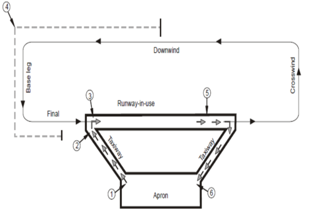
Figure 1
GM6 ATS.TR.210(a)(3) Operation of air traffic control service
ED Decision 2020/008/R
AERODROME CONTROL — PRIORITY FOR DEPARTURE
Departures should normally be cleared in the order in which aircraft are ready for take-off, except that deviations may be made from this order of priority to facilitate the maximum number of departures with the least average delay. Factors which should be considered in relation to the departure sequence include, inter alia:
(a) types of aircraft and their relative performance;
(b) routes to be followed after take-off;
(c) any specified minimum departure interval between take-offs;
(d) need to apply wake turbulence separation minima;
(e) aircraft which should be afforded priority; and
(f) aircraft subject to ATFM requirements.
GM7 ATS.TR.210(a)(3) Operation of air traffic control service
ED Decision 2020/008/R
AERODROME CONTROL — PRIORITY FOR DEPARTURE AND ATFM MEASURES
For aircraft subject to ATFM requirements, it is the responsibility of the pilot and the operator to ensure that the aircraft is ready to taxi in time to meet any required departure time, bearing in mind that once a departure sequence is established on the taxiway system, it can be difficult, and sometimes impossible, to change the order.
GM1 ATS.TR.210(b) Operation of air traffic control service
ED Decision 2020/008/R
CLEARANCES TO FLY MAINTAINING OWN SEPARATION WHILE IN VISUAL METEOROLOGICAL CONDITIONS
(a) If there is a possibility that flight under visual meteorological conditions (VMC) may become impracticable, an IFR flight should be provided with alternative instructions to be complied with in the event that flight in VMC cannot be maintained for the term of the clearance.
(b) The pilot of an IFR flight, on observing that conditions are deteriorating and considering that operation in VMC will become impossible, should inform the air traffic control unit before entering instrumental meteorological conditions (IMC) and should proceed in accordance with the alternative instructions given.
GM2 ATS.TR.210(b) Operation of air traffic control service
ED Decision 2020/008/R
CLEARANCES TO FLY MAINTAINING OWN SEPARATION WHILE IN VISUAL METEOROLOGICAL CONDITIONS
(a) The provision of vertical or horizontal separation by an air traffic unit is not applicable in respect of any specified portion of a flight cleared subject to maintaining own separation and remaining in VMC. It is for the aircraft so cleared to ensure, for the duration of the clearance, that it is not operated in such proximity to other flights as to create a collision hazard.
(b) It is axiomatic that a VFR flight must remain in VMC at all times. Accordingly, the issuance of a clearance to a VFR flight to fly subject to maintaining own separation and remaining in VMC has no other object than to signify that, for the duration of the clearance, separation from other aircraft by air traffic control unit is not provided.
(c) It should be noted that the objectives of the air traffic control service as prescribed in ATS.TR.100 do not include prevention of collision with terrain. Pilots are responsible for ensuring that any clearances issued by air traffic control units are safe in this respect. When vectoring or assigning a direct routing not included in the flight plan, which takes an IFR flight off published ATS route or instrument procedure, the procedures in point (a)(5) of ATS.TR.235 apply.
AMC1 ATS.TR.210(c) Operation of air traffic control service
ED Decision 2020/008/R
EMERGENCY SEPARATION APPLICATION
(a) If, during an emergency situation, it is not possible to ensure that the applicable horizontal separation can be maintained, emergency separation of half the applicable vertical separation minimum may be used, i.e. a nominal 150 m (500 ft) between aircraft in airspace where a vertical separation minimum of 300 m (1 000 ft) is applied, and a nominal 300 m (1 000 ft) between aircraft in airspace where a 600 m (2 000 ft) vertical separation minimum is applied.
(b) When emergency separation is applied, the flight crews concerned should be advised that emergency separation is being applied, and informed of the actual minimum used. Additionally, all flight crews concerned should be provided with essential traffic information.
GM1 to AMC1 ATS.TR.210(c) Operation of air traffic control service
ED Decision 2020/008/R
SEPARATION APPLICATION IN CASE OF ATS SURVEILLANCE SYSTEM FAILURE
As an emergency measure, in the event of complete failure of the ATS surveillance system where air-ground communications remain, the use of flight levels spaced by half the applicable vertical separation minimum may be resorted to temporarily if standard procedural separation cannot be provided immediately.
GM2 ATS.TR.210(c) Operation of air traffic control service
ED Decision 2020/008/R
PROCEDURAL SEPARATION — APPLICATION OF LARGER SEPARATION MINIMA UNDER SPECIFIC CIRCUMSTANCES
Larger separations than the specified minima should be applied whenever exceptional circumstances such as unlawful interference or navigational difficulties call for extra precautions. This should be done with due regard to all relevant factors so as to avoid impeding the flow of air traffic by the application of excessive separations.
AMC1 ATS.TR.210(c)(1) Operation of air traffic control
ED Decision 2020/008/R
PROCEDURAL SEPARATION — SEPARATION OF AIRCRAFT HOLDING IN FLIGHT
(a) Aircraft established in adjacent holding patterns should, except when lateral separation between the holding areas exists as determined by the air traffic services provider and approved by the competent authority, be separated by the applicable vertical separation minimum.
(b) Except when lateral separation exists, the air traffic controller should apply vertical separation between aircraft holding in flight and other aircraft, whether arriving, departing or en-route, whenever the other aircraft concerned are within 5 minutes flying time of the holding area or within a distance established by the air traffic services provider and approved by the competent authority (see Figure 2).
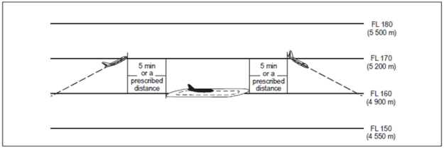
Figure 2 Separation between holding aircraft and en-route aircraft
GM1 to AMC1 ATS.TR.210(c)(1) Operation of air traffic control service
ED Decision 2020/008/R
SEPARATION OF AIRCRAFT HOLDING IN FLIGHT
Criteria and procedures for the simultaneous use of adjacent holding patterns should be prescribed in local instructions.
GM1 ATS.TR.210(c)(1) Operation of air traffic control service
ED Decision 2020/008/R
VERTICAL SEPARATION APPLICATION
Vertical separation is obtained by requiring aircraft using prescribed altimeter setting procedures to operate at different levels expressed in terms of flight levels or altitudes, in accordance with the provisions in ATS.TR.125, ATS.TR.130, ATS.TR.135 and ATS.TR.140.
GM2 ATS.TR.210(c)(1) Operation of air traffic control service
ED Decision 2020/008/R
APPLICATION OF VERTICAL SEPARATION DURING CLIMB OR DESCENT
(a) An aircraft may be cleared to a level previously occupied by another aircraft after the latter has reported vacating it, except when:
(1) severe turbulence is known to exist;
(2) the higher aircraft is effecting a cruise climb; or
(3) the difference in aircraft performance is such that less than the applicable separation minimum may result;
in which case such clearance should be withheld until the aircraft vacating the level has reported at or passing another level separated by the required minimum.
(b) When the aircraft concerned are entering or established in the same holding pattern, consideration should be given to aircraft descending at markedly different rates and, if necessary, additional measures such as specifying a maximum descent rate for the higher aircraft and a minimum descent rate for the lower aircraft should be applied to ensure that the required separation is maintained.
GM3 ATS.TR.210(c)(1) Operation of air traffic control service
ED Decision 2020/008/R
GEOMETRIC HEIGHT INFORMATION
Geometric height information is generated by airborne systems such as, for instance, GPS or radio altimeters.
AMC1 ATS.TR.210(c)(2) Operation of air traffic control service
ED Decision 2020/008/R
HORIZONTAL SEPARATION MINIMA BASED ON ATS SURVEILLANCE SYSTEM
(a) Unless otherwise prescribed in accordance with point (b), or AMC6 ATS.TR.220, or point (d) of AMC7 ATS.TR.220, or ATS.TR.255, the horizontal separation minimum based on radar and/or ADS-B and/or MLAT systems should be 9.3 km (5.0 NM).
(b) If so established by the air traffic services provider and approved by the competent authority, the separation minimum in point (a) may be reduced but not below:
(1) 5.6 km (3.0 NM) when radar and/or ADS-B and/or MLAT systems’ capabilities at a given location so permit; and
(2) 4.6 km (2.5 NM) between succeeding aircraft which are established on the same final approach track within 18.5 km (10 NM) of the runway threshold. A reduced separation minimum of 4.6 km (2.5 NM) may be applied, provided:
(i) the average runway occupancy time of landing aircraft is proven, by means such as data collection and statistical analysis and methods based on a theoretical model, not to exceed 50 seconds;
(ii) braking action is reported as good and runway occupancy times are not adversely affected by runway contaminants such as slush, snow or ice;
(iii) an ATS surveillance system with appropriate azimuth and range resolution and an update rate of 5 seconds or less is used in combination with suitable displays;
(iv) the aerodrome air traffic controller is able to observe, visually or by means of surface movement radar (SMR), MLAT system or a surface movement guidance and control system (SMGCS), the runway-in-use and associated exit and entry taxiways;
(v) wake turbulence separation minima in AMC6 ATS.TR.220 or in point (d) of AMC7 ATS.TR.220, or as may be prescribed by the air traffic services provider and approved by the competent authority (e.g. for specific aircraft types), do not apply;
(vi) aircraft approach speeds are closely monitored by the air traffic controller and when necessary adjusted so as to ensure that separation is not reduced below the minimum;
(vii) aircraft operators and pilots have been made fully aware of the need to exit the runway in an expeditious manner whenever the reduced separation minimum on final approach is applied; and
(viii) procedures concerning the application of the reduced minimum are published in AIPs.
GM1 to AMC1 ATS.TR.210(c)(2) Operation of air traffic control service
ED Decision 2020/008/R
CRITERIA FOR APPLICATION OF HORIZONTAL SEPARATION BASED ON RADAR AND/OR ADS-B AND/OR MLAT SYSTEMS
(a) The separation minimum or minima based on radar and/or ADS-B and/or MLAT systems to be applied should be prescribed by the air traffic services provider and approved by the competent authority according to the capability of the particular ATS surveillance system or sensor to accurately identify the aircraft position in relation to the centre of a position symbol, PSR blip, SSR response and taking into account factors which may affect the accuracy of the ATS surveillance system-derived information, such as aircraft range from the radar site and the range scale of the situation display in use.
(b) Separation based on the use of ADS-B, SSR and/or MLAT, and/or PSR position symbols and/or PSR blips should be applied so that the distance between the centres of the position symbols and/or PSR blips, representing the positions of the aircraft concerned, is never less than a prescribed minimum.
(c) Separation based on the use of PSR blips and SSR responses should be applied so that the distance between the centre of the PSR blip and the nearest edge of the SSR response (or centre, when authorised by the competent authority) is never less than a prescribed minimum.
(d) Separation based on the use of ADS-B position symbols and SSR responses should be applied so that the distance between the centre of the ADS-B position symbol and the nearest edge of the SSR response (or the centre, when authorised by the competent authority) is never less than a prescribed minimum.
(e) Separation based on the use of SSR responses should be applied so that the distance between the closest edges of the SSR responses (of the centres, when authorised by the competent authority) is never less than a prescribed minimum.
(f) In no circumstances should the edges of the position indications touch or overlap unless vertical separation is applied between the aircraft concerned, irrespective of the type of position indication displayed and separation minimum applied.
AMC2 ATS.TR.210(c)(2) Operation of air traffic control service
ED Decision 2020/008/R
SPECIFIC CONDITIONS AND LIMITATIONS FOR THE APPLICATION OF SEPARATION MINIMA BASED ON ATS SURVEILLANCE SYSTEM
(a) The separation minima based on ATS surveillance systems specified in AMC1 ATS.TR.210(c)(2), AMC6 ATS.TR.220 and point (d) of AMC7 ATS.TR.220 may be applied between an aircraft taking off and a preceding departing aircraft or other identified traffic, provided there is reasonable assurance that the departing aircraft will be identified within 2 km (1 NM) from the end of the runway, and that, at the time, the required separation will exist.
(b) The separation minima specified based on ATS surveillance systems should not be applied between aircraft holding over the same holding fix.
AMC3 ATS.TR.210(c)(2) Operation of air traffic control service
ED Decision 2020/008/R
PROCEDURAL SEPARATION — REDUCTION IN LATERAL AND LONGITUDINAL SEPARATION MINIMA
(a) Provided that prior consultation with airspace users is undertaken and that an appropriate safety assessment has shown that an acceptable level of safety is maintained, the lateral and longitudinal separation minima established in:
— AMC6 ATS.TR.210(c)(2)(i); and
may be reduced in the following circumstances:
(1) when special electronic or other aids enable the pilot-in-command of an aircraft to determine accurately the aircraft’s position and when adequate communication facilities exist for that position to be transmitted without delay to the appropriate air traffic control unit; or
(2) when, in association with rapid and reliable communication facilities, information of an aircraft’s position, derived from an ATS surveillance system, is available to the appropriate air traffic control unit; or
(3) when RNAV-equipped aircraft operate within the coverage of electronic aids that provide the necessary updates to maintain navigation accuracy.
(b) In addition to the circumstances mentioned in point (a), the lateral and longitudinal separation minima established in:
— AMC6 ATS.TR.210(c)(2)(i); and
may be reduced in the vicinity of aerodromes if:
(1) adequate separation can be provided by the aerodrome air traffic controller when each aircraft is continuously visible to this air traffic controller; or
(2) each aircraft is continuously visible to flight crews of the other aircraft concerned and the pilots thereof report that they can maintain their own separation; or
(3) in the case of one aircraft following another, the flight crew of the succeeding aircraft reports that the other aircraft is in sight and separation can be maintained.
GM1 ATS.TR.210(c)(2)(i) Operation of air traffic control service
ED Decision 2020/008/R
PROCEDURAL SEPARATION — LONGITUDINAL SEPARATION APPLICATION
(a) Longitudinal separation should be applied so that the spacing between the estimated positions of the aircraft being separated is never less than a prescribed minimum. Longitudinal separation between aircraft following the same or diverging tracks may be maintained by application of speed control, including the Mach number technique. When applicable, use of the Mach number technique should be prescribed on the basis of a regional air navigation agreement.
(b) Longitudinal separation between supersonic aircraft during the transonic acceleration and supersonic phases of flight should normally be established by appropriate timing of the start of transonic acceleration rather than by the imposition of speed restrictions in supersonic flight.
(c) Time-based separation applied in accordance with AMC1 ATS.TR.210(c)(2)(i), AMC2 ATS.TR.210(c)(2)(i) and AMC5 ATS.TR.210(c)(2)(i) may be based on position information and estimates derived from voice reports, controller-pilot data link communications (CPDLC) or ADS-C.
(d) For the purpose of application of longitudinal separation, the terms ‘same track’, ‘reciprocal tracks’ and ‘crossing tracks’ have the following meanings:
(1) Same track (see Figure 3)
Same direction tracks and intersecting tracks or portions thereof, the angular difference of which is less than 45 degrees or more than 315 degrees, and whose protected airspaces overlap
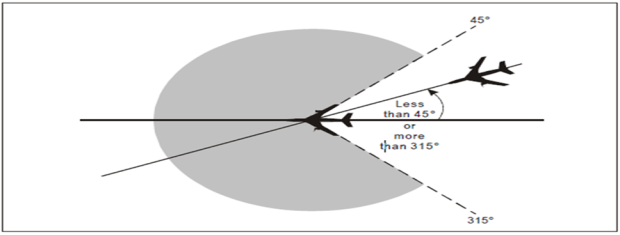 Figure 3: Aircraft on same track
(2) Reciprocal tracks (see Figure 4)
Opposite tracks and intersecting tracks or portions thereof, the angular difference of which is more than 135 degrees but less than 225 degrees, and whose protected airspaces overlap
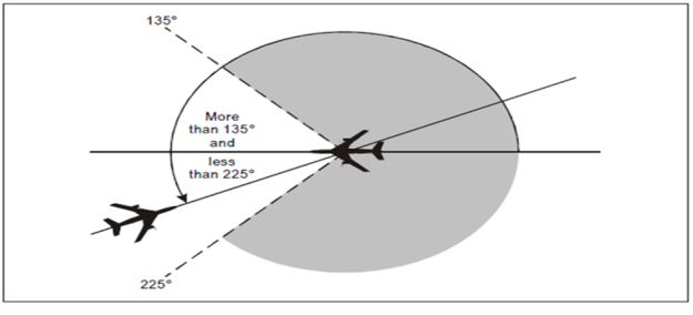
Figure 4: Aircraft on reciprocal tracks
(3) Crossing tracks (see Figure 5)
Intersecting tracks or portions thereof other than those specified in points (1) and (2)
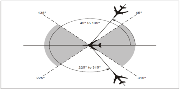
Figure 5: Aircraft on crossing tracks
AMC1 ATS.TR.210(c)(2)(i) Operation of air traffic control service
ED Decision 2020/008/R
PROCEDURAL SEPARATION — LONGITUDINAL SEPARATION MINIMA BASED ON TIME — AIRCRAFT MAINTAINING THE SAME LEVEL
For aircraft flying at the same level, the longitudinal separation minima based on time should be one of the following:
(a) Aircraft flying on the same track and same level
(1) 15 minutes (see Figure 6); or
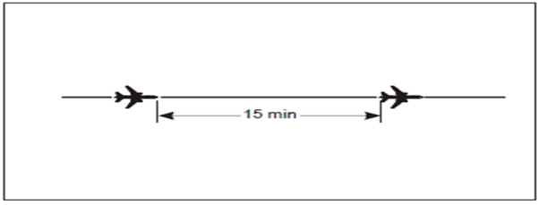
Figure 6: 15-minute separation between aircraft on the same track and same level
(2) 10 minutes if navigation aids permit frequent determination of position and speed (see Figure 7); or
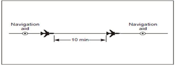
Figure 7: 10-minute separation between aircraft on the same track and same level
(3) 5 minutes in the following cases, provided that in each case the preceding aircraft is maintaining a TAS of 37 km/h (20 kt) or more faster than the succeeding aircraft (see Figure 8)
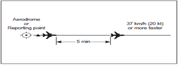
Figure 8: 5-minute separation between aircraft on the same track and same level
(i) between aircraft that have departed from the same aerodrome;
(ii) between en-route aircraft that have reported over the same exact significant point;
(iii) between departing and en-route aircraft after the en-route aircraft has reported over a fix that it is so located in relation to the departure point as to ensure that 5-minute separation can be established at the point the departing aircraft will join the air route; or
(4) 3 minutes in the cases listed under point (a)(3), provided that in each case the preceding aircraft is maintaining a TAS of 74 km/h (40 kt) or more faster than the succeeding aircraft (see Figure 9)
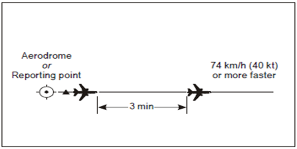
Figure 9: 3-minute separation between aircraft on the same track and same level
(b) Aircraft flying on crossing tracks
(1) 15 minutes at the point of intersection of the tracks (see Figure 10); or
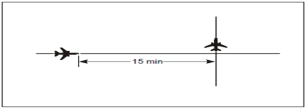
Figure 10: 15-minute separation between aircraft on crossing tracks and same level
(2) 10 minutes if navigation aids permit frequent determination of position and speed (see Figure 11).
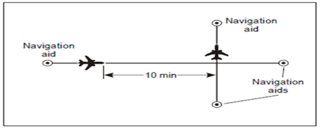
Figure 11: 10-minute separation between aircraft on crossing tracks and same level
AMC2 ATS.TR.210(c)(2)(i) Operation of air traffic control service
ED Decision 2020/008/R
PROCEDURAL SEPARATION — LONGITUDINAL SEPARATION MINIMA BASED ON TIME — AIRCRAFT CLIMBING OR DESCENDING
For aircraft climbing or descending, the longitudinal separation minima based on time should be one of the following:
a) Aircraft on the same track
When an aircraft will pass through the level of another aircraft on the same track, the following minimum longitudinal separation should be provided:
(1) 15 minutes while vertical separation does not exist (see Figures 12 and 13); or
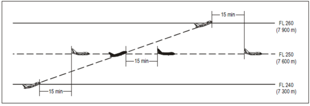
Figure 12: 15-minute separation between aircraft climbing and on the same track

Figure 13: 15-minute separation between aircraft descending and on the same track
(2) 10 minutes while vertical separation does not exist, provided that such separation is authorised only where ground-based navigation aids or GNSS permit frequent determination of position and speed (see Figures 14 and 15); or
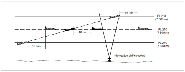
Figure 14: 10-minute separation between aircraft climbing and on the same track
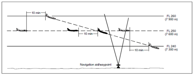
Figure 15: 10-minute separation between aircraft descending and on the same track
(3) 5 minutes while vertical separation does not exist, provided that:
(i) the level change is commenced within 10 minutes of the time the second aircraft has reported over a common point which should be derived from ground-based navigation aids or by GNSS; and
(ii) when issuing the clearance through third-party communication or CPDLC, a restriction should be added to the clearance to ensure that the 10-minute condition is satisfied (see Figures 16 and 17).
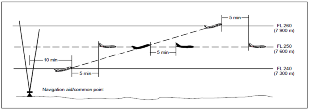
Figure 16: 5-minute separation between aircraft climbing and on the same track
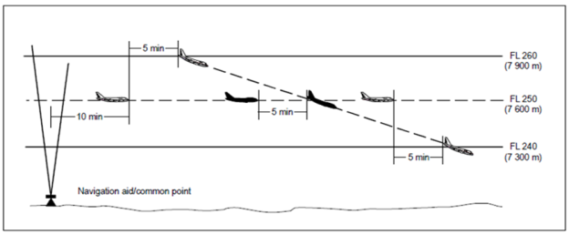
Figure 17: 5-minute separation between aircraft descending and on the same track
b) Aircraft on crossing tracks
(1) 15 minutes while vertical separation does not exist (see Figures 18 and 19); or
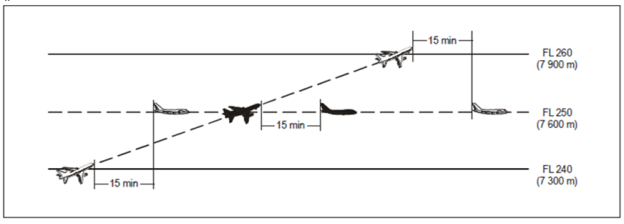
Figure 18: 15-minute separation between aircraft climbing and on crossing tracks
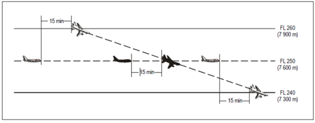
Figure 19: 15-minute separation between aircraft descending and on crossing tracks
(2) 10 minutes while vertical separation does not exist if navigation aids permit frequent determination of position and speed (see Figures 20 and 21).
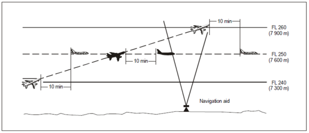
Figure 20: 10-minute separation between aircraft climbing and on crossing tracks
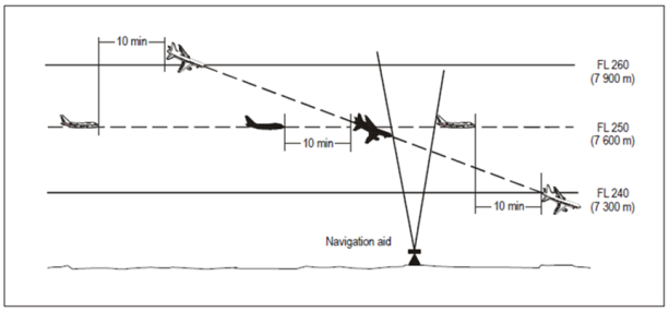
Figure 21: 10-minute separation between aircraft descending and on crossing tracks
c) Aircraft on reciprocal tracks
Where lateral separation is not provided, vertical separation should be provided for at least 10 minutes prior to and after the time the aircraft are estimated to pass, or are estimated to have passed (see Figure 22). Provided it has been determined that the aircraft have passed each other, this minimum need not apply.

Figure 22: 10-minute separation between aircraft on reciprocal tracks
AMC3 ATS.TR.210(c)(2)(i) Operation of air traffic control service
ED Decision 2020/008/R
PROCEDURAL SEPARATION — LONGITUDINAL SEPARATION MINIMA BASED ON DISTANCE USING DISTANCE MEASURING EQUIPMENT (DME) AND/OR GNSS — AIRCRAFT AT THE SAME CRUISING LEVEL
Longitudinal separation minima based on distance using distance measuring equipment (DME) and/or GNSS should be established between aircraft at the same cruising level, as follows:
(a) Aircraft on the same track
(1) 37 km (20 NM), provided:
(i) each aircraft utilises:
(A) the same ‘on-track’ DME station when both aircraft are utilising DME; or
(B) an ‘on-track’ DME station and a collocated waypoint when one aircraft is utilising DME and the other is utilising GNSS; or
(C) the same waypoint when both aircraft are utilising GNSS; and
(ii) separation is checked by obtaining simultaneous DME and/or GNSS readings from the aircraft at frequent intervals to ensure that the minimum will not be infringed (see Figure 23);
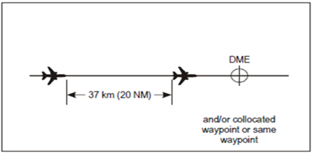
Figure 23: 37 km (20 NM) DME and/or GNSS-based separation between aircraft on the same track and same level
(2) 19 km (10 NM), provided:
(i) the leading aircraft maintains a TAS of 37 km/h (20 kt) or more faster than the succeeding aircraft;
(ii) each aircraft utilises:
(A) the same ‘on-track’ DME station when both aircraft are utilising DME; or
(B) an ‘on-track’ DME station and a collocated waypoint when one aircraft is utilising DME and the other is utilising GNSS; or
(C) the same waypoint when both aircraft are utilising GNSS; and
(iii) separation is checked by obtaining simultaneous DME and/or GNSS readings from the aircraft at such intervals as are necessary to ensure that the minimum is established and will not be infringed (see Figure 24).
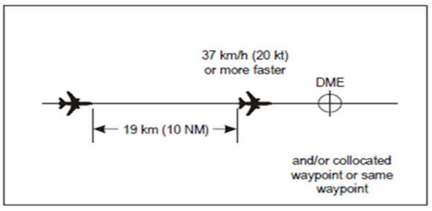
Figure 24: 19 km (10 NM) DME and/or GNSS-based separation between aircraft on the same track and same level
(b) Aircraft on crossing tracks
The longitudinal separation prescribed in point (a) should also apply, provided each aircraft reports distance from the DME station and/or collocated waypoint or same waypoint located at the crossing point of the tracks and that the relative angle between the tracks is less than 90 degrees (see Figures 25 and 26).
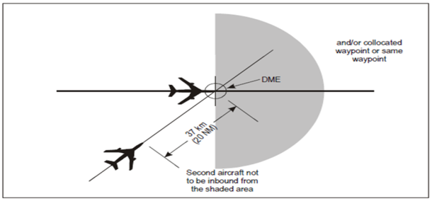
Figure 25: 37 km (20 NM) DME and/or GNSS-based separation between aircraft on crossing tracks and the same level
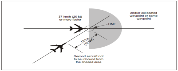
Figure 26: 19 km (10 NM) DME and/or GNSS-based separation between aircraft on crossing tracks and the same level
AMC4 ATS.TR.210(c)(2)(i) Operation of air traffic control service
ED Decision 2020/008/R
PROCEDURAL SEPARATION — LONGITUDINAL SEPARATION MINIMA BASED ON DISTANCE USING DISTANCE MEASURING EQUIPMENT (DME) AND/OR GNSS — AIRCRAFT CLIMBING OR DESCENDING
Longitudinal separation minima based on distance using distance measuring equipment (DME) AND/OR GNSS should be established between aircraft climbing or descending, as follows:
(a) Aircraft on the same track
19 km (10 NM) while vertical separation does not exist, provided:
(1) each aircraft utilises:
(i) the same ‘on-track’ DME station when both aircraft are utilising DME; or
(ii) an ‘on-track’ DME station and a collocated waypoint when one aircraft is utilising DME and the other is utilising GNSS; or
(iii) the same waypoint when both aircraft are utilising GNSS; and
(2) one aircraft maintains a level while vertical separation does not exist; and
(3) separation is established by obtaining simultaneous DME and/or GNSS readings from the aircraft (see Figures 27 and 28).
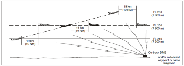
Figure 27: 19 km (10 NM) DME and/or GNSS-based separation between aircraft climbing and on the same track
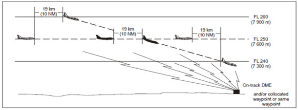
Figure 28: 19 km (10 NM) DME and/or GNSS-based separation between aircraft descending and on the same track
(b) Aircraft on reciprocal tracks
Aircraft utilising on-track DME and/or collocated waypoint or same waypoint may be cleared to climb or descend through the levels occupied by other aircraft utilising on-track DME and/or collocated waypoint or same waypoint, provided that it has been positively established that the aircraft have passed each other and are at least 10 NM apart, or such other value determined by the air traffic services provider and approved by the competent authority.
GM1 to AMC3 ATS.TR.210(c)(2)(i) and AMC4 ATS.TR.210(c)(2)(i) Operation of air traffic control service
ED Decision 2020/008/R
PROCEDURAL SEPARATION — LONGITUDINAL SEPARATION MINIMA BASED ON DISTANCE USING DISTANCE MEASURING EQUIPMENT (DME) AND/OR GNSS — APPLICATION
(a) Where the term ‘on track’ is used in the provisions relating to the application of longitudinal separation minima using DME and/or GNSS, it means that the aircraft is flying either directly inbound to or directly outbound from the station/waypoint.
(b) Separation should be established by maintaining not less than the specified distance(s) between aircraft positions as reported by reference to DME in conjunction with other appropriate navigation aids and/or GNSS. This type of separation should be applied between two aircraft using DME, or two aircraft using GNSS, or one aircraft using DME and one aircraft using GNSS. Direct controller-pilot VHF voice communication should be maintained while such separation is used.
(c) For the purpose of applying GNSS-based separation minimum, a distance derived from an integrated navigation system incorporating GNSS input is regarded as equivalent to GNSS distance.
(d) When applying these separation minima between any aircraft with area navigation capability, air traffic controllers should specifically request GNSS-derived distance.
AMC5 ATS.TR.210(c)(2)(i) Operation of air traffic control service
ED Decision 2020/008/R
PROCEDURAL SEPARATION — LONGITUDINAL SEPARATION MINIMA WITH MACH NUMBER TECHNIQUE BASED ON TIME
When the Mach number technique is applied and provided that:
(a) the aircraft concerned have reported over the same common point and follow the same track or continuously diverging tracks until some other form of separation is provided; or
(b) if the aircraft have not reported over the same common point and it is possible to ensure, by radar, ADS-B or other means, that the appropriate time interval will exist at the common point from which they either follow the same track or continuously diverging tracks,
minimum longitudinal separation between turbojet aircraft on the same track, whether in level, climbing or descending flight should be:
(1) 10 minutes. In this case, the preceding aircraft should maintain a true Mach number equal to or greater than that maintained by the following aircraft; or
(2) between 9 and 5 minutes inclusive, provided that the preceding aircraft is maintaining a true Mach number greater than the following aircraft in accordance with the following:
(i) 9 minutes if the preceding aircraft is Mach 0.02 faster than the following aircraft;
(ii) 8 minutes if the preceding aircraft is Mach 0.03 faster than the following aircraft;
(iii) 7 minutes if the preceding aircraft is Mach 0.04 faster than the following aircraft;
(iv) 6 minutes if the preceding aircraft is Mach 0.05 faster than the following aircraft;
(v) 5 minutes if the preceding aircraft is Mach 0.06 faster than the following aircraft.
AMC6 ATS.TR.210(c)(2)(i) Operation of air traffic control service
ED Decision 2020/008/R
PROCEDURAL SEPARATION — LONGITUDINAL SEPARATION MINIMA WITH MACH NUMBER TECHNIQUE BASED ON DISTANCE USING RNAV
(a) The air traffic controller should not apply RNAV distance-based separation minima after having received pilot advice indicating navigation equipment deterioration or failure.
(b) A 150 km (80 NM) RNAV distance-based separation minimum with Mach number technique may be used on same-direction tracks in lieu of a 10-minute longitudinal separation minimum with Mach number technique, provided that:
(1) each aircraft reports its distance to or from the same ‘on-track’ common point;
(2) separation between aircraft at the same level is checked by obtaining simultaneous RNAV distance readings from the aircraft at frequent intervals to ensure that the minimum will not be infringed (see Figure 29);

Figure 29: 150 km (80 NM) RNAV-based separation between aircraft at the same level
(3) separation between aircraft climbing or descending is established by obtaining simultaneous RNAV distance readings from the aircraft (see Figures 30 and 31); and
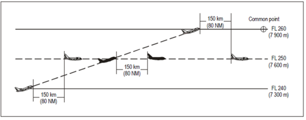
Figure 30: 150 km (80 NM) RNAV-based separation between aircraft climbing and on the same track
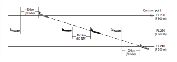
Figure 31: 150 km (80 NM) RNAV-based separation between aircraft descending and on the same track
(4) in the case of aircraft climbing or descending, one aircraft maintains a level while vertical separation does not exist.
(c) Aircraft on reciprocal tracks
Aircraft utilising RNAV may be cleared to climb or descend to or through the levels occupied by other aircraft utilising RNAV, provided it has been positively established by simultaneous RNAV distance readings to or from the same ‘on-track’ common point that the aircraft have passed each other and are at least 150 km (80 NM) apart (see Figure 32).
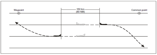
Figure 32: 150 km (80 NM) RNAV-based separation between aircraft on reciprocal tracks
GM1 to AMC5 ATS.TR.210(c)(2)(i) and AMC6 ATS.TR.210(c)(2)(i) Operation of air traffic control service
ED Decision 2020/008/R
PROCEDURAL SEPARATION — LONGITUDINAL SEPARATION MINIMA WITH MACH NUMBER TECHNIQUE
Guidance on the application of the Mach number technique for separation of subsonic aircraft is available in ICAO Doc 9426 ‘Air Traffic Services Planning Manual’.
GM1 to AMC6 ATS.TR.210(c)(2)(i) Operation of air traffic control service
ED Decision 2020/008/R
LONGITUDINAL SEPARATION MINIMA WITH MACH NUMBER TECHNIQUE BASED ON DISTANCE USING RNAV — APPLICATION
(a) Separation should be established by maintaining not less than the specified distance between aircraft positions as reported by reference to RNAV equipment. Direct controller-pilot communications should be maintained, while such separation is used. Where high-frequency or general-purpose extended-range VHF air-ground communication channels are used for area control service and are worked by air-ground communicators, suitable arrangements should be made to permit direct controller-pilot communications, or monitoring by the air traffic controller of all air-ground communications.
(b) To assist pilots to readily provide the required RNAV distance information, such position reports should, wherever possible, be referenced to a common waypoint ahead of both aircraft.
(c) RNAV distance-based separation may be applied between RNAV-equipped aircraft when operating on designated RNAV routes or on ATS routes defined by VOR.
(d) To facilitate application of the procedure where a considerable change of level is involved, a descending aircraft may be cleared to some convenient level above the lower aircraft, or a climbing aircraft to some convenient level below the higher aircraft, to permit a further check on the separation that will be obtained while vertical separation does not exist.
AMC7 ATS.TR.210(c)(2)(i) Operation of air traffic control service
ED Decision 2020/008/R
RUNWAY SEPARATION MINIMA BETWEEN DEPARTING AIRCRAFT AND OTHER AIRCRAFT USING THE SAME RUNWAY
Except as provided in AMC9 ATS.TR.210(c)(2)(i) as regards reduced runway separation minima between aircraft using the same runway, and in ATS.TR.220 as regards time-based wake turbulence separation minima, the aerodrome control tower should not permit a departing aircraft to commence take-off until:
(a) the preceding departing aircraft has crossed the end of the runway-in-use; or
(b) the preceding departing aircraft has started a turn; or
(c) all preceding landing aircraft are clear of the runway-in-use (see Figure 33).
Position limits to be reached by a landed aircraft (A) or a departing aircraft (B or C) before an arriving aircraft may be cleared to cross the threshold of the runway-in-use or a departing aircraft may be cleared to take off, unless otherwise prescribed.
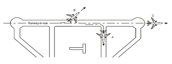
Figure 33: Separation between departing and arriving aircraft
AMC8 ATS.TR.210(c)(2)(i) Operation of air traffic control service
ED Decision 2020/008/R
RUNWAY SEPARATION OF LANDING AIRCRAFT AND PRECEDING LANDING AND DEPARTING AIRCRAFT USING THE SAME RUNWAY
Except as provided AMC9 ATS.TR.210(c)(2)(i) as regards reduced runway separation minima between aircraft using the same runway, and in ATS.TR.220 as regards time-based wake turbulence separation minima, the aerodrome control tower should not permit a landing aircraft to cross the runway threshold on its final approach until:
(a) the preceding departing aircraft has crossed the end of the runway-in-use; or
(b) the preceding departing aircraft has started a turn; or
(c) all preceding landing aircraft are clear of the runway-in-use (see Figure 33).
AMC9 ATS.TR.210(c)(2)(i) Operation of air traffic control service
ED Decision 2020/008/R
REDUCED RUNWAY SEPARATION MINIMA BETWEEN AIRCRAFT USING THE SAME RUNWAY
(a) The air traffic services provider may prescribe lower minima than those established in AMC7 ATS.TR.210(c)(2)(i) concerning separation of departing aircraft, and in AMC8 ATS.TR.210(c)(2)(i) concerning separation of landing aircraft and preceding landing and departing aircraft using the same runway, after consultation with the operators. The safety assessment to be performed in support of the application of reduced separation minima should be carried out for each runway for which the reduced minima are intended, taking into account factors such as:
(1) runway length;
(2) aerodrome layout; and
(3) types/categories of aircraft involved.
(b) Reduced runway separation minima should only be applied during the hours of daylight from 30 minutes after local sunrise to 30 minutes before local sunset.
(c) For the purpose of reduced runway separation, aircraft should be classified as follows:
(1) Category 1 aircraft: single-engine propeller aircraft with a maximum certificated take-off mass (MCTOM) of 2 000 kg or less;
(2) Category 2 aircraft: single-engine propeller aircraft with a maximum certificated take-off mass of more than 2 000 kg but less than 7 000 kg; and twin-engine propeller aircraft with a maximum certificated take-off mass of less than 7 000 kg; and
(3) Category 3 aircraft: all other aircraft.
(d) Reduced runway separation minima should not apply between a departing aircraft and a preceding landing aircraft.
(e) Reduced runway separation minima should be subject to the following conditions:
(1) wake turbulence separation minima should be applied;
(2) visibility should be at least 5 km and ceiling shall not be lower than 300 m (1 000 ft);
(3) tailwind component should not exceed 5 kt;
(4) there should be available means, such as suitable landmarks, to assist the air traffic controller in assessing the distances between aircraft. A surface movement ATS surveillance system that provides the air traffic controller with position information on aircraft may be utilised, provided that approval for operational use of such equipment includes a safety assessment to ensure that all requisite operational and performance requirements are met;
(5) minimum separation continues to exist between two departing aircraft immediately after take-off of the second aircraft;
(6) traffic information should be provided to the flight crew of the succeeding aircraft concerned; and
(7) the braking action should not be adversely affected by runway contaminants such as ice, slush, snow and water.
(f) Reduced runway separation minima which may be applied at an aerodrome should be determined for each separate runway. The separation to be applied should in no case be less than the following minima:
(1) landing aircraft:
(i) a succeeding landing Category 1 aircraft may cross the runway threshold when the preceding aircraft is a Category 1 or 2 aircraft which either:
(A) has landed and has passed a point at least 600 m from the threshold of the runway, is in motion and will vacate the runway without backtracking; or
(B) is airborne and has passed a point at least 600 m from the threshold of the runway;
(ii) a succeeding landing Category 2 aircraft may cross the runway threshold when the preceding aircraft is a Category 1 or 2 aircraft which either:
(A) has landed and has passed a point at least 1 500 m from the threshold of the runway, is in motion and will vacate the runway without backtracking; or
(B) is airborne and has passed a point at least 1 500 m from the threshold of the runway;
(iii) a succeeding landing aircraft may cross the runway threshold when a preceding Category 3 aircraft:
(A) has landed and has passed a point at least 2 400 m from the threshold of the runway, is in motion and will vacate the runway without backtracking; or
(B) is airborne and has passed a point at least 2 400 m from the threshold of the runway;
(2) departing aircraft:
(i) a Category 1 aircraft may be cleared for take-off when the preceding departing aircraft is a Category 1 or 2 aircraft which is airborne and has passed a point at least 600 m from the position of the succeeding aircraft;
(ii) a Category 2 aircraft may be cleared for take-off when the preceding departing aircraft is a Category 1 or 2 aircraft which is airborne and has passed a point at least 1 500 m from the position of the succeeding aircraft; and
(iii) an aircraft may be cleared for take-off when a preceding departing Category 3 aircraft is airborne and has passed a point at least 2 400 m from the position of the succeeding aircraft.
AMC10 ATS.TR.210(c)(2)(i) Operation of air traffic control service
ED Decision 2020/008/R
PROCEDURAL CONTROL — MINIMUM SEPARATION BETWEEN DEPARTING AIRCRAFT
(a) The aerodrome air traffic controller should apply a 1-minute separation if aircraft are to fly on tracks diverging by at least 45 degrees immediately after take-off so that lateral separation is provided (see Figure 34).
(b) When:
(1) aircraft are using parallel runways; or
(2) in a context of operations on diverging runways which do not cross, the pilot has accepted a take-off direction which is not into the wind, in accordance with the procedure described in point (b) of GM1 ATS.TR.260,
this minimum may be reduced, provided instructions covering the procedure have been established by the air traffic services provider and approved by the competent authority and lateral separation is effected immediately after take-off.
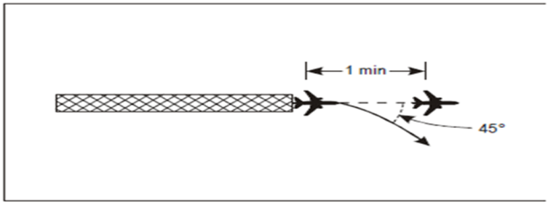
Figure 34: 1-minute separation between departing aircraft following tracks diverging by at least 45 degrees
(c) The air traffic controller should apply a 2-minute separation between take-offs when the preceding aircraft is 74 km/h (40 kt) or more faster than the succeeding aircraft and both aircraft will follow the same track (see Figure 35).
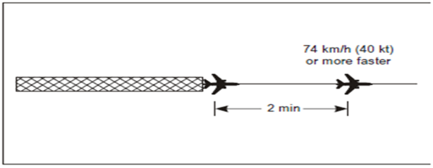
Figure 35: 2-minute separation between aircraft following the same track
(d) The air traffic controller should apply a 5-minute separation while vertical separation does not exist if a departing aircraft will be flown through the level of a preceding departing aircraft and both aircraft propose to follow the same track (see Figure 36). The air traffic controller should take action to ensure that the 5-minute separation will be maintained or increased while vertical separation does not exist.
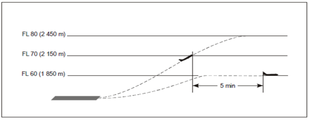
Figure 36: 5-minute separation of departing aircraft following the same track
AMC11 ATS.TR.210(c)(2)(i) Operation of air traffic control service
ED Decision 2020/008/R
PROCEDURAL CONTROL — SEPARATION OF DEPARTING AIRCRAFT FROM ARRIVING AIRCRAFT
The following separation should be applied when take-off clearance is based on the position of an arriving aircraft:
(a) If an arriving aircraft is making a complete instrument approach, a departing aircraft may take off:
(1) in any direction until an arriving aircraft has started its procedure turn or base turn leading to final approach;
(2) in a direction which is different by at least 45 degrees from the reciprocal of the direction of approach after the arriving aircraft has started procedure turn or base turn leading to final approach, provided that the take-off will be made at least 3 minutes before the arriving aircraft is estimated to be over the beginning of the instrument runway (see Figure 37).
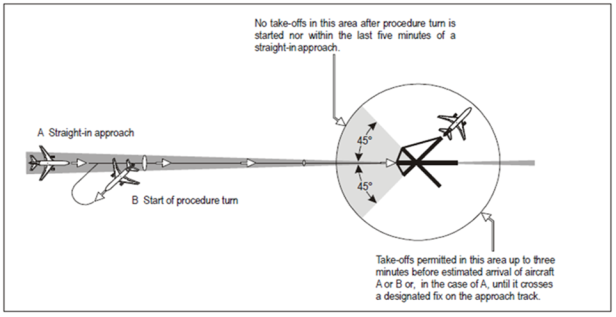
Figure 37: Separation of departing aircraft from arriving aircraft
(b) If an arriving aircraft is making a straight-in approach, a departing aircraft may take off:
(1) in any direction until 5 minutes before the arriving aircraft is estimated to be over the instrument runway;
(2) in a direction which is different by at least 45 degrees from the reciprocal of the direction of approach of the arriving aircraft:
(i) until 3 minutes before the arriving aircraft is estimated to be over the beginning of the instrument runway (see Figure 37); or
(ii) before the arriving aircraft crosses a designated fix on the approach track; the location of such fix should be determined by the air traffic services provider after consultation with the operators, and approved by the competent authority.
AMC1 ATS.TR.210(c)(2)(ii) Operation of air traffic control service
ED Decision 2020/008/R
PROCEDURAL CONTROL — LATERAL SEPARATION CRITERIA AND MINIMA
Lateral separation should be applied by one of the following means:
(a) By reference to the same or different geographic locations
By position reports which positively indicate that the aircraft are over different geographic locations as determined visually or by reference to a navigation aid (see Figure 38).
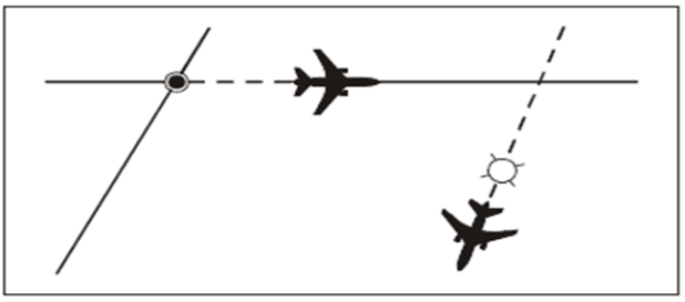
Figure 38: Using same or different geographic locations
(b) By use of NDB, VOR or GNSS on intersecting tracks or ATS routes
By requiring aircraft to fly on specified tracks which are separated by a minimum amount appropriate to the navigation aid employed. Lateral separation between two aircraft exists when:
(1) (VOR) both aircraft are established on radials diverging by at least 15 degrees and at least one aircraft is at a distance of 28 km (15 NM) or more from the facility (see Figure 39);

Figure 39: Separation using the same VOR
(2) (NDB) both aircraft are established on tracks to or from the NDB which are diverging by at least 30 degrees and at least one aircraft is at a distance of 28 km (15 NM) or more from the facility (see Figure 40);

Figure 40: Separation using the same NDB
(3) (GNSS/GNSS) each aircraft is confirmed to be established on a track with zero offset between two waypoints and at least one aircraft is at a minimum distance from a common point as specified in Table 1 below; or
(4) (VOR/GNSS) the aircraft using VOR is established on a radial to or from the VOR and the other aircraft using GNSS is confirmed to be established on a track with zero offset between two waypoints and at least one aircraft is at a minimum distance from a common point as specified in the table below.
|
|
Aircraft 1: VOR or GNSS Aircraft 2: GNSS |
|
|
Angular difference between tracks measured at the common point |
FL010-FL090 Distance from a common point |
FL200-FL600 Distance from a common point |
|
15-135 |
27.8 km (15 NM) |
43 km (23 NM) |
|
The distances in the table are ground distances. States must take into account the distance (slant range) from the source of a DME signal to the receiving antenna when DME is being utilised to provide range information. |
||
(c) By use of different navigation aids or methods
Lateral separation between aircraft using different navigation aids, or when one aircraft is using RNAV equipment, should be established by ensuring that the derived protected airspaces for the navigation aid(s) or RNP do not overlap.
(d) Lateral separation of aircraft on published instrument flight procedures for arrivals and departures
Lateral separation of departing and/or arriving aircraft, using instrument flight procedures, will exist where:
(1) the distance between any combination of RNAV 1 with RNAV 1, or RNP 1, RNP APCH or RNP AR APCH tracks is not less than 13 km (7 NM); or
(2) the distance between any combination of RNP 1, RNP APCH or RNP AR APCH tracks is not less than 9.3 km (5 NM); or
(3) the protected areas of tracks designed using obstacle clearance criteria do not overlap and provided operational error is considered.
(e) RNAV operations where RNP is specified on parallel tracks or ATS routes
Within designated airspace or on designated routes, where RNP is specified, lateral separation between RNAV-equipped aircraft may be obtained by requiring aircraft to be established on the centre lines of parallel tracks or ATS routes spaced at a distance which ensures that the protected airspace of the tracks or ATS routes does not overlap.
(f) Transitioning into airspace where a greater lateral separation minimum applies
Lateral separation will exist when aircraft are established on specified tracks which:
(1) are separated by an appropriate minimum; and
(2) diverge by at least 15 degrees until the applicable lateral separation minimum is established,
provided that it is possible to ensure, by means approved by the competent authority, that aircraft have the navigation capability necessary to ensure accurate track guidance.
GM1 to AMC1 ATS.TR.210(c)(2)(ii) Operation of air traffic control service
ED Decision 2020/008/R
PROCEDURAL CONTROL — LATERAL SEPARATION OF AIRCRAFT ON PUBLISHED INSTRUMENT FLIGHT PROCEDURES FOR ARRIVALS AND DEPARTURES
ICAO Circular 324 ‘Guidelines for Lateral Separation of Arriving and Departing Aircraft on Published Adjacent Instrument Flight Procedures’ contains information on separation of arrival and departure tracks using non-overlapping protected areas based on obstacle clearance criteria, as provided for in ICAO Doc 8168 ‘Procedures for Air Navigation Services — Aircraft Operations, Volume II — Construction of Visual and Instrument Flight Procedures’.
GM1 ATS.TR.210(c)(2)(ii) Operation of air traffic control service
ED Decision 2020/008/R
PROCEDURAL CONTROL — LATERAL SEPARATION APPLICATION
(a) Lateral separation should be applied so that the distance between those portions of the intended routes for which the aircraft are to be laterally separated is never less than an established distance to account for navigational inaccuracies plus a specified buffer. This buffer should be determined by the air traffic services provider and approved by the competent authority and included in the lateral separation minima as an integral part thereof.
(b) Lateral separation of aircraft is obtained by requiring operation on different routes or in different geographical locations as determined by visual observation, by the use of navigation aids or by the use of RNAV equipment.
(c) Where a route flown by an aircraft involves a specified turn which will result in the minimum lateral separation being infringed, another type of separation or another minimum shall be established prior to the aircraft commencing the turn (see Figures 41 and 42).
(d) For flyover waypoints, aircraft are required to first fly over the waypoint before executing the turn. After the turn, the aircraft may either navigate to join the route immediately after the turn or navigate to the next defined waypoint before rejoining the route. This will require additional lateral separation on the overflown side of the turn (See Figure 41).
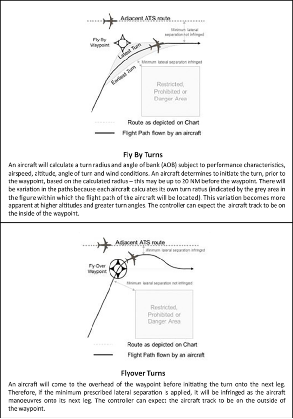
Figure 41: Turn over flyover waypoint and turn at fly-by waypoint
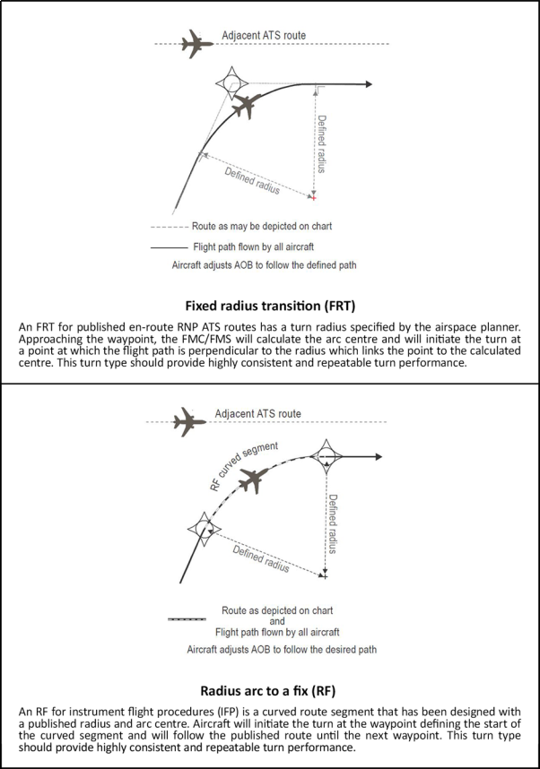
Figure 42: Fixed radius transition (FRT) and radius arc to a Fix (RF) turn
GM1 ATS.TR.210(d) Operation of air traffic control service
ED Decision 2020/008/R
APPLICATION OF SEPARATION MINIMA TO IDENTIFIED AIRCRAFT
(a) When the control of an identified aircraft is to be transferred to a control sector that will provide the aircraft with procedural separation, the transferring air traffic controller should ensure that appropriate procedural separation is established between that aircraft and any other controlled aircraft before the transfer is effected.
(b) When the control of an identified aircraft is to be transferred to a control sector that will provide the aircraft with procedural separation, such separation should be established by the transferring air traffic controller before the aircraft reaches the limits of the transferring air traffic controller’s area of responsibility, or before the aircraft leaves the relevant area of surveillance coverage.
ATS.TR.215 Selection and notification of separation minima for the application of point ATS.TR.210(c)
Commission Implementing Regulation (EU) 2020/469
(a) The selection of separation minima for application within a given portion of airspace shall be made by the air traffic services provider responsible for the provision of air traffic services and approved by the competent authority concerned.
(b) For traffic that will pass from one into the other of neighbouring airspaces and for routes that are closer to the common boundary of the neighbouring airspaces than the separation minima applicable in the circumstances, the selection of separation minima shall be made in consultation with the air traffic services providers responsible for the provision of air traffic services in neighbouring airspace.
(c) Details of the selected separation minima and of their areas of application shall be notified:
(1) to the air traffic services units concerned;
(2) to pilots and aircraft operators through aeronautical information publications, where separation is based on the use by aircraft of specified navigation aids or specified navigation techniques.
ATS.TR.220 Application of wake turbulence separation
Commission Implementing Regulation (EU) 2020/469
(a) Air traffic control units shall apply wake turbulence separation minima to aircraft in the approach and departure phases of flight in either of the following circumstances:
(1) an aircraft is operating directly behind another aircraft at the same altitude or less than 300 m (1 000 ft) below it;
(2) both aircraft are using the same runway, or parallel runways separated by less than 760 m (2 500 ft);
(3) an aircraft is crossing behind another aircraft, at the same altitude or less than 300 m (1 000 ft) below it.
(b) Paragraph (a) shall not apply to arriving VFR flights and to arriving IFR flights executing visual approach when the aircraft has reported the preceding aircraft in sight and has been instructed to follow and maintain own separation from that aircraft. In those cases, the air traffic control unit shall issue caution for wake turbulence.
AMC1 ATS.TR.220 Application of wake turbulence separation
ED Decision 2020/008/R
CATEGORISATION OF AIRCRAFT FOR THE PURPOSES OF WAKE TURBULENCE SEPARATION MINIMA APPLICATION
Wake turbulence separation minima should be based on a grouping of aircraft types into four categories according to the maximum certificated take-off mass as follows:
(a) SUPER (S) if so identified by the competent authority;
(b) HEAVY (H) — all aircraft types of 136 000 kg or more;
(c) MEDIUM (M) — aircraft types less than 136 000 kg but more than 7 000 kg; and
(d) LIGHT (L) — aircraft types of 7 000 kg or less.
GM1 to AMC1 ATS.TR.220 Application of wake turbulence separation
ED Decision 2020/008/R
For the Airbus A380-800 aircraft, with a maximum take-off mass in the order of 560 000 kg, it is recommended to apply an increase of the wake turbulence separation minima associated with the HEAVY category.
AMC2 ATS.TR.220 Application of wake turbulence separation
ED Decision 2020/008/R
TIME-BASED WAKE TURBULENCE LONGITUDINAL SEPARATION MINIMA — ARRIVING AIRCRAFT
Except for arriving VFR flights, and for arriving IFR flights executing visual approach, the following separation minima should be applied to aircraft landing behind a SUPER, a HEAVY or a MEDIUM aircraft:
(a) MEDIUM aircraft behind SUPER aircraft: 3 minutes;
(b) MEDIUM aircraft behind HEAVY aircraft: 2 minutes;
(c) LIGHT aircraft behind SUPER aircraft: 4 minutes; and
(d) LIGHT aircraft behind a HEAVY or MEDIUM aircraft: 3 minutes.
AMC3 ATS.TR.220 Application of wake turbulence separation
ED Decision 2020/008/R
TIME-BASED WAKE TURBULENCE LONGITUDINAL SEPARATION MINIMA — DEPARTING AIRCRAFT
(a) A separation minimum of 3 minutes should be applied for a LIGHT or MEDIUM aircraft and 2 minutes for a HEAVY aircraft taking off behind a SUPER aircraft when the aircraft are using:
(1) the same runway;
(2) parallel runways separated by less than 760 m (2 500 ft);
(3) crossing runways if the projected flight path of the second aircraft will cross the projected flight path of the first aircraft at the same altitude or less than 300 m (1 000 ft) below; and
(4) parallel runways separated by 760 m (2 500 ft) or more if the projected flight path of the second aircraft will cross the projected flight path of the first aircraft at the same altitude or less than 300 m (1 000 ft) below.
(b) A separation minimum of 4 minutes should be applied for a LIGHT or MEDIUM aircraft when taking off behind an SUPER aircraft from:
(1) an intermediate part of the same runway; or
(2) an intermediate part of a parallel runway separated by less than 760 m (2 500 ft).
(c) A separation minimum of 2 minutes should be applied between a LIGHT or MEDIUM aircraft taking off behind a HEAVY aircraft or a LIGHT aircraft taking off behind a MEDIUM aircraft when the aircraft are using:
(1) the same runway (see Figure 43);
(2) parallel runways separated by less than 760 m (2 500 ft) (see Figure 43);
(3) crossing runways if the projected flight path of the second aircraft will cross the projected flight path of the first aircraft at the same altitude or less than 300 m (1 000 ft) below (see Figure 44); and
(4) parallel runways separated by 760 m (2 500 ft) or more if the projected flight path of the second aircraft will cross the projected flight path of the first aircraft at the same altitude or less than 300 m (1 000 ft) below (see Figure 44).
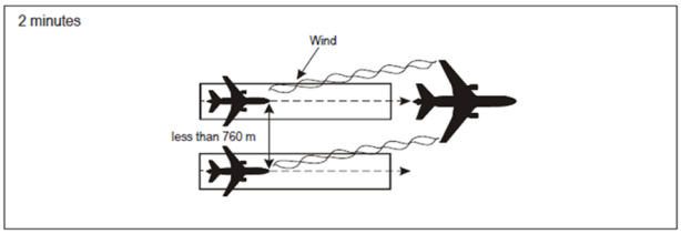
Figure 43: 2-minute separation for following aircraft
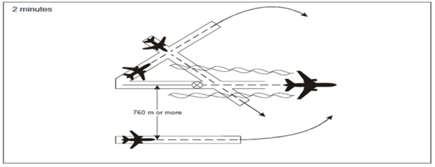
Figure 44: 2-minute wake turbulence separation for crossing aircraft
(d) A separation minimum of 3 minutes should be applied (see Figure 45) between a LIGHT or MEDIUM aircraft when taking off behind a HEAVY aircraft or a LIGHT aircraft when taking off behind a MEDIUM aircraft from:
(1) an intermediate part of the same runway; or
(2) an intermediate part of a parallel runway separated by less than 760 m (2 500 ft).
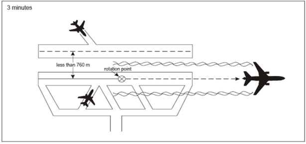
Figure 45: 3-minute wake turbulence separation for following aircraft
AMC4 ATS.TR.220 Application of wake turbulence separation
ED Decision 2020/008/R
TIME-BASED WAKE TURBULENCE LONGITUDINAL SEPARATION MINIMA — DISPLACED LANDING THRESHOLD
(a) A separation minimum of 3 minutes should be applied between a LIGHT or MEDIUM aircraft and a SUPER aircraft when operating on a runway with a displaced landing threshold when:
(1) a departing LIGHT or MEDIUM aircraft follows a SUPER aircraft arrival; or
(2) an arriving LIGHT or MEDIUM aircraft follows a SUPER aircraft departure,
if the projected flight paths are expected to cross.
(b) A separation minimum of 2 minutes should be applied between a LIGHT or MEDIUM aircraft and a HEAVY aircraft and between a LIGHT aircraft and a MEDIUM aircraft when operating on a runway with a displaced landing threshold when:
(1) a departing LIGHT or MEDIUM aircraft follows a HEAVY aircraft arrival and a departing LIGHT aircraft follows a MEDIUM aircraft arrival; or
(2) an arriving LIGHT or MEDIUM aircraft follows a HEAVY aircraft departure and an arriving LIGHT aircraft follows a MEDIUM aircraft departure,
if the projected flight paths are expected to cross.
AMC5 ATS.TR.220 Application of wake turbulence separation
ED Decision 2020/008/R
TIME-BASED WAKE TURBULENCE LONGITUDINAL SEPARATION MINIMA — OPPOSITE DIRECTION
(a) A separation minimum of 3 minutes should be applied between a LIGHT or MEDIUM aircraft and a SUPER aircraft when the SUPER aircraft is making a low or missed approach and the LIGHT or MEDIUM aircraft is:
(1) utilising an opposite-direction runway for take-off; or
(2) landing on the same runway in the opposite direction, or on a parallel opposite-direction runway separated by less than 760 m (2 500 ft).
(b) A separation minimum of 2 minutes should be applied between a LIGHT or MEDIUM aircraft and a HEAVY aircraft and between a LIGHT aircraft and a MEDIUM aircraft when the heavier aircraft is making a low or missed approach and the lighter aircraft is:
(1) utilising an opposite-direction runway for take-off (see Figure 46); or
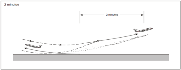
Figure 46: 2-minute wake turbulence separation for opposite-direction take-off
(2) landing on the same runway in the opposite direction, or on a parallel opposite-direction runway separated by less than 760 m (2 500 ft) (see Figure 47).
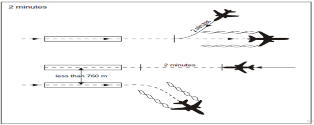
Figure 47: 2-minute wake turbulence separation for opposite-direction landing
AMC6 ATS.TR.220 Application of wake turbulence separation
ED Decision 2020/008/R
DISTANCE-BASED WAKE TURBULENCE SEPARATION MINIMA BASED ON ATS SURVEILLANCE SYSTEM
The following distance-based wake turbulence separation minima should be applied to aircraft being provided with an ATS surveillance service in the approach and departure phases:
|
PRECEDING AIRCRAFT |
SUCCEEDING AIRCRAFT |
WAKE TURBULENCE RADAR SEPARATION MINIMA |
|
SUPER or HEAVY |
SUPER |
Not required. In this case, separation reverts to radar separation minima as established by the air traffic services provider and approved by the competent authority. |
|
SUPER |
HEAVY |
11.1 km (6.0 NM) |
|
SUPER |
MEDIUM |
13.0 km (7.0 NM) |
|
SUPER |
LIGHT |
14.8 km (8.0 NM) |
|
HEAVY |
HEAVY |
7.4 km (4.0 NM) |
|
HEAVY |
MEDIUM |
9.3 km (5.0 NM) |
|
HEAVY |
LIGHT |
11.1 km (6.0 NM) |
|
MEDIUM |
LIGHT |
9.3 km (5 NM) |
GM1 to AMC6 ATS.TR.220 Application of wake turbulence separation
ED Decision 2020/008/R
Figures 48 and 49 illustrate the application of the separation minima between HEAVY, MEDIUM and LIGHT aircraft prescribed in AMC6 ATS.TR.220.
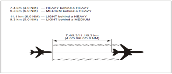
Figure 48: Operating directly behind
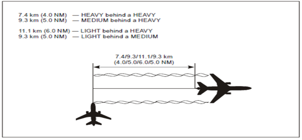 =
=
Figure 49: Crossing behind
AMC7 ATS.TR.220 Application of wake turbulence separation
ED Decision 2020/008/R
RECAT-EU WAKE TURBULENCE SEPARATION MINIMA
(a) As an alternative to the wake turbulence separation minima prescribed in AMC1 to AMC6 ATS.TR.220, an air traffic services provider may decide to implement RECAT-EU or parts thereof, subject to the approval of the competent authority.
(b) The following wake vortex aircraft groupings, based on the allocation of aircraft types to six categories according to both maximum certificated take-off mass and wingspan, and associated separation minima should be used when applying RECAT-EU:
(1) ‘SUPER HEAVY’ — all aircraft types of 100 000 kg or more, and a wingspan between 72 m and 80 m;
(2) ‘UPPER HEAVY’ — all aircraft types of 100 000 kg or more, and a wingspan between 60 m and 72 m;
(3) ‘LOWER HEAVY’ — all aircraft types of 100 000 kg or more, and a wingspan below 52 m;
(4) ‘UPPER MEDIUM’ — aircraft types less than 100 000 kg but more than 15 000 kg, and a wingspan above 32 m;
(5) ‘LOWER MEDIUM’ — aircraft types less than 100 000 kg but more than 15 000 kg, and a wingspan below 32 m;
(6) ‘LIGHT’ — all aircraft types of 15 000 kg or less (without wingspan criterion).
(c) Aircraft types with maximum certificated take-off mass of 100 000 kg or more, and wingspan between 52 m and 60 m are included in one of the above categories on the basis of specific analyses.
(d) RECAT-EU wake turbulence distance-based separation minima for arriving and departing aircraft when ATS surveillance service is provided should be:
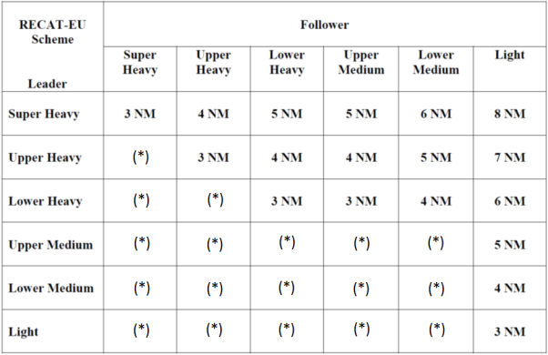
(*) means that the separation minimum to be applied is the horizontal separation minimum based on an ATS surveillance system (established in accordance with AMC1 ATS.TR.210(c)(2)), and should remain compatible with runway capacity.
(e) RECAT-EU wake turbulence time-based separation minima between departing aircraft should be:
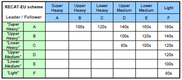
(f) Wake turbulence time-based separation minima between departing aircraft should be applied by determining airborne times between successive aircraft.
(g) An additional 60 seconds should be applied to all the wake turbulence time-based separation minima above when taking off from:
(1) an intermediate part of the same runway; or
(2) an intermediate part of a parallel runway separated by less than 760 m (2 500 ft).
GM1 to AMC7 ATS.TR.220 Application of wake turbulence separation
ED Decision 2020/008/R
APPLICATION OF RECAT-EU WAKE TURBULENCE SEPARATION SCHEME
(a) The implementation of RECAT-EU or parts thereof is considered to be a change to the air traffic services provider functional system and, as such, is supported by a safety assessment, in accordance with ATS.OR.205. Any such implementation should provide clear operational benefits.
(b) While the ICAO flight plan remains unchanged, the RECAT-EU wake vortex aircraft grouping should be displayed to air traffic controllers using the associated aircraft type information available in the flight data processing system.
(c) A list of aircraft types for each RECAT-EU aircraft grouping, in particular with respect to new aircraft types, is maintained by EASA and is available at https://www.easa.europa.eu/easa-and-you/air-traffic-management#group-easa-downloads.
GM1 ATS.TR.220 Application of wake turbulence separation
ED Decision 2020/008/R
WAKE TURBULENCE EFFECTS INDUCED BY HELICOPTERS
(a) Helicopters should be kept well clear of light aircraft when hovering or while air-taxiing.
(b) Helicopters produce vortices when in flight and there is some evidence that, per kilogramme of gross mass, their vortices are more intense than those of fixed-wing aircraft. When hovering in ground effect or air taxiing, helicopters generate downwash producing high-velocity outwash vortices to a distance approximately three times the diameter of the rotor.
ATS.TR.225 Responsibility for control
Commission Implementing Regulation (EU) 2020/469
(a) A controlled flight shall be under the control of only one air traffic control unit at any given time.
(b) Responsibility for the control of all aircraft operating within a given block of airspace shall be vested in a single air traffic control unit. However, control of an aircraft or groups of aircraft may be delegated to other air traffic control units provided that coordination between all air traffic control units concerned is assured.
ATS.TR.230 Transfer of responsibility for control
Commission Implementing Regulation (EU) 2020/469
(a) Place or time of transfer
The responsibility for the control of an aircraft shall be transferred from one air traffic control unit to another as follows:
(1) Between two units providing area control service
The responsibility for the control of an aircraft shall be transferred from a unit providing area control service in a control area to the unit providing area control service in an adjacent control area at the time of crossing the common control area boundary as estimated by the area control centre having control of the aircraft or at such other point or time as has been agreed between the two units.
(2) Between a unit providing area control service and a unit providing approach control service or between two units providing approach control service
The responsibility for the control of an aircraft shall be transferred from one unit to another, and vice versa, at a point or time agreed between the two units.
(3) Between a unit providing approach control service and an aerodrome control tower
(i) Arriving aircraft – The responsibility for the control of an arriving aircraft shall be transferred, as specified in letters of agreement and operation manuals, as appropriate, from the unit providing approach control service to the aerodrome control tower when the aircraft is in either of the following states:
(A) is in the vicinity of the aerodrome, and:
(a) it is considered that approach and landing will be completed in visual reference to the ground, or
(b) it has reached uninterrupted VMC;
(B) is at a prescribed point or level;
(C) has landed.
(ii) Departing aircraft – The responsibility for control of a departing aircraft shall be transferred, as specified in letters of agreement and operation manuals, as appropriate, from the aerodrome control tower to the unit providing approach control service:
(A) when VMC prevail in the vicinity of the aerodrome:
(a) prior to the time the aircraft leaves the vicinity of the aerodrome, or
(b) prior to the aircraft entering instrument meteorological conditions (IMC), or
(c) at a prescribed point or level;
(B) when IMC prevail at the aerodrome:
(a) immediately after the aircraft is airborne, or
(b) at a prescribed point or level.
(4) Between control sectors or positions within the same air traffic control unit
The responsibility for control of an aircraft shall be transferred from one control sector or position to another control sector or position within the same air traffic control unit at a point, level or time, as specified in air traffic services unit instructions.
(b) Coordination of transfer
(1) Responsibility for control of an aircraft shall not be transferred from one air traffic control unit to another without the consent of the accepting control unit, which shall be obtained in accordance with points (2), (3), (4) and (5).
(2) The transferring control unit shall communicate to the accepting control unit the appropriate parts of the current flight plan and any control information pertinent to the transfer requested.
(3) Where transfer of control is to be effected using ATS surveillance systems, the control information pertinent to the transfer shall include information regarding the position and, if required, the track and speed of the aircraft, as observed by ATS surveillance systems immediately prior to the transfer.
(4) Where transfer of control is to be effected using ADS-C data, the control information pertinent to the transfer shall include the four-dimensional position and other information as necessary.
(5) The accepting control unit shall:
(i) indicate its ability to accept control of the aircraft on the terms specified by the transferring control unit, unless by prior agreement between the two units concerned the absence of any such indication is understood to signify acceptance of the terms specified, or indicate any necessary changes thereto;
(ii) specify any other information or clearance for a subsequent portion of the flight, which it requires the aircraft to have at the time of transfer.
(6) Unless otherwise specified by an agreement between the two control units concerned, the accepting control unit shall not notify the transferring control unit when it has established two-way voice or data link communications, or both, with and assumed control of the aircraft concerned.
(7) Standardised phraseology shall be used in the coordination between air traffic services units or sectors, or both. Only when standardised phraseology cannot serve an intended transmission, plain language shall be used.
AMC1 ATS.TR.230 Transfer of responsibility for control
ED Decision 2020/008/R
COORDINATION IN RESPECT OF THE AIR TRAFFIC CONTROL SERVICE PROVISION — GENERAL
Agreements between air traffic control units or sectors and local instructions concerning coordination and transfer of control of flights should cover the following, as applicable:
(a) definition of areas of responsibility and common interest, airspace structure and airspace classification(s);
(b) any delegation of responsibility for the provision of air traffic services;
(c) procedures for the exchange of flight plan and control data, including use of automated and/or verbal coordination messages;
(d) means of communication;
(e) requirements and procedures for approval requests;
(f) significant points, levels or times for transfer of control;
(g) significant points, levels or times for transfer of communication;
(h) conditions applicable to the transfer and acceptance of control, such as specified altitudes/flight levels, specific separation minima or spacing to be established at the time of transfer, and the use of automation;
(i) ATS surveillance system coordination procedures;
(j) SSR code assignment procedures;
(k) procedures for departing traffic;
(l) designated holding fixes and procedures for arriving traffic;
(m) applicable contingency procedures; and
(n) any other provisions or information relevant to the coordination and transfer of control of flights.
GM1 ATS.TR.230 Transfer of responsibility for control
ED Decision 2020/008/R
COORDINATION IN RESPECT OF THE AIR TRAFFIC CONTROL SERVICE PROVISION — GENERAL
(a) The coordination and transfer of control of a flight between successive air traffic control units and control sectors should be effected by a dialogue comprising the following stages:
(1) notification of the flight in order to prepare for coordination, as necessary;
(2) coordination of conditions of transfer of control by the transferring air traffic control unit;
(3) coordination, if necessary, and acceptance of conditions of transfer of control by the accepting control unit; and
(4) transfer of control to the accepting control unit or control sector.
(b) Air traffic control units should, to the extent possible, establish and apply standardised procedures for the coordination and transfer of control of flights, in order, inter alia, to reduce the need for verbal coordination. Such coordination procedures should be specified in letters of agreement and local instructions, as applicable.
GM2 ATS.TR.230 Transfer of responsibility for control
ED Decision 2020/008/R
LETTERS OF AGREEMENT AND OPERATION MANUALS
Relevant information contained in letters of agreement should be included in the operation manual of the air traffic services units concerned.
AMC1 ATS.TR.230(a) Transfer of responsibility for control
ED Decision 2020/008/R
COORDINATION BETWEEN AIR TRAFFIC CONTROL UNITS PROVIDING AIR TRAFFIC SERVICE WITHIN CONTIGUOUS CONTROL AREAS — TRANSFER OF CONTROL
(a) The responsibility for the control of an aircraft should be transferred from the air traffic control unit to the next unit at the time of crossing the common control area boundary as determined by the unit having control of the aircraft or at such other point or time as has been agreed between the two units.
(b) Where specified in letters of agreement between the air traffic control units concerned, and when transferring an aircraft, the transferring unit should notify the accepting control unit that the aircraft is in position to be transferred, and specify that the responsibility for control should be assumed by the accepting control unit forthwith at the time of crossing the control boundary or other transfer control point specified in letters of agreement between the air traffic control units or at such other point or time coordinated between the two units.
(c) If the transfer of control time or point is other than forthwith, the accepting control unit should not alter the clearance of the aircraft prior to the agreed transfer of control time or point without the approval of the transferring unit.
(d) If transfer of communication is used to transfer an aircraft to an accepting control unit, responsibility for control should not be assumed until the time of crossing the control area boundary or other transfer of control point specified in letters of agreement between the air traffic control units.
GM1 ATS.TR.230(a)(2) Transfer of responsibility for control
ED Decision 2020/008/R
DIVISION OF CONTROL BETWEEN A UNIT PROVIDING AREA CONTROL SERVICE AND A UNIT PROVIDING APPROACH CONTROL SERVICE
(a) Except when otherwise specified in letters of agreement or local instructions, or by the ACC concerned in individual cases, a unit providing approach control service may issue clearances to any aircraft released to it by an ACC without reference to the ACC. However, when an approach has been missed, the ACC should, if affected by the missed approach, be advised immediately and subsequent action should be coordinated between the ACC and the unit providing approach control service as necessary.
(b) An ACC may, after coordination with the unit providing approach control service, release aircraft directly to aerodrome control towers if the entire approach will be made under VMC.
GM1 ATS.TR.230(a)(3) Transfer of responsibility for control
ED Decision 2020/008/R
DIVISION OF CONTROL BETWEEN A UNIT PROVIDING APPROACH CONTROL SERVICE AND A UNIT PROVIDING AERODROME CONTROL SERVICE
(a) A unit providing approach control service should retain control of arriving aircraft until such aircraft have been transferred to the aerodrome control tower and are in communication with the aerodrome control tower. Letters of agreement or local instructions, appropriate to the airspace structure, terrain, meteorological conditions and air traffic services facilities available, should establish rules for the transfer of arriving aircraft.
(b) A unit providing approach control service may authorise an aerodrome control tower to release an aircraft for take-off subject to the discretion of the aerodrome control tower with respect to arriving aircraft.
(c) Aerodrome control towers should, when so prescribed in letters of agreement or local instructions, obtain approval from the unit providing approach control service prior to authorising operation of special VFR flights.
GM2 ATS.TR.230(a)(3) Transfer of responsibility for control
ED Decision 2020/008/R
TRANSFER OF FLIGHTS BETWEEN ACC AND AERODROME CONTROL TOWER
Even though there is an approach control unit, control of certain flights may be transferred directly from an ACC to an aerodrome control tower and vice versa, subject to prior arrangement between the units concerned for the relevant part of approach control service to be provided by the ACC or the aerodrome control tower, as applicable.
GM1 ATS.TR.230(a)(3)(i) Transfer of responsibility for control
ED Decision 2020/008/R
COORDINATION OF STANDARD CLEARANCES FOR ARRIVING AIRCRAFT
(a) Wherever possible, the air traffic services providers concerned should establish standardised procedures for transfer of control between the air traffic control units concerned and standard clearances for arriving aircraft.
(b) Where standard clearances for arriving aircraft are in use and, provided no terminal delay is expected, clearance to follow the appropriate standard instrumental arrival (STAR) will normally be issued by the ACC without prior coordination with or approval from the approach control unit or the aerodrome control tower, as applicable.
(c) Prior coordination of clearances should be required only in the event that a variation to the standard clearance or the standardised transfer of control procedures is necessary or desirable for operational reasons.
(d) Provision should be made to:
(1) ensure that the approach control unit is at all times kept informed of the sequence of aircraft following the same STAR; and
(2) display the designators of assigned STARs to the ACC, the approach control unit and/or the aerodrome control tower, as applicable.
GM1 ATS.TR.230(a)(3)(ii) Transfer of responsibility for control
ED Decision 2020/008/R
COORDINATION OF STANDARD CLEARANCES FOR DEPARTING AIRCRAFT
(a) Wherever possible, the air traffic services providers concerned should establish standardised procedures for transfer of control between the air traffic control units concerned and standard clearances for departing aircraft.
(b) Where standard clearances for departing aircraft have been agreed to between the units concerned, the aerodrome control tower will normally issue the appropriate standard clearance without prior coordination with or approval from the approach control unit or ACC.
(c) Prior coordination of clearances should be required only in the event that a variation to the standard clearance or the standardised transfer of control procedures is necessary or desirable for operational reasons; for example, in the case of a change on the cleared initial flight level.
(d) Provision should be made to:
(1) ensure that the approach control unit at all times is kept informed of the sequence in which aircraft will depart as well as the runway to be used; and
(2) display the designators of assigned standard instrumental departures (SIDs) to the aerodrome control tower, the approach control unit and/or the ACC as applicable.
AMC1 ATS.TR.230(a)(4) Transfer of responsibility for control
ED Decision 2020/008/R
COORDINATION BETWEEN CONTROL POSITIONS WITHIN THE SAME UNIT
Appropriate flight plan and control information should be exchanged between control positions within the same air traffic control unit, in respect of:
(a) all aircraft for which responsibility for control will be transferred from one control position to another;
(b) aircraft operating in such close proximity to the boundary between control sectors that control of traffic within an adjacent sector may be affected;
(c) all aircraft for which responsibility for control has been delegated by an air traffic controller using procedural methods to an air traffic controller using an ATS surveillance system, as well as other aircraft affected.
AMC1 ATS.TR.230(b)(2) Transfer of responsibility for control
ED Decision 2020/008/R
COORDINATION BETWEEN AIR TRAFFIC CONTROL UNITS PROVIDING AIR TRAFFIC SERVICES WITHIN CONTIGUOUS CONTROL AREAS — GENERAL
(a) Air traffic control units should forward from unit to unit, as the flight progresses, necessary flight plans and control information. When so required by agreement between air traffic services providers concerned, flight plans and flight progress information for flights along specified routes or portions of routes in close proximity to flight information region (FIR) boundaries should also be provided to the air traffic control units in charge of the FIRs adjacent to such routes or portions of routes.
(b) The flight plan and control information in point (b) of ATS.TR.230 should be transmitted in sufficient time to permit reception and analysis of the data by the receiving unit(s) and necessary coordination between the units concerned.
AMC2 ATS.TR.230(b)(2) Transfer of responsibility for control
ED Decision 2020/008/R
EXCHANGE OF MOVEMENT AND CONTROL DATA BETWEEN A UNIT PROVIDING AREA CONTROL SERVICE AND A UNIT PROVIDING APPROACH CONTROL SERVICE
(a) The unit providing approach control service should keep the ACC promptly advised of pertinent data on controlled traffic.
(b) The ACC should keep the unit providing approach control service promptly advised of pertinent data on controlled traffic.
(c) The ACC should normally forward to the unit providing approach control service information on arriving aircraft not less than 15 minutes before the estimated time of arrival and should revise such information as necessary
GM1 to AMC2 ATS.TR.230(b)(2) Transfer of responsibility for control
ED Decision 2020/008/R
EXCHANGE OF MOVEMENT AND CONTROL DATA FROM A UNIT PROVIDING APPROACH CONTROL SERVICE TO A UNIT PROVIDING AREA CONTROL SERVICE
Pertinent data on controlled traffic should include:
(a) runway(s)-in-use and expected type of instrument approach procedure;
(b) lowest vacant level at the holding fix available for use by the ACC;
(c) average time interval or distance between successive arrivals as determined by the unit providing approach control service;
(d) revision of the expected approach time issued by the ACC when the calculation of the expected approach time by the unit providing approach control service indicates a variation of 5 minutes or such other time as has been agreed between the two air traffic control units concerned;
(e) arrival times over the holding fix when these vary by 3 minutes, or such other time as has been agreed between the two air traffic control units concerned, from those previously estimated;
(f) cancellations by aircraft of IFR flight if these will affect levels at the holding fix or expected approach times of other aircraft;
(g) aircraft departure times or, if agreed between the two air traffic control units concerned, the estimated time at the control area boundary or other specified point;
(h) all available information relating to overdue or unreported aircraft; and
(i) missed approaches which may affect the ACC.
GM2 to AMC2 ATS.TR.230(b)(2) Transfer of responsibility for control
ED Decision 2020/008/R
EXCHANGE OF MOVEMENT AND CONTROL DATA FROM A UNIT PROVIDING AREA CONTROL SERVICE TO A UNIT PROVIDING APPROACH CONTROL SERVICE
Pertinent data on controlled traffic should include:
(a) identification, type and point of departure of arriving aircraft;
(b) estimated time and proposed level of arriving aircraft over holding fix or other specified point;
(c) actual time and proposed level of arriving aircraft over holding fix if the aircraft is released to the unit providing approach control service after arrival over the holding fix;
(d) requested type of IFR approach procedure if different from that specified by the approach control unit;
(e) expected approach time issued;
(f) when required, statement that an aircraft has been instructed to contact the unit providing approach control service;
(g) when required, statement that an aircraft has been released to the unit providing approach control service including, if necessary, the time and conditions of release; and
(h) anticipated delay to departing traffic due to congestion.
AMC3 ATS.TR.230(b)(2) Transfer of responsibility for control
ED Decision 2020/008/R
EXCHANGE OF MOVEMENT AND CONTROL DATA BETWEEN A UNIT PROVIDING APPROACH CONTROL SERVICE AND A UNIT PROVIDING AERODROME CONTROL SERVICE
(a) An aerodrome control tower should keep the unit providing approach control service promptly advised of pertinent data on relevant controlled traffic.
(b) The unit providing approach control service should keep the aerodrome control tower promptly advised of pertinent data on controlled traffic.
GM1 to AMC3 ATS.TR.230(b)(2) Transfer of responsibility for control
ED Decision 2020/008/R
EXCHANGE OF MOVEMENT AND CONTROL DATA FROM AN AERODROME CONTROL TOWER TO A UNIT PROVIDING APPROACH CONTROL SERVICE
Pertinent data on controlled traffic should include:
(a) arrival and departure times;
(b) when required, statement that the first aircraft in an approach sequence is in communication with and is sighted by the aerodrome control tower, and that reasonable assurance exists that a landing can be accomplished;
(c) all available information relating to overdue or unreported aircraft;
(d) information concerning missed approaches; and
(e) information concerning aircraft that constitute essential local traffic to aircraft under the control of the unit providing approach control service.
GM2 to AMC3 ATS.TR.230(b)(2) Transfer of responsibility for control
ED Decision 2020/008/R
EXCHANGE OF MOVEMENT AND CONTROL DATA FROM A UNIT PROVIDING APPROACH CONTROL SERVICE TO AN AERODROME CONTROL TOWER
Pertinent data on controlled traffic should include:
(a) estimated time and proposed level of arriving aircraft over the aerodrome, at least 15 minutes prior to estimated arrival;
(b) when required, a statement that an aircraft has been instructed to contact the aerodrome control tower and that control shall be assumed by that unit; and
(c) anticipated delay to departing traffic due to congestion
GM1 ATS.TR.230(b)(2) Transfer of responsibility for control
ED Decision 2020/008/R
COORDINATION BETWEEN AIR TRAFFIC CONTROL UNITS FOR APPROVAL REQUESTS
(a) If the flying time from the departure aerodrome of an aircraft to the boundary of an adjacent control area is less than the specified minimum required to permit transmission of the necessary flight plan and control information to the accepting control unit after take-off and to allow adequate time for reception, analysis and coordination, the transferring control unit should, prior to departure, forward that information to the accepting control unit together with a request for approval. The required time period should be specified in letters of agreement or local instructions, as appropriate. In the case of revisions to a previously transmitted current flight plan, and control data being transmitted earlier than this specified time period, no approval from the accepting control unit should be required.
(b) In the case of an aircraft in flight requiring an initial clearance when the flying time to the boundary of an adjacent control area is less than a specified minimum, the aircraft should be held within the transferring air traffic control unit’s control area until the flight plan and control information have been forwarded together with a request for approval, and coordination effected with the adjacent air traffic control unit.
(c) In the case of an aircraft requesting a change in its current flight plan, or of a transferring air traffic control unit proposing to change the current flight plan of an aircraft, and the flying time of the aircraft to the control area boundary is less than a specified minimum, the revised clearance should be withheld pending approval of the proposal by the adjacent air traffic control unit.
(d) When boundary estimate data is to be transmitted for approval by the accepting control unit, the time in respect of an aircraft not yet departed should be based on the estimated time of departure as determined by the air traffic control unit in whose area of responsibility the departure aerodrome is located. In respect of an aircraft in flight requiring an initial clearance, the time should be based on the estimated elapsed time from the holding fix to the boundary plus the time expected to be needed for coordination.
GM2 ATS.TR.230(b)(2) Transfer of responsibility for control
ED Decision 2020/008/R
COORDINATION BETWEEN AIR TRAFFIC CONTROL UNITS FOR TAKE-OFF AND CLEARANCE EXPIRY TIMES
(a) The take-off time should be specified by the ACC when it is necessary to:
(1) coordinate the departure with traffic not released to the unit providing approach control service; and
(2) provide en-route separation between departing aircraft following the same track.
(b) If the take-off time is not specified, the unit providing approach control service should determine it when necessary to coordinate the departure with traffic released to it.
(c) A clearance expiry time should be specified by the ACC if a delayed departure would conflict with traffic not released to the unit providing approach control service. If, for traffic reasons of its own, a unit providing approach control service has to specify in addition its own clearance expiry time, this should not be later than that specified by the ACC.
GM3 ATS.TR.230(b)(2) Transfer of responsibility for control
ED Decision 2020/008/R
COORDINATION BETWEEN AIR TRAFFIC SERVICES UNITS FOR CHANGE FROM IFR TO VFR
An air traffic control unit receiving notification of an aircraft’s intention to change from IFR to VFR flight should, as soon as practicable thereafter, so inform all other air traffic services units to whom the IFR flight plan was addressed, except those units through whose regions or areas the flight has already passed.
AMC1 ATS.TR.230(b)(7) Transfer of responsibility for control
ED Decision 2020/008/R
PHRASEOLOGIES TO BE USED IN THE COORDINATION BETWEEN AIR TRAFFIC SERVICES UNITS
(a) When, in accordance with ATS.TR.120, communications between air traffic services units or sectors are effected in English language, the following phraseology should be used for the coordination:
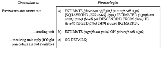
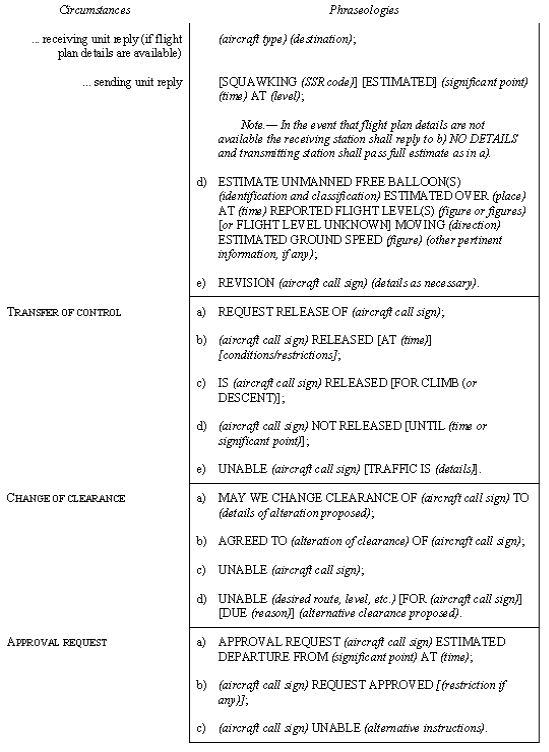
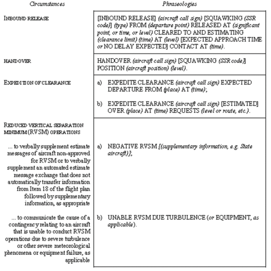
(b) When, in accordance with ATS.TR.120, communications between air traffic services units or sectors are effected in a mutually agreed language other than English, the air traffic services provider(s) should coordinate to develop and use a phraseology for coordination between such units or sectors.
Commission Implementing Regulation (EU) 2020/469
(a) ATC clearances shall be based solely on the requirements for providing air traffic control service.
(1) Clearances shall be issued solely for expediting and separating air traffic and be based on known traffic conditions which affect safety in aircraft operation. Such traffic conditions include not only aircraft in the air and on the manoeuvring area over which control is being exercised, but also any vehicular traffic or other obstructions not permanently installed on the manoeuvring area in use.
(2) Air traffic control units shall issue such ATC clearances as necessary to prevent collisions and to expedite and maintain an orderly flow of air traffic.
(3) ATC clearances shall be issued early enough to ensure that they are transmitted to the aircraft in sufficient time for it to comply with them.
(4) When the pilot-in-command of an aircraft informs an air traffic control unit that an ATC clearance is not satisfactory, the air traffic control unit shall issue an amended clearance, if practicable.
(5) When vectoring or assigning a direct routing not included in the flight plan, which takes an IFR flight off published ATS route or instrument procedure, an air traffic controller providing ATS surveillance service shall issue clearances such that the prescribed obstacle clearance exists at all times until the aircraft reaches the point where the pilot re-joins the flight plan route, or joins a published ATS route or instrument procedure.
(b) Contents of clearances
An ATC clearance shall indicate:
(1) aircraft identification as shown in the flight plan;
(2) clearance limit;
(3) route of flight:
(i) the route of flight shall be detailed in each clearance when deemed necessary;
(ii) the phrase ‘cleared flight planned route’ shall not be used when granting a re-clearance;
(4) level or levels of flight for the entire route or part thereof and changes of levels if required;
(5) any necessary instructions or information on other matters, such as ATFM departure slot if applicable, approach or departure manoeuvres, communications and the time of expiry of the clearance.
(c) In order to facilitate the delivery of the elements in point (b), an air traffic services provider shall assess the necessity for establishing standard departure and arrival routes and associated procedures to facilitate the:
(1) safe, orderly and expeditious flow of air traffic;
(2) description of the route and procedure in ATC clearances.
(d) Clearances for transonic flight
(1) The ATC clearance relating to the transonic acceleration phase of a supersonic flight shall extend at least to the end of that phase.
(2) The ATC clearance relating to the deceleration and descent of an aircraft from supersonic cruise to subsonic flight shall seek to provide for uninterrupted descent, at least during the transonic phase.
(e) Changes in clearance regarding route or level
(1) When issuing a clearance covering a requested change in route or level, the exact nature of the change shall be included in the clearance.
(2) When traffic conditions will not permit clearance of a requested change, the word ‘UNABLE’ shall be used. When warranted by circumstances, an alternative route or level shall be offered.
(f) Conditional clearances
Conditional phrases, such as ‘behind landing aircraft’ or ‘after departing aircraft’, shall not be used for movements affecting the active runway or runways except when the aircraft or vehicles concerned are seen by the appropriate air traffic controller and pilot. The aircraft or vehicle causing the condition in the clearance issued shall be the first aircraft or vehicle to pass in front of the other aircraft concerned. In all cases, a conditional clearance shall be given in the following order and consist of:
(1) the call sign;
(2) the condition;
(3) the clearance;
(4) a brief reiteration of the condition.
(g) Read-back of clearances, instructions and safety-related information
(1) The air traffic controller shall listen to the read-back concerning safety-related parts of ATC clearances and instructions as specified in points SERA.8015(e)(1) and (2) of the Annex to Implementing Regulation (EU) No 923/2012, to ascertain that the clearance or instruction, or both, have been correctly acknowledged by the flight crew and shall take immediate action to correct any discrepancies revealed by the read-back.
(2) Voice read-back of CPDLC messages shall not be required unless otherwise specified by the air traffic services provider.
(h) Coordination of clearances
An ATC clearance shall be coordinated between air traffic control units to cover the entire route of an aircraft or a specified portion thereof as follows.
(1) An aircraft shall be cleared for the entire route to the aerodrome of first intended landing in either of the following situations:
(i) when it has been possible, prior to departure, to coordinate the clearance between all the units under whose control the aircraft will come;
(ii) when there is reasonable assurance that prior coordination will be effected between those units under whose control the aircraft will subsequently come.
(2) When coordination as in point (1) has not been achieved or is not anticipated, the aircraft shall be cleared only to that point where coordination is reasonably assured; prior to reaching such point, or at such point, the aircraft shall receive further clearance, holding instructions being issued as appropriate.
(3) When prescribed by the air traffic services unit, aircraft shall contact a downstream air traffic control unit, for the purpose of receiving a downstream clearance prior to the transfer of control point.
(i) Aircraft shall maintain the necessary two-way communication with the current air traffic control unit whilst obtaining a downstream clearance.
(ii) A clearance issued as a downstream clearance shall be clearly identifiable as such to the pilot.
(iii) Unless coordinated, downstream clearances shall not affect the aircraft’s original flight profile in any airspace, other than that of the air traffic control unit responsible for the delivery of the downstream clearance.
(4) When an aircraft intends to depart from an aerodrome within a control area to enter another control area within a period of 30 minutes, or such other specific period of time as has been agreed between the area control centres concerned, coordination with the subsequent area control centre shall be effected prior to issuance of the departure clearance.
(5) When an aircraft intends to leave a control area for flight outside controlled airspace, and will subsequently re-enter the same or another control area, a clearance from the point of departure to the aerodrome of first intended landing may be issued. Such clearance or revisions thereto shall apply only to those portions of the flight conducted within controlled airspace.
ED Decision 2020/008/R
The issuance of ATC clearances by air traffic control units constitutes authority for an aircraft to proceed only in so far as known air traffic is concerned. ATC clearances do not constitute authority to violate any applicable regulations for promoting the safety of flight operations or for any other purpose; neither do clearances relieve a pilot-in-command of any responsibility whatsoever in connection with a possible violation of applicable rules and regulations.
GM1 ATS.TR.235(a)(5) ATC clearances
ED Decision 2020/008/R
ASSURANCE OF OBSTACLE CLEARANCE IN VECTORING
(a) Prescribed obstacle clearance will exist at all times when an air traffic controller issues clearances at or above the established minimum flight altitudes.
(b) When an IFR flight is being vectored, the pilot may be unable to determine the aircraft’s exact position in respect of obstacles in this area and consequently the altitude which provides the required obstacle clearance.
AMC1 ATS.TR.235(b) ATC clearances
ED Decision 2020/008/R
CONTENTS OF CLEARANCES FOR DEPARTING AIRCRAFT
Clearances for departing aircraft should specify, when necessary for the separation of aircraft:
(a) direction of take-off and turn after take-off;
(b) heading or track to be made good before taking up the cleared departure track;
(c) level to maintain before continuing climb to assigned level;
(d) time, point and/or rate at which a level change shall be made; and
(e) any other necessary manoeuvre consistent with safe operation of the aircraft.
GM1 to AMC1 ATS.TR.235(b) ATC clearances
ED Decision 2020/008/R
CORRECTION TO HEADING OR TRACK PRIOR TO TAKING UP THE CLEARED DEPARTURE TRACK
‘Track to be made good’ means that the pilot should correct for the wind effect and to fly a heading that would ensure keeping that track.
AMC2 ATS.TR.235(b) ATC clearances
ED Decision 2020/008/R
CONTENTS OF STANDARD CLEARANCES FOR DEPARTING AIRCRAFT
Standard clearances for departing aircraft should contain the following items:
(a) aircraft identification;
(b) clearance limit (normally destination aerodrome);
(c) designator of the assigned SID, if applicable;
(d) cleared level;
(e) allocated SSR code; and
(f) any other necessary instructions or information not contained in the SID description, e.g. instructions relating to change of frequency.
GM1 to AMC2 ATS.TR.235(b) ATC clearances
ED Decision 2020/008/R
CONTENTS OF STANDARD CLEARANCES FOR DEPARTING AIRCRAFT — COMMUNICATION FAILURE
(a) Clearances for departing aircraft may specify a cleared level other than that indicated in the filed flight plan for the en-route phase of flight, without a time or geographical limit for the cleared level. Such clearances will normally be used to facilitate the application of tactical control methods by air traffic control units, normally through the use of an ATS surveillance system.
(b) Where clearances for departing aircraft which contain no time or geographical limit for a cleared level are utilised, the action to be taken by an aircraft experiencing air-ground communication failure in the event that the aircraft has been radar-vectored away from the route specified in its current flight plan, should be prescribed on the basis of a regional air navigation agreement and included in the SID description or published in AIPs.
AMC3 ATS.TR.235(b) ATC clearances
ED Decision 2020/008/R
CLEARANCES FOR ARRIVING IFR FLIGHTS
An IFR flight should neither be cleared for an initial approach below the appropriate minimum altitude as specified by the State concerned nor descend below that altitude unless:
(a) the pilot has reported passing an appropriate point defined by a navigation aid or as a waypoint; or
(b) the pilot reports that the aerodrome is and can be maintained in sight; or
(c) the aircraft is conducting a visual approach; or
(d) the air traffic controller has determined the aircraft’s position through the use of an ATS surveillance system, and a lower minimum altitude has been specified for use when providing ATS surveillance services.
AMC4 ATS.TR.235(b) ATC clearances
ED Decision 2020/008/R
CONTENTS OF STANDARD CLEARANCES FOR ARRIVING AIRCRAFT
Standard clearances for arriving aircraft should contain the following items:
(a) aircraft identification;
(b) designator of the assigned STAR if applicable;
(c) runway-in-use, except when part of the STAR description;
(d) cleared level; and
(e) any other necessary instructions or information not contained in the STAR description, e.g. change of communications.
AMC1 ATS.TR.235(b)(2) ATC clearances
ED Decision 2020/008/R
SPECIFICATION OF CLEARANCE LIMIT
A clearance limit should be described by specifying the name of an appropriate significant point, or aerodrome, or controlled airspace boundary.
GM1 to AMC1 ATS.TR.235(b)(2) ATC clearances
ED Decision 2020/008/R
SPECIFICATION OF CLEARANCE LIMIT
(a) When prior coordination has been effected with units under whose control the aircraft will subsequently come, or if there is reasonable assurance that it can be effected a reasonable time prior to their assumption of control, the clearance limit should be the destination aerodrome or, if not practicable, an appropriate intermediate point, and coordination should be expedited so that a clearance to the destination aerodrome may be issued as soon as possible.
(b) If an aircraft has been cleared to an intermediate point in adjacent controlled airspace, the appropriate air traffic control unit will then be responsible for issuing, as soon as practicable, an amended clearance to the destination aerodrome.
(c) When the destination aerodrome is outside controlled airspace, the air traffic control unit responsible for the last controlled airspace through which an aircraft will pass should issue the appropriate clearance for flight to the limit of that controlled airspace.
GM1 ATS.TR.235(b)(3)(i) ATC clearances
ED Decision 2020/008/R
The phrase ‘cleared flight planned route’ may be used to describe any route or portion thereof, provided the route or portion thereof is identical to that filed in the flight plan and sufficient routing details are given to definitely establish the aircraft on its route. The phrases ‘cleared (designation) departure’ or ‘cleared (designation) arrival’ may be used when standard departure or arrival routes have been established and published in AIPs.
AMC1 ATS.TR.235(b)(4) ATC clearances
ED Decision 2020/008/R
INSTRUCTIONS IN CLEARANCES RELATING TO LEVELS
Instructions included in clearances relating to levels should consist of:
(a) cruising level(s) or, for cruise climb, a range of levels, and, if necessary, the point to which the clearance is valid with regard to the level(s);
(b) levels at which specified significant points are to be crossed, when necessary;
(c) the place or time for starting climb or descent, when necessary;
(d) the rate of climb or descent, when necessary; and
(e) detailed instructions concerning departure or approach levels, when necessary.
GM1 ATS.TR.235(b)(4) ATC clearances
ED Decision 2020/008/R
ASSIGNMENT OF FLIGHT LEVELS FOR CONTROLLED FLIGHTS
(a) Except when traffic conditions and coordination procedures permit authorisation of cruise climb, an air traffic control unit should normally authorise only one level for an aircraft beyond its control area, i.e. that level at which the aircraft will enter the next control area whether contiguous or not. It is the responsibility of the accepting control unit to issue clearance for further climb as appropriate. When relevant, aircraft will be advised to request en-route any cruising level changes desired.
(b) In so far as practicable, cruising levels of aircraft flying to the same destination should be assigned in a manner that will be correct for an approach sequence at destination.
(c) An aircraft at a cruising level should normally have priority over other aircraft requesting that cruising level. When two or more aircraft are at the same cruising level, the preceding aircraft should normally have priority.
GM1 ATS.TR.235(b)(5) ATC clearances
ED Decision 2020/008/R
CONTENT OF THE CLEARANCES — TIME OF EXPIRY
The time of expiry of the clearance indicates the time after which the clearance will be automatically cancelled if the flight has not been commenced.
GM1 ATS.TR.235(c) ATC clearances
ED Decision 2020/008/R
ESTABLISHMENT AND PROCEDURES FOR STANDARD ARRIVAL AND DEPARTURE ROUTES
Guidance related to the establishment of standard departure and arrival routes and associated procedures is available in ICAO Doc 9426 ‘ATS Planning Manual’ (Chapter 4, Appendix A).
AMC1 ATS.TR.235(d) ATC clearances
ED Decision 2020/008/R
CLEARANCES FOR TRANSONIC FLIGHT
(a) Air traffic control units should, whenever practicable, deliver clearance for the transonic acceleration phase to aircraft intending supersonic flight prior to departure.
(b) During the transonic and supersonic phases of a flight, amendments to the clearance should be kept to a minimum and should take due account of the operational limitations of the aircraft in these flight phases.
GM1 ATS.TR.235(e) ATC clearances
ED Decision 2020/008/R
CHANGE IN CLEARANCE REGARDING ROUTE
The nature of the change should include a description of the route and levels to the point where it joins the previously cleared route, or, if the aircraft will not rejoin the previous route, to the destination.
GM2 ATS.TR.235(e) ATC clearances
ED Decision 2020/008/R
CHANGE IN CLEARANCE REGARDING CRUISING LEVEL
If it is necessary to change the cruising level of an aircraft operating along an established ATS route extending partly within and partly outside controlled airspace and where the respective series of cruising levels are not identical, the change should, whenever possible, be effected within controlled airspace.
GM1 ATS.TR.235(g)(2 ATC clearances
ED Decision 2020/008/R
READ-BACK OF CPDLC MESSAGES
When so indicated by local safety assessments, the air traffic services provider may require that the receipt of some of the CPDLC message types (in particular those addressing trajectory changes) is acknowledged by voice.
GM1 ATS.TR.235(h)(1) ATC clearances
ED Decision 2020/008/R
CLEARANCE UPDATE
Where a clearance is issued covering the initial part of the flight solely as a means of expediting departing traffic, the succeeding en-route clearance will be as specified in point (h)(1) of ATS.TR.235 even though the aerodrome of first intended landing is under the jurisdiction of an ACC other than the one issuing the en-route clearance.
GM1 ATS.TR.235(h)(3)(i) ATC clearances
ED Decision 2020/008/R
AIR-GROUND COMMUNICATION FOR DELIVERY OF DOWNSTREAM CLEARANCES
Where practicable, and where data link communications are used to facilitate downstream clearance delivery, two-way voice communications between the pilot and the air traffic control unit providing the downstream clearance should be available.
ATS.TR.237 Dynamic reconfiguration of the U-space airspace
Regulation (EU) 2021/665
Air traffic control units shall:
(a) temporarily limit the area within the designated U-space airspace where UAS operations can take place in order to accommodate short-term changes in manned traffic demand by adjusting the lateral and vertical limits of the U-space airspace;
(b) ensure that the relevant U-space service providers and, where applicable, single common information service providers are notified in a timely and effective manner of the activation, deactivation and temporary limitations of the designated U-space airspace.
AMC1 ATS.TR.237(a) Dynamic reconfiguration of the U-space airspace
ED Decision 2022/023/R
IMPACT OF DYNAMIC AIRSPACE RECONFIGURATION ON UAS OPERATIONS
Air traffic control units should only apply dynamic reconfiguration of the U-space airspace if there is a risk of collision between manned and unmanned aircraft, causing the revised flight authorisation of UASs, or potentially causing the forced landing of unmanned aircraft.
AMC2 ATS.TR.237(a) Dynamic reconfiguration of the U-space airspace
ED Decision 2022/023/R
PRIORITY TO SPECIAL OPERATIONS
When intending to apply dynamic reconfiguration of the U-space airspace, air traffic control units should give priority to special operations, as defined in Article 4 of Regulation (EU) No 923/2012, whether performed by UASs or manned aircraft.
GM1 ATS.TR.237(a) Dynamic reconfiguration of the U-space airspace
ED Decision 2022/023/R
TIMELY RECEIPT OF INFORMATION
Air traffic control units are expected to coordinate with U-space service providers to ensure they will receive the information about UAS special operations in a timely manner so that that the air traffic control units can prioritise the traffic in the affected U-space airspace.
GM2 ATS.TR.237(a) Dynamic reconfiguration of the U-space airspace
ED Decision 2022/023/R
PROPORTIONATE RESPONSE
(a) For the purpose of supporting a more flexible use of the available airspace and to reduce the likelihood of forced landings, as airspace volumes are three-dimensional, Member States may consider dynamic reconfiguration of the U-space airspace in a three-dimensional multi-phased manner.
(b) The following multi-phased reconfiguration may be considered:
(1) Vertical limitation: limit the ceiling of UAS operations to a level such as the lowest limit of the applicable obstacle limitation surface (i.e. inner horizontal surface), when available. Lowering the ceiling of the U-space airspace would allow for continuous segregated operations as manned aircraft will fly above UASs. Keeping the U-space airspace partially active and usable for a prolonged period of time would safeguard the operation of UASs that fly at a lower altitude.
(2) Lateral limitation: deactivation of a U-space airspace section, where manned aircraft operations take place, down to ground. UAS flights outside the deactivated portion may continue. Hereby, the impact on UAS operations is limited to what is necessary.
(3) Full deactivation: fully deactivating the U-space airspace.
(c) As a result of the vertical and lateral limitation phases, UASs in flight will comply with updated UAS flight authorisations, as applicable, or immediately approach a predefined safety landing point, while because of the full deactivation phase they will proceed to such landing point. Safety landing points are appropriately selected by the UAS operator and submitted during UAS flight authorisation to ensure a quick landing without endangering people or surrounding property on the ground or damaging the UAS hardware.
AMC1 ATS.TR.237(b) Dynamic reconfiguration of the U-space airspace
ED Decision 2022/023/R
TIMELY NOTIFICATION
Air traffic control units should coordinate with the U-space service providers concerned to ensure they will be notified as early as possible of the dynamic reconfiguration of the U-space airspace, so that the UAS operators may anticipate and apply any required action.
GM1 ATS.TR.237(b) Dynamic reconfiguration of the U-space airspace
ED Decision 2022/023/R
EFFECTIVE COORDINATION
(a) Establishing a preset, minimum advance notice (in terms of time) could be difficult in many instances; however, analogy may be found in this respect in EUROCAE ED-269 ‘Minimum Operational Performance Standard for UAS Geo-Fencing’ (published on 1 June 2020), which specifies the minimum performance expected from a geofencing function to ensure that it will perform its intended sub-functions satisfactorily under all conditions normally encountered in a routine aeronautical operation.
(b) EUROCAE ED-269 indicates the issue of a caution alert to the UAS operators when the location where the operations are taking place is to become forbidden soon and will have to be exited soon enough to enable exit before active restriction; for example; considering the distance to fly back to the authorised limit (or distance to exit) divided by the anticipated ground speed to do so. A minimum value of 2 minutes is suggested. It is also recommended to have an advisory alert before the caution alert (either 10 minutes or 5 times the caution anticipation time).
(c) In any case, when data that results from the dynamic airspace reconfiguration is made available as part of the common information service, it may include starting/ending time of the reconfiguration; otherwise it is intended to be immediately applicable, until further notice.
(d) Except for emergency situations, coordination between air traffic control units and U-space service providers should allow for the completion of any authorised UAS flight that has started already, possibly through a revised UAS flight authorisation. In circumstances where the air traffic control unit considers that this would inappropriately postpone the airspace reconfiguration, UAS operators should at least be allowed sufficient time to reposition unmanned aircraft according to the adjusted geographical limits of the U-space airspace, or to safely proceed, without delay, to a landing site.
ATS.TR.240 Control of persons and vehicles at controlled aerodromes
Commission Implementing Regulation (EU) 2020/469
(a) The movement of persons or vehicles, including towed aircraft, on the manoeuvring area of an aerodrome shall be controlled by the aerodrome control tower as necessary to avoid hazard to them or to aircraft landing, taxiing or taking off.
(b) In conditions where low-visibility procedures are in operation:
(1) persons and vehicles operating on the manoeuvring area of an aerodrome shall be restricted to the essential minimum, and particular regard shall be given to the requirements to protect the critical and sensitive area or areas of radio navigation aids;
(2) subject to the provisions in point (c), the method or methods to separate vehicles and taxiing aircraft shall be as specified by the air traffic services provider and approved by the competent authority taking into account the aids available;
(3) when mixed ILS and MLS Category II or Category III precision instrument operations are taking place to the same runway continuously, the more restrictive ILS or MLS critical and sensitive areas shall be protected.
(c) Emergency vehicles proceeding to the assistance of an aircraft in distress shall be afforded priority over all other surface movement traffic.
(d) Subject to the provisions in point (c), vehicles on the manoeuvring area shall be required to comply with the following rules:
(1) vehicles and vehicles towing aircraft shall give way to aircraft which are landing, taking off or taxiing;
(2) vehicles shall give way to other vehicles towing aircraft;
(3) vehicles shall give way to other vehicles in accordance with air traffic services unit instructions;
(4) notwithstanding the provisions of points (1), (2) and (3), vehicles and vehicles towing aircraft shall comply with instructions issued by the aerodrome control tower.
AMC1 ATS.TR.240(a) Control of persons and vehicles at controlled aerodromes
ED Decision 2020/008/R
CONTROL OF OTHER THAN AIRCRAFT TRAFFIC ON THE MANOEUVRING AREA
(a) The movement of pedestrians or vehicles on the manoeuvring area should be subject to authorisation by the aerodrome control tower. Persons, including drivers of all vehicles, should be required to obtain authorisation from the aerodrome control tower before entry to the manoeuvring area. Notwithstanding such an authorisation, entry to a runway or runway strip or change in the operation authorised should be subject to a further specific authorisation by the aerodrome control tower.
(b) When an aircraft is landing or taking off, the air traffic controller should not permit vehicles to hold closer to the runway-in-use than:
(1) at a taxiway/runway intersection — at a runway-holding position; and
(2) at a location other than a taxiway/runway intersection — at a distance equal to the separation distance of the runway-holding position.
AMC2 ATS.TR.240(a) Control of persons and vehicles at controlled aerodromes
ED Decision 2020/008/R
UNCERTAINTY ON AIRCRAFT AND/OR VEHICLES POSITION ON THE MANOEUVRING AREA
In the event that the aerodrome air traffic controller becomes aware of an aircraft or vehicle that is lost or uncertain of its position on the manoeuvring area, he or she should immediately take appropriate action to safeguard operations and assist the aircraft or vehicle concerned in determining its position.
GM1 ATS.TR.240(b)(2) Control of persons and vehicles at controlled aerodromes
ED Decision 2020/008/R
CONTROL OF PERSONS AND VEHICLES AT AERODROMES
In prescribing the separation method(s) between vehicles and taxiing aircraft, the availability of lighting, markings, signals and signage should normally be taken into account.
GM1 ATS.TR.240(c) Control of persons and vehicles at controlled aerodromes
ED Decision 2020/008/R
PRIORITY TO EMERGENCY VEHICLES
When emergency vehicles are proceeding to the assistance of an aircraft in distress, all other movement of surface traffic should, to the extent practicable, be halted until it is determined that the progress of the emergency vehicles will not be impeded.
ATS.TR.245 Use of surface movement surveillance equipment at aerodromes
Commission Implementing Regulation (EU) 2020/469
Where deemed necessary, in the absence of visual observation of all or part of the manoeuvring area or to supplement visual observation, advanced surface movement guidance and control systems (A-SMGCS) or other suitable surveillance equipment, shall be utilised by the air traffic services unit in order to:
(a) monitor the movements of aircraft and vehicles on the manoeuvring area;
(b) provide directional information to pilots and vehicle drivers as necessary;
(c) provide advice and assistance for the safe and efficient movement of aircraft and vehicles on the manoeuvring area.
GM1 ATS.TR.245 Use of surface movement surveillance equipment at aerodromes
ED Decision 2020/008/R
FUNCTIONS OF SURFACE MOVEMENT RADAR IN SURFACE MOVEMENT CONTROL
The information displayed on an SMR display may be used to assist in:
(a) monitoring of aircraft and vehicles on the manoeuvring area for compliance with clearances and instructions;
(b) determining that a runway is clear of traffic prior to a landing or take-off;
(c) providing information on essential local traffic on or near the manoeuvring area;
(d) determining the location of aircraft and vehicles on the manoeuvring area;
(e) providing directional taxi information to aircraft when requested by the pilot or deemed necessary by the air traffic controller. Except under special circumstances, e.g. emergencies, such information should not be issued in the form of specific heading instructions; and
(f) providing assistance and advice to emergency vehicles.
GM2 ATS.TR.245 Use of surface movement surveillance equipment at aerodromes
ED Decision 2020/008/R
FUNCTIONS OF ADVANCED SURFACE MOVEMENT GUIDANCE AND CONTROL SYSTEMS — A-SMGCS IN SURFACE MOVEMENT CONTROL
When authorised and subject to conditions prescribed by the competent authority, the information provided on an A-SMGCS display may be used for the purpose of:
(a) determining the location of aircraft on the movement area and vehicles on the manoeuvring area. Where visual observation by the aerodrome air traffic controller is not possible, or whenever deemed beneficial by the aerodrome air traffic controller, the information provided by A-SMGCS may be used to replace visual observation;
(b) monitoring of aircraft and vehicles on the manoeuvring area for compliance with clearances and instructions;
(c) determining that a runway is clear of traffic or assisting in the assessment that a runway will be clear of traffic prior to a landing or take-off;
(d) providing information on essential local traffic on or near the manoeuvring area;
(e) providing directional taxi information to aircraft when requested by the pilot or deemed necessary by the air traffic controller. Such information should not be issued in the form of specific heading instructions (except in special circumstances, e.g. emergencies); and
(f) providing assistance and advice to emergency vehicles.
ATS.TR.250 Essential traffic and essential local traffic information
Commission Implementing Regulation (EU) 2020/469
(a) Essential traffic information shall be given to controlled flights concerned whenever they constitute essential traffic to each other.
(b) Essential local traffic information known to the air traffic controller shall be given without delay to departing and arriving aircraft concerned.
AMC1 ATS.TR.250(a) Essential traffic and essential local traffic information
ED Decision 2020/008/R
ESSENTIAL TRAFFIC INFORMATION — CONTENT
Essential traffic information should include the following information if relevant and available:
(a) direction of flight of aircraft concerned;
(b) type and wake turbulence category of aircraft concerned;
(c) level of aircraft concerned; and
(d) one of the following:
(1) estimated time over the reporting point nearest to where the level will be crossed; or
(2) relative bearing of the aircraft concerned in terms of the 12-hour clock as well as distance from the conflicting traffic; or
(3) actual or estimated position of the aircraft concerned.
GM1 ATS.TR.250(a) Essential traffic and essential local traffic information
ED Decision 2020/008/R
ESSENTIAL TRAFFIC INFORMATION — CONTENT
Subject to provisions in point (b) of ATS.TR.210, air traffic control units are required to provide separation between IFR flights in airspace classes A to E, and between IFR and VFR flights in classes B and C. Air traffic control units are not required to provide separation between VFR flights, except within airspace class B. Therefore, IFR or VFR flights may constitute essential traffic to IFR traffic, and IFR flights may constitute essential traffic to VFR traffic. However, a VFR flight would not constitute essential traffic to other VFR flights except within class B airspace.
AMC1 ATS.TR.250(b) Essential traffic and essential local traffic information
ED Decision 2020/008/R
ESSENTIAL LOCAL TRAFFIC INFORMATION
(a) Information on essential local traffic should be issued in a timely manner, either directly or through the unit providing approach control service when, in the judgement of the aerodrome air traffic control, such information is necessary in the interest of safety, or when requested by aircraft.
(b) Essential local traffic should be described so as to be easily identified.
ATS.TR.255 Operations on parallel or near-parallel runways
Commission Implementing Regulation (EU) 2020/469
When independent or dependent operations on instrument approach to or departure from parallel or near-parallel runways are conducted, procedures shall be established by the air traffic services provider and approved by the competent authority.
AMC1 ATS.TR.255 Operations on parallel or near-parallel runways
ED Decision 2020/008/R
REQUIREMENTS AND PROCEDURES FOR INDEPENDENT PARALLEL DEPARTURES
(a) Parallel runways may be used for independent instrument departures as follows:
(1) both runways are used exclusively for departures (independent departures); or
(2) one runway is used exclusively for departures while the other runway is used for a mixture of arrivals and departures (semi-mixed operation); or
(3) both runways are used for mixed arrivals and departures (mixed operation).
(b) Independent IFR departures should only be conducted from parallel runways when the conditions listed below are met:
(1) the runway centre lines are spaced by a minimum distance of 760 m (2 500 ft) (as also specified in CS ADR-DSN.B.055 ‘Minimum distance between parallel instrument runways’ in EASA ED Decision 2014/013/R ‘Certification Specifications and Guidance Material For Aerodromes Design’, as amended);
(2) the nominal departure tracks diverge by at least:
(i) 15 degrees immediately after take-off; or
(ii) 10 degrees where:
(A) both aircraft are flying an RNAV or RNP instrument departure; and
(B) the turn commences no more than 3.7 km (2.0 NM) from the departure end of the runway;
(3) a suitable ATS surveillance system capable of identification of the aircraft within 1.9 km (1.0 NM) from the end of the runway is available; and
(4) ATS operational procedures ensure that the required track divergence is achieved.
AMC2 ATS.TR.255 Operations on parallel or near-parallel runways
ED Decision 2020/008/R
REQUIREMENTS AND PROCEDURES FOR INDEPENDENT PARALLEL APPROACHES
Independent parallel approaches should only be conducted to parallel runways when the following conditions are met:
(a) separate air traffic controllers are responsible for the sequencing and spacing of arriving aircraft to each runway;
(b) as early as practicable after an aircraft has established communication, the approach control unit advises the aircraft that independent parallel approaches are in force;
(c) the following ATS surveillance criteria are met:
(1) for runway centreline spacing less than 1 310 m (4 300 ft) but not less than 1 035 m (3 400 ft), an ATS surveillance system with:
(i) a minimum accuracy as follows:
(A) for SSR, an azimuth accuracy of 0.06 degrees (one sigma); or
(B) for MLAT or ADS-B, an accuracy of 30 m (100 ft);
(ii) an update of 2.5 seconds or less; and
(iii) a high-resolution display providing position prediction and deviation alert;
(2) for runway centreline spacing less than 1 525 m (5 000 ft) but not less than 1 310 m (4 300 ft), provided that it is determined that the safety of aircraft operations is not adversely affected, an ATS surveillance system:
(i) with performance specifications equal to or better than:
(A) for SSR, a demonstrated minimum accuracy of 0.3 degrees (one sigma); or
(B) for MLAT or ADS-B, a demonstrated performance capability equivalent to or better than the SSR requirement;
(ii) with an update of 5 seconds or less;
(3) for runway centreline spacing of 1 525 m (5 000 ft) or more, a surveillance system with:
(i) a minimum SSR azimuth accuracy of 0.3 degrees (one sigma), or for MLAT or ADS-B, a demonstrated performance capability equivalent to or better than the SSR requirement; and
(ii) an update of 5 seconds or less;
(d) the instrument approach procedure that aligns the aircraft with the extended runway centre line is one of the following:
(1) a precision approach procedure;
(2) an approach with vertical guidance (APV) designed using the RNP AR APCH specification where:
(i) the RNP value for B, and the RNP value for C, if that segment of the approach is within the horizontal separation minimum of a parallel approach, does not exceed one quarter of the distance between runway centre lines (A) (see Figure 51); and
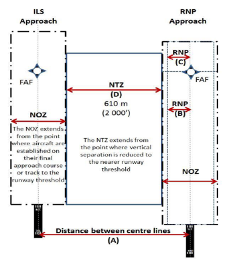
(ii) the RNP value for B, and the RNP value for C, if that part of the approach is within the horizontal separation minimum of a parallel approach, does not exceed (A-D)/2 (see Figure 51);
Figure 51: Distance between centre lines, NTZ and NOZ
(3) an APV procedure designed using either the RNP APCH or RNP AR APCH navigation specification, provided that:
(i) an appropriate documented safety assessment has shown that an acceptable level of safety can be met;
(ii) operations are approved by the competent authority; and
(iii) the instrument approach is demonstrated to protect the NTZ from infringement during normal operations;
(e) the nominal tracks of the missed approach procedures diverge by at least 30 degrees;
(f) an obstacle survey and evaluation is completed, as appropriate, for the areas adjacent to the final approach segments;
(g) aircraft are advised as early as possible, of the assigned runway, instrument approach procedure and any additional information considered necessary to confirm correct selection;
(h) the final approach course or track is intercepted by use of either:
(1) a published arrival and approach procedures that intercept with the IAF or the intermediate approach fix (IF); or
(2) vectoring, provided that:
(i) the final vector meets the following conditions:
(A) enable the aircraft to intercept at an angle not greater than 30 degrees;
(B) provide at least 1.9 km (1.0 NM) straight and level flight prior to the final approach course or track intercept; and
(C) enable the aircraft to be established on the final approach course or track in level flight for at least 3.7 km (2.0 NM) prior to intercepting the glide path or vertical path for the selected instrument approach procedure;
(ii) when assigning the final vector, the aircraft is advised of:
(A) the runway to which the approach is being made;
(B) its position relative to a fix on the final approach course or track;
(C) the altitude to be maintained until established on the final approach course or track, to the glide path or vertical path intercept point; and
(D) if required, clearance for the appropriate approach.
(i) an NTZ at least 610 m (2 000 ft) wide is established equidistant between extended runway centre lines and is depicted on the ATS surveillance system situation display;
(j) a minimum of a nominal 300 m (1 000 ft) vertical separation or, subject to ATS surveillance system capabilities, a minimum of 5.6 km (3.0 NM) horizontal separation is provided between aircraft on adjacent approaches until the aircraft are established inbound on a final approach course or track, or on an RNP AR APCH approach, and within the normal operating zone (NOZ);
(k) a minimum of 5.6 km (3.0 NM) horizontal separation, or a minimum of 4.6 km (2.5 NM) horizontal separation if so determined in accordance with point (a) of ATS.TR.215, is provided between aircraft established on the same final approach course or track, unless increased longitudinal separation is required due to wake turbulence;
(l) the approaches to each runway are monitored with an ATS surveillance system by separate air traffic controllers (referred to as monitoring controllers) different than those in point (a) above for each runway, or, if determined by a safety assessment and approved by the competent authority, by a single monitoring controller for no more than two runways:
(1) on dedicated radio channels, or when no such channels are available to the monitoring controller until landing, it is assured that:
(i) transfer of communication of aircraft to the respective aerodrome air traffic controller’s channel is effected before either of the two aircraft on adjacent final approach tracks intercepts the glide path or vertical path for the selected instrument approach procedure; and
(ii) the air traffic controller(s) monitoring the approaches to each runway are provided with the capability to override transmissions of aerodrome control on the respective radio channels for each arrival flow;
(2) so that when the nominal 300 m (1 000 ft) vertical separation is reduced:
(i) the applicable minimum longitudinal separation between aircraft on the same final approach course or track is maintained; and
(ii) aircraft do not penetrate the depicted NTZ by issuing instructions as follows:
(A) when it is observed that an aircraft overshoots the turn-on or continues on a track which will penetrate the NTZ, the aircraft is instructed to return immediately to the correct track; or
(B) when an aircraft is observed penetrating the NTZ, the aircraft on the adjacent final approach course or track is instructed to immediately climb and turn to the assigned altitude/height and heading (break-out procedure) in order to avoid the deviating aircraft. Where parallel approach obstacle assessment surfaces (PAOAS) criteria are applied for the obstacle assessment, the monitoring controller (see below in point (f)) should not issue the heading instruction to the aircraft below 120 m (400 ft) above the runway threshold elevation, and the heading instruction should not exceed 45 degrees track difference with the final approach course or track;
(3) the monitoring is provided until:
(i) separation as stipulated in point (b)(1) of AMC3 ATS.TR.210(c)(2) is applied, provided the established procedures ensure that monitoring controllers are advised whenever such separation is applied; or
(ii) the aircraft has landed, or in case of a missed approach, is at least 1.9 km (1.0 NM) beyond the departure end of the runway and adequate separation with any other traffic is established;
(m) the meteorological conditions under which independent parallel approaches are suspended for runway centre lines which are spaced less than 1 525 m (5 000 ft) are defined by the air traffic services provider and approved by the competent authority.
GM1 to AMC2 ATS.TR.255 Operations on parallel or near-parallel runways
ED Decision 2020/008/R
The information that independent parallel operations are in force may be provided through the ATIS broadcasts.
GM2 to AMC2 ATS.TR.255 Operations on parallel or near-parallel runways
ED Decision 2020/008/R
HIGH-RESOLUTION DISPLAY
With reference to point (c)(1)(iii) of AMC2 ATS.TR.255, a high-resolution display should:
(a) enable the air traffic controller to determine whether an aircraft is correctly aligned with the intended trajectory;
(b) depict the NTZ(s);
(c) be able to display any obstacle that would adversely affect a break-out procedure; and
(d) accurately reflect the azimuth accuracy prescribed in point (c)(1)(i)(A) of AMC2 ATS.TR.255.
GM3 to AMC2 ATS.TR.255 Operations on parallel or near-parallel runways
ED Decision 2020/008/R
PRECISION APPROACH PROCEDURE
With reference to point (d)(1) of AMC2 ATS.TR.255, the precision approach procedure that aligns the aircraft with the extended runway centre line may include one of the following: ILS, GLS, MLS or SBAS CAT I, when applicable, for the final approach segment.
GM4 to AMC2 ATS.TR.255 Operations on parallel or near-parallel runways
ED Decision 2020/008/R
PRECISION APPROACH PROCEDURE — DEMONSTRATION OF SAFETY
With reference to point (d)(3) of AMC2 ATS.TR.255, the demonstration of the safety of an APV procedure designed using either RNP APCH or RNP AR APCH navigation specification during simultaneous approaches may consider, inter alia:
(a) the collision risk from normal and residual (not mitigated) atypical errors;
(b) likelihood of ACAS nuisance alerting during normal operations;
(c) wake hazard;
(d) monitoring and available levels of system automation;
(e) data base management;
(f) flight management system input and related crew workload;
(g) impacts of meteorological conditions and other environmental factors; and
(h) training and published ATC break-out procedures.
GM5 to AMC2 ATS.TR.255 Operations on parallel or near-parallel runways
ED Decision 2020/008/R
SAFETY ASSESSMENT
With reference to point (l) of AMC2 ATS.TR.255, the conduct of safety assessments to enable the monitoring of not more than two runways by a single air traffic controller should review factors such as, but not limited to, complexity, times of operation, traffic mix and density, arrival rate, available levels of system automation, availability of back-up systems, impacts of meteorological conditions and other environmental factors.
GM6 to AMC2 ATS.TR.255 Operations on parallel or near-parallel runways
ED Decision 2020/008/R
MONITORING CONTROLLER
With reference to point (l) of AMC2 ATS.TR.255:
(a) Independent operations on parallel runways can only be conducted if there are means to ensure that the objectives of the air traffic services would be fulfilled in a manner similar to what the application of separation minima (vertical or horizontal) would achieve.
(b) Considering the geometry of two aircraft operating simultaneously on the parallel runways, while longitudinal separation is applied between aircraft approaching the same runway, a lateral separation is needed between the aircraft operating on parallel approaches for the most critical scenario: two aircraft at the same time on each final approach.
(c) To provide the acceptable lateral separation in such circumstances, an NTZ is established. The NTZ is considered to provide the lateral separation from the moment vertical separation between aircraft on adjacent approaches no longer exists until aircraft have landed. The responsibility of air traffic controllers is to closely monitor the progress of the flights and to immediately react when an aircraft deviates towards the NTZ boundary.
(d) In that sense, the tasks of these air traffic controllers (referred to as ‘monitoring controllers’), are as follows:
(1) to ensure that the NTZ is not penetrated when vertical separation is reduced;
(2) to instruct aircraft observed to overshoot the turn-on or to continue on a track which will penetrate the NTZ to return immediately to the correct track;
(3) to ensure that the applicable minimum longitudinal separation between aircraft on the same final approach course or track is maintained;
(4) if no dedicated radio channels are available for the monitoring controllers to control aircraft until landing, to transfer communication with the aircraft to the respective channel of the aerodrome air traffic controller before either of the two aircraft on adjacent final approach tracks intercepts the glide path or vertical path for the selected instrument approach procedure. In this case, the controllers monitoring the approaches to each runway are provided with the capability to override transmissions of aerodrome control on the respective radio channels for each arrival flow;
(5) if dedicated radio channels are available for the monitoring controllers to relay the landing clearances received from the aerodrome air traffic controller, or when the aerodrome air traffic controller informs that visual separation can be applied, to transfer the communications to the aerodrome air traffic controller;
(6) when an aircraft is observed penetrating the NTZ, to instruct the aircraft on the adjacent final approach course or track to immediately climb and turn to an assigned altitude/height and heading (break-out procedures) in order to avoid the deviating aircraft. Where PAOAS criteria are applied for the obstacle assessment, the monitoring controller will not issue the heading instruction to the aircraft below 120 m (400 ft) above the runway threshold elevation, and the heading instruction will not exceed 45 degrees track difference with the final approach course or track; and
(7) to terminate monitoring when either:
(i) visual separation is applied provided that procedures ensure that both monitoring controllers are advised whenever visual separation is applied; or
(ii) the aircraft has landed or, in case of a missed approach, is at least 1 NM beyond the departure end of the runway and adequate separation with other traffic is established.
(e) When there is a large deviation from the final approach track, communication between the controllers and pilots involved is critical. For independent parallel approaches, monitoring controllers are required, for each runway, with separate control frequencies. The monitoring controller(s) can transmit on either of these frequencies, automatically overriding transmissions by the other aerodrome air traffic controllers, or can use dedicated radio channels, if available. It is essential that a check of the override capability at each monitor position be performed prior to the monitoring controllers assuming responsibility of the position. The air traffic services provider should take steps to ensure that, in the event of a deviation, the monitoring controller will be able to contact the deviating aircraft and the endangered aircraft immediately. This will involve studying the proportion of time during which communications are blocked.
(f) Monitoring of approaches to no more than two runways by a single monitoring controller may be permitted if determined by a safety assessment and approved by the competent authority, as described below.
(g) During simultaneous independent approach operations, participating aircraft are established on guidance to instrument approach procedures which have been designed to not interfere with one another. By remaining on their guidance, the aircraft are, by design, not threats to each other, and are considered separated. If either aircraft deviates from its lateral path defined by its assigned instrument approach, separation is no longer assured. To protect against operational errors, system or equipment failures, etc., Simultaneous Operations on Parallel or Near-Parallel Instrument Runways (SOIR) procedures require the monitoring controller to provide intervention as necessary. Monitoring controllers are required to identify and respond to such traffic transgressions in a timely manner to protect proximate traffic and minimise collision risk. Their responsibility is to recognise a deviation from a cleared lateral path, determine a manoeuvre for any nearby traffic that might be threatened by this deviation that will avoid a collision, and transmit this manoeuvre instruction to the threatened aircraft. If there is no threatened traffic, or after the threatened traffic has begun its escape manoeuvre, the monitoring controller will also attempt to instruct the deviating aircraft.
(h) The time budgeted for recognition by monitoring controller of potential collision during non-nominal events in simultaneous parallel approaches is in the order of seconds. System-generated alerts to the monitoring controller that can differentiate quickly and accurately between normal and non-nominal situations will be an enabling element of the operation. The region known as NTZ is used to provide air traffic controllers with time to identify that one aircraft on a simultaneous approach may threaten the other and to then take appropriate action to avoid a collision. Normally, a dedicated monitoring controller is assigned to each approach during simultaneous operations. However, since a single NTZ is defined in the space between simultaneous approaches, it may be possible for a single controller to effectively monitor and correct any transgressing aircraft. Approval of an alternate to the otherwise-required approach-specific monitor control positions should consider, as a minimum, the following elements unique to a specific approach pairing:
(1) Approach geometry complexity:
(i) displaced thresholds which cause non-coincident altitudes along the parallel tracks;
(ii) use of curved course transitions to final; and
(iii) short finals.
(2) Traffic mix and density:
(i) mix of light-heavy traffic necessitating varying longitudinal wake spacing; and
(ii) approach speed variations.
(3) Arrival rate and density:
(i) total traffic volume versus approach capacity; and
(ii) flow management consistency with traffic demand.
(4) Available levels of system automation:
(i) conformance monitoring tools; and
(ii) non-transgression alerting.
(5) Availability of back-up systems to provide continuity of:
(i) communication;
(ii) approach navigation (approach technology);
(iii) surveillance (independent, redundant sources); and
(iv) interdependency of CNS.
(6) The impacts of local meteorological conditions and other environmental factors:
(i) inversion on final that can cause wake vortices to not dissipate;
(ii) excessive tailwind;
(iii) high cross-winds;
(iv) gusty winds; and
(v) inconsistent wind patterns (e.g. caused by nearby obstacles or terrain).
GM7 to AMC2 ATS.TR.255 Operations on parallel or near-parallel runways
ED Decision 2020/008/R
SUSPENSION OF INDEPENDENT PARALLEL OPERATIONS DUE TO METEOROLOGICAL CONDITIONS
With reference to point (m) of AMC2 ATS.TR.255:
(a) The meteorological conditions to be considered include, but are not limited to, the following:
(1) wind shear;
(2) turbulence;
(3) downdrafts; and
(4) crosswind and significant meteorological conditions such as thunderstorms, which might otherwise increase deviations from the final approach course or track to the extent that safety may be impaired.
(b) Guidance relating to meteorological conditions is contained in the ICAO Doc 9643 ‘Manual on Simultaneous Operations on Parallel or Near-Parallel Instrument Runways (SOIR)’.
AMC3 ATS.TR.255 Operations on parallel or near-parallel runways
ED Decision 2020/008/R
REQUIREMENTS AND PROCEDURES FOR DEPENDENT PARALLEL APPROACHES
Dependent parallel approaches should only be conducted to parallel runways when the following conditions are met:
(a) separate air traffic controllers are responsible for the sequencing and spacing of arriving aircraft to each runway;
(b) the runway centre lines are spaced by 915 m (3 000 ft) or more;
(c) the final approach course or track is intercepted by use of:
(1) vectoring; or
(2) a published arrival and approach procedures that intercepts with the IAF or the IF.
(d) an ATS surveillance system with a minimum SSR azimuth accuracy of 0.3 degrees (one sigma), or for MLAT or ADS-B a performance capability equivalent to or better than the SSR requirement can be demonstrated and an update period of 5 seconds or less is available;
(e) the instrument flight procedure that aligns the aircraft with the extended runway centre line is one of the following:
(1) a precision approach procedure;
(2) an APV procedure designed using the RNP AR APCH navigation specification, provided that the RNP value for B, and the RNP value for C if that segment of the approach is within the horizontal separation minimum of a parallel approach, does not exceed one quarter of the distance between runway centre lines (A) (See Figure 52);
(3) an APV procedure designed using the RNP AR APCH navigation specification that does not meet the provisions in point (2) above or an RNP APCH, provided that:
(i) an appropriate, documented safety assessment has shown that an acceptable level of safety can be met; and
(ii) operations are approved by the competent authority;
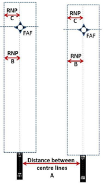
Figure 52: RNP value and distance between centre lines
(f) aircraft are advised that approaches are in use to both runways;
(g) the nominal tracks of the missed approach procedures diverge by at least 30 degrees;
(h) the approach control unit has the capability to override the frequencies used by the aerodrome control tower;
(i) a minimum of nominal 300 m (1 000 ft) vertical separation or a minimum of 5.6 km (3.0 NM) horizontal separation is provided between aircraft until established on the final approach courses or tracks of parallel approaches;
(j) the minimum horizontal separation to be provided between aircraft established on the same final approach course or track is 5.6 km (3.0 NM), or 4.6 km (2.5 NM) horizontal separation if so determined in accordance with ATS.TR.215, unless increased longitudinal separation is required due to wake turbulence;
(k) the minimum horizontal separation to be provided diagonally between successive aircraft on adjacent final approach courses or tracks is:
(1) 3.7 km (2.0 NM) between successive aircraft on adjacent final approach courses or tracks more than 2 529 m (8 300 ft) apart (See figure 53); or

Figure 53: Diagonal separation for distance between centre lines greater than 2 529 m (8 300 ft)
(2) 2.8 km (1.5 NM) between successive aircraft on adjacent final approach courses or tracks more than 1 097 m (3 600 ft) but not more than 2 529 m (8 300 ft) apart (see Figure 54); or

Figure 54: Diagonal separation for distance between centre lines greater than 1 097 m (3 600 ft) but less than or equal to 2 529 m (8 300 ft)
(3) 1.9 km (1.0 NM) between successive aircraft on adjacent final approach courses or tracks more than 915 m (3 000 ft) but not more than 1 097 m (3 600 ft) apart (see Figure 55).

Figure 55: Diagonal separation for distance between centre lines greater than 915 m (3 000 ft) but less than or equal to 1 097 m (3 600 ft)
GM1 to AMC3 ATS.TR.255 Operations on parallel or near-parallel runways
ED Decision 2020/008/R
PRECISION APPROACH PROCEDURES
With reference to point (e)(1) of AMC3 ATS.TR.255, the precision approach procedure that aligns the aircraft with the extended runway centre line may include one of the following: ILS, GLS, MLS or SBAS CAT I, when applicable, for the final approach segment.
GM2 to AMC3 ATS.TR.255 Operations on parallel or near-parallel runways
ED Decision 2020/008/R
ATIS BROADCAST
With reference to point (f) of AMC3 ATS.TR.255, the information that dependent parallel operations are in force may be provided through the ATIS broadcasts.
AMC4 ATS.TR.255 Operations on parallel or near-parallel runways
ED Decision 2020/008/R
REQUIREMENTS AND PROCEDURES FOR SEGREGATED PARALLEL OPERATIONS
Segregated parallel operations should only be conducted on parallel runways when the following conditions are met:
(a) the runway centre lines are spaced by a minimum of 760 m (2 500 ft) (see Figure 56). Such minimum may be decreased by 30 m for each 150 m that the arrival runway is staggered toward the arriving aircraft, to a minimum of 300 m (see Figure 57), and should be increased by 30 m for each 150 m that the arrival runway is staggered away from the arriving aircraft (see Figure 58);
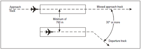
(b) the nominal departure track diverges immediately after take-off by at least 30 degrees from the missed approach track of the adjacent approach (see Figure 56);
Figure 56: Segregated parallel operations
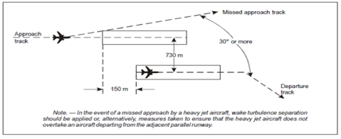
Figure 57: Segregated parallel operations where runways are staggered
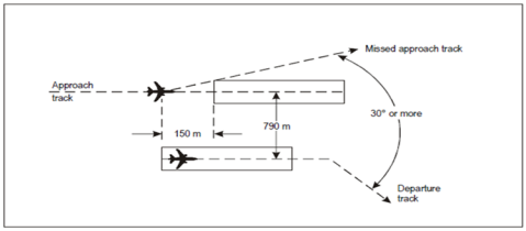
Figure 58: Segregated parallel operations where runways are staggered
(c) the instrument flight procedure that aligns the aircraft with the extended runway centre line is one of the following:
(1) precision approaches and/or APV (RNP AR APCH, RNP APCH);
(2) surveillance radar approach (SRA);
(3) visual approach; and
(d) a suitable ATS surveillance system and the appropriate ground facilities conform to the standard necessary for the specific type of approach in point (c) above.
GM1 to AMC2 ATS.TR.255; AMC3 ATS.TR.255 and AMC4 ATS.TR.255 Operations on parallel or near-parallel runways
ED Decision 2020/008/R
DETERMINATION THAT AN AIRCRAFT IS ESTABLISHED ON RNP AR APCH
(a) An aircraft conducting an RNP AR APCH procedure (in accordance with Regulation (EU) 2018/1048) is considered to be established for the entire approach procedure after the IAF or the IF, as applicable, provided that:
(1) the aircraft confirms that it is established on the RNP AR APCH procedure prior to a designated point, the location of which is to be determined by the competent authority;
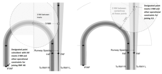
(2) the designated point is positioned on the RNP AR APCH to ensure the applicable horizontal separation minimum (e.g. 5.6 km (3 NM)) from the adjacent approach procedure (see Figure 59). The designated point may normally be coincident with the IAF; and
Figure 59: Established on RNP AR APCH concept
(RNP AR APCH/precision approach with 3 NM separation minimum example)
(3) the designated point is readily apparent to the approach and monitoring air traffic controllers, to facilitate the application of the procedure. The designated point may be depicted on the situation display.
(b) Attention is drawn to the application of the appropriate wake turbulence separation between aircraft on the same approach, as established in ATS.TR.220.
(c) If, after reporting that it is established on the RNP AR APCH procedure, the aircraft is unable to execute the procedure, the pilot is expected to notify the air traffic controller immediately with a proposed course of action, and thereafter follow ATC instructions (e.g. break-out procedure).
(d) In circumstances where a break-out procedure becomes necessary during the application of the independent parallel approach procedure (for example, an aircraft penetrating the NTZ), monitoring controllers may issue climb and/or heading instructions to an aircraft established on an RNP AR APCH. Guidance on break-out procedures is contained in ICAO Doc 9643 ‘Manual on Simultaneous Operations on Parallel or Near-Parallel Instrument Runways (SOIR)’.
(e) To support a break-out instruction, an obstacle assessment is to be completed, in accordance with Regulation (EU) 2017/373. Guidance on obstacle assessment is contained in ICAO Doc 9643 ‘Manual on Simultaneous Operations on Parallel or Near-Parallel Instrument Runways (SOIR)’.
(f) Where appropriate, break-out procedures are published in the AIP and in the local instructions.
GM1 ATS.TR.255 Operations on parallel or near-parallel runways
ED Decision 2020/008/R
Guidance material relating to operations on parallel or near-parallel runways is contained in ICAO Doc 9643 ‘Manual on Simultaneous Operations on Parallel or Near-Parallel Instrument Runways (SOIR)’.
ATS.TR.260 Selection of the runway-in-use
Commission Implementing Regulation (EU) 2020/469
The aerodrome control tower shall select the runway-in-use for take-off and landing of aircraft taking into consideration the surface wind speed and direction as well as other local relevant factors, such as:
(a) runway configuration;
(b) meteorological conditions;
(c) instrument approach procedures;
(d) approach and landing aids available;
(e) aerodrome traffic circuits and air traffic conditions;
(f) length of the runway or runways;
(g) other factors indicated in local instructions.
AMC1 ATS.TR.260(g) Selection of the runway-in-use
ED Decision 2020/008/R
CONSIDERATION OF NOISE ABATEMENT IN THE SELECTION OF THE RUNWAY-IN-USE
(a) The aerodrome control tower should select runways for noise abatement purposes for landing operations only when they are equipped with suitable glide path guidance, e.g. ILS, or a visual approach slope indicator system for operations in VMC.
(b) Noise abatement should not be a determining factor in runway nomination under the following circumstances:
(1) if the runway surface conditions are adversely affected (e.g. by snow, slush, ice, water, mud, rubber, oil or other substances);
(2) for landing in conditions:
(i) when the ceiling is lower than 150 m (500 ft) above aerodrome elevation, or the visibility is less than 1 900 m; or
(ii) when the approach requires use of vertical minima greater than 100 m (300 ft) above aerodrome elevation and:
(A) the ceiling is lower than 240 m (800 ft) above aerodrome elevation; or
(B) the visibility is less than 3 000 m;
(3) for take-off when the visibility is less than 1 900 m;
(4) when wind shear has been reported or forecast or when thunderstorms are expected to affect the approach or departure; and
(5) when the crosswind component, including gusts, exceeds 28 km/h (15 kt), or the tailwind component, including gusts, exceeds 9 km/h (5 kt).
GM1 ATS.TR.260 Selection of the runway-in-use
ED Decision 2020/008/R
(a) Normally, an aircraft will land and take off into wind.
(b) Departing aircraft may be expedited by suggesting a take-off direction which is not into the wind. It is the responsibility of the pilot-in-command of an aircraft to decide between making such a take-off or waiting for take-off in a preferred direction.
GM1 ATS.TR.260(e) Selection of the runway-in-use
ED Decision 2020/008/R
DESCRIPTION OF AIR TRAFFIC CONDITIONS
When considering the air traffic conditions for the selection of the runway-in-use, the following elements, inter alia, should be evaluated:
(a) traffic complexity;
(b) traffic density;
(c) task complexity; and
(d) traffic typology (e.g. prevalent aircraft types operating at the aerodrome and preferred runway-in-use.
ATS.TR.265 Control of aerodrome surface traffic in low-visibility conditions
Commission Implementing Regulation (EU) 2020/469
(a) When there is a requirement for traffic to operate on the manoeuvring area in conditions of visibility which prevent the aerodrome control tower from applying visual separation between aircraft, and between aircraft and vehicles, the following shall apply:
(1) at the intersection of taxiways, an aircraft or vehicle on a taxiway shall not be permitted to hold closer to the other taxiway than the holding position limit defined by intermediate holding positions, stop bar or taxiway intersection marking, in accordance with the applicable aerodrome design specifications;
(2) the longitudinal separation method on taxiways shall be as specified for each particular aerodrome by the air traffic services provider and approved by the competent authority, taking into account the characteristics of the aids available for surveillance and control of ground traffic, the complexity of the aerodrome layout and the characteristics of the aircraft using the aerodrome.
(b) Procedures applicable to the start and continuation of low-visibility operations shall be established in accordance with point ATS.OR.110 and shall be approved by the competent authority.
GM1 ATS.TR.265(a)(1) Control of aerodrome surface traffic in low-visibility conditions
ED Decision 2020/008/R
HOLDING POSITION LIMITS
The definition of holding position limits by intermediate holding positions, stop bar or taxiway intersection marking is established in accordance with EASA ED Decision 2014/013/R ‘Certification Specification and Guidance Material for Aerodrome Design’, as amended.
AMC1 ATS.TR.265(b) Control of aerodrome surface traffic in low-visibility conditions
ED Decision 2020/008/R
PROCEDURES FOR CONTROL OF AERODROME TRAFFIC IN LOW-VISIBILITY OPERATIONS (LVOs)
(a) LVOs should be initiated by or through the aerodrome control tower.
(b) The aerodrome control tower should inform the approach control unit concerned when procedures for precision approach in LVOs will be applied and also when such procedures are no longer in force.
(c) Provisions regarding LVOs should specify:
(1) for the different types of LVOs, the RVR value(s) at which the LVOs procedures are to be implemented;
(2) the minimum navigation equipment requirements for LVOs;
(3) other facilities and aids required for LVOs, including aeronautical ground lights, which are to be monitored for normal operation;
(4) the criteria for and the circumstances under which downgrading of the navigation equipment from LVOs capability is to be made;
(5) the requirement to report any relevant equipment failure and degradation, without delay, to the flight crews concerned, the approach control unit, the aerodrome operator and, where established, the organisation(s) providing apron management services, and any other appropriate organisation;
(6) special procedures for the control of traffic on the manoeuvring area, including:
(i) the runway-holding positions to be used;
(ii) the minimum distance between an arriving and a departing aircraft to ensure protection of the sensitive and critical areas;
(iii) procedures to verify that aircraft and vehicles have vacated the runway; and
(iv) procedures applicable to the separation of aircraft and vehicles;
(7) the applicable spacing between successive approaching aircraft;
(8) the action(s) to be taken in the event that LVOs need to be discontinued, e.g. due to equipment failures; and
(9) any other relevant procedures or requirements.
(d) The aerodrome control tower should, prior to a period of application of low-visibility procedures, establish a record of vehicles and persons currently on the manoeuvring area and maintain this record during the period of application of these procedures to assist in assuring the safety of operations on that area.
ATS.TR.270 Authorisation of special VFR
Commission Implementing Regulation (EU) 2020/469
(a) Special VFR flights may be authorised to operate within a control zone, subject to an ATC clearance. Except when permitted by the competent authority for helicopters in special cases such as but not limited to police, medical, search and rescue operations and firefighting flights, the following additional conditions shall be applied:
(1) such special VFR flights may be conducted during day only, unless otherwise permitted by the competent authority;
(2) by the pilot:
(i) clear of cloud and with the surface in sight;
(ii) the flight visibility is not less than 1 500 m or, for helicopters, not less than 800 m;
(iii) fly at a speed of 140 kt IAS or less to give adequate opportunity to observe other traffic and any obstacles in time to avoid a collision;
(3) An air traffic control unit shall not issue a special VFR clearance to aircraft to take off or land at an aerodrome within a control zone, or enter the aerodrome traffic zone or aerodrome traffic circuit when the reported meteorological conditions at that aerodrome are below the following minima:
(i) the ground visibility is less than 1 500 m or, for helicopters, less than 800 m;
(ii) the ceiling is less than 180 m (600 ft).
(b) An air traffic control unit shall handle requests for such an authorisation individually.
GM1 ATS.TR.270 Authorisation of special VFR
ED Decision 2020/008/R
SPECIAL VFR — DEVIATIONS
The list of type of operations subject to permit by the competent authority to deviate from the requirements for special VFR flights is not exhaustive. The competent authority may grant a permit for other kinds of helicopter operations such as power line inspections, helicopter hoist operations, etc.
GM1 ATS.TR.270(a)(3) Authorisation of special VFR
ED Decision 2020/008/R
SPECIAL VFR IN CONTROL ZONES
When the reported ground visibility at the aerodrome is less than 1 500 m, air traffic control units may issue a special VFR clearance for a flight crossing the control zone and not intending to take off or land at an aerodrome within a control zone, or enter the aerodrome traffic zone or aerodrome traffic circuit when the flight visibility reported by the pilot is not less than 1 500 m, or, for helicopters, not less than 800 m.
