
AMC 20-3B Certification of Engines Equipped with Electronic Engine Control Systems
ED Decision 2020/010/R
The existing certification specifications of CS-E for Engine certification may require specific interpretation for Engines equipped with Electronic Engine Control Systems (EECS), with special regard to interface with the certification of the aircraft and/or Propeller when applicable. Because of the nature of this technology, it has been considered useful to prepare acceptable means of compliance (AMC) specifically addressing the certification of these control systems.
Like any AMC, it is issued to outline issues to be considered during the demonstration of compliance with CS-E.
This AMC is relevant to Engine certification specifications for EECS, whether they use electrical or electronic (analogue or digital) technology. This is in addition to other AMC such as AMC E 50 or AMC E 80.
It gives guidance on the precautions to be taken for the use of electrical and electronic technology for Engine control, protection, limiting and monitoring functions, and, where applicable, for the integration of aircraft or Propeller functions. In the latter case, this document is applicable to such functions integrated into the EECS, but only to the extent that these functions affect compliance with CS-E specifications.
The text deals mainly with the thrust and power functions of an EECS, since this is the prime function of the Engine. However, there are many other functions, such as bleed valve control, that may be integrated into the system for operability reasons. The principles outlined in this AMC apply to the whole EECS.
This document also discusses the division of compliance tasks for certification between the applicants for Engine, Propeller (when applicable), and aircraft type certificates. This guidance relates to issues to be considered during Engine certification. AMC 20-1() addresses issues associated with the Engine installation in the aircraft.
The introduction of electrical and electronic technology can entail the following:
— greater dependence of the Engine on the aircraft owing to the increased use of electrical power or data supplied from the aircraft;
— increased integration of control and related indication functions;
— increased risk of significant Failures that are common to more than one Engine of the aircraft which might, for example, occur as a result of:
— insufficient protection from electromagnetic disturbance (e.g. lightning, internal or external radiation effects) (see CS-E 50(a)(1), CS E-80 and CS-E 170);
— insufficient integrity of the aircraft electrical power supply (see CS-E 50(h));
— insufficient integrity of data supplied from the aircraft (see CS-E 50(g));
— hidden design Faults or discrepancies contained within the design of the propulsion system control software or airborne electronic hardware (AEH) (see CS-E 50(f)); or
— omissions or errors in the system/software/AEH specification (see CS-E 50(f)).
Appropriate design and integration precautions should therefore be taken to minimise any adverse effects from the above.
(3) RELEVANT SPECIFICATIONS AND REFERENCE DOCUMENTS
Although compliance with many CS-E specifications might be affected by the Engine Control System, the main paragraphs relevant to the certification of the Engine Control System itself are the following:
|
CS-E Specification |
Turbine Engines |
Piston Engines |
|
CS-E 20 (Engine configuration and interfaces) |
|
|
|
CS-E 25 (Instructions for Continued Airworthiness) |
|
|
|
CS-E 30 (Assumptions) |
|
|
|
CS-E 50 (Engine Control System) |
|
|
|
CS-E 60 (Provision for instruments) |
|
|
|
CS-E 80 (Equipment) |
|
|
|
CS-E 110 (Drawing and marking of parts — Assembly of parts) |
|
|
|
CS-E 130 (Fire prevention) |
|
|
|
CS-E 140 (Tests-Engine configuration) |
|
|
|
CS-E 170 (Engine systems and component verification) |
|
|
|
CS-E 210 (Failure analysis) |
|
|
|
CS-E 250 (Fuel System) |
|
|
|
CS-E 390 (Acceleration tests) |
|
|
|
CS-E 500 (Functioning) |
|
|
|
CS-E-510 (Safety analysis) |
|
|
|
CS-E 560 (Fuel system) |
|
|
|
CS-E 745 (Engine Acceleration) |
|
|
|
CS-E 1030 (Time-limited dispatch) |
|
|
The following documents are referenced in AMC 20-3B:
— International Electrotechnical Commission (IEC), Central Office, 3, rue de Varembé, P.O. Box 131, CH - 1211 GENEVA 20, Switzerland
— IEC/PAS 62239, Electronic Component Management Plans, edition 1.0, dated April 2001
— IEC/PAS 62240, Use of Semiconductor Devices Outside Manufacturers’ Specified Temperature Ranges, edition 1.0, dated April 2001
— RTCA, Inc. 1828 L Street, NW, Suite 805, Washington, DC 20036 or EUROCAE, 17, rue Hamelin, 75116 Paris, France
— RTCA DO-254/ EUROCAE ED-80, Design Assurance Guidance for Airborne Electronic Hardware, dated April 19, 2000
— RTCA DO-160/EUROCAE ED 14, Environmental Conditions and Test Procedures for Airborne Equipment
— AMC 20-115 on software considerations for certification of airborne systems and equipment
— Aeronautical Systems Center, ASC/ENOI, Bldg 560, 2530 Loop Road West, Wright‑Patterson AFB, OH, USA, 45433-7101
— MIL-STD-461E, Requirements for the Control of Electromagnetic Interference Characteristics, dated August 20, 1999
— MIL-STD-810 E or F, Test Method Standard for Environmental Engineering, E dated July 14, 1989, F dated January 1, 2000
— U.S. Department of Transportation, Subsequent Distribution, Office Ardmore East Business Center, 3341 Q 75th Ave, Landover, MD, USA, 20785
— AC 20-136, Protection of Aircraft Electrical/Electronic Systems Against the Indirect Effects of Lightning, dated March 5, 1990
— Society of Automotive Engineers (SAE), 400 Commonwealth Drive, Warrendale, PA 15096-0001 USA or EUROCAE, 17, rue Hamelin, 75116 Paris, France
— SAE ARP 5412 / EUROCAE ED-84, with Amendment 1 & 2, Aircraft Lightning Environment and Related Test Waveforms, February 2005/May 2001 respectively
— SAE ARP 5413 / EUROCAE ED-81, with Amendment 1, Certification of Aircraft Electrical/Electronic Systems for the Indirect Effects of Lightning, November 1999/August 1999 respectively
— SAE ARP 5414 / EUROCAE ED-91, with Amendment 1, Aircraft Lightning Zoning, February 2005/June 1999 respectively
— SAE ARP 5416 / EUROCAE ED-105, Aircraft Lightning Test Methods, March 2005/April 2005 respectively
(4) DEFINITIONS
The words defined in CS-Definitions and in CS-E 15 are identified by capital letters.
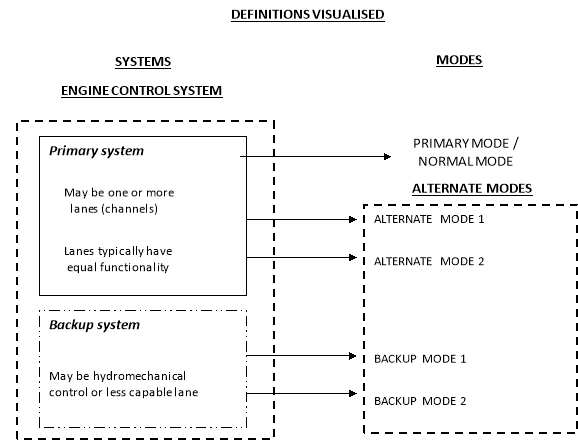
The following figure and associated definitions are provided to facilitate a clear understanding of the terms used in this AMC.
(5) GENERAL
It is recognised that the determination of compliance of the Engine Control System with the applicable aircraft certification specifications will only be made during the aircraft certification.
In the case where the installation is unknown at the time of Engine certification, the applicant for Engine certification should make reasonable installation and operational assumptions for the target installation. Any installation limitations or operational issues will be noted in the instructions for installation or operation, and/or the Type Certificate Data Sheet (TCDS) (see CS‑E 30 Assumptions).
When possible, early coordination between the Engine and the aircraft applicants is recommended in association with the relevant authorities as discussed under Section 15 of this AMC.
(6) SYSTEM DESIGN AND VALIDATION
The need to provide protective functions, such as overspeed protection, for all Control Modes, including any Alternate Modes, should be reviewed under the specifications of CS-E 50(c), (d) and (e), and CS-E 210 or CS-E 510.
Any limitations on operations in Alternate Modes should be clearly stated in the Engine instructions for installation and operation.
Descriptions of the functioning of the Engine Control System operating in its Primary and any Alternate Modes should be provided in the Engine instructions for installation and operation.
Analyses and/or testing are necessary to substantiate that operating in the Alternate Modes has no unacceptable effect on Engine durability or endurance. Demonstration of the durability and reliability of the control system in all modes is primarily addressed by the component testing of CS-E 170. Performing some portion of the Engine certification testing in the Alternate Mode(s) and during transition between modes can be used as part of the system validation required under CS-E 50(a).
(i) Engine Test Considerations
If the Engine certification tests defined in CS-E are performed using only the Engine Control System’s Primary Mode in the Full-up Configuration and if approval for dispatch in the Alternate Mode is requested by the applicant under CS-E 1030, it should be demonstrated, by analysis and/or test, that the Engine can meet the defined test-success criteria when operating in any Alternate Mode that is proposed as a dispatchable configuration as required by CS-E 1030.
Some capabilities, such as operability, blade-off, rain, hail, bird ingestion, etc., may be lost in some control modes that are not dispatchable. These modes do not require engine test demonstration as long as the installation and operating instructions reflect this loss of capability.
Availability of any Back-up Mode should be established by routine testing or monitoring to ensure that the Back-up Mode will be available when needed. The frequency of establishing its availability should be documented in the Instructions for Continued Airworthiness (ICA).
This AMC is not specifically intended to apply to any crew training modes. These modes are usually installation-, and possibly operator-, specific and need to be negotiated on a case-by-case basis. As an example, one common application of crew training modes is for simulation of the ‘failed-fixed’ mode on a twin-engine rotorcraft. Training modes should be described in the Engine instructions for installation and operation as appropriate. Also, precautions should be taken in the design of the Engine Control System and its crew interfaces to prevent inadvertent entry into any training modes. Crew training modes, including lock-out systems, should be assessed as part of the System Safety Analysis (SSA) of CS-E 50(d).
(c) Non-Dispatchable Configurations and Modes
For control configurations which are not dispatchable, but for which the applicant seeks to take credit in the system Loss of Thrust (or Power) Control (LOTC/LOPC) analysis, it may be acceptable to have specific operating limitations. In addition, compliance with CS‑E 50(a) does not imply strict compliance with the operability specifications of CS-E 390, CS-E 500 and CS-E 745 in these non-dispatchable configurations, if it can be demonstrated that, in the intended installation, no likely pilot control system inputs will result in Engine surge, stall, flame-out or unmanageable delay in power recovery. For example, in a twin-engine rotorcraft, a rudimentary Backup System may be adequate since frequent and rapid changes in power setting with the Backup System may not be necessary.
In addition to these operability considerations, other factors which should be considered in assessing the acceptability of such reduced-capability Backup Modes include:
— the installed operating characteristics of the Back-up Mode and the differences from the Primary Mode;
— the likely impact of the Back-up Mode operations on pilot workload, if the aircraft installation is known;
— the frequency of transfer from the Primary Mode to the Back-up Mode (i.e. the reliability of the Primary Mode); frequencies of transfer of less than 1 per 20 000 engine flight hours have been considered acceptable.
The intent of CS-E 50(b) is to ensure that any control transitions, which occur as a result of Fault Accommodation, occur in an acceptable manner.
In general, transition to Alternate Modes should be accomplished automatically by the Engine Control System. However, systems for which pilot action is required to engage the Backup Mode may also be acceptable. For instance, a Fault in the Primary System may result in a ‘failed-fixed’ fuel flow and some action is required by the pilot to engage the Backup System in order to modulate Engine power. Care should be taken to ensure that any reliance on manual transition is not expected to pose an unacceptable operating characteristic, unacceptable crew workload or require exceptional skill.
The transient change in power or thrust associated with transfer to Alternate Modes should be reviewed for compliance with CS-E 50(b). If available, input from the installer should be considered. Although this is not to be considered a complete list, some of the items that should be considered when reviewing the acceptability of Control Mode transitions are:
— The frequency of occurrence of transfers to any Alternate Mode and the capability of the Alternate Mode. Computed frequency-of-transfer rates should be supported with data from endurance or reliability testing, in-service experience on similar equipment, or other appropriate data.
— The magnitude of the power, thrust, rotor or Propeller speed transients.
— Successful demonstration, by simulation or other means, of the ability of the Engine Control System to control the Engine safely during the transition. In some cases, particularly those involving rotorcraft, it may not be possible to make a determination that the mode transition provides a safe system based solely on analytical or simulation data. Therefore, a flight test programme to support this data will normally be expected.
— An analysis should be provided to identify those Faults that cause Control Mode transitions either automatically or through pilot action.
— For turboprop or turboshaft engines, the transition should not result in excessive overspeed or underspeed of the rotor or Propeller which could cause emergency shutdown, loss of electrical generator power or the setting-off of warning devices.
The thrust or power change associated with the transition should be declared in the instructions for installing the Engine.
Any observable time delays associated with Control Mode, channel or system transitions or in re-establishing the pilot’s ability to modulate Engine thrust or power should be identified in the Engine instructions for installation and operation (see CS-E 50(b)). These delays should be assessed during aircraft certification.
(ii) Annunciation to the Flight Crew
If annunciation is necessary to comply with CS-E 50(b)(3), the type of annunciation to the flight crew should be commensurate with the nature of the transition. For instance, reversion to an Alternate Mode of control where the transition is automatic and the only observable changes in operation of the Engine are different thrust control schedules, would require a very different form of annunciation to that required if timely action by the pilot is required in order to maintain control of the aircraft.
The intent and purpose of the cockpit annunciation should be clearly stated in the Engine instructions for installation and operation, as appropriate.
Environmental conditions include electromagnetic interference (EMI), high-intensity radiated fields (HIRF) and lightning. The environmental conditions are addressed under CS-E 80 and CS-E 170. The following provides additional guidance for EMI, HIRF and lightning.
When the installation is known during the Engine type-certification programme, the Engine Control System should be tested at levels that have been determined and agreed by the Engine and aircraft applicants. It is assumed that, by this agreement, the installation can meet the aircraft certification specifications. Successful completion of the testing to the agreed levels would be accepted for Engine type certification. This, however, may make the possibility of installing the Engine dependent on a specific aircraft.
If the aircraft installation is not known or defined at the time of the Engine certification, in order to determine the levels to be declared for the Engine certification, the Engine applicant may use the external threat level defined at the aircraft level and use assumptions on installation attenuation effects.
If none of the options defined above are available, it is recommended that the procedures and minimum default levels for HIRF testing should be agreed with EASA.
The installed Engine Control System, including representative
Engine–aircraft interface cables, should be the basis for certification testing.
EMI test procedures and test levels conducted in accordance with MIL‑STD‑461 or EUROCAE ED 14/DO-160 have been considered acceptable.
The applicant should use the HIRF test guidelines provided in EUROCAE ED 14/RTCA DO-160 or equivalent. However, it should be recognised that the tests defined in EUROCAE ED 14/RTCA DO-160 are applicable at a component test level, requiring the applicant to adapt these test procedures to a system level HIRF test to demonstrate compliance with CS-E 80 and CS‑E 170.
For lightning tests, the guidelines of SAE ARP 5412, 5413, 5414 and 5416, and EUROCAE ED 14/RTCA DO-160 would be applicable.
Pin Injection Tests (PIT) are normally conducted as component tests on the EECS unit and other system components as required. PIT levels are selected as appropriate from the tables of EUROCAE ED 14/DO-160.
Environmental tests, such as MIL-STD-810, may be accepted in lieu of EUROCAE ED-14/DO-160 tests where these tests are equal to or more rigorous than those defined in EUROCAE ED 14/DO-160.
(B) Open-loop and Closed-loop Testing
HIRF and lightning tests should be conducted as system tests on closed-loop or open-loop laboratory set-ups.
The closed-loop set-up is usually provided with hydraulic pressure to move actuators to close the inner actuating loops. A simplified Engine simulation may be used to close the outer Engine loop.
Testing should be conducted with the Engine Control System controlling at the most sensitive operating point, as selected and detailed in the test plans by the applicant. The system should be exposed to the HIRF and lightning environmental threats while operating at the selected condition. There may be a different operating point for HIRF and lightning environmental threats.
For tests in open- and closed-loop set-ups, the following factors should also be considered:
— If a special EECS test software is used, that software should be developed at the criticality level determined by the Engine safety assessment process.
— The Engine Control System should be tested at the criticality levels that have been determined and agreed by the Engine and aircraft applicants. It is assumed that by this agreement, the installation meets the aircraft certification specifications. In some cases, the application code is modified to include the required test code features.
— The system test set-up should be capable of monitoring both the output signals and the input signals.
— Anomalies observed during open-loop testing on inputs or outputs should be duplicated on the Engine simulation to determine whether the resulting power or thrust perturbations comply with the pass–fail criteria.
The pass–fail criteria of CS-E 170 for HIRF and lightning should be interpreted as ‘no adverse effect’ on the functionality of the system.
The following are considered adverse effects:
— a greater than 3 % change of Take-off Power or Thrust for a period of more than 2 seconds;
— transfers to Alternate Channels, Backup Systems, or Alternate Modes;
— component damage;
— false annunciation to the flight crew, which could cause unnecessary or inappropriate flight crew action;
— erroneous operation of protection systems, such as overspeed or thrust reverser circuits.
AEH or software design changes implemented after the initial environmental testing should be evaluated for their effects with respect to the EMI, HIRF and lightning environment.
CS-E 25 requires that the applicant prepare Instructions for Continued Airworthiness (ICA). These include a maintenance plan. Therefore, for any protection system that is part of the type design of the Engine Control System and is required by the system to meet the qualified levels of EMI, HIRF and lightning, a maintenance plan should be provided to ensure the continued airworthiness for the parts of the installed system which are supplied by the Engine type-certificate holder.
The maintenance actions to be considered include periodic inspections or tests for required structural shielding, wire shields, connectors, and equipment protection components. Inspections or tests when the part is exposed may also be considered. The applicant should provide the engineering validation and substantiation of these maintenance actions.
(v) Time-Limited Dispatch (TLD) Environmental Tests
Although TLD is only an optional requirement for certification (see CS-E 1000 and CS-E 1030), EMI, HIRF and lightning tests for TLD are usually conducted together with tests conducted for certification. Acceptable means of compliance are provided in AMC E 1030.
(7) INTEGRITY OF THE ENGINE CONTROL SYSTEM
The intent of CS-E 50(c) is to establish Engine Control System integrity requirements consistent with operational requirements of the various installations. (See also paragraph (4) of AMC E 50).
(b) Definition of an LOTC/LOPC event
(i) For turbine Engines intended for CS-25 installations
An LOTC/LOPC event is defined as an event where the Engine Control System:
— has lost the capability of modulating thrust or power between idle and 90% of maximum rated power or thrust, or
— suffers a Fault which results in a thrust or power oscillation greater than the levels given in paragraph (7)(c) of this AMC, or
— has lost the capability to govern the Engine in a manner which allows compliance with the operability specifications given in CS-E 500(a) and CS-E 745.
(ii) For turbine Engines intended for rotorcraft
An LOPC event is defined as an event where the Engine Control System:
— has lost the capability of modulating power between idle and 90% of maximum rated power at the flight condition, except OEI power ratings, or
— suffers a Fault which results in a power oscillation greater than the levels given in paragraph (7)(c) of this AMC, or
— has lost the capability to govern the Engine in a manner which allows compliance with the operability specifications given in CS-E 500(a) and CS-E 745, with the exception that the inability to meet the operability specifications in the Alternate Modes may not be included as LOPC events.
— Single Engine rotorcraft will be required to meet the operability specifications in the Alternate Mode(s), unless the lack of this capability is demonstrated to be acceptable at the aircraft level. Engine operability in the Alternate Mode(s) is considered a necessity if:
— the control transitions to the Alternate Mode more frequently than the acceptable LOPC rate, or
— normal flight crew activity requires rapid changes in power to safely fly the aircraft.
— For multi-Engine rotorcraft, the LOPC definition may not need to include the inability to meet the operability specifications in the Alternate Mode(s). This may be considered acceptable because when one Engine control transitions to an Alternate Mode, which may not have robust operability, that Engine can be left at reasonably fixed power conditions. The Engine(s) with the normally operating control(s) can change power – as necessary – to complete aircraft manoeuvres and safely land the aircraft. Demonstration of the acceptability of this type of operation may be required at aircraft certification.
(iii) For turbine Engines intended for other installations
A LOTC/LOPC event is defined as an event where the Engine Control System:
— has lost the capability of modulating thrust or power between idle and 90% of maximum rated power or thrust, or
— suffers a Fault which results in a thrust or power oscillation that would impact controllability in the intended installation, or
— has lost the capability to govern the Engine in a manner which allows compliance with the operability specifications given in CS-E 500(a) and CS-E 745, as appropriate.
An LOPC event is defined as an event where the Engine Control System:
— has lost the capability of modulating power between idle and 85% of maximum rated power at all operating conditions, or
— suffers a Fault which results in a power oscillation greater than the levels given in paragraph (7)(c) of this AMC, or
— has lost the capability to govern the Engine in a manner which allows compliance with the operability specifications given in CS-E 390.
(v) For engines incorporating functions for Propeller control integrated in the EECS
The following Faults or Failures should be considered as additional LOPC events:
— inability to command a change in pitch,
— uncommanded change in pitch,
— uncontrollable Propeller torque or speed fluctuation.
(c) Uncommanded thrust or power oscillations
Any uncommanded thrust or power oscillations should be of such a magnitude as not to impact aircraft controllability in the intended installation. Thrust or power oscillations less than 10% peak to peak of Take-off Power and/or Thrust have been considered acceptable in some installations, where the failure affects one engine only. Regardless of the levels discussed herein, if the flight crew has to shut down an Engine because of unacceptable thrust or power oscillations caused by the control system, such an event would be deemed an in-service LOTC/LOPC event.
The EECS should not cause more than one LOTC/LOPC event per 100 000 engine flight hours.
An LOPC rate of 45 per million engine flight hours (or 1 per 22,222 engine flight hours) has been shown to represent an acceptable level for the most complex EECS. As a result of the architectures used in many of the EECS for these engines, the functions are implemented in independent system elements. These system elements or sub-systems can be fuel control, or ignition control, or others. If a system were to contain only one element such as fuel control, then the appropriate total system level would be 15 LOPC events per million engine flight hours. So the system elements are then additive up to a max of 45 LOPC events per million hours. For example, an EEC system comprised of fuel, ignition, and wastegate control functions should meet a total system reliability of 15+15+15 = 45 LOPC events per million engine flight hours. This criterion is then applied to the entire system and not allocated to each of the subsystems. Note that a maximum of 45 LOPC events per million engine flight hours are allowed, regardless of the number of subsystems. For example, if the EEC system includes more than three subsystems, the sum of the LOPC rates for the total system should not exceed 45 LOPC events per million engine flight hours for all of the electrical and electronic elements.
A system reliability analysis should be submitted to substantiate the agreed LOTC/LOPC rate for the Engine Control System. A numerical analysis such as a Markov model analysis, fault tree analysis or equivalent analytical approach is expected.
The analysis should address all components in the system that can contribute to LOTC/LOPC events. This includes all electrical, mechanical, hydromechanical, and pneumatic elements of the Engine Control System. This LOTC/LOPC analysis should be done in conjunction with the System Safety Assessment required under CS-E 50(d). Paragraph (8) of this AMC provides additional guidance material.
The engine fuel pump is generally not included in the definition of the Engine Control System. It is usually considered part of the fuel delivery system.
The LOTC/LOPC analysis should include those sensors or elements which may not be part of the Engine type design, but which may contribute to LOTC/LOPC events. An example of this is the throttle or power lever transducer, which is usually supplied by the installer. The effects of loss, corruption or Failure of Aircraft-Supplied Data should be included in the Engine Control System’s LOTC/LOPC analysis. The reliability and interface requirements for these non-Engine type design elements should be contained in the Engine instructions for installation. It needs to be ensured that there is no double counting of the rate of Failure of non-engine parts within the aircraft system safety analyses.
The LOTC/LOPC analysis should consider all Faults, both detected and undetected. Any periodic maintenance actions needed to find and repair both Covered and Uncovered Faults, in order to meet the LOTC/LOPC rate, should be contained in the Engine instructions for continued airworthiness.
(f) Commercial or Industrial Grade Electronic Parts
When the Engine type design specifies commercial or industrial grade electronic components, which are parts not manufactured to military standards, the applicant should have the following data available for review, as applicable:
— Reliability data that substantiates the Failure rate for each component used in the LOTC/LOPC analysis and the SSA for each commercial and industrial grade electrical component specified in the design.
— The applicant’s procurement, quality assurance, and process control plans for the vendor-supplied commercial and industrial grade parts. These plans should ensure that the parts will be able to maintain the reliability level specified in the approved Engine type design.
— Unique databases for similar components obtained from different vendors, because commercial and industrial grade parts may not all be manufactured to the same accepted industry standard, such as military component standards.
— Commercial and industrial grade parts have typical operating ranges of 0 degrees to +70 degrees Celsius and -40 degrees to +85 degrees Celsius, respectively. Military grade parts are typically rated at -54 degrees to 125 degrees Celsius. Commercial and industrial grade parts are typically defined in these temperature ranges in vendor parts catalogues. If the declared temperature environment for the Engine Control System exceeds the stated capability of the commercial or industrial grade electronic components, the applicant should substantiate that the proposed extended range of the specified components is suitable for the installation and that the Failure rates used for those components in the SSA and LOTC/LOPC analyses is appropriately adjusted for the extended temperature environment. Additionally, if commercial or industrial parts are used in an environment beyond their specified rating and cooling provisions are required in the design of the EECS, the applicant should specify these provisions in the instructions for installation to ensure that the provisions for cooling are not compromised. Failure modes of the cooling provisions included in the EECS design that cause these limits to be exceeded should be considered in determining the probability of Failure.
— Two examples of industry published documents which provide guidance on the application of commercial or industrial grade components are:
— IEC/PAS 62239, Electronic Component Management Plans
— IEC/PAS 62240, Use of Semiconductor Devices Outside Manufacturers’ Specified Temperature Ranges
When any electrical or electronic components are changed, the SSA and LOTC/LOPC analyses should be reviewed with regard to the impact of any changes in component reliability. Component, subassembly or assembly level testing may be required by the Agency to substantiate a change that introduces a commercial or industrial part(s). However, such a change would not be classified as ‘significant’ with respect to Part 21.A.101(b)1.
(g) Single Fault Accommodation
Compliance with the single Fault specifications of CS-E 50(c)(2) and (3) may be substantiated by a combination of tests and analyses. The intent is that single Failures or malfunctions in the Engine Control System’s components, in its fully operational condition, do not result in a Hazardous Engine Effect. In addition, in its full-up configuration the control system should be essentially single Fault tolerant of electrical/electronic component Failures with respect to LOTC/LOPC events. For dispatchable configurations refer to CS-E 1030 and AMC E 1030.
It is recognised that to achieve true single Fault tolerance for LOTC/LOPC events could require a triplicated design approach or a design approach with 100% Fault detection. Currently, systems have been designed with dual, redundant channels or with Back-up Systems that provide what has been called an "essentially single Fault tolerant" system. Although these systems may have some Faults that are not Covered Faults, they have demonstrated excellent in-service safety and reliability, and have proven to be acceptable.
The objective, of course, is to have all the Faults addressed as Covered Faults. Indeed, the dual channel or Back-up system configurations do cover the vast majority of potential electrical and electronic Faults. However, on a case-by-case basis, it may be appropriate for the applicant to omit some coverage because detection or accommodation of some electrical/electronic Faults may not be practical. In these cases, it is recognised that single, simple electrical or electronic components or circuits can be employed in a reliable manner, and that requiring redundancy in some situations may not be appropriate. In these circumstances, Failures in some single electrical or electronic components, elements or circuits may result in an LOTC/LOPC event. This is what is meant by the use of the term “essentially”, and such a system may be acceptable.
Examples of local events to be considered under CS-E 50(c)(4) include:
— Overheat conditions, for example, those resulting from hot air duct bursts,
— Fires, and
— Fluid leaks or mechanical disruptions which could lead to damage to control system electrical harnesses, connectors, or the control unit(s).
These local events would normally be limited to one Engine. Therefore, a local event is not usually considered to be a common mode event, and common mode threats, such as HIRF, lightning and rain, are not considered local events.
When demonstration that there is no Hazardous Engine Effect is based on the assumption that another function exists to afford the necessary protection, it should be shown that this function is not rendered inoperative by the same local event on the Engine (including destruction of wires, ducts, power supplies).
It is considered that an overheat condition exists when the temperature of the system components is greater than the maximum safe design operating temperature for the components, as declared by the Engine applicant in the Engine instructions for installation. The Engine Control System should not cause a Hazardous Engine Effect when the components or units of the system are exposed to an overheat or over-temperature condition. Specific design features or analysis methods may be used to show compliance with respect to the prevention of Hazardous Engine Effects. Where this is not possible, for example, due to the variability or the complexity of the Failure sequence, then testing may be required.
The Engine Control System, including the electrical, electronic and mechanical parts of the system, should comply with the fire specifications of CS-E 130 and the interpretative material of AMC E 130 is relevant. This rule applies to the elements of the Engine Control System which are installed in designated fire zones.
There is no probability associated with CS-E 50(c)(4). Hence, all foreseeable local events should be considered. It is recognised, however, that it is difficult to address all possible local events in the intended aircraft installation at the time of Engine certification. Therefore, sound Engineering judgement should be applied in order to identify the reasonably foreseeable local events. Compliance with this specification may be shown by considering the end result of the local event on the Engine Control System. The local events analysed should be well documented to aid in certification of the Engine installation.
The following guidance applies to Engine Control System wiring:
— Each wire or combination of wires interfacing with the EECS that could be affected by a local event should be tested or analysed with respect to local events. The assessment should include opens, shorts to ground and shorts to power (when appropriate) and the results should show that Faults result in identified responses and do not result in Hazardous Engine Effects.
— Engine control unit aircraft interface wiring should be tested or analysed for shorts to aircraft power, and these “hot” shorts should result in an identified and non-Hazardous Engine Effect. Where aircraft interface wiring is involved, the installer should be informed of the potential effects of interface wiring Faults by means of information provided in the Engine instructions for installation. It is the installer’s responsibility to ensure that there are no wiring Faults which could affect more than one Engine. Where practical, wiring Faults should not affect more than one channel. Any assumptions made by the Engine applicant regarding channel separation should be included in the LOTC/LOPC analysis.
— Where physical separation of conductors is not practical, co-ordination between the Engine applicant and the installer should ensure that the potential for common mode Faults between Engine Control Systems is eliminated, and between channels on one Engine is minimised.
The applicant should assess by analysis or test the effects of fluid leaks impinging on components of the Electronic Engine Control System. Such conditions should not result in a Hazardous Engine Effect, nor should the fluids be allowed to impinge on circuitry or printed circuit boards and result in a potential latent Failure condition.
The system safety assessment (SSA) required under CS-E 50(d) should address all operating modes, and the data used in the SSA should be substantiated.
The LOTC/LOPC analysis described in Section 7 is a subset of the SSA. The LOTC/LOPC analysis and SSA may be separate or combined as a single analysis.
The SSA should consider all Faults, both detected and undetected, and their effects on the Engine Control System and the Engine itself. The intent is primarily to address the Faults or malfunctions which only affect one Engine Control System, and therefore only one Engine. However, Faults or malfunctions in aircraft signals, including those in a multi-engine installation that could affect more than one Engine, should also be included in the SSA; these types of Faults are addressed under CS-E 50(g).
The Engine Control System SSA and LOTC/LOPC analysis, or combined analyses, should identify the applicable assumptions and installation requirements and establish any limitations relating to Engine Control System operation. These assumptions, requirements, and limitations should be stated in the Engine instructions for installation and operation as appropriate. If necessary, the limitations should be contained in the airworthiness limitations section of the instructions for continued airworthiness in accordance with CS-E 25(b)(1).
The SSA should address all Failure effects identified under CS-E 510 or CS-E 210, as appropriate. A summary should be provided, listing the malfunctions or Failures and their effects caused by the Engine Control System, such as:
— Failures affecting power or thrust resulting in LOTC/LOPC events.
— Failures which result in the Engine’s inability to meet the operability specifications. If these Failure cases are not considered as LOPC events according to paragraph (7)(b)(ii) of this AMC, the expected frequency of occurrence for these events should be documented.
— Transmission of erroneous parameters which could lead to thrust or power changes greater than 3% of Take-off Power or Thrust (10% for piston engines installations) (e.g., false high indication of the thrust or power setting parameter) or to Engine shutdown (e.g., high EGT or turbine temperatures or low oil pressure).
— Failures affecting functions included in the Engine Control System, which may be considered aircraft functions (e.g. Propeller control, thrust reverser control, control of cooling air, control of fuel recirculation)
— Failures resulting in Major Engine Effects and Hazardous Engine Effects.
The SSA should also consider all signals used by the Engine Control System, in particular any cross-Engine control signals and air signals as described in CS-E 50(i).
The criticality of functions included in the Engine Control System for aircraft level functions needs to be defined by the aircraft applicant.
The SSA should demonstrate or provide the following:
(i) Compliance with CS-E 510 or CS-E 210, as appropriate.
(ii) For Failures leading to LOTC/LOPC events, compliance with the agreed LOTC/LOPC rate for the intended installation (see paragraph (7)(d) of this AMC).
(iii) For Failures affecting Engine operability but not leading to LOPC events, compliance with the expected total frequency of occurrence of Failures that result in Engine response that is non-compliant with CS-E 390, CS-E 500(a) and CS-E 745 specifications (as appropriate). The acceptability of the frequency of occurrence for these events - along with any aircraft flight deck indications deemed necessary to inform the flight crew of such a condition - will be determined at aircraft certification.
(iv) The consequence of the transmission of a faulty parameter
The consequence of the transmission of a faulty parameter by the Engine Control System should be identified and included, as appropriate, in the LOTC/LOPC analysis. Any information necessary to mitigate the consequence of a faulty parameter transmission should be contained in the Engine operating instructions.
For example, the Engine operating instructions may indicate that a display of zero oil pressure be ignored in-flight if the oil quantity and temperature displays appear normal. In this situation, Failure to transmit oil pressure or transmitting a zero oil pressure signal should not lead to an Engine shutdown or LOTC/LOPC event. Admittedly, flight crew initiated shutdowns have occurred in-service during such conditions. In this regard, if the Engine operating instructions provide information to mitigate the condition, then control system Faults or malfunctions leading to the condition do not have to be included in the LOTC/LOPC analysis. In such a situation, the loss of multiple functions should be included in the LOTC/LOPC analysis. If the display of zero oil pressure and zero oil quantity (or high oil temperature) would result in a crew initiated shutdown, then those conditions should be included in the systems LOTC/LOPC analysis.
(c) Malfunctions or Faults affecting thrust or power
In multi-engine aeroplanes, Faults that result in thrust or power changes of less than approximately 10% of Take-off Power or Thrust may be undetectable by the flight crew. This level is based on pilot assessment and has been in use for a number of years. The pilots indicated that flight crews will note the Engine operating differences when the difference is greater than 10% in asymmetric thrust or power.
The detectable difference level for Engines for other installations should be agreed with the installer.
When operating in the take-off envelope, Uncovered Faults in the Engine Control System which result in a thrust or power change of less than 3% (10% for piston engines installations), are generally considered acceptable. However, this does not detract from the applicant’s obligation to ensure that the full-up system is capable of providing the declared minimum rated thrust or power. In this regard, Faults which could result in small thrust changes should be random in nature and detectable and correctable during routine inspections, overhauls or power-checks.
The frequency of occurrence of Uncovered Faults that result in a thrust or power change greater than 3% of Take-off Power or Thrust, but less than the change defined as an LOTC/LOPC event, should be contained in the SSA documentation. There are no firm specifications relating to this class of Faults for Engine certification; however the rate of occurrence of these types of Faults should be reasonably low, in the order of 10-4 events per Engine flight hour or less. These Faults may be required to be included in aircraft certification analysis.
Signals sent from one Engine Control System to another in an aeroplane installation, such as signals used for an Automatic Take-off Thrust Control System (ATTCS), synchrophasing, etc., are addressed under CS-E 50(g). They should be limited in authority by the receiving Engine Control System, so that undetected Faults do not result in an unacceptable change in thrust or power on the Engine using those signals. The maximum thrust or power loss on the Engine using a cross-Engine signal should generally be limited to 3% absolute difference of the current operating condition.
Note: It is recognised that ATTCS, when activated, may command a thrust or power increase of 10% or more on the remaining Engine(s). It is also recognised that signals sent from one Engine control to another in a rotorcraft installation, such as load sharing and One Engine Inoperative (OEI), can have a much greater impact on Engine power when those signals fail. Data of these Failure modes should be contained in the SSA.
When operating in the take-off envelope, detected Faults in the Engine Control System, which result in a thrust or power change of up to 10% (15% for piston engines) may be acceptable if the total frequency of occurrence for these types of Failures is relatively low. The predicted frequency of occurrence for this category of Faults should be contained in SSA documentation. It should be noted that requirements for the allowable frequency of occurrence for this category of Faults and any need for a flight deck indication of these conditions would be reviewed during aircraft certification. A total frequency of occurrence in excess of 10–4 events per Engine flight hour would not normally be acceptable.
Detected Faults in signals exchanged between Engine Control Systems should be accommodated so as not to result in greater than a 3% thrust or power change on the Engine using the cross-Engine signals.
(a) Rotor Over-speed Protection.
Rotor over-speed protection is usually achieved by providing an independent over-speed protection system, such that it requires two independent Faults or malfunctions (as described below) to result in an uncontrolled over-speed.
The following guidance applies if the rotor over-speed protection is provided solely by an Engine Control System protective function.
For dispatchable configurations, refer to CS-E 1030 and AMC E 1030.
The SSA should show that the probability per Engine flight hour of an uncontrolled over-speed condition from any cause in combination with a Failure of the over-speed protection system to function is less than one event per hundred million hours (a Failure rate of 10–8 events per Engine flight hour).
The over-speed protection system would be expected to have a Failure rate of less than 10–4 Failures per engine flight hour to ensure the integrity of the protected function.
A self-test of the over-speed protection system to ensure its functionality prior to each flight is normally necessary for achieving the objectives. Verifying the functionality of the over-speed protection system at Engine shutdown and/or start-up is considered adequate for compliance with this requirement. It is recognised that some Engines may routinely not be shut down between flight cycles. In this case this should be accounted for in the analyses.
Because in some over-speed protection systems there are multiple protection paths, there will always be uncertainty that all paths are functional at any given time. Where multiple paths can invoke the over-speed protection system, a test of a different path may be performed each Engine cycle. The objective is that a complete test of the over-speed system, including electro-mechanical parts, is achieved in the minimum number of Engine cycles. This is acceptable so long as the system meets a 10-4 Failure rate.
The applicant may provide data that demonstrates that the mechanical parts (this does not include the electro-mechanical parts) of the over-speed protection system can operate without Failure between stated periods, and a periodic inspection may be established for those parts. This data is acceptable in lieu of testing the mechanical parts of the sub-system each Engine cycle.
(b) Other protective functions
The Engine Control System may perform other protective functions. Some of these may be Engine functions, but others may be aircraft or Propeller functions. Engine functions should be considered under the guidelines of this AMC. The integrity of other protective functions provided by the Engine Control System should be consistent with a safety analysis associated with those functions, but if those functions are not Engine functions, they may not be a part of Engine certification.
As Engine Control Systems become increasingly integrated into the aircraft and Propeller systems, they are incorporating protective functions that were previously provided by the aircraft or Propeller systems. Examples are reducing the Engine to idle thrust if a thrust reverser deploys and providing the auto-feather function for the Propeller when an Engine fails.
The reliability and availability associated with these functions should be consistent with the top level hazard assessment of conditions involving these functions. This will be completed during aircraft certification.
For example, if an Engine Failure with loss of the auto-feather function is catastrophic at the aircraft level - and the auto-feather function is incorporated into the Engine Control System - the applicant will have to show for CS-25 installations (or CS-23 installations certified to CS-25 specifications) that an Engine Failure with loss of the auto-feather function cannot result from a single control system Failure, and that combinations of control system Failures, or Engine and control system Failures, which lead to a significant Engine loss of thrust or power with an associated loss of the autofeather function may be required to have an extremely improbable event rate (i.e., 10-9 events per Engine flight hour).
Although these functions await evaluation at the aircraft level, it is strongly recommended that, if practicable, the aircraft level hazard assessment involving these functions be available at the time of the Engine Control System certification. This will facilitate discussions and co-ordination between the Engine and aircraft certification teams under the conditions outlined in paragraph (15) of this AMC. It is recognised that this co-ordination may not occur for various reasons. Because of this, the applicant should recognise that although the Engine may be certified, it may not be installable at the aircraft level.
The overall requirement is that the safety assessment of the Engine Control System should include all Failure modes of all functions incorporated in the system. This includes those functions which are added to support aircraft certification, so that the information of those Failure modes will get properly addressed and passed on to the installer for inclusion in the airframe SSA. Information concerning the frequencies of occurrence of those Failure modes may be needed as well.
(10) SOFTWARE AND AIRBORNE ELECTRONIC HARDWARE (AEH) DESIGN AND IMPLEMENTATION
For Engine Control Systems that use software/AEH, the objective of CS-E 50(f) is to prevent as far as possible software/AEH errors that would result in an unacceptable effect on power or thrust, or any unsafe condition.
In multiple Engine installations, the possibility of software/AEH errors that are common to more than one Engine Control System may determine the criticality level of the software/AEH.
Methods for developing software/AEH that are compliant with the guidelines contained in the latest edition of AMC 20-115/AMC 20-152 are acceptable methods. Alternative methods for developing software/AEH may be proposed by the applicant and are subject to approval by EASA.
Software/AEH which was not developed using the versions of ED-12/ED-80 referenced in the latest edition of AMC 20-115/AMC 20-152 is referred to as legacy software/AEH. In general, changes made to legacy software/AEH applicable to its original installation are assured in the same manner as the original certification. When legacy software/AEH is used in a new aircraft installation that requires the latest edition of AMC 20‑115/AMC 20‑152, the original approval of the legacy software/AEH is still valid, assuming equivalence to the required software/AEH criticality level can be ascertained. If the software/AEH development method equivalence is acceptable to EASA, taking into account the conditions defined in the latest edition of AMC 20-115/AMC 20-152, the legacy software/AEH can be used in the new installation. If equivalence cannot be substantiated, all the software changes should be assured through the use of the latest edition of AMC 20-115 for software or of AMC 20-152 for AEH.
Note: In this AMC, the ‘criticality level’ is used to reflect either the software level of a software item or the AEH design assurance level (or DAL) of an AEH item.
(c) Software/AEH criticality level
The software/AEH criticality level is determined by the Engine safety assessment process. ED-79A/ARP4754A and ARP4761 provide guidelines on how to conduct an aircraft/Engine/system safety assessment process. The Engine software/AEH should be developed at the criticality levels that have been determined and agreed by the Engine and aircraft applicants. It is assumed that by this agreement, the aircraft certification specifications are met.
Determination of the appropriate software/AEH criticality level may depend on the Failure modes and consequences of those Failures. For example, it is possible that Failures resulting in significant thrust or power increases or oscillations may be more severe than an Engine shutdown and, therefore, the possibility of these types of Failures should be considered when selecting a given software/AEH criticality level.
(d) On-Board or Field Software Loading and Part Number Marking
The following guidelines should be followed when on-board or field loading of Electronic Engine Control software and associated Electronic Part Marking (EPM) is implemented.
For software changes, the software to be loaded should have been documented by an approved design change and released with a service bulletin.
For an EECS unit having separate part numbers for hardware and software, the software part number(s) need not be displayed on the unit as long as the software part number(s) is(are) embedded in the loaded software and can be verified by electronic means. When new software is loaded into the unit, the same verification requirement applies and the proper software part number should be verified before the unit is returned to service.
For an EECS unit having only one part number, which represents a combination of a software and hardware build, the unit part number on the nameplate should be changed or updated when the new software is loaded. The software build or version number should be verified before the unit is returned to service.
The configuration control system for an EECS that will be onboard/field loaded and using electronic part marking should be approved. The drawing system should provide a compatibility table that tabulates the combinations of hardware part numbers and software versions that have been approved by the Agency. The top-level compatibility table should be under configuration control, and it should be updated for each change that affects hardware/software combinations. The applicable service bulletin should define the hardware configurations with which the new software version is compatible.
The loading system should be in compliance with the guidelines of the latest edition of AMC 20-115.
If the applicant proposes more than one source for loading, (e.g., diskette, mass storage, Secure Disk card, USB stick flash, etc.), all sources should comply with these guidelines.
The service bulletin should require verification that the correct software version has been loaded after installation on the aircraft.
The processes and methods used to change software should not affect the software level of that software. For classification of software changes, refer to §4 in Appendix A of GM 21.A.91.
(f) Software Changes by Others than the TC Holder
There are two types of potential software changes that could be implemented by someone other than the original TC holder:
— option-selectable software, or
— user-modifiable software (UMS).
Option-selectable changes would have to be pre-certified utilising a method of selection which has been shown not to be capable of causing a control malfunction.
UMS is software intended for modification by the aircraft operator without review by the certification authority, the aircraft applicant, or the equipment vendor. For Engine Control Systems, UMS has generally not been applicable. However, approval of UMS, if required, would be addressed on a case-by-case basis.
In principle, persons other than the TC holder may modify the software within the modification constraints defined by the TC holder, if the system has been certified with the provision for software user modifications. To certify an Electronic Engine Control System with the provision for software modification by others than the TC holder, the TC holder should (1) provide the necessary information for approval of the design and implementation of a software change, and (2) demonstrate that the necessary precautions have been taken to prevent the user modification from affecting Engine airworthiness, especially if the user modification is incorrectly implemented.
In the case where the software is changed in a manner not pre-allowed by the TC holder as “user modifiable”, the “non-TC holder” applicant will have to comply with the requirements given in Part 21, subpart E.
(11) RESERVED
As required by CS-E 50(g), in case of loss, interruption, or corruption of Aircraft-Supplied Data, the Engine should continue to function in a safe and acceptable manner, without unacceptable effects on thrust or power, Hazardous Engine Effects, or loss of ability to comply with the operating specifications of CS-E 390, CS-E 500(a) and CS-E 745, as appropriate.
Historically, regulatory practice was to preserve the Engine independence from the aircraft. Hence even with very reliable architecture, such as triply redundant air data computer (ADC) systems, it was required that the Engine Control System provided an independent control means that could be used to safely fly the aircraft should all the ADC signals be lost.
However, with the increased Engine-aircraft integration that is currently occurring in the aviation industry and with the improvement in reliability and implementation of Aircraft-Supplied Data, the regulatory intent is being revised to require that Fault Accommodation be provided against single Failures of Aircraft-Supplied Data. This may include Fault Accommodation by transition into another Control Mode that is independent of Aircraft-Supplied Data.
The Engine Control System’s LOTC/LOPC analysis should contain the effects of air data system Failures in all allowable Engine Control System and air data system dispatch configurations.
When Aircraft-Supplied Data can affect Engine Control System operation, the applicant should address the following items, as applicable, in the SSA or other appropriate documents:
— Software in the data path to the EECS should be at a level consistent with that defined for the EECS. The data path may include other aircraft equipment, such as aircraft thrust management computers, or other avionics equipment.
— The applicant should state in the instructions for installation that the aircraft applicant is responsible for ensuring that changes to aircraft equipment, including software, in the data path to the Engine do not affect the integrity of the data provided to the Engine as defined by the Engine instructions for installation.
— The applicant should supply the effects of faulty and corrupted Aircraft-Supplied Data on the EECS in the Engine instructions for installation.
— The instructions for installation should state that the installer should ensure that those sensors and equipment involved in delivering information to the EECS are capable of operating in the EMI, HIRF and lightning environments, as defined in the certification basis for the aircraft, without affecting their proper and continued operation.
— The applicant should state the reliability level for the Aircraft-Supplied Data that was used as part of the SSA and LOTC/LOPC analysis as an “assumed value” in the instructions for installation.
As stated in CS-E 50(g), thrust and power command signals sent from the aircraft are not subject to the specifications of CS-E 50(g)(2). If the aircraft thrust or power command system is configured to move the Engine thrust or power levers or transmit an electronic signal to command a thrust or power change, the Engine Control System merely responds to the command and changes Engine thrust or power as appropriate. The Engine Control System may have no way of knowing that the sensed throttle or power lever movement was correct or erroneous.
In both the moving throttle (or power lever) and non-moving throttle (or power lever) configurations, it is the installer’s responsibility to show that a proper functional hazard analysis is performed on the aircraft system involved in generating Engine thrust or power commands, and that the system meets the appropriate aircraft’s functional hazard assessment safety related specifications. This task is an aircraft certification issue, however Failures of the system should be included in the Engine’s LOTC/LOPC analysis.
The applicant should prepare a Fault Accommodation chart that defines the Fault Accommodation architecture for the Aircraft-Supplied Data.
There may be elements of the Engine Control System that are mounted in the aircraft and are not part of the Engine type design, but which are dedicated to the Engine Control System and powered by it, such as a throttle position resolver. In these instances, such elements are considered to be an integral component of the Electronic Engine Control System and are not considered aircraft data.
In the case where the particular Failure modes of the aircraft air data may be unknown, the typical Failure modes of loss of data and erroneous data should be assumed. The term “erroneous data” is used herein to describe a condition where the data appears to be valid but is incorrect.
Such assumptions and the results of the evaluation of erroneous aircraft data should be provided to the installer.
The following are examples of possible means of accommodation:
— Provision of an Alternate Mode that is independent of Aircraft-Supplied Data.
— Dual sources of aircraft-supplied sensor data with local Engine sensors provided as voters and alternate data sources.
— Use of synthesised Engine parameters to control or as voters. When synthesised parameters are used for control or voting purposes, the analysis should consider the impact of temperature and other environmental effects on those sensors whose data are used in the synthesis. The variability of any data or information necessary to relate the data from the sensors used in the synthesis to the parameters being synthesised should also be assessed.
— Triple redundant ADC systems that provide the required data.
If for aircraft certification it is intended to show that the complete loss of the aircraft air data system itself is extremely improbable, then it should be shown that the aircraft air data system is unaffected by a complete loss of aircraft generated power, for example, backed up by battery power. (See AMC 20-1)
CS-E 510 defines the Hazardous Engine Effects for turbine Engines.
CS-E 50(g) is primarily intended to address the effects of aircraft signals, such as aircraft air data information, or other signals which could be common to all Engine Control Systems in a multi-Engine installation. The control system design should ensure that the full-up system is capable of providing the declared minimum rated thrust or power throughout the Engine operating envelope.
CS-E 50(g) requires the applicant to provide an analysis of the effect of loss or corruption of aircraft data on Engine thrust or power. The effects of Failures in Aircraft-Supplied Data should be documented in the SSA as described in Section (8) above. Where appropriate, aircraft data Failures or malfunctions that contribute to LOTC/LOPC events should be included in the LOTC/LOPC analysis.
Functionality of the Fault Accommodation logic should be demonstrated by test, analysis, or combination thereof. In the case where the aircraft air data system is not functional because of the loss of all aircraft generated power, the Engine Control System should include validated Fault Accommodation logic which allows the Engine to operate acceptably with the loss of all aircraft-supplied air data. Engine operation in this system configuration should be demonstrated by test.
For all dispatchable Control Modes, see CS-E 1030 and AMC E 1030.
If an Alternate Mode, independent of Aircraft-Supplied Data, has been provided to accommodate the loss of all data, sufficient testing should be conducted to demonstrate that the operability specifications have been met when operating in this mode. Characteristics of operation in this mode should be included in the instructions for installation and operation as appropriate. This Alternate Mode need not be dispatchable.
(13) AIRCRAFT SUPPLIED ELECTRICAL POWER
The objective is to provide an electrical power source that is single Fault tolerant (including common cause or mode) in order to allow the EECS to comply with CS-E 50(c)(2). The most common practice for achieving this objective has been to provide a dedicated electrical power source for the EECS. When aircraft electrical power is used, the assumed quality and reliability levels of this aircraft power should be contained in the instructions for installation.
(b) Electrical power sources
An Engine dedicated power source is defined herein as an electric power source providing electrical power generated and supplied solely for use by a single Engine Control System. Such a source is usually provided by an alternator(s), mechanically driven by the Engine or the transmission system of rotorcraft. However, with the increased integration of the Engine-aircraft systems and with the application of EECS to small Engines, both piston and turbine, use of an Engine-mounted alternator may not necessarily be the only design approach for meeting the objective.
Batteries are considered an Aircraft-Supplied Power source except in the case of piston Engines. For piston Engines, a battery source dedicated solely to the Engine Control System may be accepted as an Engine dedicated power source. In such applications, appropriate information for the installer should be provided including, for example, health status and maintenance requirements for the dedicated battery system.
(c) Analysis of the design architecture
An analysis and a review of the design architecture should identify the requirements for Engine dedicated power sources and Aircraft-Supplied Power sources. The analysis should include the effects of losing these sources. If the Engine is dependent on Aircraft-Supplied Power for any operational functions, the analysis should result in a definition of the requirements for Aircraft-Supplied Power.
The following configurations have been used:
— EECS dependent on Aircraft-Supplied Power
— EECS independent of Aircraft-Supplied Power (Engine dedicated power source)
— Aircraft-Supplied Power used for functions, switched by the EECS
— Aircraft-Supplied Power directly used for Engine functions, independently from the EECS
— Aircraft-Supplied Power used to back up the Engine dedicated power source
The capacity of any Engine dedicated power source, required to comply with CS-E 50(h)(2), should provide sufficient margin to maintain confidence that the Engine Control System will continue to function in all anticipated Engine operating conditions where the control system is designed and expected to recover Engine operation automatically in-flight. The autonomy of the Engine Control System should be sufficient to ensure its functioning in the case of immediate automatic relight after unintended shutdown. Conversely, the autonomy of the Engine Control System in the whole envelope of restart in windmilling conditions is not always required. This margin should account for any other anticipated variations in the output of the dedicated power source such as those due to temperature variations, manufacturing tolerances and idle speed variations. The design margin should be substantiated by test and/or analysis and should also take into account any deterioration over the life of the Engine.
(d) Aircraft-Supplied Power Reliability
Any Aircraft-Supplied Power reliability values used in system analyses, whether supplied by the aircraft manufacturer or assumed, should be contained in the instructions for installation.
When Aircraft-Supplied Power is used in any architecture, if aircraft power Faults or Failures can contribute to LOTC/LOPC or Hazardous Engine Effects, these events should be included in the Engine SSA and LOTC/LOPC analyses.
When compliance with CS-E 50(h)(1) imposes an Engine dedicated power source, Failure of this source should be addressed in the LOTC/LOPC analysis required under CS-E 50 (c). While no credit is normally necessary to be given in the LOTC/LOPC analysis for the use of Aircraft-Supplied Power as a back-up power source, Aircraft-Supplied Power has typically been provided for the purpose of accommodating the loss of the Engine dedicated power source. However, LOTC/LOPC allowance and any impact on the SSA for the use of Aircraft-Supplied Power as the sole power source for an Engine control Back-up System or as a back-up power source would be reviewed on a case-by-case basis.
In some system architectures, an Engine dedicated power source may not be required and Aircraft-Supplied Power may be acceptable as the sole source of power.
An example is a system that consists of a primary electronic single channel and a full capability hydromechanical Back-up System that is independent of electrical power (a full capability hydromechanical control system is one that meets all CS-E specifications and is not dependent on aircraft power). In this type of architecture, loss or interruption of Aircraft-Supplied Power is accommodated by transferring control to the hydromechanical system. Transition from the electronic to the hydromechanical control system is addressed under CS-E 50(b).
Another example is an EECS powered by an aircraft power system that could support a critical fly-by-wire flight control system. Such a power system may be acceptable as the sole source of power for an EECS. In this example, it should be stated in the instructions for installation that a detailed design review and safety analysis is to be conducted to identify latent failures and common cause failures that could result in the loss of all electrical power. The instructions should also state that any emergency power sources must be known to be operational at the beginning of the flight. Any emergency power sources must be isolated from the normal electrical power system in such a way that the emergency power system will be available no matter what happens to the normal generated power system. If batteries are the source of emergency power, there must be a means of determining their condition prior to flight, and their capacity must be shown to be sufficient to assure exhaustion will not occur before getting the aircraft safely back on the ground.
This will satisfy that appropriate reliability assumptions are provided to the installer.
(e) Aircraft-Supplied Power Quality
When Aircraft-Supplied Power is necessary for operation of the Engine Control System, CS-E 50(h)(3) specifies that the Engine instructions for installation contain the Engine Control System’s electrical power supply quality requirements. This applies to any of the configurations listed in paragraph (13)(c) or any new configurations or novel approach not listed that use Aircraft-Supplied Power. These quality requirements should include steady state and transient under-voltage and over-voltage limits for the equipment. The power input standards of RTCA DO-160/EUROCAE ED-14 are considered to provide an acceptable definition of such requirements. If RTCA DO-160/EUROCAE ED-14 is used, any exceptions to the power quality standards cited for the particular category of equipment specified should be stated.
It is recognised that the electrical or electronic components of the Engine Control System when operated on Aircraft-Supplied Power may cease to operate during some low voltage aircraft power supply conditions beyond those required to sustain normal operation, but in no case should the operation of the Engine control result in a Hazardous Engine Effect. In addition, low voltage transients outside the control system’s declared capability should not cause permanent loss of function of the control system, or result in inappropriate control system operation which could cause the Engine to exceed any operational limits, or cause the transmission of unacceptable erroneous data.
When aircraft power recovers from a low-voltage condition to a condition within which the control system is expected to operate normally, the Engine Control System should resume normal operation. The time interval associated with this recovery should be contained in the Engine instructions for installation. It is recognised that Aircraft-Supplied Power conditions may lead to an Engine shutdown or Engine condition which is not recoverable automatically. In these cases the Engine should be capable of being restarted, and any special flight crew procedures for executing an Engine restart during such conditions should be contained in the Engine instructions for operation. The acceptability of any non-recoverable Engine operating conditions - as a result of these Aircraft-Supplied Power conditions - will be determined at aircraft certification.
If Aircraft-Supplied Power supplied by a battery is required to meet an "all Engines out" restart requirement, the analysis according to paragraph 13(c) should result in a definition of the requirements for this Aircraft-Supplied Power. In any installation where aircraft electrical power is used to operate the Engine Control System, such as low Engine speed in-flight re-starting conditions, the effects of any aircraft electrical bus-switching transients or power transients associated with application of electrical loads, which could cause an interruption in voltage or a decay in voltage below that level required for proper control functioning, should be considered.
Where loss of aircraft power results in a change in Engine Control Mode, the Control Mode transition should meet the specifications of CS-E 50(b).
For some Engine control functions that rely exclusively upon Aircraft-Supplied Power, the loss of electrical power may still be acceptable. Acceptability is based on evaluation of the change in Engine operating characteristics, experience with similar designs, or the accommodation designed into the control system.
Examples of such Engine control functions that have traditionally been reliant on aircraft power include:
— Engine start and ignition
— Thrust Reverser deployment
— Anti-Icing (Engine probe heat)
— Fuel Shut-Off
— Over-speed Protection Systems
— Non-critical functions that are primarily performance enhancement functions which, if inoperative, do not affect the safe operation of the Engine.
The applicant should demonstrate the effects of loss of Aircraft-Supplied Power by Engine test, system validation test or bench test or combination thereof.
Piston Engines are addressed by the sections above; no additional specific guidance is necessary.
CS-E 50 specifications are applicable to these Engines but, when interpretation is necessary, the conditions which would be acceptable for the aircraft installation should be considered.
(15) ENGINE, PROPELLER AND AIRCRAFT SYSTEMS INTEGRATION AND THE INTERRELATION BETWEEN ENGINE, PROPELLER AND AIRCRAFT CERTIFICATION ACTIVITIES
(a) Aircraft or Propeller Functions Integrated into the Engine Control System
This involves the integration of aircraft or Propeller functions (i.e., those that have traditionally not been considered Engine control functions), into the Electronic Engine Control System’s hardware and software.
Examples of this include thrust reverser control systems, Propeller speed governors, which govern speed by varying pitch, and ATTCS. When this type of integration activity is pursued, the EECS becomes part of - and should be included in the aircraft’s SSA, and although the aircraft functions incorporated into the EECS may receive review at Engine certification, the acceptability of the safety analysis involving these functions should be determined at aircraft certification.
The EECS may be configured to contain only part of the aircraft system’s functionality, or it may contain virtually all of it. Thrust reverser control systems are an example where only part of the functionality is included in the EECS. In such cases, the aircraft is configured to have separate switches and logic (i.e., independent from the EECS) as part of the thrust reverser control system. This separation of reverser control system elements and logic provides an architectural means to limit the criticality of the functions provided by the EECS.
However, in some cases the EECS may be configured to incorporate virtually all of a critical aircraft function. Examples of this “virtual completeness” in aircraft functionality are EECS which contain full authority to govern Propeller speed in turboprop powered aircraft and ATTCS in turbofan power aircraft.
The first of these examples is considered critical because, if an Engine fails, the logic in the Engine Control System should be configured to feather the Propeller on that Engine. Failure to rapidly feather the Propeller following an Engine Failure results in excessive drag on the aircraft, and such a condition can be critical to the aircraft. When functions like these are integrated into the Engine control such that they render an EECS critical, special attention should be paid to assuring that no single (including common cause/mode) Failures could cause the critical Failure condition, e.g. exposure of the EECS to overheat should not cause both an Engine shutdown and Failure of the Propeller to feather.
The second example, that of an ATTCS, is considered critical because the system is required to increase the thrust of the remaining Engine(s) following an Engine Failure during takeoff, and the increased thrust on the remaining Engines is necessary to achieve the required aircraft performance.
All of the above examples of integration involve aircraft functionality that would receive significant review during aircraft certification.
(b) Integration of Engine Control Functions into Aircraft Systems
The trend toward systems integration may lead to aircraft systems performing functions traditionally considered part of the Engine Control System. Some designs may use aircraft systems to implement a significant number of the Engine Control System functions. An example would be the complex integrated flight and Engine Control Systems – integrated in aircraft avionics units - which govern Engine speed, rotor speed, rotor pitch angle and rotor tilt angle in tilt-rotor aircraft.
In these designs, aircraft systems may be required to be used during Engine certification. In such cases, the Engine applicant is responsible for specifying the requirements for the EECS in the instructions for installation and substantiating the adequacy of those requirements.
An example of limited integration would be an Engine control which receives a torque output demand signal from the aircraft and responds by changing the Engine’s fuel flow and other variables to meet that demand. However, the EECS itself, which is part of the type design, provides all the functionality required to safely operate the Engine in accordance with CS-E or other applicable specifications.
To satisfy the aircraft specifications, such as CS 25.901, CS 25.903 and CS 25.1309, an analysis of the consequences of Failures of the Engine Control System on the aircraft has to be made. The Engine applicant should, together with the aircraft applicant, ensure that the software/AEH criticality levels and the safety and reliability objectives for the Engine electronic control system are consistent with these specifications.
(ii) Interface Definition and System Responsibilities
System responsibilities as well as interface definitions should be identified for the functional as well as hardware and software aspects between the Engine, Propeller and the aircraft systems in the appropriate documents.
The Engine/Propeller/aircraft documents should cover in particular:
— Functional requirements and criticality (which may be based on Engine, Propeller and aircraft considerations);
— Fault Accommodation strategies;
— Maintenance strategies;
— The software/AEH criticality level (per function if necessary);
— The reliability objectives for:
— LOTC/LOPC events,
— Transmission of faulty parameters;
— The environmental requirements including the degree of protection against lightning or other electromagnetic effects (e.g. level of induced voltages that can be supported at the interfaces);
— Engine, Propeller and aircraft interface data and characteristics;
— Aircraft power supply requirements and characteristics (if relevant).
(iii) Distribution of Compliance Tasks
The tasks for the certification of the aircraft propulsion system equipped with Electronic Engine Control Systems (EECSs) may be shared between the Engine, Propeller and aircraft applicants. The distribution of these tasks between the applicants should be identified and agreed with the appropriate Engine, Propeller and aircraft authorities. For further information refer to AMC 20-1().
The aircraft certification should deal with the overall integration of the Engine and Propeller in compliance with the applicable aircraft specifications.
The Engine certification will address the functional aspects of the Engine Control System in compliance with the applicable Engine specifications.
Appropriate evidence provided for Engine certification should be used for aircraft certification. For example, the quality of any aircraft function software/AEH and aircraft–Engine interface logic already demonstrated for Engine certification should need no additional substantiation for aircraft certification.
Two examples are given below to illustrate this principle.
(A) Case of an EECS performing the functions for the control of the Engine and the functions for the control of the Propeller.
The Engine certification would address all general requirements such as software/AEH development assurance procedures, EMI, HIRF and lightning protection levels, effects of loss of aircraft-supplied power.
The Engine certification would address the functional aspects for the Engine functions (safety analysis, rate of LOTC/LOPC events, effect of loss of aircraft-supplied data, etc.). The Fault Accommodation logic affecting the control of the Engine, for example, will be reviewed at that time.
The Propeller certification will similarly address the functional aspects for the Propeller functions. The Fault Accommodation logic affecting the control of the Propeller, for example, will be reviewed at that time.
In this example, the Propeller functions and characteristics defined by the Propeller applicant, which are to be provided by the Engine Control System, would normally need to be refined by flight test. The Propeller applicant is responsible for ensuring that these functions and characteristics, which are provided for use during the Engine certification programme, define an airworthy Propeller configuration, even if they have not yet been refined by flight test.
With regard to changes in design, agreement by all parties involved should be reached so that changes to the Engine Control System that affect the Propeller system, or vice versa, do not lead to any inadvertent effects on the other system.
(B) Case of an aircraft computer performing the functions for the control of the Engine.
The aircraft certification will address all general requirements such as software/AEH development assurance procedures, EMI, HIRF and lightning protection levels.
The aircraft certification will address the functional aspects for the aircraft functions.
The Engine certification will address the functional aspects for the Engine functions (safety analysis, rate of LOTC/LOPC events, effect of loss of aircraft-supplied data, etc.) The Fault Accommodation logic affecting the control of the Engine, for example, will be reviewed at that time.
[Amdt 20/2]
[Amdt 20/10]
[Amdt 20/19]