
AMC 20-136 Aircraft Electrical and Electronic System Lightning Protection
ED Decision 2015/017/R
1. PURPOSE
a. This Acceptable Means of Compliance (AMC) provides the means and Guidance Material (GM) on how aircraft electrical and electronic systems can be protected from the effects of lightning. This AMC describes a means, but not the only means, to demonstrate compliance with the following Certification Specifications: CS 23.1306, CS 25.1316, CS 27.1316, and CS 29.1316, Electrical and electronic system lightning protection, as they pertain to aircraft type certification or supplemental type certification.
b. This AMC is not mandatory and does not constitute a regulation. In using the means described in this AMC, it must be followed in all important respects.
c. The verb ‘must’ is used to indicate mandatory requirements when following the guidance in this AMC in its entirety. The terms ‘should’ and ‘recommend’ are used when following the guidance is recommended but not required to comply with this AMC.
2. APPLICABILITY
This AMC applies to all applicants for a new Type Certificate (TC) or a change to an existing TC when the certification basis contains either CS 23.1306, or CS 25.1316, or CS 27.1316, or CS 29.1316.
3. SCOPE
a. AMC 20-136 provides the AMC and GM for complying with CS 23.1306, CS 25.1316, CS 27.1316, and CS 29.1316 for the effects on electrical and electronic systems due to lightning transients induced or conducted onto equipment and wiring.
b. CS 23.1306, CS 25.1316, CS 27.1316, and CS 29.1316 are also applicable to the effects on aircraft electrical and electronic systems when lightning directly attaches to equipment, components, or wiring. This AMC addresses the functional aspects of these effects on aircraft electrical and electronic equipment, components, or wiring. However, this AMC does not address lightning effects such as burning, eroding, and blasting of aircraft equipment, components, or wiring. For demonstrating compliance for these effects, we recommend using EUROCAE ED-113, Aircraft Lightning Direct Effects Certification.
c. For information on fuel ignition hazards, see AMC 25.954 and FAA AC 20-53, Protection of Aircraft Fuel Systems Against Fuel Vapor Ignition Caused By Lightning. This AMC does not address lightning zoning methods, lightning environment definition, or lightning test methods. For information on lightning zoning methods and lightning environment definition, see EUROCAE ED-91 and ED-84A. For information on Fuel Structural Lightning Protection, see EUROCAE policy ER-002. For information on lightning test methods, see EUROCAE ED-105A, Aircraft Lightning Test Methods, or ED-14G, Section 22, Lightning Induced Transient Susceptibility, and Section 23, Lightning Direct Effects.
4. RELATED MATERIAL
a. European Aviation Safety Agency (EASA) (in this document also referred to as the ‘Agency’)
1. Certification Specifications CS-23: 23.867, 23.901, 23.954, 23.1301, 23.1306, 23.1309, 23.1529.
2. Certification Specifications CS-25: 25.581, 25.901, 25.954, 25.1301, 25.1309, 25.1316, 25.1529.
3. Certification Specifications CS-27: 27.610, 27.901, 27.954, 27.1301, 27.1309, 27.1316, 27.1529.
4. Certification Specifications CS-29: 29.610, 29.901, 29.954, 29.1301, 29.1309, 29.1316, 29.1529.
Copies of these CSs can be requested from the European Aviation Safety Agency, Postfach 10 12 53, D-50452 Cologne, Germany; telephone +49 221 8999 000; fax: +49 221 8999 099; Website: http://easa.europa.eu/official-publication/
b. Title 14 of the Code of Federal Regulations (14 CFR)
Copies of the following 14 CFR sections can be requested from the Superintendent of Documents, Government Printing Office, Washington, D.C. 20402-9325. Telephone 202-512-1800, fax 202-512-2250. Copies can also be requested from the Government Printing Office (GPO) via the electronic CFR Internet website at www.access.gpo.gov/ecfr/.
Part 23, Airworthiness Standards: Normal, Utility, Acrobatic, and Commuter Category Airplanes
§ 23.867 Electrical bonding and protection against lightning and static electricity
§ 23.901 Installation
§ 23.954 Fuel system lightning protection
§ 23.1301 Function and installation
§ 23.1309 Equipment, systems, and installations
§ 23.1306 Electrical and electronic system lightning protection
§ 23.1529 Instructions for continued airworthiness
Part 25, Airworthiness Standards: Transport Category Airplanes
§ 25.581 Lightning protection
§ 25.901 Installation
§ 25.954 Fuel system lightning protection
§ 25.1301 Function and installation
§ 25.1309 Equipment, systems, and installations
§ 25.1316 Electrical and electronic system lightning protection
§ 25.1529 Instructions for continued airworthiness
Part 27, Airworthiness Standards: Normal Category Rotorcraft
§ 27.610 Lightning and static electricity protection
§ 27.901 Installation
§ 27.954 Fuel system lightning protection
§ 27.1301 Function and installation
§ 27.1309 Equipment, systems, and installations
§ 27.1316 Electrical and electronic system lightning protection
§ 27.1529 Instructions for continued airworthiness
Part 29, Airworthiness Standards: Transport Category Rotorcraft
§ 29.610 Lightning and static electricity protection
§ 29.901 Installation
§ 29.954 Fuel system lightning protection
§ 29.1301 Function and installation
§ 29.1309 Equipment, systems, and installations
§ 29.1316 Electrical and electronic system lightning protection
§ 29.1529 Instructions for continued airworthiness
c. FAA Advisory Circular
1. AC 20-155, SAE Documents to Support Aircraft Lightning Protection Certification.
2. AC 21-16, RTCA Document DO-160 Versions D, E, F, and G, Environmental Conditions and Test Procedures for Airborne Equipment.
3. AC 23-17, Systems and Equipment Guide for Certification of Part 23 Airplanes and Airships.
4. AC 23.1309-1E, System Safety Analysis and Assessment for Part 23 Airplanes.
5. AC 27-1B, Certification of Normal Category Rotorcraft.
6. AC 29-2C, Certification of Transport Category Rotorcraft.
Copies of these ACs are available at http://www.faa.gov/regulations_policies/advisory_circulars.
d. Industry documents
Note: The industry documents referenced in this section refer to the current revisions or regulatory authorities accepted revisions.
1. European Organization for Civil Aviation Equipment (EUROCAE). Copies of the following documents can be requested from EUROCAE, 102 rue Etienne Dolet, 92240 Malakoff. Telephone: +33 1 40 92 79 30, Fax: +33 1 46 55 62 65,
Website: http://www.eurocae.net.
EUROCAE ED-79A, Guidelines for Development of Civil Aircraft and Systems.
EUROCAE ED-14G, Environmental Conditions and Test Procedures for Airborne Equipment.
EUROCAE ED-84A, Aircraft Lightning Environment and Related Test Waveforms
EUROCAE ED-91, Aircraft Lightning Zoning
EUROCAE ED-105A, Aircraft Lightning Test Methods.
EUROCAE ED-113, Aircraft Lightning Direct Effects Certification.
2. RTCA. You can get copies of RTCA/DO-160G, Environmental Conditions and Test Procedures for Airborne Equipment, from RTCA, Inc., 1150 18th Street NW, Suite 910, Washington, D.C. 20036. Telephone: +1 202 833 9339, Fax +1 202 833 9434, Website: http://www.rtca.org.
This document is technically equivalent to EUROCAE ED-14G. Anywhere there is a reference to RTCA/DO-160G, EUROCAE ED-14G may be used.
3. SAE International. You can get copies of the following documents from SAE Customer Service, 400 Commonwealth Drive, Warrendale, PA 15096-0001. Telephone: +1 724 776 4970, Fax: 724-776-0790, Website: www.sae.org.
ARP 4754A, Guidelines for Development of Civil Aircraft and Systems. This document is technically equivalent to EUROCAE ED-79A. Anywhere there is a reference to ARP 4754A, EUROCAE ED-79A may be used.
ARP 4761, Guidelines and Methods for Conducting the Safety Assessment Process on Civil Airborne Systems and Equipment.
ARP 5412B, Aircraft Lightning Environment and Related Test Waveforms. This document is technically equivalent to EUROCAE ED-84A. Anywhere there is a reference to ARP 5412A, EUROCAE ED-84A may be used.
ARP 5414A, Aircraft Lightning Zoning. This document is technically equivalent to EUROCAE ED-91. Anywhere there is a reference to ARP 5414A, EUROCAE ED-91 may be used.
ARP 5415A, User’s Manual for Certification of Aircraft Electrical/Electronic Systems for the Indirect Effects of Lightning.
ARP 5416A, Aircraft Lightning Test Methods. This document is technically equivalent to EUROCAE ED-105A. Anywhere there is a reference to ARP 5416A, EUROCAE ED-105A may be used.
ARP 5577, Aircraft Lightning Direct Effects Certification. This document is technically equivalent to EUROCAE ED-113. Anywhere there is a reference to ARP 5577, EUROCAE ED-113 may be used.
5. BACKGROUND
a. Regulatory Applicability. The certification specifications for aircraft electrical and electronic system lightning protection are based on the aircraft’s potential for lightning exposure and the consequences of system failure. The regulations require lightning protection of aeroplane/rotorcraft electrical and electronic systems with catastrophic, hazardous, or major failure conditions for aeroplane/rotorcraft certificated under CS-25 and 29. The requirements also apply to CS-23 aeroplanes and CS-27 rotorcraft approved for operations under instrument flight rules. Those CS-23 aeroplanes and CS-27 rotorcraft approved solely for operations under visual flight rules require lightning protection of electrical or electronic systems having catastrophic failure conditions.
b. Regulatory Requirements. Protection against the effects of lightning for aircraft electrical and electronic systems, regardless of whether these are ‘indirect’ or ‘direct’ effects of lightning, are addressed under CS 23.1306, 25.1316, 27.1316, and 29.1316. The terms ‘indirect’ and ‘direct’ are often used to classify the effects of lightning. However, the regulations do not, and are not intended to, differentiate between the effects of lightning. The focus is to protect aircraft electrical and electronic systems from effects of lightning. The regulations listed in this paragraph introduce several terms which are further explained below, including:
1. System. A system can include equipment, components, parts, wire bundles, software, and firmware. Electrical and electronic systems consist of pieces of equipment connected by electrical conductors, all of which are required to perform one or more functions.
2. Function. The specific action of a system, equipment, and flight crew performance aboard the aircraft that, by itself, provides a completely recognizable operational capability. For example, “display aircraft heading to the pilots” is a function. One or more systems may perform a specific function or one system may perform multiple functions.
3. Adverse Effect. A lightning effect resulting in system failure, malfunction, or misleading information to a degree that is unacceptable for the specific aircraft function or system addressed in the system lightning protection regulations.
4. Timely Manner. The meaning of “in a timely manner” depends upon the function performed by the system being evaluated, the specific system design, interaction between that system and other systems, and interaction between the system and the flight crew. The definition of “in a timely manner” must be determined for each specific system and for specific functions performed by the system. The applicable definition should be included in the certification plan for review and approval by the certification authorities.
6. STEPS FOR DEMONSTRATING COMPLIANCE
a. The following seven steps describe how compliance with CS 23.1306, CS 25.1316, CS 27.1316, and CS 29.1316 may be demonstrated:
1. Identify the systems to be assessed.
2. Determine the lightning strike zones for the aircraft.
3. Establish the aircraft lightning environment for each zone.
4. Determine the lightning transient environment associated with the systems.
5. Establish Equipment Transient Design Levels (ETDLs) and aircraft Actual Transient Levels (ATLs).
6. Verify compliance with the requirements.
7. Take corrective measures, if needed.
b. Lightning considerations
The steps above should be performed to address lightning transients induced in electrical and electronic system wiring and equipment, and lightning damage to aircraft external equipment and sensors that are connected to electrical and electronic systems, such as radio antennas and air data probes. Additional guidance on lightning protection against lightning damage for external equipment and sensor installations can be found in EUROCAE ED-113.
c. Identify the systems to be assessed
1. General. The aircraft systems requiring lightning assessment should be identified. Address any lightning-related electrical or electronic system failure that may cause or contribute to an adverse effect on the aircraft. The effects of a lightning strike, therefore, should be assessed in a manner that allows for the determination of the degree to which the aircraft and/or its systems’ safety may be influenced. This assessment should cover:
a. all normal aircraft operating modes, phases of flight, and operating conditions; and
b. all lightning-related failure conditions and their subsequent effects on aircraft operations and the flight crew.
2. Safety assessment. A safety assessment related to lightning effects should be conducted to establish and classify the system failure condition. Based on the failure condition classification established by the safety assessment, the systems should be assigned appropriate lightning certification levels, as shown in Table 1. The failure condition classifications and terms used in this AMC are consistent with those used in AC 23.1309-1E, System Safety Analysis and Assessment for CS-23 Aeroplanes, and AMC 25.1309, System Safety Analysis and Assessment for CS-25 Aeroplanes. Further guidance on processes for conducting safety assessments can be found in those AC/AMC and in AC 27-1B, Certification of Normal Category Rotorcraft, AC 29-2C, Certification of Transport Category Rotorcraft, EUROCAE ED-79A, Guidelines for Development of Civil Aircraft and Systems, and ARP 4761, Guidelines and Methods for Conducting the Safety Assessment Process on Civil Airborne Systems and Equipment. The specific aircraft safety assessment related to lightning effects required by CS 23.1306, CS 25.1316, CS 27.1316 and CS 29.1316 takes precedence over the more general safety assessment process described in AC 23.1309-1E, AMC 25.1309, AC 27-1B, and AC 29-2C. Lightning effects on electrical and electronic systems are generally assessed independently from other system failures that are unrelated to lightning, and do not need to be considered in combination with latent or active failures unrelated to lightning.
Table 1 — Lightning failure conditions and certification levels
|
Lightning Requirement Provisions From: CS 23.1306, CS 25.1316, CS 27.1316, CS 29.1316 |
Failure Condition |
System Lightning Certification Level |
|
(a) Each electrical and electronic system that performs a function for which failure would prevent the continued safe flight and landing of the aircraft. |
Catastrophic |
A |
|
(b) Each electrical and electronic system that performs a function for which failure would reduce the capability of the aircraft or the ability of the flight crew to respond to an adverse operating condition. |
Hazardous |
B |
|
Major |
C |
a. Level A systems. The system safety assessment should consider effects of lightning-related failures or malfunctions on systems with lower failure classification that may affect the function of Level A systems. The applicant should demonstrate that any system with wiring connections to a Level A system will not adversely affect the functions with catastrophic failure conditions performed by the Level A system when the aircraft is exposed to lightning. Redundancy alone cannot protect against lightning because the lightning-generated electromagnetic fields, conducted currents and induced currents in the aircraft can simultaneously induce transients in all electrical wiring on an aircraft.
b. Level B or C systems. Simultaneous and common failures due to lightning exposure generally do not have to be assumed for Level B or C systems incorporating redundant, spatially separated installations in the aircraft. This is because aircraft transfer function tests and in-service experience have shown these redundant and spatially separated installations are not simultaneously exposed to the maximum lightning-induced transients. For example, redundant external sensors may mitigate direct lightning attachment damage if there is acceptable separation between the sensors to prevent damage to multiple sensors so that the function is maintained. Therefore, simultaneous loss of all of these redundant and spatially separated Level B or C systems due to lightning exposure does not need to be considered. However, if multiple Level B or C systems are designed and installed within the same location in the aircraft, or share a common wiring connection, then the combined failure due to lightning exposure should be assessed to determine if the combined failures are catastrophic. If so, these systems should be designated as Level A systems.
c. Failure conditions. The safety assessment may show that some systems have different failure conditions in different phases of flight. Therefore, different lightning requirements may have to be applied to the system for different phases of flight. For example, an automatic flight control system may have a catastrophic failure condition for autoland, while automatic flight control system operations in cruise may have a hazardous failure condition.
d. Determine the lightning strike zones for the aircraft
The purpose of lightning zoning is to determine those areas of the aircraft likely to experience lightning channel attachment and those structures that may conduct lightning current between lightning attachment points. The lightning attachment zones for the aircraft configuration, should be determined, since the zones will be dependent upon the aircraft’s geometry, materials, and operational factors. Lightning attachment zones often vary from one aircraft type to another.
Note: EUROCAE ED-91 provides guidance to determine the lightning attachment zones for the aircraft.
e. Establish the aircraft lightning environment for each zone
Zones 1 and 2 identify where lightning is likely to attach and, as a result, the entrance and exit points for current flow through the aircraft. The appropriate voltage waveforms and current components to apply in those zones should be identified. By definition, Zone 3 areas carry lightning current flow between initial (or swept stroke) attachment points, so they may include contributions from all of the current components. The Agency accepts analysis to estimate Zone 3 current levels that result from the external environment. The external lightning environment is:
1. caused by the lightning flash interacting with the exterior of the aircraft; and
2. represented by combined waveforms of the lightning current components at the aircraft surface.
Note: EUROCAE ED-84A provides guidance for selecting the lightning waveforms and their applications.
f. Determine the lightning transient environment associated with the systems
1. The lightning environment, as seen by electrical and electronic systems, consists of voltages and currents produced by lightning current flowing through the aircraft. The voltages and currents that appear at system wiring interfaces result from aperture coupling, structural voltages, or conducted currents resulting from direct attachments to equipment and sensors.
2. Determine the lightning voltage and current transient waveforms and amplitudes that can appear at the electrical and electronic equipment interface circuits for each system identified in paragraph 6.c. The lightning transients may be determined in terms of the wire bundle current, or the open circuit voltage and the short circuit current appearing at system wiring and equipment interface circuits. The voltage and current transient waveforms and amplitudes are dependent upon the loop impedances of the system and its interconnecting wiring.
g. Establish Equipment Transient Design Levels (ETDLs) and aircraft Actual Transient Levels (ATLs)
The regulations in CS 23.1306, CS 25.1316, CS 27.1316, and CS 29.1316 define requirements in terms of functional effects that are performed by aircraft electrical and electronic systems. From a design point of view, lightning protection for systems is shared between protection incorporated into the aircraft structure and wiring, and protection incorporated into the equipment. Therefore, requirement allocations for the electrical and electronic system lightning protection can be based on the concept of ETDLs and ATLs.
1. Determine and specify the ETDLs for the electrical and electronic equipment that make up the systems to be assessed. The ETDLs set qualification test levels for the systems and equipment. They define the voltage and current amplitudes and waveforms that the systems and equipment must withstand without any adverse effects. The ETDLs for a specific system depend on the anticipated system and wiring installation locations on the aircraft, the expected shielding performance of the wire bundles and structure, and the system criticality.
2. The ATLs are the voltage and current amplitudes and waveforms actually generated on the aircraft wiring when the aircraft is exposed to lightning, as determined by aircraft test, analysis, or similarity. The difference between an ETDL and an ATL is the margin. Figure 1 shows the relationship among the ATL and the ETDL. The aircraft, interconnecting wiring, and equipment protection should be evaluated to determine the most effective combination of ATLs and ETDLs that will provide acceptable margin. Appropriate margins to account for uncertainties in the verification techniques may be required as mentioned in paragraph 8.i. of this AMC.
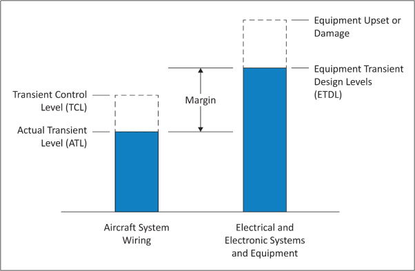
3. Typically, the applicant should specify the ETDLs prior to aircraft certification lightning tests or analyses to determine the aircraft ATLs. Therefore, the expected aircraft transients must be based upon results of lightning tests on existing aircraft, engineering analyses, or knowledgeable estimates. These expected aircraft lightning transient levels are termed Transient Control Levels (TCLs). The TCLs voltage and current amplitudes and waveforms should be specified based upon the expected lightning transients that would be generated on wiring in specific areas of the aircraft. The TCLs should be equal to or greater than the maximum expected aircraft ATLs. The TCLs for a specific wire bundle depend on the configuration of the aircraft, the wire bundle, and the wire bundle installation. The aircraft lightning protection should be designed to meet the specified TCLs.
h. Verify compliance with the requirements
1. The applicant should demonstrate that the systems comply with the applicable requirements of CS 23.1306, CS 25.1316, CS 27.1316, or CS 29.1316.
2. The applicant should demonstrate that the ETDLs exceed the ATLs by the margin established in their certification plan.
3. Verification may be accomplished by tests, analyses, or by demonstrating similarity with previously certified aircraft and systems. The certification process for Level A systems is contained in paragraph 8. The certification process for Level B and C systems is contained in paragraph 9.
4. The applicant should submit their certification plan in the early stages of the programme to the Agency for review. Experience shows that, particularly with aircraft using new technology or those that have complex systems, early agreement on the certification plan benefits both the applicant and the Agency. The plan should define acceptable ways to resolve critical issues during the certification process. Analyses and test results during the certification process may warrant modifications to the design or verification methods. When significant changes are necessary, the certification plan should be updated accordingly. The plan may include the items listed in Table 2.
i. Take corrective measures
If tests and analyses show that the system did not meet the pass/fail criteria, review the aircraft, installation or system design and improve protection against lightning.
Table 2 — Items recommended for a lightning certification plan
|
Item |
Discussion |
|
Description of systems |
Describe the systems’ installation, including unusual or unique features; the system failure condition classifications; the operational aspects; lightning attachment zones; lightning environment; preliminary estimate of ETDLs and TCLs; and acceptable margins between ETDLs and ATLs. |
|
Description of compliance method |
Describe how to verify compliance. Typically, the verification method chosen includes similarity, analytical procedures, and tests. If using analytical procedures, describe how to verify them. (See paragraph 8.d.) |
|
Acceptance criteria |
Determine the pass/fail criteria for each system by analysing how safe the system is. During this safety analysis, assess the aircraft in its various operational states; account for the failure and disruption modes caused by the effects of lightning. |
|
Test plans |
Each test undertaken as part of the demonstration of compliance should be appropriately planned. The applicant can decide if test plans are separate documents or part of the compliance plan. Test plans should state the test sequence. |
7. EFFECTS OF TRANSIENTS
Lightning causes voltage and current transients to appear on equipment circuits. Equipment circuit impedances and configurations will determine whether lightning transients are primarily voltage or current. These transient voltages and currents can degrade system performance permanently or temporarily. The two primary types of degradation are component damage and system functional upset.
a. Component damage
This is a permanent condition in which transients alter the electrical characteristics of a circuit. Examples of devices that may be susceptible to component damage include:
1. active electronic devices, especially high-frequency transistors, integrated circuits, microwave diodes, and power supply components;
2. passive electrical and electronic components, especially those of very low power or voltage rating;
3. electro-explosive devices, such as squibs and detonators;
4. electromechanical devices, such as indicators, actuators, relays, and motors; and
5. insulating materials (for example, insulating materials in printed circuit boards and connectors) and electrical connections that can burn or melt.
b. System functional upset
1. Functional upset is mainly a system problem caused by electrical transients. It may permanently or momentarily upset a signal, circuit, or a system component, which can adversely affect system performance enough to compromise flight safety. A functional upset is a change in digital or analogue state that may or may not require manual reset. In general, functional upset depends on circuit design and operating voltages, signal characteristics and timing, and system and software configuration.
2. Systems or devices that may be susceptible to functional upset include computers and data/signal processing systems; electronic engine and flight controls; and power generating and distribution systems.
8. LEVEL A SYSTEM LIGHTNING CERTIFICATION
Figure 2 illustrates a process that the applicant can use to demonstrate that their Level A system complies with CS 23.1306, CS 25.1316, CS 27.1316, and CS 29.1316.
a. Identify Level A systems Level A systems should be identified as described in paragraph 6.c. The detailed system performance pass/fail criteria should be defined. The Agency should concur on this criterion before the applicant begins testing or analysing their Level A system. Specific equipment, components, sensors, power systems and wiring associated with each Level A system should be identified in order to perform the ETDL verification mentioned in paragraphs 8.g and 8.h.
Figure 2 — Typical compliance process for Level A systems
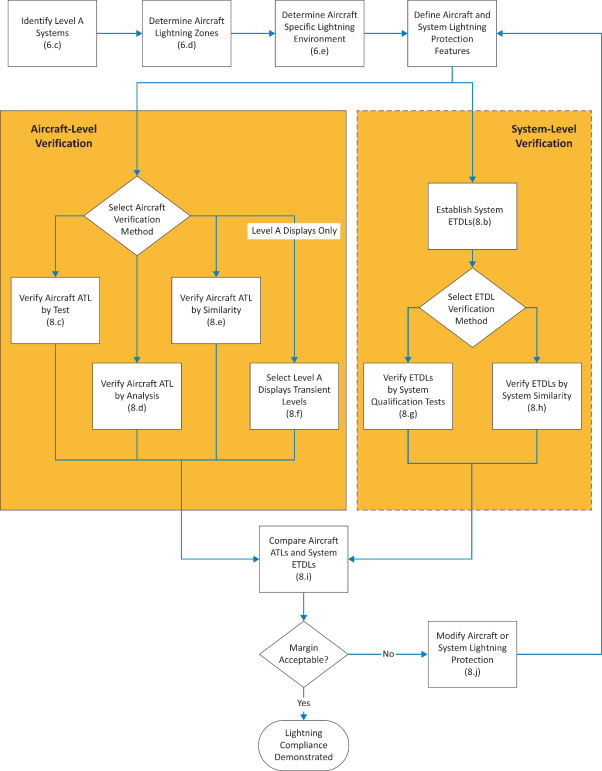
Note: Numbers in parentheses refer to sections in this AMC.
b. Establish the system’s ETDLs
Establish the aircraft system’s ETDLs from an evaluation of expected lightning transient amplitudes and waveforms for the system installation, structure and wiring configuration on a specific aircraft. ETDLs that exceed the ATLs by an acceptable margin should be established. In general, the ETDLs for equipment in a complex system will not be the same for all wire bundles connecting them to other equipment in the system. The applicant may use results of lightning tests on existing similar aircraft, engineering analyses, or knowledgeable estimates to establish the appropriate system’s ETDLs. While specific aircraft configurations and system installations may lead to ETDLs that have amplitudes and waveforms different than those defined in EUROCAE ED-14G, Section 22, ETDLs are often specified using the information from Section 22. The ETDLs must exceed the ATLs by an acceptable margin.
c. Determine the ATLs using aircraft tests
See SAE ARP 5415A, User’s Manual for Certification of Aircraft Electrical/Electronic Systems Against the Indirect Effects of Lightning, and EUROCAE ED-105A for guidance on how to determine the ATLs.
d. Determine the ATLs using analysis
See SAE ARP 5415A for guidance on how to analyse aircraft to determine the ATLs. Acceptance of the analysis method choosen will depend on the accuracy of the method. The applicant should confirm their analysis method accuracy using experimental data, and gain agreement of their analysis approach from the Agency.
e. Determine the ATLs using similarity
1. Theuse of similarity to determine the ATLs may be used when:
a. there are only minor differences between the previously certified aircraft and system installation and the aircraft and system installation to be certified; and
b. there is no unresolved in-service history of problems related to lightning strikes to the previously certified aircraft.
2. If significant differences are found that will affect the aircraft ATLs, the applicant should perform more tests and analyses to resolve the open issues.
3. To use similarity, the applicant should assess the aircraft, wiring, and system installation differences that can adversely affect the system’s susceptibility. When assessing a new installation, consider the differences affecting the internal lightning environment of the aircraft and its effects on the system. The assessment should cover:
a. aircraft type, equipment locations, airframe construction, structural materials, and apertures that could affect attenuation of the external lightning environment;
b. system wiring size, length, and routing; wire types (whether parallel or twisted wires), connectors, wire shields, and shield terminations;
c. lightning protection devices such as transient suppressors and lightning arrestors; and
d. grounding and bonding.
4. Similarity cannot be used for a new aircraft design with new systems.
f. Determine the transient levels using ED-14G, Section 22, Guidance for Level A displays only
1. The applicant may select ETDLs for their Level A display system using guidance in this section, without specific aircraft test or analysis. Level A displays involve functions for which the pilot will be in the loop through pilot–system information exchange. Level A display systems typically include the displays; symbol generators; data concentrators; sensors (such as attitude, air data, and heading sensors); interconnecting wiring; and associated control panels.
2. This approach should not be used for other Level A systems, such as control systems, because failures and malfunctions of those systems can more directly and abruptly contribute to a catastrophic failure event than display system failures and malfunctions. Therefore, other Level A systems require a more rigorous lightning transient compliance verification programme.
3. Information in Table 3 should be used to evaluate aircraft and system installation features in order to select the appropriate ETDLs for the system. Table 3 defines test levels for ETDLs, based on EUROCAE ED-14G, Section 22, Tables 22-2 and 22-3. The applicant should provide the Agency with a description of their aircraft and display system installation features and compare these to the information in Table 3 to substantiate the ETDL selected for their aircraft and Level A display system installation. When selecting ETDLs using guidance provided in Table 3, an acceptable margin between the anticipated ATLs for display system installations is incorporated in the selected ETDLs.
Table 3 — Equipment transient design levels — Level A displays
|
EUROCAE ED-14G Section 22 Level |
Display system installation location |
|
Level 5 |
Use this level when the equipment under consideration, its associated wire bundles, or other components connected by wiring to the equipment are in aircraft areas exposed to very severe lightning transients. These areas are: — areas with composite materials whose shielding is not very effective; — areas where there is no guarantee of structural bonding; and — other open areas where there is little shielding. The applicant can also use this level to cover a broad range of installations. The applicant may need higher ETDLs when there are high current density regions on mixed conductivity structures (such as wing tips, engine nacelle fin, etc.) because the system wiring may divert some of the lightning current. If the applicant is the system designer, measures should be applied to reduce the need for higher ETDLs. |
|
Level 4 |
Use this level when the equipment under consideration, its associated wire bundles, or other components connected by wiring to the equipment are in aircraft areas exposed to severe lightning transients. These areas are defined as outside the fuselage (such as wings, fairings, wheel wells, pylons, control surfaces, etc.). |
|
Level 3 |
Use this level when the equipment under consideration, its associated wire bundles, and other components connected by wiring to the equipment are entirely in aircraft areas with moderate lightning transients. We define these areas as the inside metal aircraft structure or composite aircraft structure whose shielding without improvements is as effective as metal aircraft structure. Examples of such areas are avionics bays not enclosed by bulkheads, cockpit areas, and locations with large apertures (that is, doors without electromagnetic interference (EMI) gaskets, windows, access panels, etc.). Current-carrying conductors in these areas (such as hydraulic tubing, control cables, wire bundles, metal wire trays, etc.) are not necessarily electrically grounded at bulkheads. When few wires exit the areas, either use a higher level (that is, Level 4 or 5) for these wires or offer more protection for these wires. |
|
Level 2 |
Use this level when the equipment under consideration, its associated wire bundles, and other components connected by wiring to the equipment are entirely in partially protected areas. We define these areas as the inside of a metallic or composite aircraft structure whose shielding is as effective as metal aircraft structure, if you take measures to reduce the lightning coupling to wires. Wire bundles in these areas pass through bulkheads, and have shields that end at the bulkhead connector. When a few wires exit these areas, use either a higher level (that is, Level 3 or 4) or provide more protection for these wires. Install wire bundles close to the ground plane to take advantage of other inherent shielding from metallic structures. Current-carrying conductors (such as hydraulic tubing, control cables, metal wire trays, etc.) are electrically grounded at all bulkheads. |
|
Level 1 |
Use this level when the equipment under consideration, its associated wire bundles, and other components connected by wiring to the equipment are entirely in well-protected aircraft areas. We define these areas as electromagnetically enclosed. |
g. Verify the system’s ETDLs using system qualification tests
1. The applicant should identify the equipment, components, sensors, power systems, and wiring associated with the Level A system undergoing ETDL verification tests, specifically considering the system functions whose failures have catastrophic consequences. For complex Level A systems, the system configuration may include redundant equipment, multiple power sources, multiple sensors and actuators, and complex wire bundles. Define the system configuration used for the ETDL verification tests. The applicant should obtain an EASA approval of their system configuration for ETDL verification tests.
2. Verify the ETDLs using single stroke, multiple stroke, and multiple burst tests on the system wire bundles. Use waveform sets and test levels for the defined ETDLs. Demonstrate that the system operates within the defined pass/fail criteria during these tests. No equipment damage should occur during these system tests or during single stroke pin injection tests using the defined ETDLs. EUROCAE ED-14G, Section 22, provides acceptable test procedures and waveform set definitions. In addition, EUROCAE ED-105A provides acceptable test methods for complex and integrated systems.
3. Evaluate any system effects observed during the qualification tests to ensure they do not adversely affect the system’s continued performance. The Level A system performance should be evaluated for functions for which failures or malfunctions would prevent the continued safe flight and landing of the aircraft. Other functions performed by the system for which failures or malfunctions would reduce the capability of the aircraft or the ability of the flight crew to respond to an adverse operating condition should be evaluated using the guidance in Chapter 10. The applicant should obtain an EASA approval of their evaluation.
h. Verify the system’s ETDLs using existing system data (similarity)
1. The applicant may base their ETDL verification on similarity to previously certified systems without performing more tests. This may be done when:
a. there are only minor differences between the previously certified system and installation and the system and installation to be certified;
b. there are no unresolved in-service system problems related to lightning strikes on the previously certified system; and
c. the previously certified system ETDLs were verified by qualification tests.
2. To use similarity to previously certified systems, the applicant should assess the differences between the previously certified system and installation and the system and installation to be certified that can adversely affect the system’s susceptibility. The assessment should cover:
a. system interface circuits;
b. wire size, routing, arrangement (parallel or twisted wires), connector types, wire shields, and shield terminations;
c. lightning protection devices such as transient suppressors and lightning arrestors;
d. grounding and bonding; and
e. system software, firmware, and hardware.
3. If the applicant is unsure how the differences will affect the systems and installations, they should perform more tests and analyses to resolve the open issues.
4. The applicant should assess every system, even if it uses equipment and installation techniques that have a previous certification approval.
5. The use of similarity should not be used for a new aircraft design with new systems.
i. Verify compliance with the requirements
The applicant should compare the verified system ETDLs with the aircraft ATLs and determine if an acceptable margin exists between the ETDLs and the ATLs. Margins account for uncertainty in the verification method. As confidence in the verification method increases, the margin can decrease. An ETDL exceeding the ATL by a factor of two is an acceptable margin for Level A systems, if this margin is verified by aircraft test or by analysis supported by aircraft tests. For Level A display systems where the ETDLs are determined using guidance provided in Table 3, an acceptable margin is already incorporated in the selected ETDLs. For other verification methods, the margin should be agreed upon with the Agency.
j. Take corrective measures
1. When a system fails to meet the certification requirements, corrective actions should be selected. Any changes or modifications made to the aircraft, system installation or the equipment may require more testing and analysis.
2. To meet the certification requirements, the applicant may need to repeat system qualification testing, or aircraft testing and analysis (in whole or in part). This may include modification to the system or installation to get certification. The applicant should review these changes or modifications with the Agency to determine if they are significant. If these changes or modifications are significant, the applicant should update their lightning certification plan accordingly. The updated certification plan should be resubmitted to the Agency for review.
9. LEVEL B AND C SYSTEM LIGHTNING CERTIFICATION
a. Identify Level B and C systems
1. The applicant should identify their Level B and C systems as described in paragraph 6.c.
2. The applicant should define the detailed system performance pass/fail criteria. They should obtain the Agency’s concurrence on this criterion before starting tests or analyses of Level B and C systems.
3. Figure 3 illustrates a process the applicant can use to demonstrate that their Level B and C systems comply with the CS requirements.
Figure 3 — Typical compliance process for Level B and C systems
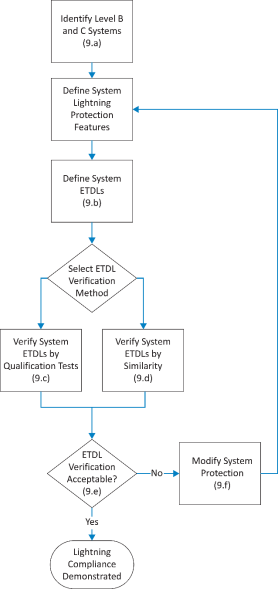
Note: Numbers in parentheses refer to sections in this AMC.
b. Establish the ETDLs
1. ATLs determined during aircraft tests or analyses performed for Level A systems to establish the appropriate ETDLs for Level B and C systems.
2. Alternatively, the applicant may use the definitions in EUROCAE ED-14G, Section 22, to select the appropriate ETDLS for their Level B and C systems. The following should be considered when selecting an appropriate level:
a. Use EUROCAE ED-14G, Section 22, Level 3 for most Level B systems.
b. For Level B systems and associated wiring installed in aircraft areas with more severe lightning transients, use EUROCAE ED-14G, Section 22, Level 4 or 5 as appropriate to the environment. Examples of aircraft areas with more severe lightning transients are those external to the fuselage, areas with composite structures showing poor shielding effectiveness, and other open areas.
c. Use EUROCAE ED-14G, Section 22, Level 2 for most Level C systems.
d. For Level C systems installed in aircraft areas with more severe lightning transients, use EUROCAE ED-14G, Section 22, Level 3. Examples of aircraft areas with more severe lightning transients are those external to the fuselage, areas with composite structures showing poor shielding effectiveness, and other open areas.
e. The applicant should provide the Agency with a description of their aircraft and system installation features to substantiate the EUROCAE ED-14G, Section 22, levels selected for their system.
c. Verify the system’s ETDLs using equipment qualification tests
1. Equipment qualification tests should be performed using the selected test levels and single stroke, multiple stroke, and multiple burst waveform sets. It should be demonstrated that the equipment operates within the defined pass/fail criteria during these tests. No equipment damage should occur during these equipment qualification tests or during single stroke pin injection tests using the defined ETDLs. EUROCAE ED-14G, Section 22, provides acceptable test procedures and waveform set definitions.
2. Any equipment effects observed during the qualification tests should be evaluated to ensure that they do not adversely affect the system’s continued performance. The applicant should obtain the Agency’s approval of their evaluation.
3. Multiple stroke and multiple burst testing is not required if an analysis shows that the equipment is not susceptible to upset, or that the equipment may be susceptible to upset but a reset capability exists so that the system recovers in a timely manner.
d. Verify the system’s ETDLs using existing equipment data (similarity)
1. ETDLs may be verified by similarity to previously certified systems without performing more tests. The applicant may do this when:
a. there are only minor differences between the previously certified system and installation and the system and installation to be certified;
b. there are no unresolved in-service system problems related to lightning strikes on the previously certified system; and
c. the previously certified system ETDLs were verified by qualification tests.
2. The assessment should cover:
a. equipment interface circuits;
b. wire size, routing, arrangement (parallel or twisted wires), connector types, wire shields, and shield terminations;
c. lightning protection devices such as transient suppressors and lightning arrestors;
d. grounding and bonding; and
e. equipment software, firmware, and hardware.
3. If significant differences are found that will affect the systems and installations, the applicant should perform more tests and analyses to resolve the open issues.
e. Verify compliance with the requirements
The applicant should demonstrate that the Level B and C systems meet their defined acceptance criteria during the qualification tests at the selected system ETDLs.
f. Take corrective measures
When a system fails to meet the certification requirements, the applicant should decide on corrective actions. If they change or modify the system or installation, equipment qualification testing may need to be repeated. The applicant should review these changes or modifications with the Agency to determine if they are significant. If these changes or modifications are significant, the applicant should update their lightning certification plan accordingly. The updated certification plan should be resubmitted to the Agency for review.
10. MAINTENANCE AND SURVEILLANCE
a. The applicant should identify the minimum maintenance required for the aircraft electrical and electronic system lightning protection in the Instructions for Continued Airworthiness (ICA). The applicant should define the requirements for periodic and conditional maintenance and surveillance of lightning protection devices or features to ensure acceptable protection performance while the aircraft is in service. Avoid using devices or features that may degrade with time because of corrosion, fretting, flexing cycles, or other causes. Alternatively, identify when to inspect or replace these devices.
b. The applicant should define the inspection techniques and intervals needed to ensure that the aircraft and system lightning protection remains effective in service. Also, identify built-in test equipment, resistance measurements, continuity checks of the entire system, or other means to determine the system’s integrity periodically and conditionally.
c. See SAE ARP 5415A for more information on aircraft lightning protection maintenance and surveillance.
[Amdt 20/13]
Appendix 1 to AMC 20-136 Definitions and acronyms
ED Decision 2015/017/R
a. Definitions
Actual Transient Level (ATL): The level of transient voltage or current that appears at the equipment interface circuits because of the external environment. This level may be less than or equal to the transient control level, but should not be greater.
Aperture: An electromagnetically transparent opening.
Attachment point: A point where the lightning flash contacts the aircraft.
Component damage: A condition in which transients permanently alter the electrical characteristics of a circuit. Because of this, the component can no longer perform to its specifications.
Continued safe flight and landing: The aircraft can safely abort or continue a take-off, or continue controlled flight and landing, possibly using emergency procedures. The aircraft must do this without requiring exceptional pilot skill or strength. Some aircraft damage may occur because of the failure condition or on landing. For large aeroplanes, the pilot must be able to land safely at a suitable airport.
For CS-23 aeroplanes, it is not necessary to land at an airport. For rotorcraft, the rotorcraft must continue to cope with adverse operating conditions, and the pilot must be able to land safely at a suitable site.
Direct effects: Physical damage to the aircraft or electrical and electronic systems. Direct attachment of lightning to the system’s hardware or components causes the damage. Examples of direct effects include tearing, bending, burning, vaporisation, or blasting of aircraft surfaces and structures, and damage to electrical and electronic systems.
Equipment Component of an electrical or electronic system with interconnecting electrical conductors.
Equipment Transient Design Level (ETDL): The peak amplitude of transients to which equipment is qualified.
External environment: The natural lightning environment, outside the aircraft, for design and certification purposes. See EUROCAE ED-84A, which reference documents that provide additional guidance on aircraft lightning environment and related waveforms.
Indirect effects: Electrical transients induced by lightning in aircraft electrical or electronic circuits.
Internal environment: The potential fields and structural voltages inside the aircraft produced by the external environment.
Lightning flash: The total lightning event. It may occur in a cloud, among clouds, or between a cloud and the ground. It can consist of one or more return strokes, plus intermediate or continuing currents.
Lightning strike: Attachment of the lightning flash to the aircraft.
Lightning strike zones: Aircraft surface areas and structures that are susceptible to lightning attachment, dwell time, and current conduction. See EUROCAE ED-91, which references documents that provide additional guidance on aircraft lightning zoning.
Lightning stroke (return stroke): A lightning current surge that occurs when the lightning leader (the initial current charge) makes contact with the ground or another charge centre. A charge centre is an area of high potential of opposite charge.
Margin: The difference between the equipment transient design levels and the actual transient level.
Multiple burst: A randomly spaced series of bursts of short duration, low amplitude current pulses, with each pulse characterised by rapidly changing currents. These bursts may result as the lightning leader progresses or branches, and are associated with the cloud-to-cloud and intra-cloud flashes. The multiple bursts appear most intense when the initial leader attaches to the aircraft. See EUROCAE ED-84A.
Multiple stroke: Two or more lightning return strokes during a single lightning flash. See EUROCAE ED-84A.
Transient Control Level (TCL): The maximum allowable level of transients that appear at the equipment interface circuits because of the defined external environment.
b. Acronyms
AC: Advisory Circular
AMC: Acceptable Means of Compliance
ARP: Aerospace Recommended Practice
ATL: Actual Transient Level
CS: Certification Specification
ETDL: Equipment Transient Design Level
EASA: European Aviation Safety Agency
EUROCAE: European Organization for Civil Aviation Equipment
FAA: Federal Aviation Administration
ICA: Instructions for Continued Airworthiness
TCL: Transient Control Level
[Amdt 20/13]