
AMC 20-20A Continuing structural integrity programme
ED Decision 2020/023/R
1. PURPOSE
(a) This acceptable means of compliance (AMC) provides guidance to type certificate holders (TCHs), supplemental type certificate holders (STCHs), repair approval holders, maintenance organisations, operators and competent authorities for developing continuing structural integrity programmes to ensure safe operation of ageing aircraft throughout their operational lives.
This AMC is primarily aimed at large aeroplanes; however, this material is also applicable to other aircraft types for operators and TCHs wishing to develop robust continuing structural integrity programmes.
(b) It is particularly important for the TCHs of ageing aircraft to ensure that their continuing structural integrity programmes remain valid throughout the operational life of the aircraft.
(c) The means of compliance described in this document provides guidance to supplement the engineering and operational judgement that must form the basis of any compliance findings relative to continuing structural integrity programmes.
(d) Like all acceptable means of compliance material, this AMC is not in itself mandatory, and does not constitute a requirement. It describes an acceptable means, but not the only means, for showing compliance with the requirements. While these guidelines are not mandatory, they are derived from extensive industry experience in determining compliance with the relevant requirements.
(e) This AMC also supports compliance with the ageing structural integrity requirements in Annex I (Part-26) to Regulation (EU) 2015/640, as introduced by Regulation (EU) 2020/1159 (ref. points 26.300 through 26.370 and the associated CS-26 paragraphs) including limits of validity (LOVs), WFD evaluation, damage tolerance for repairs and modifications, and processes for ensuring the continued validity of the continuing structural integrity programme.
2. RELATED REGULATIONS AND DOCUMENTS
(a) Implementing Rules and Certification Specifications:
Point 21.A.61 Instructions for continued airworthiness
Point 21.A.120 Instructions for continued airworthiness
Points 26.300 through 26.334 applicable to DAHs
Point 21.A.433 Repair design
Point 26.370 Rules applicable to operators
Point M.A.302 Maintenance programme
CS 25.571 Damage tolerance and fatigue evaluation of structure
CS 25.1529 Instructions for continued airworthiness
CS 26.300 through 26.370 Means of compliance for Part-26 ageing aeroplane structures requirements
(b) EASA AMC and FAA Advisory Circulars
AMC 25.571 Damage tolerance and fatigue evaluation of structure
AC 91-81 Management Programs for Airplanes with Demonstrated Risk of Catastrophic Failure Due to Fatigue, 29 April 2008, FAA
AC 91-56B Continuing Structural Integrity for Airplanes, 7 March 2008, FAA
AC 120-73 Damage Tolerance Assessment of Repairs to Pressurised Fuselages, FAA, 14 December 2000
AC 120-93 Damage Tolerance Inspections for Repairs and Alterations
AC 120-104 Establishing and Implementing Limit of Validity to Prevent Widespread Fatigue Damage
AC 25.1529-1A Instructions for Continued Airworthiness of Structural Repairs on Transport Airplanes, FAA, 20 November 2007
(c) Related documents
— ‘Recommendations for Regulatory Action to Prevent Widespread Fatigue Damage in the Commercial Aeroplane Fleet’, Revision A, dated June 29, 1999 [A report of the Airworthiness Assurance Working Group for the Aviation Rulemaking Advisory Committee Transport Aircraft and Engine Issues].
— AAWG Final Report on Continued Airworthiness of Structural Repairs, Dec 1996.
— ATA report 51-93-01 structural maintenance programme guidelines for continuing airworthiness, May 1993.
— AAWG Report on Structures Task Group Guidelines, Rev 1 June 1996.
— AAWG Report: Recommendations concerning ARAC taskings FR Doc 04-10816 Ref.: Aging Airplane safety final rule. 14 CFR 121.370a and 129.16.
— Federal Aviation Administration 14 CFR Parts 26, 121, and 129 [Docket No FAA‑2005-21693; Amendment Nos 26–1, 121–337, 129–44] Damage Tolerance Data for Repairs and Alterations Final Rule.
— Federal Aviation Administration 14 CFR Parts 25, 26, 121, and 129 [Docket No FAA‑2006-24281; Amendment Nos 25–132, 26–5, 121–351, 129–48] Aging Airplane Program: Widespread Fatigue Damage Final Rule.
3. BACKGROUND
Service experience has shown there is a need to have continually updated knowledge on the structural integrity of aircraft, especially as they become older, to ensure they continue to meet the level of safety intended by the certification requirements. The continued structural integrity of aircraft is of concern because factors such as fatigue cracking and corrosion are time‑dependent, and our knowledge about them can best be assessed based on real-time operational experience and the use of the most modern tools of analysis and testing.
In April 1988, a high-cycle transport aeroplane en-route from Hilo to Honolulu, Hawaii, suffered major structural damage to its pressurised fuselage during flight. This accident was attributed in part to the age of the aeroplane involved. The economic benefit of operating certain older technology aeroplanes resulted in the operation of many such aeroplanes beyond their previously expected retirement age. Because of the problems revealed by the accident in Hawaii and the continued operation of older aircraft, both the competent authorities and industry generally agreed that increased attention needed to be focused on the ageing fleet and on maintaining its continued operational safety.
In June 1988, the FAA sponsored a conference on ageing aircraft. As a result of that conference, an ageing aircraft task force was established in August 1988 as a sub-group of the FAA’s Research, Engineering, and Development Advisory Committee, representing the interests of the aircraft operators, aircraft manufacturers, regulatory authorities, and other aviation representatives. The task force, then known as the Airworthiness Assurance Task Force (AATF), set forth five major elements of a programme for keeping the ageing fleet safe. For each aeroplane model in the ageing transport fleet, these elements consisted of the following:
(a) Select service bulletins describing modifications and inspections necessary to maintain structural integrity;
(b) Develop inspection and prevention programmes to address corrosion;
(c) Develop generic structural maintenance programme guidelines for ageing aeroplanes;
(d) Review and update the supplemental structural inspection documents (SSIDs) which describe inspection programmes to detect fatigue cracking; and
(e) Assess the damage tolerance of structural repairs.
Subsequent to these five major elements being identified, it was recognised that an additional factor in the Aloha accident was widespread fatigue cracking. Regulatory and industry experts agreed that, as the transport aircraft fleet continues to age, eventually widespread fatigue damage (WFD) is inevitable. Structures Task Groups sponsored by the Task Force were assigned the task of developing these elements into usable programmes. The Task Force was later re‑established as the AAWG of the ARAC. Although there was JAA membership and European operators and industry representatives participated in the AAWG, recommendations for action focussed on FAA operational rules which are not applicable in Europe. It was therefore decided to establish the EAAWG on this subject to implement ageing aircraft activities in Europe, not only for the initial ‘AATF eleven’ aeroplanes, but also other old aircraft and more recently certified ones. EAAWG recommendations followed, leading to the development of guidance material for TCHs and operators, and proposals to develop Sub-part M of JAR OPS. The subsequent establishment of the Agency and new EU regulations led to the current format of Part-M for continuing airworthiness, the associated maintenance programme requirements and to the inclusion of ageing aircraft structures programmes in AMC Part M (M.A.302). AMC 20-20 supported this process and set out means by which TCHs and operators could develop and implement ageing aircraft structures programmes.
This AMC supports DAH and operator compliance with the requirements introduced by Commission Implementing Regulation (EU) 2020/1159 on ageing aeroplane structures, amending Regulation (EU) 2015/640 (Part-26), and the associated CS-26 specifications. The Regulation includes requirements for specific DAHs to perform damage tolerance and other evaluations of existing airframe structure, develop certain data and ICA if they have not already done so, and make it available to operators. Furthermore, operators, in addition to implementing these new ICA as envisaged under Part-M, are required by Part-26 to ensure that approved damage-tolerance-based inspections are obtained and implemented on all repairs and modifications affecting the FCS on aeroplanes certified for 30 passengers or more or for 7 500 lb or more payload.
Points 26.300 through 26.370 of Part-26 provide requirements for a complete retroactively applicable continuing structural integrity programme for specific categories of large aeroplanes. The principal means of compliance with those regulations may be found in CS-26, which, in turn, refers to this AMC.
4. DEFINITIONS AND ACRONYMS
(a) For the purposes of this AMC, the following definitions apply:
— Airworthiness limitation section (ALS) means a section in the instructions for continued airworthiness, as required by points 21.A.61, 21.A.107 and 21.A.120A of Annex I (Part 21) to Regulation (EU) No 748/2012, which contains airworthiness limitations that set out each mandatory replacement time, inspection interval and related inspection procedure.
— Baseline structure refers to the structure that is designed under the type certificate for that aeroplane model (that is, the ‘as delivered aeroplane model configuration’).
— Corrosion prevention and control programme (CPCP) is a document reflecting a systematic approach to prevent and to control corrosion in an aeroplane’s primary structure, consisting of basic corrosion tasks, including inspections, areas subject to those tasks, defined corrosion levels and compliance times (implementation thresholds and repeat intervals). A baseline CPCP is established by the type certificate holder, which can be adapted by operators to create a CPCP in their maintenance programme specific to their operations.
— Damage tolerance (DT) is the attribute of the structure that permits it to retain its required residual strength without detrimental structural deformation for a period of use after the structure has sustained a given level of fatigue, corrosion, and accidental or discrete source damage.
— Design approval holder (DAH) is the holder of any design approval, including type certificate, supplemental type certificate or earlier equivalent, or repair approval.
— Damage tolerance data is the combination of DTE documentation and DTI.
— Damage tolerance evaluation (DTE) is a process that leads to the determination of the maintenance actions necessary to detect or preclude fatigue cracking that could contribute to a catastrophic failure. When applied to repairs and changes, a DTE includes the evaluation of the repair or change and the fatigue-critical structure affected by the repair or change.
— Damage tolerance inspection (DTI) is a documented inspection requirement or other maintenance action developed by holders of design approvals or third parties as a result of a damage tolerance evaluation. A DTI includes the areas to be inspected, the inspection method, the inspection procedures (including the sequential inspection steps and acceptance and rejection criteria), the inspection threshold and any repetitive intervals associated with those inspections. DTIs may also specify maintenance actions such as replacement, repair or modification.
— Design service goal (DSG) is the period of time (in flight cycles or flight hours, or both) established at design and/or certification during which the aeroplane structure is expected to be reasonably free from significant cracking.
— Existing design changes or repairs are changes and repairs which are to be approved before the date of entry into force of this rule.
— Fatigue-critical alteration structure (FCAS) is equivalent to fatigue-critical modified structure.
— Fatigue-critical baseline structure (FCBS) is the baseline structure of an aeroplane that is classified by the type certificate holder as a fatigue-critical structure.
— Fatigue-critical modified structure (FCMS) means any fatigue-critical structure of an aeroplane introduced or affected by a change to its type design and that is not already listed as part of the fatigue-critical baseline structure.
— Fatigue-critical structure (FCS) is a structure of an aeroplane that is susceptible to fatigue cracking that could lead to a catastrophic failure of the aircraft. For the purposes of this AMC, FCS refers to the same class of structure that would need to be assessed for compliance with JAR 25.571 Change 7 or 14CFR § 25.571(a) at Amendment 25-45, or later. The term ‘FCS’ may refer to fatigue-critical baseline structure, fatigue‑critical modified structure, or both.
— Inspection start point (ISP) is the point in time when special inspections of the fleet are initiated due to a specific probability of having an MSD/MED condition.
— Future design changes and repairs are changes and repairs which are to be approved on or after the date of entry into force of this rule.
— Limit of validity (LOV) (of the engineering data that supports the structural maintenance programme) means, in the context of the engineering data that supports the structural maintenance programme, a period of time, stated as a number of total accumulated flight cycles or flight hours or both, during which it is demonstrated that widespread fatigue damage will not occur in the aeroplane.
— Multiple-element damage (MED) is a source of widespread fatigue damage characterised by the simultaneous presence of fatigue cracks in similar adjacent structural elements.
— Multiple-site damage (MSD) is a source of widespread fatigue damage characterised by the simultaneous presence of fatigue cracks in the same structural element.
— Primary structure is structure that carries flight, ground, crash or pressurisation loads.
— Published repair data are instructions for accomplishing repairs which are published for general use in structural repair manuals and service bulletins (or equivalent types of documents).
— Repair assessment guidelines (RAGs) provide a process to establish damage tolerance inspections for repairs on the fuselage pressure boundary structure.
— Repair assessment programme (RAP) is a programme to incorporate damage‑tolerance-based inspections for repairs to the fuselage pressure boundary structure (fuselage skin, door skin, and bulkhead webs) into the operator’s maintenance and/or inspection programme.
— Repair evaluation guidelines (REGs) are established by the type certificate holder and guide operators to establish damage tolerance inspections for repairs that affect fatigue-critical structure to ensure the continued structural integrity of all relevant repairs.
— Structural modification point (SMP) is the point in time when a structural area must be modified to preclude WFD.
— Widespread fatigue damage (WFD) means the simultaneous presence of cracks at multiple locations in the structure of an aeroplane that are of such size and number that the structure will no longer meet the fail-safe strength or residual strength used for the certification of that structure.
(b) The following list defines the acronyms that are used throughout this AMC:
|
AAWG |
Airworthiness Assurance Working Group |
|
AC |
advisory circular |
|
AD |
airworthiness directive |
|
ALS |
airworthiness limitations section |
|
AMC |
acceptable means of compliance |
|
ARAC |
Aviation Rulemaking Advisory Committee |
|
BZI |
baseline zonal inspection |
|
CAW |
continuing airworthiness |
|
CPCP |
corrosion prevention and control programme |
|
CS |
certification specification |
|
DAH |
design approval holder |
|
DSD |
discrete source damage |
|
DSG |
design service goal |
|
DT |
damage tolerance |
|
DTE |
damage tolerance evaluation |
|
DTI |
damage tolerance inspection |
|
EAAWG |
European Ageing Aircraft Working Group |
|
EASA |
European Union Aviation Safety Agency |
|
ESG |
extended service goal |
|
FAA |
Federal Aviation Administration |
|
FAR |
Federal Aviation Regulation |
|
FCBS |
fatigue-critical baseline structure |
|
FCS |
fatigue-critical structure |
|
ICA |
instructions for continued airworthiness |
|
ISP |
inspection start point |
|
JAA |
Joint Aviation Authorities |
|
JAR |
joint aviation regulation |
|
LOV |
limit of validity |
|
MED |
multiple-element damage |
|
MRB |
Maintenance Review Board |
|
MSD |
multiple-site damage |
|
MTOM |
maximum take-off mass |
|
MSG |
Maintenance Steering Group |
|
NAA |
national aviation authority |
|
NDI |
non-destructive inspection |
|
NTSB |
National Transportation Safety Board |
|
PSE |
principal structural element |
|
RAP |
repairs assessment programme |
|
REGs |
repair evaluation guidelines |
|
SB |
service bulletin |
|
SMP |
structural modification point |
|
SRM |
structural repair manual |
|
SSID |
supplemental structural inspection document |
|
SSIP |
supplemental structural inspection programme |
|
STG |
structural task group |
|
STCH |
supplemental type certificate holder |
|
TCH |
type certificate holder |
|
WFD |
widespread fatigue damage |
5. CONTINUING STRUCTURAL INTEGRITY PROGRAMME AND WAY OF WORKING
(a) General
The programmes and processes described in this and the subsequent paragraphs of this AMC are all part of an acceptable process to provide a continuing structural integrity programme that precludes unsafe levels of cracking.
DAHs and operators are expected to work together to ensure that their continuing structural integrity programmes remain valid.
Points 26.300 through 26.309 provide retroactive requirements for TCHs to establish a continuing structural integrity programme for the type design of large aeroplanes. Aeroplanes certified in compliance with CS-25 Amendment 19 or later have acceptable structural maintenance programmes. Nonetheless, in both cases, there is a need to ensure that the continuing structural integrity programme remains valid throughout the operational life of the aeroplane.
(b) Maintaining the validity of the continuing structural integrity programme
Point 26.305 requires TCHs to establish a process that ensures that the continuing structural integrity programme remains valid throughout the operational life of the aeroplane, considering service experience and current operations. CS 26.305 (a) and (c) describe the core content of the process required as the means of compliance with point 26.305, and further details are provided in Appendix 5 to this AMC. The intent is for the TCHs of large transport aeroplanes to monitor the continued validity of the assumptions upon which the maintenance programme is based, and to ensure that unsafe levels of fatigue cracking or other structural deterioration will be precluded in service. It should be noted that this requirement applies to all structure whose failure could contribute to a catastrophic failure, and it is not limited to metallic structures or fatigue cracking, but should also encompass composite and hybrid structures.
Typically, large aeroplanes are utilised in well-understood commercial transport scenarios for which conservative or more rational and well-bounded assumptions can be made at the time of certification or when the continuing structural integrity programme is developed. Obvious changes to usage should be addressed for their impact on fatigue and damage tolerance when they occur. In particular, aeroplanes used for conducting surveys, VIP operations, firefighting or other special operations should be considered on a case-by-case basis.
Furthermore, as part of this process, the assumptions made for fatigue, accidental and environmental damage scenarios during certification should, on a regular basis, be validated against service experience to see whether they remain applicable.
The monitoring of operational usage is best achieved in cooperation with the operators, combined with fleet leader sampling inspection programmes. Where data does not correspond to the original certification assumptions, its potential impact on all ageing aeroplane structural programmes and CAW in general must be considered. The degree of impact that a change of usage may have is dependent on the level of conservatism in the selection of the original usage spectrum. It is recommended to review at regular intervals the operational usage data for which a change from the original assumptions would have an impact on the validity of the content of the programme. If this is not done, it might be necessary to investigate the operational usage on each occasion of a service finding in which operational usage could be a contributing factor.
(c) Way of working
All the ageing aircraft programme elements discussed in this AMC benefit from cooperation between operators and TCHs. The use of structural task groups (STGs) has historically proved very successful in this regard, and is recommended.
On the initiative of the TCH and EASA, an STG may be formed for each aircraft model for which it is decided to put in place an ageing aircraft programme. The STG shall consist of the TCH, selected operator members and EASA representative(s). The objective of the STG is to complete all tasks covered in this AMC in relation to their respective model types, including the following:
— Develop model specific programmes,
— Define programme implementation,
— Conduct recurrent programme reviews as necessary.
It is recognised that it might not always be possible to form or to maintain an STG, due to a potential lack of resources within the operators or TCH. Furthermore, for some mature products, the programmes and their implementation may be sufficiently mature to determine that an STG is not necessary, e.g. when large numbers of aeroplanes have already reached their expected retirement age and none are going to be operated beyond that point. This point could be determined by the LOV, provided that it is not extended. In any case, the responsibilities for ensuring compliance with the applicable requirements are outlined in subparagraph (d) of this paragraph.
An acceptable way of working for STGs is described in the ‘Report on Structures Task Group Guidelines’ that was established by the AAWG with the additional clarifications provided in the following subparagraphs.
(1) Meeting scheduling
It is the responsibility of the TCH to schedule STG meetings.
(2) Reporting
The STG may make recommendations for actions via the TCH to EASA. Additionally, the STG should give periodic reports (for information only) to EASA as appropriate with the objective of maintaining a consistent approach.
(3) Recommendations and decision-making
The decision-making process described in the AAWG Report on Structures Task Group Guidelines paragraph 7 leads to recommendations for mandatory action from the TCH to EASA. In addition, it should be noted that EASA is entitled to mandate safety measures related to ageing aircraft structures, in addition to those recommended by the STG, if it finds it necessary.
(d) Responsibilities
(1) The TCH is responsible for developing the ageing aircraft structures programme for each aircraft type, detailing the actions necessary to maintain airworthiness. Other DAHs should develop programmes or actions appropriate to the modification/repair for which they hold approval, unless addressed by the TCH. All the continuing structural integrity programmes, including associated maintenance actions and DTIs, are changes to the ICA and, therefore, are subject to the Part 21 requirements for their promulgation. All DAHs will be responsible for monitoring the effectiveness of their specific programme, and for amending the programme as necessary.
(2) The operator is responsible for incorporating approved DAH actions necessary to maintain airworthiness into its aircraft-specific maintenance programmes, in accordance with Part-M (point M.A.302) and point 26.370.
(3) The competent authority of the State of registry, or the continuing airworthiness management organisation (CAMO) when it holds the approval privilege, is responsible for the approval of the aircraft maintenance programme.
(4) EASA will approve elements of ageing aircraft structures programmes developed by DAHs and may issue ADs to support implementation, where necessary, e.g. to implement applicable inspections and maintenance actions necessary to support the LOV. However, it is intended that Part-M and, where necessary, Part-26 requirements will be the usual means of implementation of ageing aircraft programmes in European registered aircraft. EASA, in conjunction with the DAH, will monitor the overall effectiveness of ageing aircraft structures programmes.
(e) Continued airworthiness and management of cracks and other damage findings in service
Point 26.305 of Part-26 requires a process to be established that ensures that the continuing structural integrity programme remains valid throughout the operational life of the aeroplane, considering service experience and current operations. One of the elements of this process is the review of new occurrences, existing damage‑tolerance‑based inspections and service bulletins (SBs), which is established in order to determine the need for mandatory changes in cases where inspections alone would not be reliable enough, or to ensure that unsafe levels of cracking are precluded.
For a new type design, the regulations include the damage tolerance approach for preventing catastrophic failures due to fatigue. The damage tolerance approach depends on directed inspection programmes to detect fatigue cracks before they reach their critical sizes.
If an inspection finds cracks in a damage-tolerant fleet, the approval holder, together with EASA, may determine that a demonstrated risk exists, and require additional airworthiness actions, including more rigorous inspection requirements or fleet-wide replacement or modification of the structure.
Cracking is a continued airworthiness issue because cracking usually reduces the strength of the structure to less than its design ultimate strength level. Service history has shown that the reliability of directed inspections is never sufficient to detect all cracks. As the number of crack reports increases, the likelihood that a number of aeroplanes in the fleet have undetected fatigue cracks also increases. Therefore, for areas where fatigue cracks are reported, the likelihood increases that a number of aeroplanes in the fleet will have strengths less than the design ultimate strength level. At some time during operation of the fleet, the likelihood that the strength of any given structure in a fleet is less than the design ultimate strength level may become unacceptably high. The loss of design ultimate strength capability should be a rare event, and EASA rarely knowingly allows the strength of aeroplanes to drop below the design ultimate strength level with any significant frequency.
Approval holders can use the damage tolerance approach to address an unsafe condition. However, it should be understood that damage-tolerance-based inspections may not provide a permanent solution, as explained above, and in cases where cracks are expected to continue to develop in the fleet, the approval holder should propose, and EASA may require, the fleet-wide replacement, modification, or removal from service of the structure.
Other than fatigue crack findings, significant environmental and accidental damage findings should also be taken into account. Initial and critical damage scenarios assumed for certification should be compared to those being reported and where there are differences, the potential airworthiness impact should be evaluated. Differences may include the pattern and extent of cracking, corrosion or accidental damage, the time at which it was discovered and the rate of growth.
More guidance on the continued airworthiness procedures for airframe structures to ensure the validity of the continuing structural integrity programme is provided in Appendix 5.
6. DAMAGE-TOLERANCE-BASED INSPECTION PROGRAMME
Aeroplanes certified to JAR 25 Change 10 or later or 14 CFR 25 Amdt 54 or later are provided with an airworthiness limitations section (ALS) that includes damage-tolerance-based inspections. Many aeroplanes certified to earlier amendments have also been provided with a DT-based ALS.
Point 26.302 of Part-26 requires TCHs for certain large transport aeroplanes to perform a damage tolerance evaluation (DTE) and establish the associated inspections and other procedures that ensure freedom from catastrophic failures due to fatigue throughout the operational life of the aeroplane. An SSID or ALS developed according to the guidance of this AMC or an SSID mandated under a current EASA AD will satisfy the requirements of point 26.302 of Part-26. In the absence of an approved damage-tolerance-based structural maintenance inspection programme, the TCH, in conjunction with operators, is expected to initiate the development of an SSIP for each aeroplane model. The role of the operator is principally to comment on the practicality of the inspections and any other procedures defined by the TCH and to implement them effectively.
The SSID or ALS should include inspection threshold, repeat interval, inspection methods and procedures. The applicable modification status, associated life limitation and types of operations for which the SSID is valid should also be identified and stated.
For aeroplanes for which a DTE is necessary in accordance with CS 25.571 or point 26.302 of Part-26, all inspections and other procedures must be provided that are anticipated to be necessary throughout the operational life of the aeroplane to prevent catastrophic failures due to fatigue. For an aircraft maintenance programme subject to an LOV under point 26.303 of Part-26 or CS 25.571, the DTE need only provide the inspections and other procedures necessary to prevent catastrophic failures up to the LOV. For other aeroplanes, it is recommended that the ALS includes an LOV or similar limitation on the applicability of the maintenance programme, otherwise the programme should be shown to address the maximum potential usage of the aeroplane based on experience with similar products or a conservative assumption. For an SSIP newly developed to meet point 26.302 of Part-26, the guidance of this AMC applies.
In addition, the inspection access, the type of damage being considered, likely damage sites and details of the resulting fatigue cracking scenario should be included as necessary to support the prescribed inspections.
As a result of a periodic review, the TCH should revise the SSID whenever additional information shows a need. The original SSID will normally be based on predictions or assumptions (from analyses, tests, and/or service experience) of failure modes, time to initial damage, frequency of damage, typically detectable damage, and the damage growth period. Consequently, a change in these factors sufficient to justify a revision would have to be substantiated by test data or additional service information. Any revision to SSID criteria and the basis for these revisions should be submitted to EASA for review and approval of both engineering and maintenance aspects.
7. DAMAGE TOLERANCE EVALUATION OF REPAIRS AND MODIFICATIONS
Early fatigue or fail-safe requirements (pre-JAR 25.571 Change 7 and 14 CFR §25.571 Amdt 45) did not necessarily provide for timely inspection of critical structure so that damaged or failed components could be dependably identified and repaired or replaced before a hazardous condition developed. This applies to modifications and repairs as well as baseline structure. Furthermore, it is known that application of later fatigue and damage tolerance requirements to repairs was not always fully implemented according to the relevant certification bases.
As such, repairs and modifications that have not been subject to a DTE and provided with any necessary DTI may have an adverse effect on the FCS and the safety level achieved by the damage-tolerance-based inspection programme of the baseline structure.
As a result of the above considerations, Part-26 requirements for existing repairs and changes to ageing aeroplane structure were introduced to include specific requirements applicable to certain DAHs and operators of large aeroplanes. Some further details and background are provided here, and Appendix 3 provides additional information on means of compliance with the Part-26 requirements and the associated CS-26 specifications for existing repairs and modifications.
For large aeroplanes with 30 pax or more or having a payload of 3 402 kg (7 500 lb) or more, TCHs must:
(a) identify and list the FCS according to points 26.306 and 26.307 of Part-26 for FCBS and FCMS respectively and make the list available to assist operators and STCHs needing to identify changes that may require DTE and DTI;
(b) perform DTE of changes according to point 26.307 of Part-26 and submit the damage tolerance data for approval to EASA; and
(c) review published repair data and perform DTE in accordance with point 26.308 of Part‑26.
DTIs are ICA and need to be made available to operators according to Part 21. Published repair data includes structural repair manuals (SRMs) and SBs. The data in published repair documentation that needs to be updated includes non-reinforcing repairs such as blending out of scratches, etc. that could be implemented by operators in the future.
For large aeroplanes with 30 pax or more or having a payload of 3 402 kg (7 500 lb) or more, STCHs must:
(a) identify changes that affect FCBSs and list FCMSs according to point 26.332 of Part-26, and make lists of FCMSs available to assist operators and STCHs needing to identify changes that may require DTE and DTI; and
(b) perform DTE of changes and published repairs to those changes according to points 26.333 or 26.334 of Part-26 for changes approved on or after 1 September 2003 or before that date respectively, and submit the damage tolerance data to EASA for approval.
CS-26 specifies means of compliance for the DTE itself, and Appendix 3 to this AMC provides means of compliance for the identification of the FCS and implementation of DTI.
The repair evaluation guidelines (REGs) developed by the TCH are intended to assist the operator in addressing the adverse effects of existing reinforcing repairs on the FCS, including the affected adjacent structure, based on damage tolerance principles, consistent with the safety level provided by the SSID or ALS as applied to the baseline structure. In this context, adjacent structure means structure whose fatigue and damage tolerance behaviour and DTE are affected by the reinforcing repair. To achieve this, the REGs should be developed by the TCH and implemented by the operator to ensure that an evaluation is performed of all existing reinforcing repairs to structure that is susceptible to fatigue cracking and could contribute to a catastrophic failure.
Even the best maintained aircraft will accumulate structural repairs when being operated. The AAWG conducted two separate surveys of repairs placed on aircraft to collect data. The evaluation of these surveys revealed that 90 % of all repairs found were on the fuselage, hence these are a priority and repair assessment programmes (RAPs) have already been developed for the fuselage pressure shell of many large transport aeroplanes not originally certified to damage tolerance requirements. 40 % of the repairs were classified as adequate and 60 % of the repairs required consideration for possible additional supplemental inspection during service. Nonetheless, following further studies by the AAWG working groups, it was agreed that repairs to all structure susceptible to fatigue and whose failure could contribute to catastrophic failure should be considered. (Ref. AAWG Report: Recommendations concerning ARAC taskings FR Doc 04-10816 Ref. Aging Airplane safety final rule. 14 CFR 121.370a and 129.16.)
As aircraft operate into high cycles and high times the ageing repaired structure needs the same considerations as the original structure in respect of damage tolerance. Existing repairs may not have been assessed for damage tolerance and appropriate inspections or other actions implemented. Repairs are to be assessed, replaced if necessary or repeat inspections determined and carried out as supplemental inspections or within the baseline zonal inspection programme. A damage-tolerance-based inspection programme for repairs will be required to detect damage which may develop in a repaired area before that damage degrades the load carrying capability of the structure to less than the levels required by the applicable airworthiness standards.
Point 26.309 of Part-26 requires TCHs of aeroplanes with TCs issued prior to 11 January 2008, with 30 pax or more or having a payload of 3 402 kg (7 500 lb) or more, to develop REGs and submit them to EASA for approval.
The REGs should provide data for operators to address existing reinforcing repairs to all structure that is susceptible to fatigue cracking and could contribute to a catastrophic failure. The REGs may refer to the RAP, other existing approved data such as the SRMs and SBs or provide specific means for obtaining data for individual repairs.
This fatigue and damage tolerance evaluation of repairs will establish an appropriate inspection programme or a replacement schedule if the necessary inspection programme is too demanding or not possible. Details of the means by which the REGs and the maintenance programme may be developed are incorporated in Appendix 3 to this AMC.
Point 26.370 of Part-26 directs the operator and organisations responsible for the continuing airworthiness of certain large aeroplanes to revise their maintenance programmes to address the potential adverse effects of repairs and modifications on fatigue-critical structures. The basis for achieving this for existing repairs is the implementation of the REGs supplied by the TCH and, for modifications, the data supplied by the original DAH or a third party contracted by the operator. All repairs and changes that affect the FCS and that are approved and implemented after the applicable date of point 26.370 of Part-26 should be subject to DTE and provided with inspections and other procedures, as necessary. Further guidance on obtaining DTIs and the implementation of the ICA is provided in Appendix 3 to this AMC.
8. LIMIT OF VALIDITY OF THE MAINTENANCE PROGRAMME AND WIDESPREAD FATIGUE DAMAGE EVALUATION
(a) Initial WFD evaluation and LOV
All fatigue and damage tolerance evaluations are finite in scope and also therefore in their long-term ability to ensure continued airworthiness. The maintenance requirements that evolve from these evaluations have a finite period of validity defined by the extent of testing, analysis and service experience that make up the evaluation and the degree of associated uncertainties. The limit of validity (LOV) of the engineering data that supports the structural maintenance programme is defined as being not more than the period of time, stated as a number of total accumulated flight cycles or flight hours or both, for which it has been demonstrated that widespread fatigue damage (WFD) is unlikely to occur in the aeroplane structure. To support the establishment of the LOV, the DAH will demonstrate by test evidence, analysis, and, if available, service experience and teardown inspection results of high-time aeroplanes, that WFD is unlikely to occur in that aeroplane up to the LOV. The LOV, in effect, is the operational life of the aeroplane consistent with the evaluations accomplished and the maintenance actions established to prevent WFD.
Note: Although the LOV is established based on WFD considerations, it is intended that all maintenance actions required to address fatigue, corrosion, and accidental damage up to the LOV should be identified in the structural-maintenance programme. All the inspections and other procedures (e.g. modification times, replacement times) that are necessary to prevent a catastrophic failure due to fatigue, up to the LOV, should be included in the ALS of the instructions for continued airworthiness (ICA), as required by CS 25.1529, along with the LOV.
In some cases, the ALS may already contain an LOV which is approved in accordance with a regulation of another authority. There may also be other potentially more restrictive limitations on the validity of the maintenance programme. For these cases, when the TCH needs to publish the LOV as required by point 26.303 of Part-26, this LOV and its relationship with the existing or superseded limitation should be clearly described in order that no operator will exceed the most restrictive applicable limit on the general validity of the maintenance programme.
The likelihood of the occurrence of fatigue damage in an aircraft’s structure increases with aircraft usage. The design process generally establishes a design service goal (DSG) in terms of flight cycles/hours for the airframe. It was generally expected when fatigue and fail-safe rules were first developed that any cracking that occurs on an aircraft operated up to the DSG would occur in isolation (i.e. local cracking), originating from a single source, such as a random manufacturing flaw (e.g. a mis-drilled fastener hole) or a localised design detail. It was considered unlikely that cracks from manufacturing flaws or localised design issues would interact strongly as they grow. The SSIPs described in paragraph 6 of and Appendix 1 to this AMC were intended to find all forms of fatigue damage before they become critical. Nonetheless, it has become apparent that as aircraft have approached and exceeded their DSG, only some SSIPs have correctly addressed WFD as described below.
It should be noted that the majority of aeroplanes in the European fleet are now damage‑tolerance-certified, and that JAR and CS damage tolerance requirements have always required the consideration of all forms of fatigue damage, including damage that would now be described as multiple-site damage (MSD) or multiple-element damage (MED).
JAR 25.571 at Change 7 stated:
‘(b) Damage tolerance (fail-safe) evaluation.
The evaluation must include a determination of the probable locations and modes of damage due to fatigue, corrosion, or accidental damage. The determination must be by analysis supported by test evidence and (if available) service experience. Damage at multiple sites due to prior fatigue exposure must be included where the design is such that this type of damage can be expected to occur.’
AMC 25.571(a), (b) and (e) stated in Section 2.1.1.:
‘d. Provisions to limit the probability of concurrent multiple damage, particularly after long service, which could conceivably contribute to a common fracture path. The achievement of this would be facilitated by ensuring sufficient life to crack initiation.
Examples of such multiple damage are:
i. A number of small cracks which might coalesce to form a single long crack;
ii. Failures, or partial failures, in adjacent areas, due to the redistribution of loading following a failure of a single element; and
iii. Simultaneous failure, or partial failure, of multiple load path discrete elements, working at similar stress levels.
In practice it may not be possible to guard against the effects of multiple damage and failsafe substantiation may be valid only up to a particular life which would preclude multiple damage.’
Nonetheless, it is not clear whether all applicants followed this guidance, hence the development of the Part-26 ageing aeroplane structure requirements and the revision of CS 25.571 at Amendment 19 to include specific means to address WFD. The AMC to these requirements includes the establishment of maintenance actions to modify (or replace) WFD‑susceptible structure prior to the LOV whenever necessary to preclude WFD.
In accordance with point 26.303 of Part-26, TCHs of aeroplanes with MTOMs > 34 019 kg (75 000 lb) have to establish an LOV and the maintenance actions upon which the LOV is dependent, for all model variations and derivatives approved under the TC before 26 February 2021, and all structural changes and replacements to the structural configurations of those aeroplanes that are required by an airworthiness directive (AD) issued before 26 February 2021. Future changes by the TCH to these aeroplanes should also be subject to WFD evaluation. For aeroplane structure certified to CS 25.571 Amdt 19 or later amendment, the fatigue and damage tolerance evaluation requires specific consideration of WFD, see AMC 25.571 paragraph 10.
For a new DTE performed to comply with Part-26 for existing changes or repairs or for new changes or repairs, according to CS 25.571 Amdt 18 or earlier, the evaluation should take into account cracking scenarios that could reasonably be expected to occur in the remaining operational lifetime of the aeroplane in which the repair or modification is implemented. The inspections and other procedures established do not have to include modification and replacement, although the guidance of the applicable ACJ/AMC 25.571 as described above should be considered.
WFD may originate in two basic forms, either as MSD or as MED. With extended usage, uniformly loaded structure may develop cracks in adjacent repetitive features such as fastener holes (MSD), or in adjacent similar structural details (MED). The development of cracks at multiple locations (both MSD and MED) may also result in strong interactions that can affect subsequent crack growth, in which case the predictions for local cracking would no longer apply. An example of this situation may occur at any skin joint where load transfer occurs. Simultaneous cracking at many fasteners along a common rivet line may reduce the residual strength of the joint to the less than the required levels before the cracks are detectable under the maintenance programme established at the time of certification.
Appendix 2 provides guidelines for development of a programme to preclude the occurrence of WFD. Such a programme must be implemented before analysis, tests, and/or service experience indicate that WFD may develop in the fleet. The operator’s role is to provide service experience, to help ensure the practicality of the programme and to ensure it is implemented effectively.
The proposed LOV and the results of the WFD evaluation should be presented for review and approval to EASA for the aeroplane model being considered.
Note: The LOV applies to aeroplanes, not to individual parts. Should there be any concerns about the service life of a removable component containing FCS or principal structural elements (PSEs), a modification or life limitation arising from the WFD evaluation can be mandated on that specific component, which would then need to be tracked.
EASA’s review of the WFD evaluation results will include both engineering and maintenance aspects of the proposal. Per Appendix I to AMC M.A.302, any actions necessary to preclude WFD, including the LOV, are to be incorporated in the maintenance programmes developed in compliance with Part-M. Any SBs or other service information publications revised or issued as a result of in-service MSD/MED findings resulting from implementation of these programmes may require separate AD action.
In the event an acceptable WFD evaluation cannot be completed on a timely basis, EASA may impose service life, operational, or inspection limitations to assure structural integrity of the subject type design.
(b) Revision of WFD evaluation and LOV
New service experience findings, improvements in the prediction methodology, better load spectrum data, a change in any of the factors upon which the WFD evaluation is based or economic considerations, may dictate a revision to the evaluation. Accordingly, associated new recommendations for service action should be developed including a revised LOV, if appropriate, and submitted to EASA for review and approval of both engineering and maintenance aspects.
An LOV may be extended under the provisions of Part 21. In such cases, the applicant must demonstrate that WFD will not occur in the aeroplane up to the proposed extended LOV. The applicant should consider the age (flight cycles or flight hours or both) of high‑time aeroplanes relative to the existing LOV to determine when to begin developing data to extend it. Because the data is likely to include additional full-scale fatigue testing, the applicant should allow sufficient time to complete such testing and to submit the compliance data for approval. An extended LOV is a major change to the type design of an aeroplane. An extended LOV may also include specified maintenance actions, which would be part of the new LOV approval. Extended LOVs, along with any required maintenance actions for the extended LOV, would be incorporated into the ALS.
Note: Extending an LOV without a physical modification to the aeroplane is not considered a ‘significant’ design change in accordance with point 21.A.101 of Part‑21. However, if extending the LOV requires a physical design change to the aeroplane, the design change is to be evaluated in accordance with point 21.A.101 of Part-21.
For practical purposes, it is suggested that the SRM should also be reviewed and updated to facilitate its continued applicability up to the extended LOV. If this is not done, all SRM‑based repairs will require individual approval. The results together with any necessary actions required to preclude WFD from occurring before the aeroplane reaches the revised LOV should be presented for review and approval by EASA.
Note: Although the extended LOV is established based on WFD considerations, it is intended that all maintenance actions required to address fatigue, corrosion, and accidental damage up to the extended LOV should be identified in the structural‑maintenance programme. All inspections and other procedures (e.g. modification times, replacement times) that are necessary to prevent a catastrophic failure due to fatigue, up to the extended LOV, should be included in the ALS of the ICA, as required by CS 25.1529, along with the extended LOV.
9. CORROSION PREVENTION AND CONTROL PROGRAMME
A corrosion prevention and control programme (CPCP) is a systematic approach to prevent and to control corrosion in the aircraft’s primary structure. The objective of a CPCP is to limit the deterioration due to corrosion to the level necessary to maintain airworthiness and, where necessary, to restore the corrosion protection schemes for the structure. A CPCP consists of a basic corrosion inspection task, task areas, defined corrosion levels, and compliance times (implementation thresholds and repeat intervals). The CPCP also includes procedures to notify the competent authority and TCH of the findings and data associated with Level 2 and Level 3 corrosion and the actions taken to reduce future findings to Level 1 or better. See Appendix 4 for definitions and further details.
As part of the ICA, the TCH should provide an inspection programme that includes the frequency and extent of the inspections necessary to provide the continued airworthiness of the aircraft. Furthermore, the ICA should include the information needed to apply protective treatments to the structure after inspection. In order for the inspections to be effectively accomplished, the TCH should provide corrosion removal and cleaning procedures and reference allowable limits (e.g. an SRM). The TCH should include all of these corrosion-related activities in a manual referred to as the baseline CPCP. Alternatively, the baseline CPCP may be developed as part of the ICA established by the MRB (ISC) using existing MSG-3 procedures. This baseline CPCP documentation is intended to form a basis for operators to derive a systematic and comprehensive CPCP for inclusion in the operator’s maintenance programme. For operators and owners subject to point 26.370 of Part-26, the operator’s CPCP must take into account the TCH’s baseline CPCP. The competent authority for the operator’s CPCP is the authority responsible for their AMP. The TCH is responsible for monitoring the effectiveness of the baseline CPCP and, if necessary, for recommending changes based on the operator’s reports of findings. In line with the Part-M requirements, when the TCH publishes revisions to their baseline CPCP, these should be reviewed and the operator’s programme adjusted as necessary in order to limit corrosion to Level 1 or better.
The operator should ensure that the CPCP is comprehensive in that it addresses all corrosion likely to affect primary structure, and is systematic in that:
(a) it provides step-by-step procedures that are applied on a regular basis to each identified task area or zone, and
(b) these procedures are adjusted when they result in evidence that corrosion is not being limited to an established acceptable level (Level 1 or better).
Note: For an aeroplane with an ALS, in addition to providing a suitable baseline CPCP in the ICA, it is appropriate for the TCH to place an entry in the ALS stating that all corrosion should be limited to Level 1 or better. (This practice is also described in ATA MSG-3.)
[Amdt 20/2]
[Amdt 20/20]
Appendix 1 to AMC 20-20A Guidelines for the development of a supplementary structural inspection programme
ED Decision 2020/023/R
1. GENERAL
1.1 Purpose
This Appendix 1 gives interpretations, guidelines and acceptable means of compliance for the SSIP actions. Aeroplanes addressed by point 26.302 of Part-26 require damage tolerance inspections (DTIs) and other procedures to ensure freedom from catastrophic failure due to fatigue throughout the operational life of the aircraft. Compliance can be demonstrated by developing an SSIP or DT-based ALS. Other aircraft may benefit from an SSIP, and some TCHs have already developed programmes for general aviation types that should also be implemented under Part-M requirements.
1.2 Background
Service experience has demonstrated that there is a need to have continually updated knowledge concerning the structural integrity of aircraft, especially as they become older, to ensure they continue to meet the level of safety intended by the certification specifications. In addition, early fatigue requirements, such as ‘fail safe’ regulations, did not provide for timely inspection of an aircraft’s critical structure to ensure that damaged or failed components could be dependably identified and then repaired or replaced before hazardous conditions developed.
In 1978 the damage tolerance concept was adopted for transport category aeroplanes in the USA as Amendment 25-45 to 14 CFR 25.571. This amended rule required damage tolerance analyses as part of the type design of transport category aeroplanes for which application for type certification was received after the effective date of the amendment. In 1980 the requirement for damage tolerance analyses was also included in JAR 25.571 Change 7.
One prerequisite for the successful application of the damage tolerance approach for managing fatigue is that crack growth and residual strength can be anticipated with sufficient precision to allow inspections to be established that will detect cracking before it reaches a size that will degrade the strength to less than a specified level. When damage is discovered, airworthiness is ensured by repair or revised maintenance action. Evidence to date suggests that when all critical structure is included, fatigue and damage‑tolerance‑based inspections and procedures (including modification and replacement when necessary) provide the best approach to address aircraft fatigue.
Pre-14 CFR Part 25 Amendment 25-45 (JAR-25 Change 7) aeroplanes were built to varying standards that embodied fatigue and fail-safe requirements. These aeroplanes, as certified, had no specific mandated requirements to perform inspections for fatigue. Following the amendment of 14 CFR Part 25 to embody damage tolerance requirements, the FAA published Advisory Circular 91-56A. That AC was applicable to pre‑Amendment 25-45 aeroplanes with a maximum gross weight greater than 75 000 lb (34 019 kg). According to the AC, the TCH, in conjunction with operators, was expected to initiate development of an SSIP for each aeroplane model.
AC 91-56A provided guidance material for the development of such programmes based on damage tolerance principles. Many TCHs of large aeroplanes developed SSIPs for their pre-Amendment 25-45 aeroplanes. The documents containing the SSIP are designated SSIDs or SIDs.
The competent authorities have in the past issued a series of ADs requiring compliance with these SSIPs. Generally, these ADs require the operators to incorporate the SSIPs into their maintenance programmes. Under Part-M requirements, it is expected that an operator will automatically incorporate the SSID into their maintenance programme once it is approved by EASA, unless already mandated by an AD.
For post-Amendment 25-45 aeroplanes (JAR-25 Change 7), it was required that inspections or other procedures should be developed based on the DTEs required by 14 CFR 25.571, and included in the maintenance data. In Amendment 25-54 to 14 CFR 25 and change 10 to JAR-25, it was required to include these inspections and procedures in the ALS of the ICA required by 25.1529. At the same amendment, 25.1529 was changed to require applicants for type certificates to prepare ICA in accordance with Appendix H to FAR/JAR-25. Appendix H requires that the ICA must contain a section titled airworthiness limitations that is segregated and clearly distinguishable from the rest of the document. This section shall contain the information concerning inspections and other procedures as required by FAR/JAR/CS 25.571.
The content of the ALS of the ICA is designated by some TCHs as airworthiness limitations instructions (ALI). Other TCHs have decided to designate the same items as ALI.
Part-M requires the ALS to be incorporated into the operator’s maintenance programme.
2. SUPPLEMENTAL STRUCTURAL INSPECTION PROGRAMME (SSIP)
Increased utilisation, longer operational lives, and the high safety demands imposed on the current fleet of transport aeroplanes indicate the need for a programme to ensure a high level of structural integrity for all aeroplanes in the transport fleet.
This AMC is intended to provide guidance to TCHs and other DAHs to develop or review existing inspection programmes for effectiveness. SSIPs are based on a thorough technical review of the damage tolerance characteristics of the aircraft structure using the latest techniques and changes in operational usage. They lead to revised or new inspection requirements primarily for structural cracking and replacement or modification of structure where inspection is not practical.
Whether the aircraft was originally certified to be damage-tolerant or not, the TCH should review its operational usage on a regular basis and ensure that it remains in accordance with the assumptions made at certification or when the SSIP was first developed. Factors such as the payload, fuel at take-off and landing, flight profile, etc. should be addressed. For large transport aeroplanes, the requirement of point 26.305 of Part-26 stipulates that a process must be in place to ensure that the continuing structural integrity programme remains valid, considering service experience and current operations.
Large transport aeroplanes that were certified according to 14 CFR 25.571 Amendment 25-45 or JAR 25 Change 7 or later are damage-tolerant. The maintenance instructions and airworthiness limitations arising from the fatigue and damage tolerance evaluations that have been specified as mandatory are included in the ALS (and/or ADs). Other maintenance instructions are usually part of the MRB Report, as required by ATA MSG-3. However, for pre‑ATA MSG-3 rev 2 aeroplanes there are no requirements for regular MRB Report review and for post-ATA MSG-3 rev 2 aeroplanes there is only a requirement for regular MRB Report review in order to assess whether the CPCP is effective. Concerning ageing aircraft activities, it is important to regularly review the part of the MRB Report containing the structural inspections resulting from the fatigue and damage tolerance analysis for effectiveness.
2.1 Pre-Amendment 25-45 aeroplanes
The TCH is expected to initiate development of an SSIP for each aeroplane model. Such a programme must be implemented before analysis, test and/or service experience indicate that a significant increase in inspection and or modification is necessary to maintain structural integrity of the aeroplane. This should ensure that an acceptable programme is available to the operators when needed. The programme should include procedures for obtaining service information, and assessment of service information, available test data, and new analysis and test data.
An SSID should be developed in accordance with Paragraph 3 of this Appendix 1. The recommended SSIP, along with the criteria used and the basis for the criteria, should be submitted by the TCH to EASA for approval. The SSIP should be adequately defined in the SSID and presented in a manner that is effective. The SSID should include the type of damage being considered, and likely sites; inspection access, threshold, interval method and procedures; applicable modification status and/or life limitation; and types of operation for which the SSID is valid.
The review of the SSID by EASA will include both engineering and maintenance aspects of the proposal. In the event an acceptable SSID cannot be obtained on a timely basis, the competent authority may impose service life, operational, or inspection limitations to assure structural integrity.
The TCH should check the SSID periodically against current service experience. This should include an evaluation of current methods and findings. Any unexpected defect occurring should be assessed as part of the continuing assessment of structural integrity to determine a need for revision to the document.
2.2. Post-Amendment 25-45 aeroplanes
Aeroplanes certified to FAR 25.571 Amendment 25-45, JAR 25.571 Change 7 and CS-25 or later amendments are damage-tolerant. The airworthiness limitations including the inspections and procedures established in accordance with FAR/JAR/CS 25.571 shall be included in the ICA, ref. FAR/JAR/CS 25.1529. Further guidance for the actual contents is incorporated in FAR/JAR/CS-25 Appendix H.
To maintain the structural integrity of these aeroplanes, it is necessary to follow up the effectiveness of these inspections and procedures. The DAH should therefore check this information periodically against current service experience. Any unexpected defect occurring should be assessed as part of the continuing assessment of structural integrity to determine a need for revision to this information. The revised data should be developed in accordance with the same procedures as at type certification giving consideration to any additional test or service data available and changes to aeroplanes operating patterns.
3. GUIDELINES FOR DEVELOPMENT OF THE SUPPLEMENTAL STRUCTURAL INSPECTION DOCUMENT
This paragraph is based directly on Appendix 1 to FAA AC 91-56B which applies to transport category aeroplanes that were certified prior to Amendment 25-45 of 14 CFR 25 or equivalent requirement.
3.1. General
Amendment 25-45 to § 25.571 of 14 CFR Part 25 introduced wording which emphasises damage-tolerant design. However, the structure to be evaluated, the type of damage considered (fatigue, corrosion, service, and production damage), and the inspection and/or modification criteria should, to the extent practicable, be in accordance with the damage tolerance principles of the current § 25.571 of 14 CFR Part 25 standards. An acceptable means of compliance can be found in AC 25.571-1C (‘Damage-Tolerance and Fatigue Evaluation of Structure’, dated April 29, 1998) or later revision.
It is essential to identify the structural parts and components that contribute significantly to carrying flight, ground, pressure, or control loads, and whose failure could affect the structural integrity necessary for the continued safe operation of the aeroplane. The damage tolerance of these parts and components must be established or confirmed. Following the guidance material of AMC 25.571, it is essential that the inspections provided in the SSIP or ALS are practical and effective in maintaining airworthiness. Where this is not the case, modifications or replacements should be considered.
Analyses made in respect of the continuing assessment of structural integrity should be based on supporting evidence, including test and service data. This supporting evidence should include consideration of the operating loading spectra, structural loading distributions, and material behaviour. Appropriate allowance should be made for the scatter in life to crack initiation and rate of crack propagation in establishing the inspection threshold, inspection frequency, and, where appropriate, retirement life. Alternatively, an inspection threshold may be based solely on a statistical assessment of fleet experience, if it can be shown that equal confidence can be placed in such an approach.
An effective method of evaluating the structural condition of older aeroplanes is selective inspection with intensive use of non-destructive techniques, and the inspection of individual aeroplanes, involving partial or complete dismantling (‘teardown’) of available structure.
The effect of repairs and modifications approved by the TCH should be considered. In addition, it may be necessary to consider the effect of non-TCH repairs and modifications on individual aircraft. The operator has the responsibility for ensuring notification and consideration of any such aspects in conjunction with the DAH. Guidance on the EASA’s requirements for the DT of repairs and modifications is found in Appendix 3 to this AMC, and further guidance for the WFD evaluation of repairs and modifications is provided in Section 7 of Appendix 2.
3.2. Damage-tolerant structures
The damage tolerance assessment of the aircraft structure should be based on the best information available. The assessment should include a review of analysis, test data, operational experience, and any special inspections related to the type design.
A determination should then be made of the site or sites within each structural part or component considered likely to crack, and the time or number of flights at which this might occur.
The growth characteristics of damage and interactive effects on adjacent parts in promoting more rapid or extensive damage should be determined. This determination should be based on study of those sites that may be subject to the possibility of crack initiation due to fatigue, corrosion, stress corrosion, disbonding, accidental damage, or manufacturing defects in those areas shown to be vulnerable by service experience or design judgement. The damage tolerance certification specification of CS 25.571 requires not only fatigue damage to be addressed but also accidental and environmental damage. Some types of accidental damage (e.g. scribe marks) can not be easily addressed by the MSG process and require specific inspections based on fatigue and damage tolerance analysis and tests. Furthermore, some applicants may choose to address other types of accidental damage and environmental damage in the SSID or ALS by modelling the damage as a crack and performing a fatigue and damage tolerance analysis. The resulting inspection programme may be tailored to look for the initial type of damage or the resulting fatigue cracking scenario, or both.
The minimum size of damage that is practical to detect and the proposed method of inspection should be determined. This determination should take into account the number of flights required for the crack to grow from detectable to the allowable limit, such that the structure has a residual strength corresponding to the conditions stated under CS 25.571.
Note: In determining the proposed method of inspection, consideration should be given to visual inspection, non-destructive testing, and analysis of data from built-in load and defect monitoring devices.
The continuing assessment of structural integrity may involve more extensive damage than might have been considered in the original fail-safe evaluation of the aircraft, such as:
(a) a number of small adjacent cracks, each of which may be less than the typically detectable length, developing suddenly into a long crack;
(b) failures or partial failures in other locations following an initial failure due to redistribution of loading causing a more rapid spread of fatigue; and
(c) concurrent failure or partial failure of multiple load path elements (e.g., lugs, planks, or crack arrest features) working at similar stress levels.
3.3. Information to be included in the assessment
The continuing assessment of structural integrity for the particular aircraft type should be based on the principles outlined in paragraph 3.2 of this Appendix. The following information should be included in the assessment and kept by the TCH in a form acceptable to EASA:
(a) the current operational statistics of the fleet in terms of hours or flights;
(b) the typical operational mission or missions assumed in the assessment;
(c) the structural loading conditions from the chosen missions; and
(d) supporting test evidence and relevant service experience.
In addition to the information specified above, the following should be included for each critical part or component:
(a) the basis used for evaluating the damage tolerance characteristics of the part or component;
(b) the site or sites within the part or component where damage could affect the structural integrity of the aircraft;
(c) the recommended inspection methods for the area;
(d) for damage-tolerant structures, the maximum damage size at which the residual strength capability can be demonstrated and the critical design loading case for the latter; and
(e) for damage-tolerant structures, at each damage site the inspection threshold and the damage growth interval between detectable and critical, including any likely interaction effect from other damage sites.
Note: Where re-evaluation of fail-safety or damage tolerance of certain parts or components indicates that these qualities cannot be achieved, or can only be demonstrated using an inspection procedure whose practicability or reliability may be in doubt, replacement or modification action may need to be defined.
3.4. Inspection programme
The purpose of a continuing airworthiness assessment in its most basic terms is to adjust the current maintenance inspection programme, as required, to assure continued safety of the aircraft type.
In accordance with Paragraphs 1 and 2 of this Appendix, an allowable limit of the size of damage should be determined for each site such that the structure has a residual strength for the load conditions specified in CS 25.571. The size of damage that is practical to detect by the proposed method of inspection should be determined, along with the number of flights required for the crack to grow from detectable to the allowable limit.
The recommended inspection programme should be determined from the data described above, giving due consideration to the following:
(a) fleet experience, including all scheduled maintenance checks;
(b) confidence in the proposed inspection technique; and
(c) the joint probability of reaching the load levels described above and the final size of damage in those instances where probabilistic methods can be used with acceptable confidence.
Inspection thresholds for supplemental inspections should be established. These inspections would be supplemental to the normal inspections, including the detailed internal inspections.
(a) For structure with reported cracking, the threshold for inspection should be determined by analysis of the service data and available test data for each individual case.
(b) For structure with no reported cracking, it may be acceptable, provided sufficient fleet experience is available, to determine the inspection threshold on the basis of analysis of existing fleet data alone. This threshold should be set such as to include the inspection of a sufficient number of high-time aircraft to develop added confidence in the integrity of the structure (see Paragraph 1 of this Appendix).
3.5. The supplemental structural inspection document (SSID)
The SSID should contain the recommendations for the inspection procedures and replacement or modification of parts or components necessary for the continued safe operation of the aircraft up to the LOV. Where an LOV is not provided as a result of needing to meet a specific requirement for an LOV, the applicant may establish an LOV or must consider all the likely fatigue scenarios up to an operational life beyond which it is highly unlikely that the aircraft will remain in service. This may be either conservatively set based on experience or provided as a limitation in the ICA/SSID. The document should be prefaced by the following information:
(a) identification of the variants of the basic aircraft type to which the document relates;
(b) reference to documents giving any existing inspections or modifications of parts or components;
(c) the types of operations for which the inspection programme are considered valid;
(d) a list of SBs (or other service information publication) revised as a result of the structural reassessment undertaken to develop the SSID, including a statement that the operator must account for these SBs;
(e) the type of damage which is being considered (i.e. fatigue, corrosion and/or accidental damage); and
(f) guidance to the operator on which inspection findings should be reported to the TCH.
The document should contain at least the following information for each critical part or component (PSE and FCS):
(a) a description of the part or component and any relevant adjacent structure, including means of access to the part;
(b) relevant service experience;
(c) likely site(s) of damage;
(d) inspection method and procedure, and alternatives;
(e) minimum size of damage considered detectable by the method(s) of inspection;
(f) SBs (or other service information publication) revised or issued as a result of in‑service findings resulting from implementation of the SSID (added as revision to the initial SID);
(g) initial inspection threshold;
(h) repeat inspection interval;
(i) reference to any optional modification or replacement of part or component as terminating action to inspection;
(j) reference to the mandatory modification or replacement of the part or component at given life, if fail-safety by inspection is impractical; and
(k) information related to any variations found necessary to ‘safe lives’ already declared.
The SSID should be compared from time to time against current service experience. Any unexpected defect occurring should be assessed as part of the continuing assessment of structural integrity to determine the need for revision of the SSID. Future structural SBs should state their effect on the SSID.
[Amdt 20/2]
[Amdt 20/20]
Appendix 2 to AMC 20-20A Guidelines for the development of a programme to preclude the occurrence of widespread fatigue damage
ED Decision 2020/023/R
1. INTRODUCTION
The terminology and methodology in this Appendix are based upon material developed by the AAWG and lessons learned since the first issue of this AMC.
2. DEFINITIONS
Extended service goal (ESG) is an adjustment to the design service goal established by service experience, analysis, and/or test during which the principal structure will be reasonably free from significant cracking including WFD.
Monitoring period is the period of time when special inspections of the fleet are initiated due to an increased risk of MSD/MED (ISP) and ending when the SMP is reached.
Scatter factor is a life reduction factor used in the interpretation of fatigue analysis and fatigue test results.
Test-to-structure factor is a series of factors used to adjust test results to full-scale structure. These factors could include, but are not limited to, differences in:
— stress spectrum,
— boundary conditions,
— specimen configuration,
— material differences,
— geometric considerations, and
— environmental effects.
Teardown inspection is the process of disassembling structure and using destructive inspection techniques or visual (magnifying glass and dye penetrant) or other non-destructive inspection (NDI) methods (eddy current, ultrasonic) to identify the extent of damage, within a structure, caused by fatigue, environmental or accidental damage.
WFD (average behaviour) is the point in time when 50 % of the fleet is expected to reach WFD for a particular detail.
3. GENERAL
The likelihood of the occurrence of fatigue damage in an aircraft’s structure increases with aircraft usage. The design process generally establishes a design service goal (DSG) in terms of flight cycles/hours for the airframe. It is expected that any cracking that occurs on an aircraft operated up to the DSG will occur in isolation (i.e. local cracking), originating from a single source, such as a random manufacturing flaw (e.g. a mis-drilled fastener hole) or a localised design detail. It is considered unlikely that cracks from manufacturing flaws or localised design issues will interact strongly as they grow.
With extended usage, uniformly loaded structure may develop cracks in adjacent fastener holes, or in adjacent similar structural details. These cracks may or may not interact, and they can have an adverse effect on the residual strength capability of the structure before the cracks become detectable. The development of cracks at multiple locations (both MSD and MED) may also result in strong interactions that can affect subsequent crack growth; in which case, the predictions for local cracking would no longer apply. An example of this situation may occur at any skin joint where load transfer occurs. Simultaneous cracking at many fasteners along a common rivet line may reduce the residual strength of the joint to less than the required levels before the cracks are detectable under the routine maintenance programme established at the time of certification.
For new type designs, certified to CS-25 Amendment 19, AMC 25.571 provides guidance on how to establish an LOV. For existing types, for which TCHs need to comply with point 26.303 of Part‑26, CS 26.303 and this AMC apply. The TCH should conduct structural evaluations to determine where and when MSD/MED may occur. Based on these evaluations, the TCH should provide additional maintenance instructions for the structure, as appropriate. The maintenance instructions include, but are not limited to inspections, structural modifications, and limits of validity of the new maintenance instructions. In most cases, a combination of inspections and/or modifications/replacements is deemed necessary to achieve the required safety level. Other cases will require modification or replacement if inspections are not viable.
There is a distinct possibility that there could be a simultaneous occurrence of MSD and MED in a given structural area. This situation is possible on some details that were equally stressed. If this is possible, then this scenario should be considered in developing appropriate service actions for structural areas.
4. STRUCTURAL EVALUATION FOR WFD
4.1 General
The evaluation has three objectives:
(a) Identify fatigue-critical structure that may be susceptible to MSD/MED, see paragraph 4.2;
(b) Predict when it is likely to occur; see paragraph 4.3; and
(c) Establish additional maintenance actions, as necessary, to ensure continued safe operation of the aircraft; see paragraph 4.4.
4.2 Structure susceptible to MSD/MED
Susceptible structure is defined as that which has the potential to develop MSD/MED. Such structure typically has the characteristics of multiple similar details operating at similar stresses where structural capability could be affected by interaction of multiple cracking at a number of similar details. The following list provides examples of known types of structure susceptible to MSD/MED. (The list is not exhaustive):
|
STRUCTURAL AREA |
SEE FIGURE |
|
Longitudinal Skin Joints, Frames, and Tear Straps (MSD/MED) |
A2-1 |
|
Circumferential Joints and Stringers (MSD/MED) |
A2-2 |
|
Lap joints with Milled, Chem-milled or Bonded Radius (MSD) |
A2-3 |
|
Fuselage Frames (MED) |
A2-4 |
|
Stringer to Frame Attachments (MED) |
A2-5 |
|
Shear Clip End Fasteners on Shear Tied Fuselage Frames (MSD/MED) |
A2-6 |
|
Aft Pressure Dome Outer Ring and Dome Web Splices (MSD/MED) |
A2-7 |
|
Skin Splice at Aft Pressure Bulkhead (MSD) |
A2-8 |
|
Abrupt Changes in Web or Skin Thickness — Pressurised or Un-pressurised Structure (MSD/MED) |
A2-9 |
|
Window Surround Structure (MSD, MED) |
A2-10 |
|
Over Wing Fuselage Attachments (MED) |
A2-11 |
|
Latches and Hinges of Non-plug Doors (MSD/MED) |
A2-12 |
|
Skin at Runout of Large Doubler (MSD) — Fuselage, Wing or Empennage |
A2-13 |
|
Wing or Empennage Chordwise Splices (MSD/MED) |
A2-14 |
|
Rib to Skin Attachments (MSD/MED) |
A2-15 |
|
Typical Wing and Empennage Construction (MSD/MED) |
A2-16 |
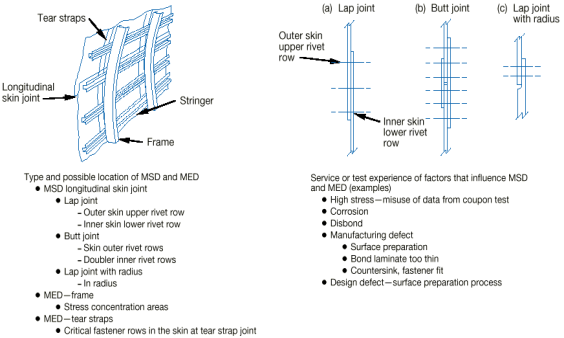
Figure A2-1: Longitudinal skin joints, frames, and tear straps (MSD/MED)

Figure A2-2: Circumferential joints and stringers (MSD/MED)
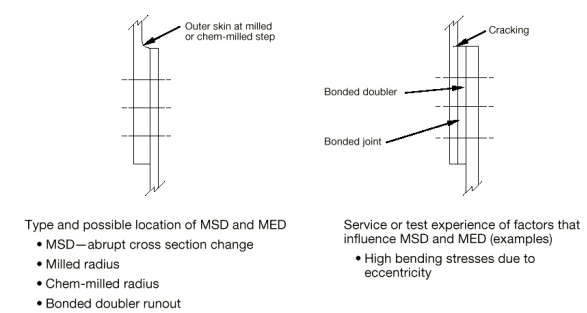
Figure A2-3: Lap joints with milled, chem-milled or bonded radius (MSD)
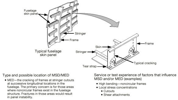
Figure A2-4: Fuselage frames (MED)
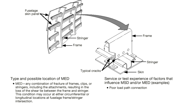
Figure A2-5: Stringer-to-frame attachments (MED)
![]()
![]()
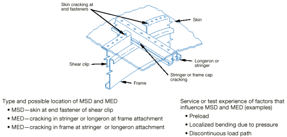
Figure A2-6: Shear clip end fasteners on shear tied fuselage frame (MSD/MED)
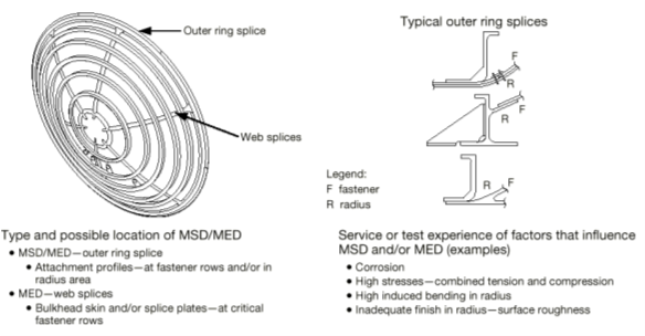
Figure A2-7: Aft pressure dome outer ring and dome web splices (MSD/MED)
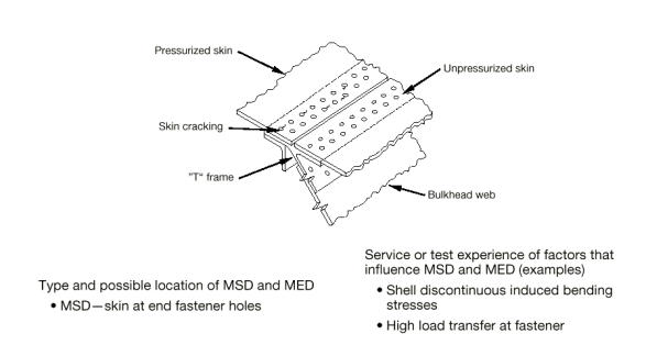
Figure A2-8: Skin splice at aft pressure bulkhead (MSD)
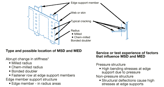
Figure A2-9: Abrupt changes in web or skin thickness — Pressurised or unpressurised structure (MSD/MED)
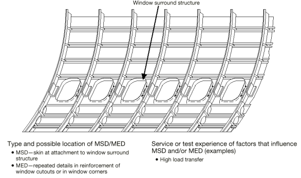
Figure A2-10: Window surround structure (MSD, MED)
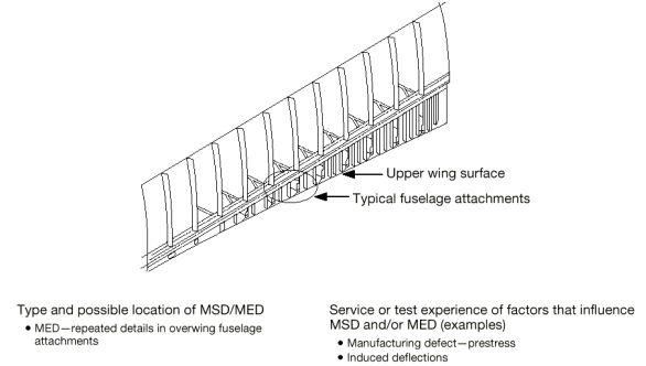
Figure A2-11: Over wing fuselage attachments (MED)
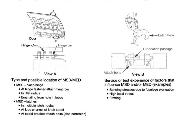
Figure A2-12: Latches and hinges of non-plug doors (MSD/MED)
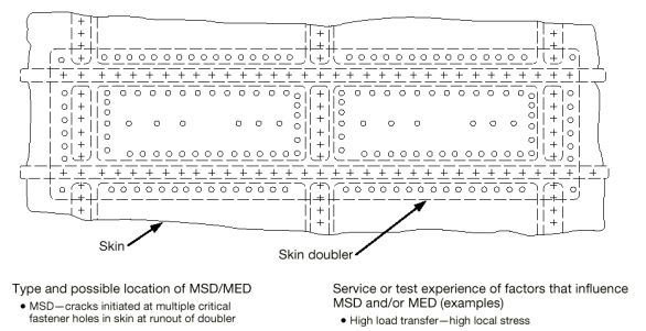
Figure A2-13: Skin at runout of large doubler (MSD) — Fuselage, wing or empennage
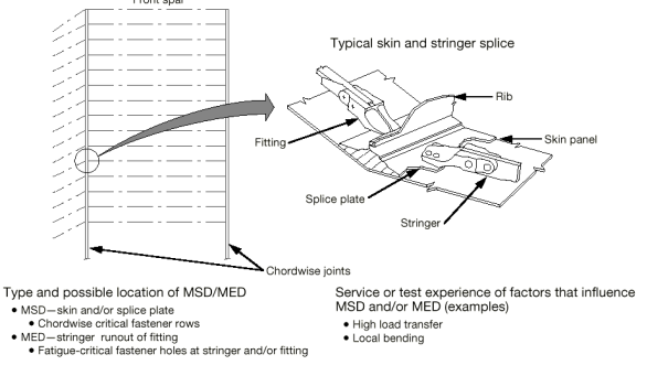
Figure A2-14: Wing or empennage chordwise splices (MSD/MED)
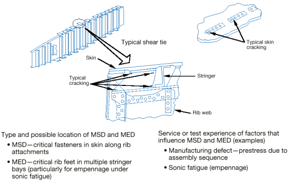
Figure A2-15: Rib-to-skin attachments (MSD/MED)
![]()
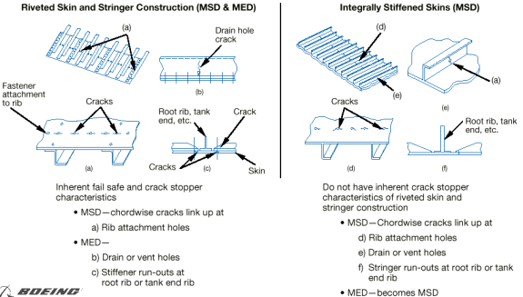
Figure A2-16: Typical wing and empennage construction (MSD/MED)
4.3 WFD Evaluation
Point 26.300 of Part-26 requires an LOV to be established according to specified timescales for large transport aeroplanes with MTOWs above 34 901 kg (75 000 lb). For other types, it is recommended that by the time the highest-time aircraft of a particular model reaches its DSG, the evaluation for each area susceptible to the development of WFD should be completed. A typical evaluation process is shown in Figure A2-19 below. This evaluation will establish the necessary elements to determine a maintenance programme to preclude WFD in that particular model’s aircraft fleet. These elements are developed for each susceptible area and include:
4.3.1 Identification of structure potentially susceptible to WFD
Unless already fully addressed in the existing fatigue and damage tolerance evaluation, the TCH should identify each part of the aircraft’s structure that is potentially susceptible to WFD for further evaluation. A justification should be given that supports selection or rejection of each area of the aircraft structure. DAHs for modified or repaired structure should evaluate their structure and its effect on existing structure.
Typical examples of structure susceptible to WFD are included in paragraph 4.2 of this Appendix.
4.3.2 Predicting when WFD will occur
(a) Characterisation of events leading to WFD
The fatigue process that leads to WFD is shown in Figure A2-17. This figure is applicable to both damage that occurs in multiple sites (MSD) and damage that occurs in similar structures at more than one location (MED). For any susceptible structural area, it is not a question of whether WFD will occur, but when it will occur. In Figure A2-17, the ‘when’ is illustrated by the line titled ‘WFD (average behaviour),’ which is the point when 50 % of the aeroplanes in a fleet would have experienced WFD in the considered area (note that the probability density function for flight cycles or flight hours to WFD has been depicted for reference). The WFD process includes this phase of crack initiation and a crack growth phase. During the crack initiation phase, which generally spans a long period of time, there is little or no change in the basic strength capability of the structure. The actual residual strength curve depicted in Figure A2-17 is flat, and equal to the strength of the structure in its pristine state. However, at some time after the first small cracks start to grow, residual strength begins to degrade. Crack growth continues until the capability of the structure degrades to the point of the minimum strength required by CS 25.571(b). In this context, the line in Figure A2-17 called WFD (average behaviour) represents a point when 50 % of the aeroplanes in a fleet fall below the minimum strength specifications of CS 25.571(b).
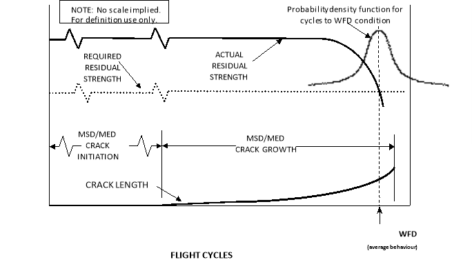
Figure A2-17: Effect on residual strength of developing WFD
(b) Determination of WFD (average behaviour) in the fleet
The time in terms of flight cycles/hours defining the WFD (average behaviour) in the fleet should be established for each susceptible structural area. The data to be assessed in determining the WFD (average behaviour) includes:
— a complete review of the service history of the susceptible areas, to identify any occurrences of fatigue cracking and the continuing validity of loads and mission profiles,
— evaluation of the operational statistics of the fleet in terms of flight hours and landings,
— significant production variants (material, design, assembly method, and any other change that might affect the fatigue performance of the detail),
— fatigue test evidence including relevant full-scale and component fatigue and damage tolerance test data (see subparagraph 4.3.9 and Annex 1 for more details),
— teardown inspections, and
— any fractographic analysis available.
The evaluation of the test results for the reliable prediction of the time to when WFD might occur in each susceptible area should include appropriate test-to-structure factors. If full-scale fatigue test evidence is used, Figure A2‑20 below relates how that data might be utilised in determining WFD (average behaviour). Evaluation may be analytically determined, supported by test and, where available, service evidence.
Regardless of whether the assessment of WFD (average behaviour) is based on in‑service data, full-scale fatigue test evidence, analyses, or a combination of any of these, the following should be considered:
4.3.3 Initial crack/damage scenario
This is an estimate of the size and extent of multiple cracking expected at MSD/MED initiation. This prediction requires empirical data or an assumption of the crack/damage locations and sequence plus a fatigue evaluation to determine the time to MSD/MED initiation. Alternatively, analysis can be based on either:
— the distribution of equivalent initial flaws, as determined from the analytical assessment of flaws found during fatigue test and/or teardown inspections regressed to zero cycles; or
— a distribution of fatigue damage determined from relevant fatigue testing and/or service experience.
4.3.4 Final cracking scenario
This is an estimate of the size and extent of multiple cracking that could cause residual strength to fall to the minimum required level as shown in A2-17. Techniques exist for 3-D elastic-plastic analysis of such problems; however, there are several alternative test and analysis approaches available that provide an equivalent level of safety. One such approach is to define the final cracking scenario as a subcritical condition (e.g. first crack at link-up). The use of a subcritical scenario reduces the complexity of the analysis and, in many cases, will not greatly reduce the total crack growth time, because the majority of the time taken to reach the critical condition is generally in the initiation phase.
4.3.5 Crack growth calculation
Progression of the crack distributions from the initial cracking scenario to the final cracking scenario should be developed. These curves can be developed:
— analytically, typically based on linear elastic fracture mechanics, or
— empirically, from test or service fractographic data.
4.3.6 Potential for discrete source damage (DSD)
A structure susceptible to fatigue including MSD/MED may also be affected by DSD due to an uncontained failure of high-energy rotating machinery (i.e. turbine engines). At this time, there is no specific requirement to address prior fatigue cracking in combination with DSD for certification. Nonetheless, when assessing in‑service findings of fatigue cracking, the additional threat posed by any potential DSD should be taken into account when developing the corrective actions and the timescales for its implementation.
4.3.7 Analysis methodology
Differences between multiple-site damage and multiple-element damage
Details of the approach used to characterise events leading up to WFD may be different. The differences will largely depend on whether MSD or MED is being considered. This is especially true for crack interaction.
(a) Crack interaction
MSD has the potential for strong crack interaction, and the effect of multiple cracks on each other needs to be addressed. MED, in most cases, does not have the same potential for strong crack interaction. The differences between the interaction effects for MSD and MED are illustrated in Figure A2-18.
(b) MSD and MED interaction
Some areas of an aeroplane are potentially susceptible to both MSD and MED. Simultaneous occurrence of MSD and MED is possible, even though it is not common. A comparison of inspection start points (ISPs) or modification start points might indicate the possibility of this occurrence. If so, the evaluation should consider the interaction between MSD and MED.
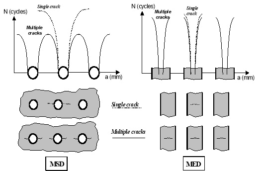
Figure A2-18: Difference between MSD and MED interaction effects
The report ‘Recommendations for Regulatory Action to Prevent Widespread Fatigue Damage in the Commercial Aeroplane Fleet’, Revision A, dated June 29, 1999 (a report of the AAWG for the ARAC’s Transport Aircraft and Engine Issues Group), discusses two Round Robin exercises developed by the TCHs to provide insight into their respective methodologies. One outcome of the exercises was an identification of key assumptions or methods that had the greatest impact on the predicted WFD behaviour. These assumptions were:
— the flaw sizes assumed at initiation of crack growth phase of analysis;
— material properties used (static, fatigue, fracture mechanics);
— ligament failure criteria;
— crack growth equations used;
— statistics used to evaluate the fatigue behaviour of the structure (e.g. time to crack initiation);
— methods of determining the structural modification point (SMP);
— detectable flaw size assumed;
— initial distribution of flaws; and
— factors used to determine bound behaviour as opposed to mean behaviour.
(c) MED
When considering MED, where interaction between cracks in different elements is not a factor, the following should be considered:
(1) In a structure containing large numbers of similar elements, there is not normally a high probability that, after a crack initiates in an element, a second crack will initiate in the element right next to it. If this does happen, however, the consequences to the overall structure may be severe. This is because having two structural members fail right next to each other can completely negate any ability of the structure to tolerate additional damage. Consequently, when performing an evaluation, applicants should make conservative assumptions and assume failures to be adjacent to each other.
(2) When an element fails completely, the load that has to be redistributed onto the non-failed structure can be large and can have a significant impact on the strength of both the cracked and uncracked structure; therefore, the effects of load redistribution must be included in the evaluation.
(d) Establishing maintenance actions
The following parameters are developed from paragraphs 4.3.2 to 4.3.7 above, and are necessary to establish an MSD/MED maintenance programme for the area under investigation.
Fatigue damage is the gradual deterioration of a material subjected to repeated loads. This gradual deterioration is a function of use and can be statistically quantified. The term ‘WFD’ is used, and can be statistically quantified, at the end of the deterioration process when the structure is no longer able to carry the residual strength loads. WFD can never be absolutely precluded because there is always some probability, no matter how small, that it will occur. Therefore, modifying or replacing structure at a predetermined, analytically-derived time stated in flight cycles or flight hours, minimises the probability of having WFD in the fleet. Modification or replacement is the most reliable method for precluding WFD. The point at which a modification is undertaken is referred to as the ‘structural modification point (SMP)’ and it is illustrated in Figure 2-1 of Annex 2. The SMP is generally a fraction of the number representing the point in time when WFD (average behaviour) will occur, and should result in the same reliability as a successful two-lifetime fatigue test. This level of reliability for setting the SMP is acceptable if MSD or MED inspections are shown to be effective in detecting cracks. If the inspections are effective, they should be implemented before the SMP. The implementation times for these inspections are known as the ‘inspection start points (ISPs)’. Repeat inspections are usually necessary to maintain this effectiveness in detecting cracks. If MSD or MED inspections are not effective in detecting cracks, then the SMP should be set at the time of ISP. For the purposes of this AMC, an inspection is effective if, when performed by properly trained maintenance personnel, it will readily detect the damage in question11 The cracking identified in the FAA Airworthiness Directive (AD) 2002-07-09 is an example of the type of cracking that MSD inspections are effective in detecting. These cracks grow from the fastener holes in the lower row of the lower skin panel in such a way that the cracking is readily detectable using NDI methods. The cracking identified in the FAA AD 2002-07-08 is an example of places where MSD inspections are not effective. These cracks grow in the outer surface and between the fastener holes in the lower row of the lower skin panel in such a way that the cracking is not readily detectable using NDI methods. Modification is the only option to address this type of cracking.. The SMP should minimise the extent of cracking in the susceptible structural area in a fleet of affected aeroplanes. In fact, if this point is appropriately determined, a high percentage of aeroplanes would not have any MSD or MED by the time the SMP is reached.
Due to the redundant nature of semi-monocoque structures, MED can be difficult to manage in a fleet environment. This stems from the fact that most aircraft structures are built-up in nature, and that makes the visual inspection of the various layers difficult. Also, visual inspections for MED typically rely on internal inspections, which may not be practical at the frequency necessary to preclude MED due to the time required to gain access to the structure. However, these issues are dependent on the specific design involved and the amount of damage being considered. In order to implement a viable inspection programme for MED, static stability must be maintained at all times and there should be no MED concurrent with MSD in a given structural area.
4.3.8 Inspection start point (ISP)
This is the point at which inspection starts if a monitoring period is used. Inspection is not practical for all applications and cannot replace the SMP. The ISP is determined through a statistical analysis of crack initiation based on fatigue testing, teardown, or service experience of similar structural details. It is assumed that the ISP is equivalent to a lower bound value with a specific probability in the statistical distribution of cracking events. Alternatively, the ISP may be established by applying appropriate factors to the average behaviour.
When inspections are determined to be effective, it is necessary to establish when those inspections should start. This point is illustrated in Figure 2-1. The start point is determined through a statistical analysis of crack initiation based on fatigue testing, teardown, or in-service experience of similar structure. The ISP is assumed to be equivalent to a lower-bound value with a specific probability in the statistical distribution of cracking events. Alternatively, an ISP may be established by applying appropriate factors to the number representing WFD (average behaviour). (e.g. for aluminium alloy structure, dividing the full-scale test result by a factor of 3).
For inspection intervals, see point 4.3.10.
4.3.9 Structural modification point (SMP)
The SMP should be established as a point in time when structures should be modified or replaced to prevent WFD from occurring. This is typically established by:
— calculating when WFD would first occur in the structure (predicted using the WFD (average behaviour)),
— setting a time before the predicted occurrence of WFD to perform modifications or replacements that will prevent it.
The applicant should demonstrate that the proposed SMP established during the evaluation has the same confidence level as current regulations require for new certification. In lieu of other acceptable methods, the SMP for aluminium alloy structures can be established as a point reduced from the WFD (average behaviour), based on the viability of inspections in the monitoring period. The SMP may be determined by dividing the number representing the timing when WFD (average behaviour) will occur by a factor of 2 if there are effective inspections, or by a factor of 3 if inspections are not effective. For other materials such as high‑strength steel alloys, larger scatter factors may be necessary to account for increased variability in fatigue performance.
An aircraft should not be operated past the SMP unless the structure is modified or replaced, or unless additional approved data is provided that would extend the SMP. However, if during the structural evaluation for WFD, a TCH/DAH finds that the flight cycles and/or flight hours SMP for a particular structural detail have been exceeded by one or more aircraft in the fleet, the TCH/DAH should expeditiously evaluate selected high-time aircraft in the fleet to determine their structural condition. From this evaluation, the TCH/DAH should notify the competent authorities and propose appropriate service actions.
A DAH may find that the SMP for a particular structural area has been exceeded by one or more aeroplanes in the fleet. In that case, the DAH should expedite the evaluation of those high-time aeroplanes to determine their structural condition, notify EASA and propose appropriate maintenance actions specific to those aeroplanes.
The initial SMP may be adjusted based on the following:
(a) The tasks necessary to extend an SMP may include any or all of the following:
(1) Additional fatigue or residual strength tests, or both, on a full-scale aeroplane structure or a full-scale component followed by detailed inspections and analyses.
(2) Fatigue tests of new structure or structure from in-service aeroplanes on a smaller scale than full component tests (i.e. subcomponent or panel tests, or both). If a subcomponent test is used, the SMP would be extended only for that subcomponent.
(3) Teardown inspections (destructive) on structural components that have been removed from service.
(4) Teardown inspections (non-destructive) accomplished by selected, limited disassembly and subsequent reassembly of specific areas of high-time aeroplanes.
(5) Analysis of in-service data (e.g. inspections) from a statistically significant number of aeroplanes.
(b) If cracks are found in the structural detail for which the evaluation was done during either the monitoring period or the modification programme, the SMP should be re-evaluated to ensure that the SMP does in fact provide the required confidence level. If it is shown that the required confidence level is not being met, the SMP should be adjusted and the adjustment reflected in the appropriate SBs to address the condition of the fleet. Additional regulatory action may be required.
4.3.10 Inspection interval and method
An interval should be chosen to provide a sufficient number of inspections between the ISP and the SMP so that there is high confidence that no MSD/MED condition will reach the final cracking scenario without detection. The interval between inspections depends on the detectable crack size, the critical crack lengths and the probability that the cracks will be detected with the specific inspection method. Conservative scenarios should be assumed for developing the inspection interval unless other assumptions can be consistently supported by test and service experience. If the crack cannot be detected, the SMP must be re-evaluated to ensure there is a high confidence level that no aircraft will develop MSD/MED before modification.
4.4 Evaluation of maintenance actions
For all areas that have been identified as susceptible to MSD/MED, the current maintenance programme should be evaluated to determine whether adequate structural maintenance and inspection programmes exist to safeguard the structure against unanticipated cracking or other structural degradation. The evaluation of the current maintenance programme typically begins with the determination of the SMP for each area.
Each area should then be reviewed to determine the current maintenance actions and compare them to the maintenance needs established in this evaluation. Issues to be considered include the following:
(a) Determine the inspection requirements (method, inspection start point, and repeat interval) of the inspection for each susceptible area (including that structure that is expected to arrest cracks) that is necessary to maintain the required level of safety.
(b) Review the elements of the existing maintenance programmes already in place.
(c) Revise and highlight elements of the maintenance programme necessary to maintain safety.
For susceptible areas approaching the SMP, where the SMP will not be increased or for areas that cannot be reliably inspected, a programme should be developed and documented that provides for replacement or modification of the susceptible structural area.
4.4.1 Period of WFD evaluation validity
At whatever point the WFD evaluation is made, it should support the LOV of the maintenance programme. Consistent with the use of test evidence to support individual SMPs, as described above in paragraph 4.3.9, the LOV of the maintenance programme should be based on fatigue test evidence. For an existing ageing aircraft type, the initial WFD evaluation of the complete airframe will typically cover a significant forward estimation of the projected aircraft usage beyond its DSG, also known as the ‘proposed ESG’ and is effectively a proposed LOV. Typically, an evaluation through an additional 25 % of the DSG would provide a realistic forecast, with reasonable planning time for necessary maintenance action. However, it may be appropriate to adjust the evaluation validity period depending on issues such as:
(a) the projected useful life of the aircraft at the time of the initial evaluation;
(b) current NDI technology; and
(c) airline advance planning requirements for introduction of new maintenance and modification programmes, to provide sufficient forward projection to identify all likely maintenance/modification actions essentially as one package.
Upon completion of the evaluation and publication of the revised maintenance requirements, the ‘proposed ESG’ becomes the LOV.
Note: This assumes that all other aspects of the maintenance programme that are required to support the LOV (such as SSID, CPCP, etc.) are in place and have been evaluated to ensure they too remain valid up to the LOV.
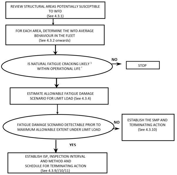
NOTES:
1. Fatigue cracking is defined as likely if the factored fatigue life is less than the projected ESG of the aircraft at time of WFD evaluation.
2. The operational life is the projected ESG of the aircraft at time of WFD Evaluation. (See 4.4.1).
Figure A2-19: Aircraft WDF evaluation process
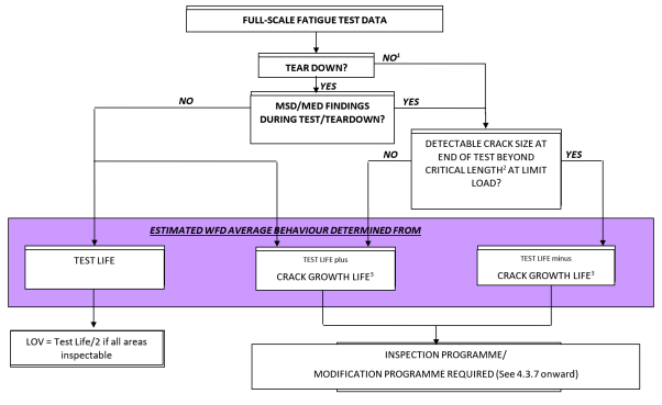
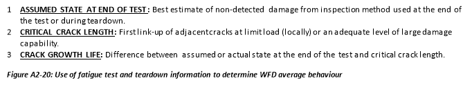
5. DOCUMENTATION
Any person seeking approval of an LOV of an aircraft type design should develop a document containing all the necessary ISPs, inspection procedures, replacement times, SMPs, and any other maintenance actions necessary to preclude WFD, and to support the LOV. That person must revise the SSID or ALS as necessary, and/or prepare SBs that contain the aforementioned maintenance actions. Since WFD is a safety concern for all operators of older aircraft, EASA will make mandatory the identified inspection and modification programmes. In addition, EASA may consider separate AD action to address any SBs or other service information publications revised or issued as a result of in-service MSD/MED findings resulting from implementation of these programmes.
The following items should be contained in the front of the documentation supporting the LOV:
(a) identification of the variants of the basic aircraft type to which the document relates;
(b) summary of the operational statistics of the fleet in terms of hours and flights;
(c) description of the typical mission, or missions;
(d) the types of operations for which the inspection programme is considered valid;
(e) reference to documents giving any existing inspections, or modification of parts or components; and
(f) the LOV of the maintenance programme in terms of flight cycles or flight hours or both as appropriate to accommodate variations in usage.
The document should contain at least the following information for each critical part or component:
(a) description of the primary structure susceptible to WFD;
(b) details of the monitoring period (ISP, repeat inspection interval, SMP, inspection method and procedure (including crack size, location and direction) and alternatives) when applicable;
(c) any optional modification or replacement of the structural element as terminating action to inspection;
(d) any mandatory modification or replacement of the structural element;
(e) SBs (or other service information publications) revised or issued as a result of in-service findings resulting from the WFD evaluations (added as a revision to the initial WFD document); and
(f) guidance to the operator on which inspection findings should be reported to the TCH/DAH, and appropriate reporting forms and methods of submission.
6. REPORTING REQUIREMENTS
Operators, TCHs and STCHs are required to report in accordance with various regulations (e.g. point 21.A.3A, and point 145.A.60). The regulations to which this AMC relates do not require any reporting requirements in addition to the current ones. Due to the potential threat to structural integrity, the results of inspections must be accurately documented and reported in a timely manner to preclude the occurrence of WFD. The current system of operator and TCH communication has been useful in identifying and resolving a number of issues that can be classified as WFD concerns. MSD/MED has been discovered via fatigue testing and in-service experience. TCHs have been consistent in disseminating related data to operators to solicit additional service experience. However, a more thorough means of surveillance and reporting is essential to preclude WFD.
When damage is found while conducting an approved MSD/MED inspection programme, or at the SMP where replacement or modification of the structure is occurring, the TCHs, STCHs and the operators need to ensure that greater emphasis is placed on accurately reporting the following items:
(a) a description (with a sketch) of the damage, including crack length, orientation, location, flight cycles/hours, and condition of structure;
(b) results of follow-up inspections by operators that identify similar problems on other aircraft in the fleet;
(c) findings where inspections accomplished during the repair or replacement/modification identify additional similar damage sites; and
(d) adjacent repairs.
Operators must report all cases of MSD/MED to the TCH, STCH or the competent authority as appropriate, irrespective of how frequently such cases occur. Cracked areas from in-service aircraft (damaged structure) may be needed for detailed examination. Operators are encouraged to provide fractographic specimens whenever possible. Aeroplanes undergoing heavy maintenance checks are perhaps the most useful sources for such specimens.
Operators should remain diligent in the reporting of potential MSD/MED concerns not identified by the TCH/DAH. Indications of a developing MSD/MED problem may include:
(a) damage at multiple locations in similar adjacent details;
(b) repetitive part replacement; or
(c) adjacent repairs.
Documentation will be provided by the TCH and STCH as appropriate to specify the required reporting format and time frame, supporting the mandatory reporting regulations (e.g. point 21.A.3A of Part 21, point 145.A.60 of Part-145). The data will be reviewed by the TCH or STCH, operator(s), and EASA to evaluate the nature and magnitude of the problem and to determine the appropriate corrective action.
7. WFD EVALUATION FOR STRUCTURAL MODIFICATIONS AND REPAIRS
TCHs of aeroplanes subject to the point 26.303 of Part-26 requirements for an LOV should perform WFD evaluations to assess all the applicable existing structure and the effect of future changes on the LOV.
The WFD evaluations of this AMC do not apply retroactively to existing STCH’s modifications, nor to existing repairs. Future changes and repairs need to take into account the applicable certification basis, and applicants should consider the guidance of the applicable ACJ and AMC as discussed in paragraph 8 of this AMC. The DTEs for compliance with points 26.307, 26.308, 26.333 and 26.334 of Part-26 do not have to consider WFD (average behaviour), or the related SMP and ISP.
In cases where a new DTE is performed by DAHs to comply with points 26.333 and 26.334 of Part-26 for existing changes or for new changes or repairs, according to CS 25.571 Amdt 18 or earlier amendments, the DTE and development of DTIs should take into account the cracking scenarios that could reasonably be expected to occur in the remaining operational lifetime of an aeroplane into which the repair or modification is, or may be, incorporated.
8. RESPONSIBILITY FOR WFD EVALUATION, ESTABLISHING THE LOV AND IMPLEMENTATION OF THE LOV AND MAINTENANCE ACTIONS
The primary responsibility is with the DAH to perform the analyses and supporting tests. However, it is expected that if extensive maintenance actions are necessary, the practicality of their implementation will be evaluated in a cooperative effort between the operators and TCHs/DAHs, with participation of EASA.
The TCH is responsible for proposing and submitting an LOV in the ALS for approval.
Note: In some cases, the ALS may already contain an LOV which is approved in accordance with a regulation of another authority. There may also be other potentially more restrictive limitations on the validity of maintenance programmes. For these cases, when the TCH needs to publish the LOV as required by point 26.303 of Part-26, this LOV and its relationship with the existing or superseded limitation should be clearly described so that no operator will exceed the most restrictive applicable limit on the general validity of the maintenance programme.
The operator is responsible for implementing the LOV in their maintenance programme.
Note: The LOV does not supersede or allow operations beyond any lower limitation applicable to the individual aeroplane and the components controlled by the maintenance programme.
[Amdt 20/2]
[Amdt 20/20]
Annex 1 to Appendix 2 to AMC 20-20A Full-scale fatigue test evidence
ED Decision 2020/023/R
Contents
(a) Overview
(b) Full-scale fatigue test evidence
(c) Key elements of a full-scale fatigue test programme
(1) Article
(2) Test set-up and loading
(i) Test set-up
(ii) Test loading
(3) Test duration
(i) New type certificates and derivatives
(ii) Repairs and type design changes
(4) Post-test evaluation
(i) Residual strength tests
(ii) Teardown inspections
(d) Scope of full-scale fatigue test article
(1) New type designs
(2) Derivative models
(3) Type design changes — SBs
(4) Type design changes — STCs
(5) Major repairs
(e) Use of existing full-scale fatigue test data
(f) Use of in-service data
(a) Overview
CS 25.571(b) Amendment 19 specifies that special consideration for WFD must be included in the fatigue and damage tolerance evaluation where the design is such that this type of damage could occur. CS 25.571(b) Amendment 19 specifies the effectiveness of the provisions to preclude the possibility of WFD occurring within the limits of validity of the maintenance programme to be demonstrated with sufficient full-scale fatigue test evidence. The determination of what constitutes ‘sufficient full-scale test evidence’ requires a considerable amount of engineering judgement and is a matter that should be discussed and agreed to between an applicant and EASA early in the planning stage of a certification project. Sufficient test evidence is also necessary to support compliance with CS 26.303 and the most straightforward means of compliance is to utilise existing full-scale test evidence.
(b) Full-scale fatigue test evidence
In general, sufficient full-scale fatigue test evidence consists of full-scale fatigue testing to at least twice the LOV, followed by specific inspections and analyses to determine that WFD has not occurred. The following factors should be considered in determining the sufficiency of the evidence:
Factor 1: The comparability of the load spectrum between the test and the projected usage of the aeroplane.
Factor 2: The comparability of the airframe materials, design and build standards between the test article and the certified aeroplane.
Factor 3: The extent of post-test teardown inspection, residual strength testing and analysis for determining whether widespread fatigue cracking has occurred.
Factor 4: The duration of the fatigue testing.
Factor 5: The size and complexity of a design or build standard change. This factor applies to design changes made to a model that has already been certified and for which full-scale fatigue test evidence for the original structure should have already been determined to be sufficient. Small, simple design changes, comparable to the original structure, could be analytically determined to be equivalent to the original structure in their propensity for WFD. In such cases, additional full-scale fatigue test evidence should not be necessary.
Factor 6: In the case of major changes and STCs, the age of an aeroplane being modified. This factor applies to aeroplanes that have already accumulated a portion of their LOV prior to being modified. An applicant should demonstrate freedom from WFD up to the LOV in place for the original aeroplane and may take into account the age of the aeroplane being modified.
(c) Key elements of a full-scale fatigue test programme
The following guidance addresses key elements of a test programme that is intended to generate the data necessary to support compliance, and it can also be used to evaluate and interpret existing full-scale test data for the purposes of supporting compliance with point 26.303 of Part-26.
(1) Article. The test article should be representative of the structure of the aeroplane to be evaluated (i.e. ideally a production-standard article). The attributes of the type design that could affect MSD/MED initiation, growth and subsequent residual strength capability should be replicated as closely as possible on the test article. Critical attributes include, but are not limited to, the following:
— material types and forms;
— dimensions;
— joining methods and details;
— coating and plating;
— the use of faying surface sealant;
— assembly processes and sequences; and
— the influence of secondary structure (e.g. loads induced due to proximity to the structure under evaluation).
(2) Test set-up and loading. The test set-up and loading should result in a realistic simulation of the expected operational loads.
(i) Test set-up. The test set-up dictates how loads are introduced into the structure and reacted. Every effort should be made to introduce and react loads as realistically as possible. When a compromise is made (e.g. wing air loading), the resulting internal loads should be evaluated (e.g. using finite element methods) to ensure that the structure is not being unrealistically underloaded or overloaded, locally or globally.
(ii) Loading spectrum. The test loading spectrum should include loads from all damaging sources (e.g. cabin pressurisation, manoeuvres, gusts, engine thrust, control surface deflections, and landing impacts) that are significant for the structure being evaluated. Consideration should also be given to temperature and other environmental effects that may affect internal loads. A supporting rationale should be provided when a load source is not represented in a sequence. Additionally, differences between the test sequence and the expected operational sequence should be justified. For example, it is standard practice to eliminate low loads that are considered to be non-damaging and to clip high infrequent loads that may non-conservatively bias the outcome, but care should be taken in both cases so that the test results are representative.
(3) Test duration. For any WFD-susceptible area, the average time in flight cycles and/or hours to develop WFD should first be determined. This is referred to as the WFD (average behaviour) for the subject area. The area should be modified or replaced at one third of this time unless inspection for MSD/MED is practical. If inspection is practical, that inspection should start at one third of the WFD (average behaviour), with modification/replacement at one half of that time. It is standard practice to interpret the non-factored fatigue life of one specimen as the average life. It follows that if one full‑scale fatigue test article survives a test duration of X time without an occurrence of WFD, it can be conservatively assumed that the WFD (average behaviour) of all susceptible areas is equal to X. Based on this, and assuming that the susceptible areas are impractical to inspect for MSD/MED, the replacement or modification should be implemented at X/3. For areas where MSD/MED inspections are practical, replacement/modification could be deferred until X/2, but MSD/MED inspections would have to start at X/3. The procedure should be kept in mind when deciding what the test duration will be.
(4) Post-test evaluation. One of the primary objectives of the full-scale fatigue test is to generate the data needed to determine the absolute WFD (average behaviour) for each susceptible area, or to establish a lower bound. Recall that the definition of WFD (average behaviour) is the average time required for MSD/MED to initiate and grow to the point that the static strength capability of the structure is reduced to less than the residual strength requirements of CS 25.571(b). Some work is required at the end of the test to determine the strength capability of the structure, either directly or indirectly.
(i) Residual strength tests. One acceptable way to demonstrate freedom from WFD at the end of a full-scale fatigue test is to subject the article to the required residual strength loads specified in CS 25.571(b). If the test article sustains the loads, it can be concluded that the point of WFD has yet to be reached for any of the susceptible areas. However, because fatigue cracks that might exist at the end of the test are not quantified, it is not possible to determine how far beyond the test duration WFD would occur in any of the susceptible areas without accomplishing additional work (e.g. teardown inspection). Additionally, metallic test articles may be non‑conservatively compromised relative to their future fatigue performance if static loads in excess of representative operational loads are applied. Residual strength testing could preclude the possibility of using an article for additional fatigue testing.
(ii) Teardown inspections. The residual strength capability may be evaluated indirectly by performing teardown inspections to quantify the size of any MSD/MED cracks that might be present, or to establish a lower bound on crack size based on the capability of the inspection method. Once this is done, the residual strength capability can be estimated analytically. Depending on the results, crack growth analyses may also be required to project backwards or forwards in time to estimate the WFD (average behaviour) for an area. As a minimum, teardown inspection methods should be capable of detecting the minimum size of MSD or MED cracking that would result in a WFD condition (i.e. residual strength degraded to less than the level specified in CS 25.571(b)). Ideally, it is recommended that inspection methods should be used that are capable of detecting MSD/MED cracking before it degrades the strength to less than the required level. Effective teardown inspections that are required to demonstrate freedom from WFD typically require significant resources. They typically require disassembly (e.g. fastener removal) and destruction of the test article. All areas that are or may be susceptible to WFD should be identified and examined.
(d) Scope of full-scale fatigue test article
The following examples offer some guidance on the types of data sets that might constitute ‘sufficient evidence’ for some kinds of certification projects. The scope of the test specimen and the duration of the test are considered.
(1) New type designs
Normally, this type of project would necessitate its own full-scale fatigue test of the complete airframe to represent the new structure and its loading environment. Nevertheless, prior full-scale fatigue test evidence from earlier tests performed by the applicant, or others, may also be used, and could supplement additional tests on the new model. Ultimately, the evidence needs to be sufficient to conclude with confidence that, within the LOV of the airframe, WFD will not occur. Factors 1 to 4 should be considered in determining the sufficiency of the evidence.
A test duration of a minimum of twice the LOV for the aeroplane model would normally be necessary if the loading spectrum is realistic, the design and construction for the test article principal structure are the same as for the certified aeroplane, and the post-test teardown is exhaustive. If conformance to Factors 1 through 3 is less than ideal, a significantly longer test duration would be needed to conclude with confidence that WFD will not occur within the LOV. Moreover, no amount of fatigue testing will suffice if conformance to Factors 1 through 3 above is not reasonable. Consideration should also be given to the possible future need for life extension or product development, such as potential weight increases, etc.
(2) Derivative models
The default position would be to test the entire airframe. However, it may be possible to reliably determine the occurrence of WFD for all or part of the derivative model from the data that the applicant generated or assembled during the original certification project. Nevertheless, the evidence needs to be sufficient to allow confidence in the calculations which show that WFD will not occur within the LOV of the aeroplane. Factors 1 through 5 should be considered in determining the sufficiency of the evidence for derivative models. For example, a change in the structural design concept, a change in the aerodynamic contours, or a modification of a structure that has a complex internal load distribution might well make analytical extrapolation from the existing full-scale fatigue test evidence very uncertain. Such changes might well necessitate full-scale fatigue testing of the actual derivative principal structure. On the other hand, a typical derivative often involves extending the fuselage by inserting ‘fuselage plugs’ that consist of a copy of the typical semi-monocoque construction for that model, with slightly modified material gauges. Normally this type of project would not necessitate its own full-scale fatigue test, particularly if very similar load paths and operating stress levels are retained.
(3) Type design changes — SBs
Normally, this type of project would not necessitate its own full-scale fatigue test because the applicant would have generated, or assembled, sufficient full-scale fatigue test evidence during the original certification project that could be applied to the change. Nevertheless, as cited in the previous example, the evidence needs to be sufficient to allow confidence in the calculations which show that WFD will not occur within the LOV of the aeroplane. In addition, Factor 5, ‘The size and complexity of a design change’, should be considered.
(4) Type design changes — STCs
(i) Sufficient full-scale test evidence for structures certified under an STC may necessitate additional full-scale fatigue testing, although the extent of the design change may be small enough to use Factor 5 to establish the sufficiency of the existing full-scale fatigue test evidence. The applicant for an STC may not have access to the original equipment manufacturer (OEM)’s full-scale fatigue test data. For aeroplane types for which an LOV has been published, the STC applicant may assume that the basic structure was free from WFD up to the LOV, unless EASA has taken AD action, or intends to take action (by a proposed AD) to alleviate a WFD condition, or inspections or modifications exist in the ALS relating to WFD conditions. For the purpose of the STC applicant’s demonstration that WFD will not occur on its modification (or the underlying original structure) within the LOV, it may be assumed that the model types, to which the LOV is applicable, have received at least two full LOVs of fatigue testing, under realistic loads, and have received thorough post-test inspections that did not detect any WFD, or the ALS includes from the outset details of the modifications required to address WFD that will need specific consideration by the STC applicant. With this knowledge, and Factors 1 through 5, the STC applicant may be able to demonstrate that WFD will not occur on its modification (or the underlying original structure) within the LOV. If, however, the modification significantly affects the distribution of stress in the underlying structure, or significantly alters loads in other parts of the aeroplane, or significantly alters the intended mission of the aeroplane, or if the modification is significantly different in its structural concept from the certified aeroplane being modified, additional representative fatigue test evidence would be necessary.
(ii) In addition, Factor 6 ‘The age of the aeroplane being modified’ comes into play for modifications made to older aeroplanes. The STC applicant should demonstrate freedom from WFD up to the LOV of the aeroplane being modified. For example, an applicant for an STC to an aeroplane that has reached an age equivalent to 75 % of its LOV should demonstrate that the modified aeroplane will be free from WFD for at least the remaining 25 % of the LOV. Although an applicant could attempt to demonstrate freedom from WFD for a longer period, this may not be possible unless the OEM cooperates by providing data for the basic structure. A short DSG for the modification could simplify the demonstration of freedom from WFD for the STC applicant. Nevertheless, the applicant should also be aware that the LOV of the aeroplane is not a fixed life; it may be extended as a result of a structural re‑evaluation and service action plan, such as those developed for certain models under the FAA’s ‘Aging Aircraft Program’. Unless the modifier also re-evaluates its STC modification, the shorter goal for the modification could impede extending the LOV of the modified aeroplanes.
(5) Major repairs. New repairs (for which the applicable certification basis requires WFD evaluation) that differ from the repairs contained in the OEM’s SRM, but that are equivalent in design from such repairs, and that meet CS-25 specifications in other respects, would not necessitate full-scale fatigue testing to support freedom from WFD up to the LOV. Major repair solutions (that may be susceptible to WFD) which utilise design concepts (e.g. new materials, other production processes, new design details) different from the previously approved repair data may need further testing.
(e) Use of existing full-scale fatigue test data
In some cases, especially for establishing an LOV in accordance with point 26.303 of Part-26, or for derivative models and type design changes accomplished by the TCH, there may be existing full-scale fatigue test data that may be used to support compliance and mitigate the need to perform additional testing.
Any physical differences between the structure originally tested and the structure being considered that could affect its fatigue behaviour must be identified and reconciled. Differences that should be addressed include, but are not limited to, differences in any of the physical attributes listed under point (c)(1) of this Annex and differences in operational loading. Typical developments that affect the applicability of the original LOV demonstration data are the:
— gross weight (e.g. if it increases),
— cabin pressurisation (e.g. a change in the maximum cabin or operating altitude), or
— flight segment parameters.
The older the test data, the harder it may be to demonstrate that it is sufficient. Often test articles were not conformed, neither were test plans or reports submitted to EASA as part of the compliance data package. The rigour of loading sequences has varied significantly over the years, and from OEM to OEM. Additionally, testing philosophies and protocols were not standardised. For example, post-test evaluations, if any, varied significantly and in some cases consisted of nothing more than limited visual inspections. However, there may be acceptable data from the early full-scale fatigue tests that the applicant proposes to use to support compliance. In order to use such data, the configuration of the test article and the loading must be verified, and the issue of the residual strength capability of the article (or teardown data) at the end of the test must be addressed.
(f) Use of in-service data
There may be in-service data that can be used to support WFD evaluations. Examples of such data are as follows:
— Documented positive findings of MSD/MED cracks that include the location, size and the time in service of the affected aeroplane, along with a credible record of how the aircraft had been operated since the original delivery.
— Documented negative findings from in-service inspections for MSD/MED cracks on a statistically significant number of aeroplanes, with the time in service of each aircraft, and a credible record of how each aircraft had been operated since the original delivery. For this data to be useful, the inspection methods used should have been capable of detecting MSD/MED crack sizes equal to or smaller than those sizes that could reduce the strength of the structure to less than the residual strength levels specified in CS 25.571(b).
— Documented findings from the destructive teardown inspection of structures from in‑service aircraft. This might be structures (e.g. fuselage splices) removed from the aircraft that were subsequently returned to service, or from retired aircraft. It would also be necessary to have a credible record of the operational loading experienced by the subject structure up to the time it was taken out of service.
Prior to using in-service data, any physical or loading differences that exist between the structure of the in-service or retired aeroplanes and the structure being certified should be identified and reconciled as discussed above.
[Amdt 20/20]
Annex 2 to Appendix 2 to AMC 20-20A Example of how to establish an LOV
ED Decision 2020/023/R
This Annex provides a simplified example of how to establish an LOV for a specified aeroplane structural configuration. The process for establishing an LOV involves four steps:
Step 1. Identifying a candidate LOV for the aeroplane structural configuration.
Step 2. Identifying WFD-susceptible structure. For this evaluation, it was determined that the aeroplane structural configuration had six areas with WFD-susceptible structures.
Step 3. Performing a WFD evaluation for each of the six areas of WFD-susceptible structure to determine whether there are inspection start points and structural modification points for the candidate LOV identified. This allows the evaluation of the candidate LOV.
Figure 2-1, shown below, shows the WFD behaviour for one WFD-susceptible area. The figure also shows three different candidate LOVs. Candidate LOV1 is at a point that occurs significantly before the WFD average behaviour line. This LOV will not require any maintenance actions. Candidate LOV2 occurs before the WFD average behaviour line, but closer to it. As a result, inspection will need to start before the LOV. Although candidate LOV3 occurs before the WFD average behaviour line, with this LOV, the probability of WFD in the fleet is unacceptable, and inspection and subsequent modification or replacement is required before the aeroplane reaches LOV3. Note that for LOV2 and LOV3, if inspections were determined to be unreliable, then the SMP would occur at the point on the chart where the ISP is. Using this example, this decision-making process needs to be repeated for all six WFD-susceptible areas.
Applicants should evaluate the candidate LOVs and the results of WFD evaluations for each susceptible area.
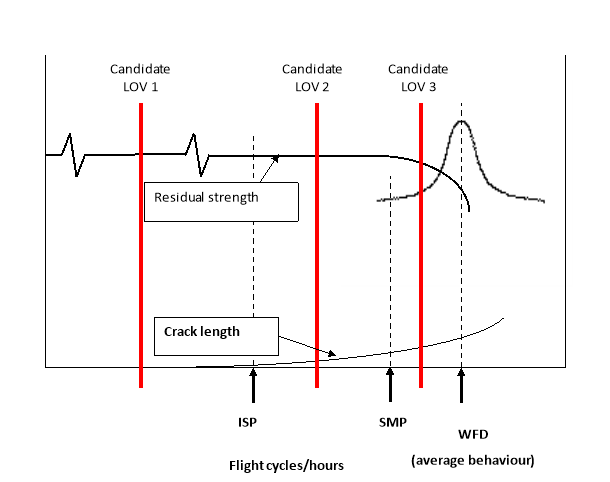
Figure 2-1: Comparison of WFD-susceptible structure to aircraft LOV
Step 4. Finalising the LOV. Once all the susceptible areas have been evaluated, the final step is to determine where to establish the LOV that will be proposed for compliance. Figure 2-2 shows the results of the WFD evaluation of the six WFD-susceptible areas. As it is shown, there are inspections and modifications or replacements that should be performed over time to preclude WFD. Any LOV can be valid as long as it is demonstrated that, based on its inherent fatigue characteristics and any required maintenance actions, the aeroplane model will be free from WFD up to the LOV. The example in Figure 2-2 includes three LOVs that could be proposed for compliance.
— LOV1: Maintenance actions are not required to address WFD.
— LOV2: Inspection and modification or replacement of area four are required to address WFD.
— LOV3: The DAH may propose an LOV that is greater than LOV2. However, as shown in Figure 2‑2, that would result in more maintenance actions than identified for LOV2. Operators would be required to perform maintenance actions in four out of the six WFD-susceptible areas. Areas 1, 2 and 4 would have to be inspected prior to the LOV. Areas 3 and 5 are free from WFD maintenance actions. Area 4 would be required to be inspected and modified, and then the modification would be required to be inspected prior to the LOV. Area 6 would require modification prior to reaching the LOV. Some of the maintenance actions required for the LOV may have already been issued in an SB and mandated by an AD. For the rest, ADs will need to be issued.

Figure 2-2: Aeroplane maintenance actions
[Amdt 20/20]
Appendix 3 to AMC 20-20A Guidelines for establishing instructions for continued airworthiness of structural repairs and modifications
ED Decision 2020/023/R
With an SSID, CPCP, mandatory modifications and an LOV in place, an individual aircraft may still not meet the intended level of airworthiness for ageing aircraft structures. Repairs and modifications to aircraft structure also warrant investigation. It is recommended that for large transport aeroplanes, all repairs and modifications that affect the FCS should be assessed using some form of damage-tolerance-based evaluation. A regulatory requirement for damage tolerance was not applied to aeroplane design types certified before 1978, and even after this time, the implementation of DTE on repairs and modifications was not consistent. Therefore, the damage tolerance characteristics of repairs and modifications may vary widely and are largely unknown. In view of these concerns, it is necessary to perform an assessment of the repairs and modifications on certain aircraft in service to establish their damage tolerance characteristics. Further information on the background to the need for damage‑tolerance‑based inspection programmes for repairs is provided in Annex 6 to this Appendix.
Repairs and modifications to aeroplanes certified to JAR 25 Change 7 or 14 CFR 25 Amendment 45 or later must comply with the fatigue and damage tolerance requirements of their certification basis. In addition, points 26.307, 26.308, 26.309, 26.332 to 26.334 and 26.370 of Part-26 define additional requirements for certain repairs and modifications that must be addressed using the damage tolerance methodology.
In cases where a new DTE is performed by DAHs to comply with points 26.333 and 26.334 of Part-26 for existing changes or for new changes or repairs, according to CS 25.571 Amendment 18 or earlier amendments, the DTE and development of DTI should take into account the cracking scenarios that could reasonably be expected to occur in the remaining operational lifetime of the aeroplane into which the repair or modification can be incorporated.
2. DEFINITIONS
See paragraph 4 of this AMC.
3. ESTABLISHMENT OF A DAMAGE-TOLERANCE-BASED INSPECTION PROGRAMME FOR REPAIRS AFFECTING FCS
3.1 Overview of the TCH tasks for repairs that may affect the FCBS
(a) Identify the affected aircraft model, models, aircraft serial numbers, and DSG stated as a number of flight cycles, flight hours, or both.
(b) Identify the certification level.
(c) Identify and develop a list of FCBS.
(d) Submit the list of FCBS to EASA for approval, and make it available to operators and STCHs.
(e) Review and update published repair data as necessary.
(f) Submit any new or updated published repair data to EASA for approval (or approve the data in accordance with Subpart M of Part 21), and make it available to operators.
(g) Develop REGs and submit them to EASA for approval, and make the approved REGs available to operators.
3.2. Certification level
In order to understand what data is required, the TCH should identify the amendment level of the original aircraft certification relative to CS 25.571. The amendment level is useful in identifying what DT data may be available and what standard should be used for developing new DT data. The two relevant aircraft groups are:
Group A Aircraft certified to CAR 4b or 14 CFR § 25.571, prior to Amendment 25-45 or JAR 25 Change 7 or equivalent. These aircraft were not evaluated for damage tolerance as part of the original type certification. Unless previously accomplished, existing and future repairs to FCBS will need DT data to be developed.
Group B Aircraft certified to JAR 25 Change 7 or 14 CFR § 25.571, Amendment 25-45 or later. These aircraft were evaluated for damage tolerance as part of the original type certification. As noted in the introduction, some of these repairs may not have repair data that includes appropriate DTI and the TCH and operators may need to identify and perform a DTE of these repairs and develop DTIs.
3.3. Identifying fatigue-critical baseline structure (FCBS)
TC holders should identify and make available to operators a list of baseline structure that is susceptible to fatigue cracking that could contribute to a catastrophic failure. The term ‘baseline’ refers to the structure that is designed under the original type certificate or amended type certificate for that aircraft model (that is, the ‘as delivered aircraft model configuration’). Guidance for identifying this structure can be found in CS-25 AMC 25.571. This structure is referred to in this AMC as ‘fatigue-critical baseline structure.’ The purpose of requiring identification and listing of FCS is to provide operators with a tool that will help in evaluating existing and future repairs or modifications. In this context, FCS is any structure that is susceptible to fatigue that could contribute to a catastrophic failure, and should be subject to a DTE. The DTE would determine if DTIs need to be established for the repaired or modified structure. For the purpose of this AMC, structure that is modified after aircraft delivery from the TCH is not considered to be ‘baseline’ structure.
CS 25.571(a) states ‘An evaluation of the strength, detail design, and fabrication must show that catastrophic failure due to fatigue environmental and accidental damage, will be avoided throughout the operational life of the aeroplane. This evaluation must be conducted … for each part of the structure which could contribute to a catastrophic failure (such as wing, empennage, control surfaces, fuselage, engine mounts, and their related primary attachments) …’. When identifying FCBS, it is not sufficient to consider only that structure identified in the SSID or ALS. Some SSIDs or ALSs might only include supplemental inspections of the most highly stressed elements of the FCBS. An SSID or ALS often refers to this structure as a PSE. If repaired, other areas of structure not identified as a PSE in the SSID or ALS may require supplemental inspections. The term PSE has, at times, been interpreted narrowly by industry. The narrow application of the term PSE could incorrectly limit the scope of the structure that would be considered relative to fatigue if repairs or modifications exist or are made subsequently. The relationship between PSE and FCS could vary significantly depending on the TCH’s working definition of PSE. In addition, there may be structure whose failure would be catastrophic, but due to low operational loads on the part, the part will not experience fatigue cracking. However, if the subject part is repaired or modified, the stresses in the part may be increased to a level where it is now susceptible to fatigue cracking. These types of parts should be considered as FCS.
TCHs should develop the list of FCBS and it should include the locations of the FCS and a diagram showing the extent of the FCS. TCHs should make the list available to STCHs and to operators.
Note: Typically, for the purposes of compliance with Part-26 related to FCS, it is not expected that composite structures will be identified as FCS; however, metallic repairs/changes to composites may be FCSs. If composite structures on a type design are found to be susceptible to fatigue cracking, this should be discussed with EASA under the CAW procedures. With the increase in the use of composites, EASA will monitor the adequacy of existing structural integrity programmes for composite structures, including repairs.
3.4. Certification standard applied when performing a DTE
For Group A aircraft, the TCH should use the requirements of JAR 25.571 Change 7 or 14 CFR § 25.571, at Amendment 25-45, as a minimum standard. For Group B aircraft, the TCH should use the requirements that correspond to the original certification basis as a minimum standard. For each repair requiring a DTE, the DAH should apply not less than the minimum standard when developing new or revised DT data. The certification standard applied by the TCH in performing a DTE for repairs should be identified in the Part-26 compliance documentation submitted to EASA, and applicable Part-26 paragraphs clearly referenced in the approved documentation provided to the operator.
3.5. Performing a DTE on a repair that affects FCBS
When performing a DTE on a repair that affects the FCBS, the DTE would apply to the affected FCBS and repair. This may consist of an individual analysis or the application of a DT-based process such as RAGs that would be used by an operator. The result of the DTE should lead to developing DTIs that address any adverse effects the repair may have on the FCBS. If the DTE results determine that DTIs are not required to ensure the continued airworthiness of the affected FCBS, the TCH should note that in the DTE documentation.
The term ‘adverse effects’ refers to a degradation in the fatigue life or inspectability of the affected FCBS. Degradation in fatigue life (earlier occurrence of critical fatigue cracking) may result from an increase in internal loading, while degradation of inspectability may result from physical changes made to the structure. The DTE should be performed within a time frame that ensures the continued airworthiness of the affected FCBS.
3.6. Review of published repair data
Published repair data are generally applicable instructions for accomplishing repairs, such as those contained in SRMs and SBs. TCHs should review their existing repair data and identify each repair that affects the FCBS. For each such repair, unless previously accomplished, the TCH must perform a DTE and develop any necessary DTI for the affected FCBS and repair data. For some repairs, the results of the DTE will conclude that no new DTI will be required for the affected FCBS or repair. For these cases, the TCH should provide a means that informs the operator that a DTE was performed for the subject repair. This may be accomplished, for example, by providing a statement in a document, such as an SRM, stating that all repairs contained in this manual have had a DTE performed. This should preclude operators from questioning those repairs that do not have DTIs. TCHs should provide a list of their published repair data to operators and a statement that a DTE has been performed on this data. The following examples of published repair data developed by the TCH should be reviewed and included in this list:
(a) SRMs,
(b) SBs,
(c) documents containing AD-mandated repairs, and
(d) other documents available to operators (e.g. some sections of aircraft maintenance manuals and component maintenance manuals) that may contain approved repair data.
3.7. Developing DT data for existing published repair data
3.7.1. SRMs
The TCH should review the repair data contained in each SRM and identify repairs that affect FCBS. For these repairs, the TCH will need to determine if the SRM needs revising to provide adequate DTI. In determining the extent to which an SRM may need to be revised for compliance, consider the following:
(a) Whether the existing SRM contains an adequate description of DTIs for the specific model.
(b) Whether normal maintenance procedures (e.g. the inspection threshold and/or existing normal maintenance inspections) are adequate to ensure the continued airworthiness (inspectability) is equal to the unrepaired surrounding structure.
(c) Whether SRM Chapter 51 standard repairs have a DTE.
(d) Whether all SRM-specific repairs affecting FCBS have had a DTE performed.
(e) Whether there is any guidance on proximity of repairs.
(f) Whether existing superseded repairs are addressed and how a DTE will be performed for repairs that are likely to be superseded in the future and how any DTI will be made available.
3.7.2. SBs
The TCH should review the repair data contained in its SBs (See Annex 4) and identify those repairs that affect FCBS. For those repairs, the TCH should then determine if a new DTE will need to be performed. This review may be done in conjunction with the review of SBs for modifications that affect FCBS.
3.7.3. ADs
The TCH should review ADs that provide maintenance instructions to repair FCBS and determine if the instructions include any necessary DT data. While maintenance instructions supporting ADs are typically contained in SBs, other means of documentation may be used.
3.7.4. Other forms of data transmission
In addition to SRMs, SBs, and documentation for ADs, the TCH should review any other documents (e.g. aircraft maintenance manuals and component maintenance manuals) that contain approved repair data. Individual repair data not contained in the above documents will be identified and DT data obtained through the REGs process.
3.8. Developing DT data for future published repair data
Following the completion of the review and revision of existing published data, any subsequent repair data proposed for publication should also be subject to DTE and DTI provided.
3.9. Approval of DT data developed for published repair data
For existing published repair data that requires new DT data for repairs affecting the FCBS, the TCH should submit the revised documentation to EASA for approval unless otherwise agreed in the compliance plan approved in accordance with point 26.301 of Part-26. For instance, it may be agreed that the data can be approved according to an existing or a modified process utilising the Part 21 DOA privileges for repair approval of the TCH. The DT data for future published repair data may be approved according to existing processes.
3.10. Documentation of DT data developed for published repair data
TCHs should include the means used to document any new DTI developed for published repair data. For example, in lieu of revising individual SBs, the TCH may choose to establish a collector document that would contain new DTI developed and approved for specific repairs contained in various SBs.
3.11. Existing repairs
TCHs should develop processes that will enable operators to identify and obtain DTI for existing repairs on their aircraft that affect FCBS. Collectively, these processes are referred to as the REGs and are addressed in subparagraph 3.13.
According to point 26.309 of Part-26, REGs are required for aircraft for which the TC was issued prior to 11 January 2008. Derivatives of aircraft for which the original TC was issued prior to 11 January 2008 where only part of the structure is certified to CS-25 Amdt 1 or later should have REGs that address the whole structure, due to the risk that subsequent repairs may have been implemented without adequate knowledge of the applicability of the certification basis to the various areas of the structure.
3.12. Future repairs
Future repairs to FCS must have a DTE performed in accordance with Part 21 and the applicable certification basis. This includes blend-outs, trim-outs, etc., that are beyond published limits. For new repairs, the applicant may, in conjunction with an operator, use the three-stage approval process provided in Annex 1 to this Appendix. This process involves incremental approval of certain engineering data to allow an operator to return its aircraft to service before all DT data is developed and approved. The applicant should document this process and the operator should reference it in their maintenance programme if it is intended to apply it.
3.13. Repair evaluation guidelines
REGs provide instructions to the operator on how to survey aircraft, how to obtain DTI, and an implementation schedule that provides timelines for these actions. Effective REGs may require that certain DT data be developed by the TCH and made available to operators. Updated SRMs and SBs, together with the existing, expanded, or new RAG documents, form the core of the information that will need to be made available to the operator to support this process. In developing REGs the TCH will need to determine what DT data is currently available for repairs and what new DT data will need to be developed to support operator compliance. REGs should include:
(a) a process for conducting surveys of affected aircraft that will enable identification and documentation of all existing reinforcing repairs that affect FCBS;
(b) a process for obtaining DTI for repairs affecting FCBS that are identified during an aircraft survey; and
(c) an implementation schedule that provides timelines for:
(1) conducting aircraft surveys,
(2) obtaining DTI, and
(3) incorporating DTI into the operator’s maintenance programme.
3.13.1. Implementation schedule
(a) The schedule provided in this Section is applicable to REGs produced in compliance with point 26.309 of Part-26. In cases where REGs are deemed necessary, the TCH should propose a schedule for approval by EASA that takes into account the distribution of the fleet relative to ¾ DSG, the extent of the work involved, and the airworthiness risk. Aircraft fleets approaching or exceeding their DSGs should be given priority in the implementation schedule.
(b) Survey schedule for EASA-approved REGs applicable to aircraft maintained under Part-M
The following basis for accomplishing the aircraft repair assessment survey is approved by EASA and may be used by operators maintaining aircraft according to the Part-M and Part-26 requirements:
The repair survey, the first step of the repair assessment, must be carried out at the earliest convenient opportunity (e.g. the next heavy maintenance check). In addition, the implementation of the surveys across the fleet must be achieved without exceeding the DSG or a period of 7 years following the approval by EASA of these REGs, whichever occurs later. By adhering to these timescales, the REGs are acceptable to EASA for use by operators needing to demonstrate compliance with point 26.370(a)(ii) of Part-26.
To ensure that the TCH can support the operators’ requests for data following the survey, operators should not defer the implementation of the programme across their fleet until the end of the allowed time period.
(c) Obtaining DTIs and incorporation of DTIs into the maintenance programme must be completed as follows:
For existing, non-published repairs and deviations from published repairs identified in the survey, if the REGs direct operators to contact the TCH to obtain DTIs, the TCH should approve the DTIs within 12 months after identification, unless the TCH uses another process agreed by EASA. To facilitate this, the operator should provide the TCH with that request and the associated information within 3 months from the identification.
For repairs covered by the TCH’s published repair data, operators should obtain and incorporate into their maintenance programmes DTIs for existing repairs within 6 months after accomplishing the aeroplane survey. For non‑published repairs found during the survey, the incorporation should be completed no later than 6 months after the approval of the data (see Annex 2 to this Appendix for the DTI assessment process).
3.13.2. Developing a process for conducting surveys of affected aircraft
The TCH should develop a process for use by operators to conduct aircraft surveys. These aircraft surveys are conducted by operators to identify and document repairs and repairs to modifications that may be installed on their aircraft. Surveys are intended to help the operators determine which repairs may need a DTE in order to establish the need for DTI. Identification of repairs that need DTI should encompass only existing reinforcing repairs i.e. those repairs that reinforce and restore the strength of the FCBS. This typically excludes maintenance actions such as blend-outs, plug rivets, trim-outs, etc. The process the TCH develops to conduct surveys should include:
(a) a survey schedule;
(b) areas and access provisions for the survey;
(c) a procedure for repair data collection that includes:
(1) repair dimensions,
(2) repair material,
(3) repair fastener type,
(4) repair location,
(5) repair proximity to other repairs,
(6) repairs covered by published repair data, and
(7) repairs requiring DTI;
(d) a means to determine whether a repair affects FCBS or not.
3.13.3. Developing a process to obtain DT data for repairs
(a) The TCH must develop a process that operators can use to obtain DTIs that address the adverse effects that repairs may have on FCBS. In developing this process, TCHs will need to identify all applicable DTIs they have developed that are available to operators. This may include updated SRMs and SBs, existing RAGs, expanded or new RAGs, and other sources of DTIs developed by the TCH. For certain repairs, the process may instruct the operators to obtain direct support from the TCH. In this case, the TCH evaluates the operator’s request and makes available the DTI for a specific repair or group of repairs, as needed. These may include operator or third‑party developed/approved repairs, and repairs that deviate from approved published repair data.
(b) The process should state that existing repairs that already have DTIs developed and in place in the maintenance programme require no further action. For existing repairs identified during an individual aircraft survey that need DTIs established, the process may direct the operators to obtain the required DTIs from the following sources:
(1) TCH-published service information such as DT-based SRMs, SBs, or other documents containing applicable DT data for repairs.
(2) Existing approved RAG documents (developed for compliance with SFAR § 121.107).
(3) Expanded or newly developed RAG documents. In order to expedite the process for an operator to obtain the necessary DTI to address the adverse affects that repairs may have on FCBS, the TCH may determine that the existing RAG document should be expanded to address other FCBS of the aircraft’s pressure boundary. In addition, for aircraft that do not currently have a RAG, the TCH may determine that in order to fully support operators in obtaining DTIs, a new RAG document may need to be developed. General guidance for developing this material can be found in Annex 2 below, which is similar to FAA AC 120-73, Damage Tolerance Assessment of Repairs to Pressurised Fuselages.
(4) Procedures developed to enable operators to establish DTIs without having to contact the TCH for direct support. These procedures may be similar in concept to the RAG documents.
(5) Direct support from the TCH for certain repairs. The operator directly solicits DTIs from a TCH for certain individual repairs as those repairs are identified during the survey.
3.14 Repairs to removable structural components
FCS may include structure on removable structural parts or assemblies that can be exchanged from one aircraft to another, such as door assemblies and flight control surfaces. In principle, the DT data development and implementation process also applies to repairs to FCS on removable components. During their life history, however, these parts may not have had their flight times recorded on an individual component level because they have been removed and reinstalled on different aircraft multiple times. These actions may make it impossible to determine the component’s age or total flight hours or total flight cycles. In these situations, guidance for developing and implementing DT data for existing and new repairs is provided in Annex 3 to this Appendix. Additional guidance to assist in controlling and/or tracking certain maintenance requirements on removable structure components might be found in A4A Spec 12012 https://publications.airlines.org/CommerceProductDetail.aspx?Product=197 ‘Removable Structural Components Industry Guidelines’.
3.15 Training
The complexity of the repair assessment and evaluation may require adequate training for proper implementation. In that case, it is necessary that each TCH consider providing training for all operators of the aircraft considered by this AMC
4. MODIFICATIONS AND REPAIRS TO MODIFICATIONS (COMPLIANCE WITH POINTS 26.307, 26.308 AND 26.332 TO 26.334 OF PART-26)
4.1. TCH and STCH tasks — Modifications and repairs to modifications
The following is an overview of the TCH and STCH tasks necessary for modifications that affect FCBS. This overview also includes TCH and STCH tasks necessary for repairs that may affect any FCS of the subject modifications. These tasks are applicable to those modifications that have been developed by the TCH or STCH.
(a) Establish a list of modifications that may affect FCBS. From that list establish a list of modifications that may contain FCS.
(b) In consultation with operators, determine which aircraft have the modification(s) installed.
(c) STCHs should obtain a list of FCBS from the TCH for the aircraft models identified above.
(d) STCHs should identify:
— modifications that affect FCBS, or
— modifications that contain FCS.
(e) Determine if DT data exists for the identified modifications.
(f) Develop additional DT data, if necessary.
(g) Establish an implementation schedule for DTI for modifications.
(h) Review existing DT data for published repairs made to modifications that affect FCBS.
(i) Develop additional DT data for published repairs made to modifications that affect FCBS.
(j) Establish an implementation schedule for DTI for published repairs made to modifications.
(k) Prepare documentation, submit it to EASA for approval, and make it available to operators.
4.2. Specific modifications to be considered
The TCH should consider modifications and any STCs they own for modifications that fall into any of the categories listed in Annex 5 to this Appendix. STCHs should do the same for their STC modifications. For modifications that are not developed by a TCH or STCH, the operator should consider whether the modification falls into any of the categories listed in Annex 5 to this Appendix.
4.3. Modifications and published repairs affecting those modifications that need DT data
Using the guidance provided in AMC 25.571 and the detailed knowledge of the modification and its effect on the FCBS, the TCH or STCH, or in certain cases the operator, should consider the following situations in determining what DT data needs to be developed.
4.3.1. Modifications that affect FCBS
Any modification identified in Annex 5 that is installed on FCBS should be evaluated regardless of the size or complexity of the modification. In addition, any modification which indirectly affects FCBS (e.g. modifications which change the fatigue loads environment, or affect the inspectability of the structure, etc.) must also have a DTE performed to assess its impact.
4.3.2. Modifications that contain new FCS
For any modification identified in Annex 5 to this Appendix that affects FCBS, the TCH or STCH should identify any FCS of the modification. Any modification that contains new FCS should be evaluated regardless of the size or complexity of the modification. Examples of this type of modification may be a modification that adds new structural splices, or increases the operational loads causing existing structure to become fatigue critical. If a modification does not affect FCBS, then it can be assumed that this modification does not contain FCS.
4.3.3 Published repairs affecting modifications to FCS
Published repair data are generally applicable instructions for accomplishing repairs, such as those contained in SRMs and SBs. TCHs and STCHs should review their existing repair data and identify each repair that affects FCMS. The following examples of published repair data developed by the TCHs and STCHs should be reviewed and included in this list:
(a) SRMs,
(b) SBs,
(c) documents containing AD-mandated repairs, and
(d) other documents available to operators (e.g. some sections of aircraft maintenance manuals and component maintenance manuals) that may contain approved repair data.
4.4. Reviewing existing DT data for modifications that affect FCBS
Based on the CS 25.571 certification amendment level and other existing rules, the modification’s approval documentation may already provide appropriate DT data.
The TCH or STCH should identify modifications that have existing approved DT data. Acceptable DT data contains a statement of DTE accomplishment and are approved. Confirmation that approved DT data exists should be provided to the operators.
Modifications that have been developed by a TCH may affect FCBS. These include design changes and in some cases STCs. These changes to type design also require review for appropriate DT data.
4.5. Developing additional DT data for modifications that affect FCBS
DT data may be submitted for approval and published as follows:
(a) STC modifications: Additional DT data for existing modifications may be approved as a change to an existing STC by the STCH and published, for example, as a supplement to the ALS. Alternatively, an application can be made to EASA in order for the data to be submitted to EASA in the form of a specific Part-26 compliance document, and the resulting approved DTI made available to operators.
(b) TC holder modifications: Additional DT data for existing modifications may be published in the form of a revised ALS, an SSID and TCH service information.
Note: The TCH and STCH should submit data to EASA that describes and supports the means used to determine whether a modification affects FCBS, and the means used for establishing FCS of a modification.
(c) Modifications not developed by a TCH or STCH: For modifications identified in Annex 5 to this Appendix that affect FCBS and were not developed by a TCH or STCH, the operator is responsible for obtaining DT data for those modifications. Operators may establish agreements with DAHs for those existing individual modifications that do not have DT data or other procedures implemented. In cooperation with the operator, the DAH should establish DT data according to an implementation plan approved by the competent authority with respect to the maintenance programme. Part-26 and CS-26 provide critical timelines for this activity.
(d) In cases where the threshold inspection of the DTI is likely to have been or soon will be exceeded by the fleet leaders, an implementation schedule will be needed.
Typically, the proposed grace period should not exceed 24 months.
The approval of the DT data will be according to a process agreed by EASA.
The process for operators to obtain the data and the implementation schedule should follow that given in paragraph 6.
4.6. Developing additional DT data for published repairs that affect FCMS
For each such repair, unless previously accomplished, the TCH or other DAH must perform a DTE and develop any necessary DTI for the affected FCBS, and repair data. For some repairs, the results of the DTE will conclude that no new DTI will be required for the affected FCBS or repair. For these cases, the TCH or other DAH should provide a means that informs the operator that a DTE was performed for the subject repair. This may be accomplished, for example, by providing a statement in a document, such as an SRM, stating that ‘all the repairs contained in this manual have had a DTE performed’. This is intended to assist operators in showing compliance with point 26.370 of Part-26 and prevent them from questioning those repairs that do not have DTIs. TCHs and other DAHs should provide a list of their published repair data to operators, and a statement that a DTE has been performed on this data.
5. DEVELOPMENT OF TCH AND STCH DOCUMENTATION AND EASA APPROVAL
TCH, STCHs, operators and the airworthiness authorities should work together to develop model-specific documentation with oversight provided by those authorities and assistance from the ARAC AAWG. It is anticipated that TCHs will utilise structural task groups (STGs) to support their development of model-specific documents. EASA will approve the TCH or STCH submissions of the REGs and any other associated documentation required by Part-26. In order to facilitate operators’ compliance with Part-26, the DAHs may find it helpful to consolidate their compliance data in as few documents as possible, or provide a guide to all the relevant DT data in a separate communication to operators.
6. OPERATOR TASKS — REPAIRS, MODIFICATIONS AND REPAIRS TO MODIFICATIONS IN SUPPORT OF COMPLIANCE WITH POINT 26.370 OF PART-26 AND CS 26.370
This paragraph provides guidance to operators for developing a means for addressing the adverse effects that repairs and modifications may have on FCS. The guidance supports operators that need to comply with point 26.370 of Part-26, and explains how operators can develop an implementation plan to obtain and implement all the applicable DT data for modifications and repairs when using CS 26.370 as a means of compliance. The plan will contain processes and timelines for operators to use, for obtaining and incorporating into their maintenance programme, DTIs that address the adverse effects of repairs and modifications.
Operators will need to determine how they will obtain the information necessary to develop the plan by considering the following conditions:
(a) The operator processes ensure that DT data for repairs and modifications affecting FCBS have been developed and all the applicable DTIs have been incorporated into the operator’s maintenance programme. If an operator is able to demonstrate that these processes have been in place and followed throughout the operational life of the aircraft for all repairs and modifications affecting FCBS, then no further action is required for existing repairs and modifications
(b) The TCH or STCH or other DAH exists and will make the DTIs available to the operator automatically or upon request according to points 26.333 and 36.334 of Part-26 respectively.
(c) DTIs already exist and are available.
(d) DTIs are not available from the TCH or STCH or other DAH;
(e) DTIs are not available for modifications developed by organisations other than TCH or STC holders (e.g. major changes approved under FAA Form 337, accepted under the EU‑USA bilateral agreement, but that were approved before 14 CFR Part-26 became applicable).
Figure A3-1 below outlines an overview of developing a means of compliance for modifications to be addressed by STCHs/TCHs and operators in order to comply with points 26.306 to 26.309, 26.332 to 26.334 and 26.370 of Part-26.
|
|
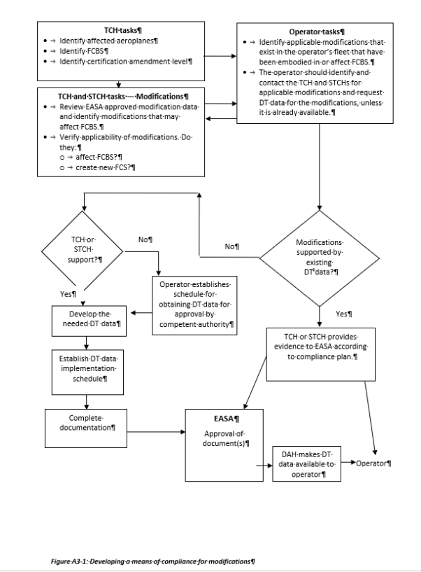
6.1. Contents of the maintenance programme
(a) The operator’s maintenance programme should contain or refer to an implementation plan that ensures that:
(1) all new repairs and modifications that affect FCBS will have DT data and DTI or other procedures implemented;
(2) all existing repairs and modifications to FCBS have been or will be evaluated for damage tolerance and have DTI or other procedures implemented. In the context of this implementation plan, there should be a process that:
(i) reviews operator processes to determine if DT data for repairs and modifications affecting FCBS have been developed and incorporated into the operator’s maintenance programme for the operational life of the aircraft. If an operator is able to demonstrate that these processes ensure that DT data is developed for all repairs and modifications affecting FCBS, then no further action is required for existing repairs and modifications.
(ii) identifies or surveys existing repairs (using the applicable REGs or survey parameters from Annex 2 to this Appendix) and modifications that affect FCBS and obtain and implement DTI for those repairs and modifications. This should include an implementation schedule that provides timing for incorporation of the DT data into the operator’s maintenance programme, within the time frame given in the applicable TCH or STCH’s approved documentation.
(b) Figure A3-2 below outlines one possible means that an operator can use to develop an implementation plan for aircraft in their fleet.
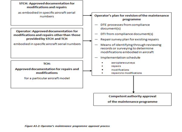
6.1.1. Implementation plan for repairs
Except as described in CS 26.370, the maintenance programme should include a repair survey schedule to identify repairs that may need DT data developed. The TCH’s REGs may be used as a basis for this plan. (See Paragraph 3.13 above and Annex 2 for further information)
6.1.2. Implementation plan and actions for modifications
(a) Points 26.307, 26.308, 26.333 and 26.334 of Part-26 require DAHs to develop DTI for existing modifications (design changes) within a certain timescale. CS 26.370 provides means of compliance to operators on how to revise the maintenance programme by including an implementation plan to show how approved DTI data will be obtained and used to address the potential adverse effects of repairs and modifications to FCS and submit it for approval to the competent authority. To show compliance with CS 26.370, operators are first requested to develop a list of modifications affecting FCBS through a review of the aircraft records. The operator will need to show to their competent authority that the aircraft records are a reliable means for identifying modifications that affect FCBS. The aircraft records, in conjunction with data provided by the DAH, may also be sufficient to help identify whether DTI exists for all modifications. However, for some older aircraft, a review of records alone may not always be adequate to identify all the modifications that have an adverse effect on FCBS, or be sufficient to establish whether a DTE has been accomplished and DTI is complete, without requesting such information from the DAH. Physical inspection of the aircraft may help establish the scope of the modification if it is unclear from the records. Finally, the aircraft survey for repairs may also identify modifications affecting FCS, which should then be evaluated and DTI obtained as necessary in accordance with CS 26.370(h).
(b) To support identification of modifications that need to be addressed, operators should — concurrently with the TCH and STCHs’ tasks — identify the TCH or STC or other approval holder-developed modifications that exist in their aircraft fleets. To support compliance with point 26.370 of Part-26 as envisaged in CS 26.370, operators should perform the following tasks:
(1) From the review of records, compile a listing of all TCH and STCH‑developed modifications that are currently installed on their fleet.
(2) Delete from the listing those modifications that do not affect FCBS. Documents from the TCH may be used to identify the FCBS.
Note: In order to ensure timely compliance with point 26.370 of Part‑26, operators should begin developing the list of modifications that affect FCBS, for each affected aircraft in the fleet, as soon as the TCHs make their FCBS listing available.
(3) The modifications that affect FCBS must be reviewed to determine whether:
(i) DT data already exists in the maintenance programme, or is available and is complete; or
(ii) DT data needs to be developed.
(4) For DT data that is complete, the operator should incorporate it into the maintenance programme and implement it according to the schedule provided in 6.1.3 or as otherwise agreed by the competent authority. Note: Complete DTI for STCs approved after 1 September 2003 should be available to operators not later than 30 months after the date of applicability of point 26.370 of Part-26 following approval by EASA unless the STCH no longer exists.
(5) For DT data that is not available or is incomplete 30 months after the date of applicability of point 26.370 of Part-26, the operator should ensure that the plan developed according to CS 26.370 will address each affected modification.
(6) Where DT data is not available or is incomplete, the operator should notify both the STCH or a third party that DT data for the modification is required.
(7) Establish whether the STCH or a third party will provide the data.
Note: For modifications addressed by point 26.334 of Part-26 (for change approvals issued before 1 September 2003), the DAH does not need to develop the DT data until requested by an operator and has 24 months from that date to submit the data for approval. It is therefore envisaged that DTI for these modifications will be addressed in accordance with paragraph (8) and the timescales of 26.370 (h). Whatever the approval date of the change, the operator is responsible for obtaining the DTI from the approval holder once it becomes available. It is therefore recommended that the operator contacts the approval holder or a third party as soon as possible after identifying a modification that affects FCBS to establish when the DTI will become available.
(8) For those modifications where the DTI will not be incorporated into the maintenance programme within 36 months from the date of applicability of point 26.370(a)(ii) of Part-26, the operator’s DT data implementation plan should contain the following information:
(i) a description of the modification;
(ii) the affected aircraft and the affected FCS;
(iii) the DSG of the affected aircraft;
(iv) a list of the FCS introduced by the modification (if it exists);
(v) the CS 25.571 certification level for determining the DT data;
(vi) a plan for obtaining DT data for each modification (e.g. reliance on the existing STCH or a formal contract with a Part 21‑Subpart J-approved third party) to produce DT data within a specified compliance time in accordance with CS 26.370;
(vii) a DT data implementation schedule for incorporating the DT data into the maintenance programme once it is received;
(viii) a means of ensuring that the aircraft will not be operated beyond the time limit established for obtaining DT data.
(9) For modifications that are found during the aircraft survey for repairs, the operator should ensure that DT data is obtained and submitted to EASA for approval. Once approved, the operator should incorporate the DTIs into its maintenance programme no later than 12 months from the date when the modification was identified.
6.1.3. Implementation of DTI
Operators should accomplish the first inspection of a change according to the approved DTI implementation schedule. If the age of the modification is unknown, the operator should use the aircraft age in total flight cycles or total flight hours, as applicable. Where there is any doubt about the applicability of the programme data or the timescales provided in the DAH documentation, EASA should be consulted by the operators and competent authorities concerned.
7. ROLE OF THE COMPETENT AUTHORITY
The competent authority’s role is to verify that the AMP is in compliance with point 26.370 of Part-26 and ensure that their aircraft continuing airworthiness monitoring survey programme takes into account the risks associated with potential non-compliance of operators’ or owners’ AMPs with the requirements of point 26.370 of Part-26. (Ref. Part-M requirements for the Competent Authority (M.B.301 and 303)).
[Amdt 20/2]
[Amdt 20/20]
Annex 1 to Appendix 3 to AMC 20-20 Approval process for new repairs
ED Decision 2020/023/R
The approval process for new repairs may use a three-stage approach, as now commonly used in the aviation industry.
DT data includes inspection requirements, such as the inspection threshold, inspection method, and inspection repetitive interval, or may specify a time limit when a repair or modification needs to be replaced or modified. The required data may be submitted all at once, prior to the aircraft’ s return to service, or it may be submitted in stages. The following three-stage approval process is available, which involves incremental approval of engineering data to allow an aircraft to return to service before all the engineering data previously described is submitted. The three stages are described as follows:
(a) The first stage is the approval of the static strength data and the schedule for submission of the DT data. This approval is required prior to returning an aircraft to service.
(b) The second stage is approval of the DT data. Sufficient data to substantiate continued safe operation should be submitted no later than 12 months after the aircraft was returned to service, unless a temporary limitation was substantiated by sufficient fatigue and damage tolerance evaluation data and approved at the first stage of approval, in which case the second stage DT data should be approved before the temporary limit is reached. At the second stage, the DT data need only contain the threshold when inspections are required to begin as long as a process is in place to develop the required inspection method and repetitive intervals before the threshold is reached. In this case, the submission and approval of the remaining DT data may be deferred to the third stage. The approved threshold acts as a limitation on the repair data.
(c) The third stage is approval of the inspection method and the repetitive intervals. This final element of the repair certification data in compliance with CS 25.571 should be submitted and approved prior to the inspection threshold being reached.
The applicant should inform the operator if this process is being used, and of the expected timelines for the delivery of the data. To follow the three-stage process, the DAHs subject to Part 21 will need to establish procedures to be accepted by EASA under their design organisation approvals.
[Amdt 20/2]
[Amdt 20/20]
Annex 2 to Appendix 3 to AMC 20-20A Assessment of existing repairs
ED Decision 2020/023/R
A DTI assessment process consists of an aircraft repair survey, identification and disposition of repairs requiring immediate action and development of damage-tolerance-based inspections, as described below:
1. AIRCRAFT REPAIR SURVEY
A survey will be used to identify existing repairs and repair configurations on all FCS and provide a means to categorise those repairs. The survey would apply to all affected aircraft in an operator’s fleet, as defined in the maintenance programme, using the process contained in the REGs or similar documents. The procedure to identify repairs that require DTE should be developed and documented using CS 25.571 and AMC 25.571 (dependent on aircraft certification level), together with additional guidance specific to repairs, such as:
(a) Size of the repair;
(b) Repair configuration:
(1) SRM standards,
(2) other;
(c) Proximity to other repairs; and
(d) Potential effect on FCS:
(1) inspectability (access and method),
(2) load distribution.
See Paragraph 4 of this Annex for more details.
2. IDENTIFICATION AND DISPOSITION OF REPAIRS REQUIRING IMMEDIATE ACTION
Certain repairs may not meet the minimum requirements because of cracking, corrosion, dents, or inadequate design. The operator should use the guidance provided in the compliance document to identify these repairs and, once they are identified, take appropriate corrective action. In some cases, modifications may need to be made before further flights. The operator should consider establishing a fleet campaign if similar repairs may have been installed on other aircraft.
3. DAMAGE TOLERANCE INSPECTION DEVELOPMENT
This includes the development of the appropriate maintenance plan for the repair under consideration. During this step determine the inspection method, threshold, and repeat interval. Determine this information from existing guidance information as documented in the RAG (see Paragraph 4), the REGs or from the results of an individual DTE performed using the guidance in AMC 25.571. Then determine the feasibility of an inspection programme to maintain continued airworthiness. If the inspection programme is practical, incorporate the DTI into the individual aircraft maintenance programme. If the inspection is either impractical or impossible, incorporate a replacement time for the repair into the individual aircraft maintenance programme. The three-stage approach discussed in Annex 1 to this Appendix may be used, if appropriate.
4. REPAIR ASSESSMENT GUIDELINES
4.1. Criteria to assist in developing the repair assessment guidelines
The following criteria are those developed for the fuselage pressure boundary, similar to those found in FAA AC 120-73 and previous JAA and EASA documentation. DAHs may find it appropriate to develop similar practices for other types of aircraft and areas of the structure.
The purpose is to develop repair assessment guidelines requiring specific maintenance programmes, if necessary, to maintain the damage tolerance integrity of the repaired airframe. The following criteria have been developed to assist in the development of that guidance material:
(a) Specific repair size limits for which no assessment is necessary may be selected for each model of aircraft and structural location. This will enable to minimise the burden on the operator while ensuring that the aircraft’s baseline inspection programme remains valid.
(b) Repairs that are not in accordance with SRM must be reviewed and may require further action.
(c) Repairs must be reviewed where the repair has been installed in accordance with SRM data that has been superseded or rendered inactive by new damage-tolerant designs.
(d) Repairs in close proximity to other repairs or modifications require review to determine their impact on the continued airworthiness of the aircraft.
(e) Repairs that exhibit structural distress should be replaced before further flights.
4.2. Repair assessment methodology
The next step is to develop a repair assessment methodology that is effective in evaluating the continued airworthiness of existing repairs for the fuselage pressure boundary. Older aircraft models may have many structural repairs, so the efficiency of the assessment procedure is an important consideration. In the past, evaluation of repairs for damage tolerance would require direct assistance from the DAH. Considering that each repair design is different, that each aircraft model is different, that each area of the aircraft is subjected to a different loading environment, and that the number of engineers qualified to perform a damage tolerance assessment is small, the size of an assessment task conducted in that way would be unmanageable. Therefore, a new approach has been developed as an alternative.
Since repair assessment results will depend on the model-specific structure and loading environment, the DAHs should create an assessment methodology for the types of repairs expected to be found on each affected aircraft model. Since the records on most of these repairs are not readily available, locating the repairs will necessitate surveying the structure of each aircraft. A survey form is created by the DAH that may be used to record key repair design features needed to accomplish a repair assessment. Airline personnel not trained as damage tolerance specialists can use this form to document the configuration of each observed repair.
Some DAHs have developed simplified methods using the information from the survey form as input data, to determine the damage tolerance characteristics of the surveyed repairs. Although the repair assessments should be performed by well-trained personnel familiar with the model-specific repair assessment guidelines, these methods enable appropriate staff, not trained as damage tolerance specialists, to perform the repair assessment without the assistance of the TCH. This methodology should be generated by the aircraft TCH. Model-specific repair assessment guidelines will be prepared by the TCHs.
From the information on the survey form, it is also possible to classify repairs into one of three categories:
|
Category A: |
A permanent repair for which the baseline zonal inspection (BZI) (typical maintenance inspection intervals assumed to be performed by most operators) is adequate to ensure continued airworthiness. |
|
Category B: |
A permanent repair that requires supplemental inspections to ensure continued airworthiness. |
|
Category C: |
A temporary repair that will need to be reworked or replaced prior to an established time limit. Supplemental inspections may be necessary to ensure continued airworthiness prior to this limit. |
When the LOV of the maintenance programme is extended, the initial categorisation of repairs may need a review by the applicant for the LOV extension, and the operator may need to ensure that these remain valid up to the new LOV.
4.3. Repair assessment process
There are two principal techniques that can be used to accomplish the repair assessment. The first technique involves a three-stage procedure. This technique could be well-suited for operators of small fleets. The second technique involves the incorporation of the repair assessment guidelines as part of an operator’s routine maintenance programme. This approach could be well-suited for operators of large fleets and would evaluate repairs at predetermined planned maintenance visits as part of the maintenance programme.
The first technique generally involves the execution of the following three stages (see Figure A3(2)-1):
Stage 1: Data collection
This stage specifies what structure should be assessed for repairs and collects data for further analysis. If a repair is on a structure in an area of concern, the analysis continues, otherwise the repair does not require classification per this programme.
Repair assessment guidelines for each model will provide a list of structure for which repair assessments are required. Some DAHs have reduced this list by determining the inspection requirements for critical details. If the requirements are equal to normal maintenance checks (e.g. BZI checks), those details may be excluded from this list.
Repair details are collected for further analysis in Stage 2. Repairs that do not meet the minimum design requirements or are significantly degraded are immediately identified, and corrective actions must be taken before further flights.
Stage 2: Repair categorisation
The repair categorisation is accomplished by using the data gathered in Stage 1 to answer simple questions regarding structural characteristics.
If the maintenance programme is at least as rigorous as the BZI identified in the TCH’s model-specific repair assessment guidelines, well-designed repairs in good condition meeting size and proximity requirements are Category A. Simple condition and design criteria questions are provided in Stage 2 to define the lower bounds of Category B and C repairs. The process continues for Category B and C repairs.
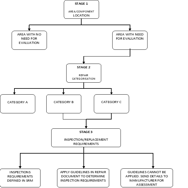
Figure A3(2)-1: Repair assessment stages
Stage 3: Determination of structural maintenance requirements
The specific supplemental inspection and/or replacement requirements for Category B and C repairs are determined in this stage. Inspection requirements for the repair are determined by calculation or by using predetermined values provided by the DAH, or other values obtained using an EASA-approved method.
In evaluating the first supplemental inspection, Stage 3 will define the inspection threshold in flight cycles measured from the time of the repair installation. If the time of the repair installation is unknown and the aircraft has exceeded the assessment implementation times or has exceeded the time for first inspection, the first inspection should occur by the next ‘C-check’ interval, or equivalent cycle limit after the repair data is gathered (Stage 1).
The operator may choose to accomplish all three stages at once, or just Stage 1. In the latter case, the operator would be required to adhere to the schedule specified in the EASA‑approved model-specific repair assessment guidelines for completion of Stages 2 and 3. Incorporating the maintenance requirements for Category B and C repairs into an operator’s individual aircraft maintenance or inspection programme completes the repair assessment process for the first technique.
The second technique would involve setting up a repair maintenance programme to evaluate all the applicable structures as detailed in paragraph 1 at each predetermined maintenance visit to confirm that they are permanent. This technique would require the operator to choose an inspection method and interval in accordance with the EASA‑approved repair assessment guidelines. The repairs whose inspection requirements are fulfilled by the chosen inspection method and interval would be inspected in accordance with the approved maintenance programme. Any repair that is not permanent, or whose inspection requirements are not fulfilled by the chosen inspection method and interval, would either be:
(a) upgraded to allow utilisation of the chosen inspection method and interval; or
(b) individually tracked to account for the repair’s unique inspection method and interval requirements.
This process is then repeated at the chosen inspection interval.
Repairs added between the predetermined maintenance visits, including interim repairs installed at remote locations, would be required either to have a threshold greater than the length of the predetermined maintenance visit or to be tracked individually to account for the repair’s unique inspection method and interval requirements. This would ensure the airworthiness of the structure until the next predetermined maintenance visit, at which time the repair would be evaluated as part of the repair maintenance programme.
5. MAINTENANCE PROGRAMME CHANGES
When a maintenance or inspection programme interval is revised, the operator should evaluate the impact of the change on the repair assessment programme. If the revised maintenance or inspection programme intervals are greater than those in the BZI, the previous classification of Category A repairs may become invalid. The operator may need to obtain approval of an alternative inspection method, upgrade the repair to allow utilisation of the chosen inspection method and interval, or re-categorise some repairs and establish unique supplemental inspection methods and intervals for specific repairs. Operators using the ‘second technique’ of conducting repetitive repair assessments at predetermined maintenance visits would evaluate whether the change to the predetermined maintenance visit continues to fulfil the repair inspection requirements.
6. SRM UPDATE
The general section of each SRM will contain brief descriptions of damage tolerance considerations, categories of repairs, description of BZIs, and the repair assessment logic diagram. In updating each SRM, existing location-specific repairs should be labelled with appropriate repair category identification (A, B or C), and specific inspection requirements for B and C repairs should also be provided as applicable. SRM descriptions of generic repairs will also contain repair category considerations regarding size, zone, and proximity. Detailed information for the determination of inspection requirements will have to be provided for each model. Repairs which were installed in accordance with a previous revision of the SRM, but which have now been superseded by a new damage-tolerant design, will require review. Such repairs may be reclassified to Category B or C, requiring additional inspections and/or rework.
7. STRUCTURE MODIFIED BY AN STC
The current repair assessment guidelines provided by the TCH are not always applicable to structure modified by an STC. Nonetheless, it is expected that all the structure modified by an STC should be evaluated by the operator and, if possible, in conjunction with the STCH. Point 26.370 of Part-26 requires the operator to amend their maintenance programme to address all such repairs, and a conservative extension of the TCH’s REGs to all STCs containing FCS can be envisaged to ensure that all repairs to FCS are identified. Subsequently, each repair can be subjected to a DTE, and DTI be provided with the support of a DAH. The STCH should conduct specific damage tolerance assessments of known published repairs (SRM, SBs, etc.) and provide appropriate instructions to the operator.
It is expected that the STCH will assist the operators by preparing the required documents. If the STCH is no longer in business, or is otherwise unable to provide assistance, the operator would have to acquire the EASA-approved guidelines independently. Ultimately, the operator remains responsible for the continued safe operation of the aircraft.
[Amdt 20/2]
[Amdt 20/20]
Annex 3 to Appendix 3 to AMC 20-20A Repairs and modifications to removable structural components
ED Decision 2020/023/R
1. DETERMINING THE AGE OF A REMOVABLE STRUCTURAL COMPONENT
Determining the actual component’s age or assigning a conservative age provides flexibility and reduces operator burden when implementing DT data for repairs and modifications to structural components. In some cases, the actual component’s age may be determined from records. If the actual age cannot be determined this way, the component’s age may be conservatively assigned using one of the following fleet leader concepts, depending upon the origin of the component:
(a) If component times are not available, but records indicate that no part changes have occurred, aircraft flight cycles or flight hours can be used.
(b) If no records are available, and the parts could have been switched from one or more older aircraft under the same maintenance programme, it should be assumed that the time on any component is equal to the oldest aircraft in the programme. If this is unknown, the time should be assumed to be equal to the same model aircraft that is the oldest or has the most flight cycles or flight hours in the world fleet.
(c) A manufacturing date marked on a component may also be used to help establish the component’s age in flight cycles or flight hours. This can be done by using the above reasoning and comparing it to aircraft in the affected fleet with the same or older manufacturing date.
If none of these options can be used to determine or assign a component age or total number of flight cycles or flight hours, a conservative implementation schedule can be established by using the guidelines applied in paragraph 3 of this Appendix, for the initial inspection, if required by the DT data.
2. TRACKING
An effective control or tracking system should be established for removable structural components that are identified as FCBS or that contain FCS. This will help ensure compliance with the maintenance programme’s requirements specific to repairs and modifications installed on an affected removable structural component. Paragraph 4 of this Appendix provides options that could be used to alleviate some of the burden associated with tracking all repairs to affected removable structural components.
3. DEVELOPING AND IMPLEMENTING DT DATA
(a) Repairs
Accomplish the initial repair assessment of the affected structural component at the same time as the aircraft level repair survey for the aircraft on which the component is installed. Develop the DT data according to the process given in Annex 2 and incorporate DTI into the maintenance programme.
(b) Modifications
Accomplish the initial modification assessment of the affected structural component at the same time as the aircraft level modification assessment for the aircraft on which the component is installed. Develop DT data and incorporate the DTI into the maintenance programme.
If the actual age of the repairs or modifications installation, or the total number of flight cycles or flight hours is known, use that information to establish when the initial inspection of the component should be performed. Repeat the inspection at the intervals provided by the TCH or STCH for the repair or modification against the component.
If the actual age of the repairs or modifications installation, or the total number of flight cycles or flight hours is unknown, but the component’s age or total number of flight cycles or flight hours is known, or can be assigned conservatively, use the component’s age, or the total number of flight cycles or flight hours to establish when the initial inspection of the component should be performed. Repeat the inspection at the intervals provided by the TCH or STCH for the repairs and modifications against the component.
As an option, accomplish the initial inspection on the affected component at the next C‑check (or equivalent interval) following the repair assessment. Repeat the inspection at the intervals provided by the TCH or STCH for the repairs and modifications against the component.
4. EXISTING REPAIRS AND MODIFICATIONS — COMPONENTS RETRIEVED FROM STORAGE
(a) If the time on the component (in flight cycles or flight hours) is known, or can be conservatively assigned, perform the following:
(1) survey the component;
(2) dispose repairs and modifications;
(3) implement any DTI in accordance with the approved schedule;
(4) accomplish the initial inspection using the actual age of the repairs or modifications, or the total number of flight cycles or flight hours, if known. If the age of the repairs or modifications is not known, use the component’s age. Repeat the inspection at the intervals given for the repairs or modifications against the component.
(b) If the time on the component (in flight cycles or flight hours) is unknown and cannot be conservatively assigned, perform the initial repair or modification assessment of the affected component prior to installation, and perform the following actions:
(1) develop DT data according to the process given in paragraph 3 or 4 of Appendix 3 to this AMC as applicable;
(2) incorporate any DTI into the maintenance programme;
(3) accomplish the first inspection on the affected component at the next C‑check (or equivalent interval) following the repair or modification assessment;
(4) repeat the inspection at the intervals given for the repair or modification against the component.
5. IMPLEMENTATION OPTIONS TO HELP REDUCE TRACKING BURDEN
The following implementation techniques could be used to alleviate some of the burden associated with tracking repairs to affected removable structural components. These techniques, if used, would need to be included in the maintenance programme and may require additional EASA approval and TCH or STCH input for DTI.
(a) Upgrading existing repairs
As an option, existing repairs may be removed and replaced with new parts of the same design revised as necessary to support the new installation. This practice would permit the DTI requirements of the repair to be set to zero and to re-establish an initial tracking point for the repair. Normally, this would be done at or before the survey for maximum benefit. The initial and repetitive inspections for the upgraded repair would then be accomplished at the intervals given for the repair against the component.
A repair could also be upgraded to one whose inspection requirements and methods are already fulfilled by an operator’s maintenance or inspection programme. That repair would then be repetitively inspected at each routine inspection interval applicable to the repair. Specific tracking would not be required because that area of the aircraft would have already been normally inspected on each aircraft in the fleet as part of the existing approved maintenance programme. If the operator’s programme intervals were changed, the effect on requirements for specific tracking would have to be re-evaluated.
(b) Special initial and/or routine inspections
As an option, existing repairs may have special initial inspections accomplished during the component survey. This initial inspection establishes an initial tracking point for the repair. Following this initial inspection, the DTI requirements (e.g. repetitive inspections) of the repair would be implemented.
In addition, special routine inspections could be defined for typical repairs that could be applied at a normal interval. In this case, an operator could check the affected components on each aircraft for this type of a repair at the defined interval. If the repair is found, the special inspection would be applied to ensure its airworthiness until the next scheduled check. This alleviates the need to specifically track affected components for every repair, especially typical ones.
[Amdt 20/2]
[Amdt 20/20]
Annex 4 to Appendix 3 to AMC 20-20A Service bulletin review process
ED Decision 2020/023/R
Guidelines for following the service bulletin (SB) flow chart
Note: While it is believed that this guidance is fairly comprehensive, it may not address every possible situation. It is therefore incumbent on the user to use good judgement and rationale when making any determination.
Screening SBs to determine which ones require DT data is primarily a TCH responsibility.
The result of this screening is a list of SBs which require special directed inspections to ensure continued airworthiness. SBs included in the list will be grouped into Type I and Type II SBs. Type I SBs have existing DT data and Type II SBs require developing DT data. The list is not comprehensive and will not include all the SBs associated with an aircraft. The list does not need to include those SBs where the inspection programme developed for the repair assessment programme has been determined to be sufficient to meet the damage tolerance requirements for the FCBS that is affected by the SB.
To ensure compliance with Part-26, any DTI identified in the existing programme that is required to continue to be implemented to satisfy point 26.370 should be identified as such in the ICA.
Query 1 Does the SB address a structural repair or a modification to FCS?
Historically, any SB, service letter or other document that lists ATA Chapters 51 through 57 could provide repair or modification instructions that may require DT data. In addition, certain repairs or modifications accomplished under other ATA chapters may affect FCS. The first step in the screening process is to identify all such service instructions and develop a list of candidates for review (Q2).
Query 2 Does the service instruction specify either a repair or modification that creates or affects FCS?
If it does, then the service instruction requires further review (Q3). If it does not, then the service instruction does not require further review.
Query 3 Is the service instruction mandated?
SBs and other service instructions that are mandated by an AD have requirements to ensure inspection findings (e.g., detected cracks or other structural damage/degradation) are addressed in an approved manner. If the TCH can demonstrate that it applies a process for developing inspection programmes for mandated SBs using DT data and/or service-based inspection results, and for continuously reviewing the SBs for their adequacy to detect cracks in a timely manner, the mandated SBs should then be considered as compliant with the intent of this process. Otherwise, the TCH will need to demonstrate that the inspection programme in the mandated SB has been developed using DT data and/or appropriate service-based inspection results. The outcome of Query 3 branches to two unrelated boxes (Q4: if mandated by an AD, or Q7: if not mandated by an AD).
Query 4 Does the SB or service instruction contain terminating action?
Query 3 established that the inspection programme for the baseline configuration is acceptable.
Query 5 Does the terminating action have DT data?
If the terminating action has a documented continuing airworthiness inspection programme based on damage tolerance principles, then no further review is required. The SB should be documented in the list. If the terminating action does not have DT data, or the status of the inspection programme cannot be verified, then further review is necessary (Q6).
Query 6 Does the SB address a safe-life part?
If it does, no further action is required. Otherwise, damage-tolerance-based inspections will need to be developed and provided to the operators. The SB should be included in the list along with where to find the required continued airworthiness inspection programme.
Query 7 In Query 3 a structural SB that was mandated by AD was identified.
Query 7 asks if a one-time inspection is required to satisfy the intent of the requirement. If it does, it is deemed that this is being done to verify that a condition does not exist and, on finding that condition, correct that condition to baseline configuration. As such, normal SSID programmes would then be expected to cover any required continued airworthiness inspections. If a repair is necessary, it is further assumed that this was done by reference to the SRM or other suitable means. No further action is required if this is the case and, if a repair was necessary, other means exist to determine the required DT data. If no inspections or multiple inspections are required, additional evaluation is required (Q8).
Query 8 Is this a major structural design change (e.g. modification)?
This is a TCH decision that is part of the original certification process and is not a major/minor repair decision. If it is not a major design change, then proceed to Q10; if not, proceed to Q9.
Query 9 Does the change require NDIs to verify the integrity of the structure or are normal routine maintenance inspections sufficient?
This is a subjective question and may require re-evaluating the change and determining where specific fatigue cracking might be expected. If normal maintenance inspections are adequate, no further action is required. Otherwise, proceed to Q10.
Query 10: Does the SB contain DT data for both the baseline and modified aircraft configurations?
If so, the SB is satisfactory. Otherwise, damage-tolerance-based inspections will need to be developed and provided to the operators. The SB should be documented in the list along with where to find the required continued airworthiness inspection programme.
SB screening procedure
1. The TCH will perform the screening and the Structures Task Group will validate the results.
2. A list of all SBs requiring action will be included in the TCH compliance document. Those not requiring action will not be included in the list.
3. SBs included in the list will fall into one of two general types:
Type I — SBs which have existing DT data.
Type II — SBs that require developing DT data.
4. TCH actions:
Type I — No action required.
Type II — Develop DT data and make it available to operators.
5. Operator actions (apply to both SB types):
— Review SB incorporation on a tail number basis.
— For incorporated SBs that rely on BZI (i.e. no special inspections required based on DTE performed), reconcile any maintenance planning document structural inspection escalations.
— For incorporated SBs that require DTI, verify that DTI has been included in the operations specification and include it if it is missing.
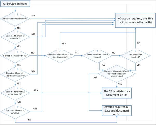
Figure A3(4)-1: SB flow chart
[Amdt 20/2]
[Amdt 20/20]
Annex 5 to Appendix 3 to AMC 20-20A List of major changes and STCs that may adversely affect fatigue-critical structure
ED Decision 2020/023/R
(1) Passenger-to-freighter conversions (including addition of main deck cargo doors).
(2) Gross weight increases (increased operating weights, increased zero fuel weights, increased landing weights, and increased maximum take-off weights).
(3) Installation of fuselage cut-outs (passenger entry doors, emergency exit doors or crew escape hatches, fuselage access doors, and cabin window relocations).
(4) Complete re-engine or pylon modifications.
(5) Engine hush kits.
(6) Wing modifications such as installing winglets or changes in flight control settings (flap droop), and modification of wing trailing edge structure.
(7) Modified skin splices.
(8) Antenna installations.
(9) Any modification that affects several stringer or frame bays.
(10) Any modification that covers structure requiring periodic inspection by the operator’s maintenance programme.
(11) Any modification that results in operational mission change that significantly changes the manufacturer’s load or stress spectrum (e.g. passenger-to-freighter conversion).
(12) Any modification that changes areas of the fuselage that prevents external visual inspection (e.g. installation of a large external fuselage doubler that results in hiding details beneath it).
(13) In general, attachment of interior monuments to FCS. Interior monuments include large items of mass such as galleys, closets, and lavatories.
[Amdt 20/2]
[Amdt 20/20]
Annex 6 to Appendix 3 to AMC 20-20A Background to the need for damage-tolerance-based inspection programmes for repairs
ED Decision 2020/023/R
Repairs are a concern on older aircraft because of the possibility that they may develop, cause, or obscure metal fatigue, corrosion, or other damage during service. This damage might occur within the repair itself or in the adjacent structure, and might ultimately lead to structural failure.
In general, repairs present a more challenging problem to solve than the original structure because they are unique and tailored in design to correct particular damage to the original structure. While the performance of the original structure may be predicted from tests and from experience on other aircraft in service, the behaviour of a repair and its effect on the fatigue characteristics of the original structure are generally known to a lesser extent than for the basic unrepaired structure.
Repairs may be of concern as time in service increases for the following reasons:
As aircraft age, both the number and age of the existing repairs increase. Along with this increase is the possibility of unforeseen repair interaction, failure, or other damage occurring in the repaired area. The continued operational safety of these aircraft depends primarily on a satisfactory maintenance programme (with inspections conducted at the right time, in the right place, using the most appropriate technique, or in some cases, replacement of the repair). To develop this programme, a DTE of repairs to aircraft structure is essential. The longer an aircraft is in service, the more important this evaluation and a subsequent inspection programme become.
The practice of repair justification has evolved gradually over the last 20 years. Some repairs described in the aircraft manufacturers’ SRMs were not designed in accordance with fatigue and damage tolerance principles (Ref. AAWG Report: Recommendations concerning ARAC taskings FR Doc 04‑10816; Aging Aircraft Safety Final Rule. 14 CFR 121.370a and 129.16.). Repairs accomplished in accordance with the information contained in the early versions of the SRMs may require additional inspections if evaluated using the fatigue and damage tolerance methodology.
Damage tolerance is a structural design and inspection methodology used to maintain safety by considering the possibility of metal fatigue or other structural damage (i.e. safety is maintained by adequate structural inspection until the damage is repaired). One prerequisite for the successful application of the damage tolerance approach for managing fatigue is that crack growth and residual strength can be anticipated with sufficient precision to allow inspections to be established that will detect cracking before it reaches a size that will degrade the strength to less than a specified level. A DTE entails the prediction of sites where fatigue cracks are most likely to initiate in the aircraft’s structure, the prediction of the crack path and rates of growth under repeated aircraft structural loading, the prediction of the size of the damage at which strength limits are exceeded, and an analysis of the potential opportunities for inspection of the damage as it progresses. This information is used to establish an inspection programme for the structure that will be able to detect cracking that may develop before it could contribute to a catastrophic failure.
The evidence to date is that when all the critical structure is included, damage-tolerance-based inspections and procedures, including modification and replacement, provide the best assurance of continued structural integrity that is currently available. In order to apply this concept to existing transport aeroplanes, the competent authorities have issued a series of ADs requiring compliance with the first supplemental inspection programmes resulting from the application of this concept to existing aeroplanes. Generally, these ADs require that operators incorporate SSIDs into their maintenance programmes for the affected aeroplanes. These documents were derived from damage tolerance assessments of the originally certified type designs for these aeroplanes. For this reason, the majority of ADs written for the SSIP did not attempt to address the issues related to the damage tolerance of repairs that had been made to the aeroplanes. The objective of repair assessment and repair evaluation guidelines is to provide the same level of assurance for areas of the structure that have been repaired as that achieved by the SSIP for the baseline structure as originally certified.
[AMC 20/20]
Appendix 4 to AMC 20-20A Guidelines for the development of a corrosion prevention control programme
ED Decision 2020/023/R
1. GENERAL
The TCH should develop a baseline CPCP, which should be reviewed by EASA. The baseline CPCP is intended to facilitate the development of a CPCP by an operator for their maintenance programme.
The operator should include a CPCP in the maintenance programme, and where a TCH baseline CPCP exists, it should be taken into account in the development of the operator’s CPCP. The operator should show that the CPCP is comprehensive in that it addresses all the corrosion likely to affect primary structure, and is systematic in that:
(a) it provides step-by-step procedures that are applied on a regular basis to each identified task area or zone, and
(b) these procedures are adjusted when they result in evidence that corrosion is not being controlled to an established acceptable level (Level 1 or better).
1.1 Purpose
This Appendix gives guidance to operators and DAHs who are developing and implementing a CPCP for aeroplanes maintained in accordance with an aircraft maintenance programme developed in compliance with point M.A.302 of Part-M.
CPCPs have been developed by the DAH with the assistance of aircraft operators and competent authorities. They relied heavily on service experience to establish CPCP implementation thresholds and repeat intervals. Since that time a logical evaluation process has been developed to ensure environmental damage is considered in the evaluation of aircraft structure. This process is identified in ATA MSG-3 Scheduled maintenance development document, which introduced the CPCP concept in revision 2, circa 1993.
1.2 Approval
Approval of a TCH CPCP may either be through the MRB (ISC) using existing procedures for EASA MRBR approval, or directly by EASA if no EASA-approved MRBR exists for the type. Provided that the operator has an NAA-approved aircraft maintenance programme (AMP) that controls corrosion to Level 1 or better, the operator need not follow exactly the programme offered by the TCH. However, revisions to the TCH’s approved programme should be considered by the operator for incorporation in the operator’s MP under the Part-M requirements.
2. DEFINITIONS
— Allowable Limit: this is the amount of material (usually expressed in the thickness of the material) that may be removed or blended out without affecting the ultimate design strength capability of the structural member. Allowable limits may be established by the TCH/DAH. EASA may also establish allowable limits. The DAH normally publishes allowable limits in the SRM or in SBs. Note: This revision of the AMC amends the definition of corrosion levels such that the concept of local and widespread corrosion is no longer specified. Nonetheless, when deriving allowable limits for the structure and the adjacent structure, the full extent of the damage and material removed in the finding and the previous findings affecting the same areas must be taken into account. Applicable fatigue and damage tolerance requirements must be taken into account when establishing the allowable limits.
— Baseline CPCP: this is a CPCP developed for a specific model aeroplane. The TCH typically develops the baseline CPCP (see TCH-developed baseline CPCP below). It contains the corrosion inspection tasks, an implementation threshold, and a repeat interval for task accomplishment in each area or zone.
— Basic task(s): this is a specific and fundamental set of work elements that should be performed repetitively in all task areas or zones to successfully control corrosion. The contents of the basic task may vary depending upon the specific requirements in an aeroplane area or zone. The basic task is developed to protect the primary structure of the aeroplane.
— Corrosion prevention and control programme (CPCP): this is a comprehensive and systematic approach to controlling corrosion in such a way that the load carrying capability of an aircraft structure is not degraded to less than a level necessary to maintain airworthiness. It is based upon the baseline CPCP described above. A CPCP consists of a basic corrosion inspection task, task areas, defined corrosion levels, and compliance times (implementation thresholds and repeat intervals).
The CPCP also includes procedures to notify the competent authority of the findings and data associated with Level 2 and Level 3 corrosion and the actions taken to reduce future findings to Level 1.
— Implementation threshold (IT): this is the aircraft age associated with the first time the basic corrosion inspection task should be accomplished in an area or zone.
— Level 1 corrosion is:
Damage occurring between successive inspections that is within the allowable damage limits; or
Damage occurring between successive inspections that does not require structural reinforcement, replacement or new damage-tolerance-based inspections; or
Corrosion occurring between successive inspections that exceeds the allowable limits but can be attributed to an event not typical of operator usage of other aircraft in the same fleet; or
Light corrosion occurring repeatedly between inspections that eventually requires structural reinforcement, replacement, or new damage-tolerance-based inspections.
— Level 2 corrosion is any corrosion finding that exceeds Level 1, requiring a review of the operator’s CPCP effectiveness, but that is not determined to be Level 3.
The operator is responsible for making the initial determination of the corrosion level, and this may subsequently be adjusted based on consultation with the DAH.
A finding of Level 2 corrosion requires repair, reinforcement, or complete or partial replacement of the applicable structure, or revised fatigue and damage tolerance inspections.
Note: A statement of fact in previously mandated CPCPs states: corrosion findings that were discovered during the corrosion inspection task accomplished at the implementation threshold, and which require repair, reinforcement, or complete or partial replacement of the applicable structure, should not be used as an indicator of the effectiveness of the operator’s CPCP. The argument is that an operator’s corrosion programme effectiveness can only be determined after a repeat inspection has been performed in a given inspection task area. This argument is valid for aircraft with mandated CPCPs introduced after the aircraft has been in service for a number of years without a CPCP. This argument, however, is not valid for aircraft that have been maintained since entry into service using a CPCP that takes into account the TCH baseline CPCP and environmental deterioration (ED) programme. Consequently, corrosion findings exceeding Level 1 found on the corrosion inspection task implementation threshold may indicate that the threshold has been set too high and action should be taken to adjust the implementation threshold.
— Level 3 corrosion is that corrosion occurring during the first or subsequent accomplishments of an inspection task that the operator or subsequently the TCH or competent authority determines to be an urgent airworthiness concern.
Note: If Level 3 corrosion is determined at the implementation threshold or any repeat inspection, then it should be reported. Any corrosion that is more than the maximum acceptable to the DAH or EASA must be reported in accordance with the current regulations. This determination should be conducted jointly with the DAH.
— Light corrosion is corrosion damage so slight that removal and blend-out over multiple repeat intervals may be accomplished before material loss exceeds the allowable limit.
— Local corrosion. Generally, local corrosion is corrosion of a skin or web (wing, fuselage, empennage or strut) that does not exceed one frame, stringer, or stiffener bay. Local corrosion is typically limited to a single frame, chord, stringer or stiffener, or corrosion of more than one frame, chord, stringer or stiffener where no corrosion exists on two adjacent members on each side of the corroded member.
— Operator-developed programme. In order to operate an aeroplane in compliance with the maintenance programme of Part-M and Part-26, an operator should include in their maintenance or inspection programme an approved CPCP. An operator may adopt the baseline CPCP provided by the DAH or they may choose to develop their own CPCP, or may be required to if none is available from the DAH. In developing their own CPCP, an operator may join with other operators and develop a baseline CPCP similar to a TCH‑developed baseline CPCP for use by all operators in the group. The advantages of an operator-developed baseline CPCP are that it provides a common basis for all operators in the group to develop their CPCP and it provides a broader experience base for development of the corrosion inspection tasks and identification of the task areas.
— Repeat Interval (RI): this is the calendar time between the accomplishment of successive corrosion inspection tasks for a task area or zone.
— Task area: this is a region of aircraft structure to which one or more corrosion inspection tasks are assigned. The task area may also be referred to as a zone.
— TCH-developed baseline CPCP. The baseline CPCP may be developed as an integral part of the ICA or in a stand-alone section or manual. The TCH should provide an inspection programme that includes the frequency and extent of inspections necessary to ensure the continued airworthiness of the aircraft. Furthermore, the programme should include the information needed to apply protective treatments to the structure after inspection. In order for the inspections to be effectively accomplished, the TCH should include, in the ICA, corrosion removal and cleaning procedures and reference allowable limits. The baseline CPCP is intended to facilitate the operator’s development of a CPCP for their maintenance programme.
— Urgent airworthiness concern: this is damage that could jeopardise continued safe operation of any aircraft. An urgent airworthiness concern typically requires correction before the next flight and expeditious action to inspect the other aircraft in the operator’s fleet.
— Widespread corrosion: this is corrosion of two or more adjacent skin or web bays (a web bay is defined by frame, stringer or stiffener spacing). Or widespread corrosion is corrosion of two or more adjacent frames, chords, stringers, or stiffeners. Or widespread corrosion is corrosion of a frame, chord, stringer, or stiffener and an adjacent skin or web bay.
— Zone. See ‘Task area’.
3. DEVELOPMENT OF A BASELINE CPCP
3.1. Baseline CPCP
The objective of a baseline CPCP is to establish requirements for control of corrosion of aircraft structure to Level 1 or better for the operational life of the aircraft. The baseline CPCP should include the basic task, implementation thresholds, and repeat intervals. The baseline CPCP should also include procedures to notify the competent authority of the findings and data associated with Level 2 and Level 3 corrosion and the actions taken to reduce future findings to Level 1.
3.1.1. Baseline CPCP considerations
To establish an effective baseline CPCP, consideration of the following is necessary:
(a) the flight and maintenance history of the aircraft model and perhaps similar models;
(b) the corrosion properties of the materials used in the aircraft structure;
(c) the protective treatments used;
(d) the general practice applied during construction and maintenance; and
(e) local and widespread corrosion* (see Figure A4-1).
* Note: In some existing CPCPs, the concept of local and widespread corrosion is directly related to the corrosion level definitions, and for those programmes, those definitions remain applicable. The alignment of a programme with the corrosion level definitions of this amendment of the AMC may require a reassessment of the allowable limits and the way they are presented in the applicable ICA. This is because the assumptions made to determine the allowable limits may not have taken into account the fatigue and damage tolerance requirements that are now applicable through retroactive rulemaking and the updated certification basis. In addition, programmes that addressed widespread corrosion within the allowable limits as Level 2 corrosion may have addressed the derivation of the allowable limits without assuming that the maximum material loss would occur over the whole area.
When determining the detail of the corrosion inspection tasks, the implementation threshold and the repeat interval, a realistic operational environment should be considered. Technical representatives of both the TCH and the operators should participate in evaluating the service history and operational environment for the aircraft model. For new aircraft models and for aircraft models that have been in operation for only a short time, technical representatives of operators of similar aircraft models should be invited to participate.
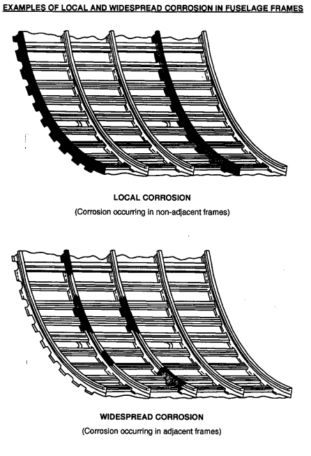
Figure A4-1
3.1.2. TCH-developed baseline CPCP
During the design development process, the TCH should provide a baseline CPCP as part of the ICA. The TCH initially evaluates the service history of corrosion available for aircraft of similar design used in the same operational environment. Where no similar design with service experience exists, those structural features concerned should be assessed using the environmental damage approach of ATA MSG-3. The TCH develops a preliminary baseline CPCP based on this evaluation. The TCH then convenes a working group consisting of operator technical representatives and representatives of the participating competent authorities. The working group reviews the preliminary baseline CPCP to assure that the tasks, implementation thresholds and repeat intervals are practical and assure the continued airworthiness of the aircraft. Once the working group review is complete, the TCH incorporates the baseline CPCP into the ICA (see Figure A4-2).
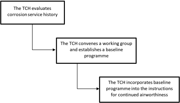
Figure A4-2: TCH-developed baseline CPCP
3.1.3 Operator-developed CPCP
Exceptionally, there may be instances where the TCH does not provide a baseline CPCP. In such instances, an operator may develop their CPCP without using a baseline CPCP, as long as the operator-developed CPCP is consistent with the requirements. It would be beneficial for an operator developing its own CPCP to consult other operators of the same or similar aircraft models in order to broaden the service experience available for use in preparing their programme. When a TCH‑prepared baseline CPCP is unavailable, a group of operators may prepare a baseline CPCP from which each operator in the group will develop their CPCP.
(a) Operator-developed baseline CPCP
An operator-developed baseline CPCP should particularly focus on the areas of the aircraft prone to corrosion, such as:
(i) exhaust trail areas,
(ii) battery compartments and battery vent openings,
(iii) areas surrounding lavatories, buffets and galleys,
(iv) bilges,
(v) fuselage internal lower structure,
(vi) wheel wells and landing gear,
(vii) external skin areas,
(viii) water entrapment areas,
(ix) engine frontal areas and cooling air vents,
(x) electronic or avionics compartments, and
(xi) flight control cavities open during take-off and landing.
Note: CPCPs for large transport aeroplanes were developed based on a triad amongst the Airworthiness Authorities, DAHs, and the operators for the particular aeroplane model. If operator(s) were to develop a CPCP, they may want to follow the example of the large transports.
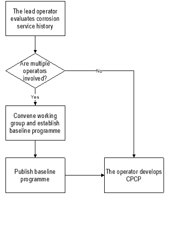
Figure A4-3: Operator-developed baseline CPCP
(b) Individual operator-developed CPCP
An operator may develop their CPCP without reference to a baseline CPCP only when a baseline CPCP does not exist. The CPCP should be consistent with the requirements of the applicable operating rules. Any operator who develops their own CPCP without a baseline CPCP, should review all available corrosion-related service data on the individual aircraft model and similar design details in similar aircraft models when the operator’s data and the service difficulty report data show no entries.
3.1.4. Continuous analysis and surveillance
The operator’s continuous analysis and surveillance system should contain procedures to review corrosion inspection task findings and establish corrosion levels. These procedures should provide criteria for determining if findings that exceed allowable limits are an isolated incident not typical of the operator’s fleet. The operator’s programme should also provide for notifying the competent authority whenever a determination of Level 2 or Level 3 corrosion is made. Due to the potential urgent airworthiness concern associated with a Level 3 finding, the operator’s procedures should provide for notification as soon as possible but no later than 3 calendar days after the Level 3 determination has been made.
3.2. Baseline CPCP documentation
The baseline CPCP documentation should include instructions to implement the baseline CPCP. It may be in a printed form or other form acceptable to the competent authority. It should also be in a form that is easy to revise. The date of the last revision should be entered on each page. The baseline CPCP documentation should be clearly identified as a baseline CPCP. The aircraft make, model and the person who prepared the documentation should also be identified.
3.2.1. Purpose and background
This section of the documentation should state the purpose of the baseline CPCP, which is to establish minimum requirements for preventing and controlling corrosion that may jeopardise continuing airworthiness of the aircraft model fleet. The section should further state that an operator should include an effective CPCP in their maintenance or inspection programme.
3.2.2. Introduction
The introduction should include a general statement that corrosion becomes more widespread as aircraft age and that it is more likely to occur in conjunction with other damage such as fatigue cracking. The introduction should also indicate that it is not the intent of a CPCP to establish rigid requirements to eliminate all corrosion in the fleet, but to control corrosion at or below levels that do not jeopardise continued airworthiness. However, due to the unpredictability of corrosion, it must be removed and the structure repaired and corrosion prevention treatment reapplied.
3.2.3. Programme application
For a programme to be fully effective, it is essential that a corrosion inspection task be applied to all areas where corrosion may affect primary structure. This section should recommend that priority for implementing the CPCP be given to older aeroplanes and to areas requiring significant changes to previous maintenance procedures in order to meet corrosion prevention and control requirements. This section should allow an operator to continue its current corrosion control procedures in a given task area or zone where there is documentation to show that corrosion is being consistently controlled to Level 1.
3.2.4. Baseline CPCP
This section should fully describe the baseline CPCP. It should include the basic task, corrosion inspection task areas, implementation thresholds, and repeat intervals.
3.2.5. Reporting system
Procedures to report findings of Level 2 and Level 3 corrosion as necessary to the TCH and the competent authority should be clearly established in this section. The TCH should indicate any specific requirement they have for reporting on corrosion levels that may be needed to revise the baseline CPCP. The information on Level 2 corrosion may be needed in a form acceptable to the competent authority responsible for approval of any revision to the maintenance programme resulting from a Level 2 finding. The timing of reporting should take into account the processes for the periodic review (see 3.2.6). All Level 2 and Level 3 findings should be reported in accordance with any applicable AD, operator’s service difficulty reporting procedures or reporting required by other competent authorities. Procedures for alerting the competent authority of Level 3 findings should be established that expedite such reporting. This report to the competent authority shall be made after the determination of the corrosion level.
3.2.6 Periodic review
This section should establish a period for the TCH (or lead operator) and participating operators to meet with EASA and review the reported Level 2 and Level 3 findings. The purpose of this review is to assess the baseline CPCP and make adjustments if necessary. This may be accomplished through maintenance programme reviews conducted via the Maintenance Programme Industry Steering Committees (MRB Structures Working Group or equivalent meetings) for the model.
3.2.7. Corrosion-related airworthiness directives
This section should include a list of all ADs that contain requirements related to known corrosion-related problems. This section should state that these ADs are in addition to and take precedence over the operator’s CPCP.
3.2.8. Development of the baseline CPCP
This section should identify the actions taken in preparing the baseline CPCP. It should include a description of the participants, the documents (e.g. SBs, service letters, ADs, service difficulty reports, accident and incident reports) reviewed, and the methodology for selecting and categorising the corrosion-prone areas to be included in the baseline CPCP. The selection criteria for corrosion-prone areas should be based on areas having similar corrosion exposure characteristics and inspection access requirements. Some corrosion-prone areas that should be considered are the main wing box, the fuselage crown, the bilge, areas under lavatories and galleys, etc. This section should state that the implementation threshold was selected to represent the typical aircraft age beyond which an effective corrosion inspection task should be implemented for a given task area.
3.2.9. Procedures for recording corrosion inspection findings
EASA has not imposed a requirement for additional record-keeping for an operator’s CPCP. However, the operator should maintain adequate records to substantiate any proposed programme adjustments. For example, an operator should maintain records to enable the operator to determine the amount of damage that has occurred during the repeat interval for each corrosion inspection task. Such data should be maintained for multiple repeat intervals in order to determine whether the damage remains constant or is increasing or decreasing. Such records are necessary when an operator is seeking approval for interval extension (escalation) or task reduction.
3.2.10. Glossary
This section should define all terms specifically used in the baseline CPCP documentation.
3.2.11. Application of the basic task
This section should describe in detail the basic task. It should provide procedures describing how to accomplish the following actions:
(a) Removal of all systems equipment and interior furnishings to allow access to the area.
(b) Cleaning of the area as required.
(c) Visual inspection of all task areas and zones listed in the baseline CPCP.
(d) Removal of all corrosion, damage evaluation, and repair of structure as necessary.
(e) Unblocking holes and gaps that may hinder drainage.
(f) Application of corrosion protective compounds.
(g) Reinstallation of dry insulation blankets, if applicable.
3.2.12. Determination of corrosion levels based on findings
This section should describe how the corrosion level definitions are used in evaluating the corrosion findings and assigning a corrosion level. This section should also instruct the operator to consult the DAH or the competent authority for advice in determining corrosion levels.
3.2.13. Typical actions following determination of corrosion levels
This section should establish criteria for evaluating whether or not Level 2 or Level 3 corrosion is occurring on other aircraft in the operator’s fleet. Criteria to be considered include: cause of the corrosion problem, past maintenance history, operating environment, production build standard, years in service, and inspectability of the corroded area. These and any other identified criteria should be used in identifying those aircraft that should be included in a fleet campaign. The results of the fleet campaign should be used to determine necessary adjustments in the operator’s CPCP. The following instructions should also be included in this section:
(a) If corrosion exceeding the allowable limit is found during accomplishment of the corrosion inspection task implementation threshold for a task area, it may be necessary to adjust the CPCP. (See ‘NOTE’ under ‘Level 2 corrosion’ definition)
(b) A single isolated occurrence of corrosion between successive inspections that exceeds Level 1 does not necessarily warrant a change in the operator’s CPCP. If the operator experiences multiple occurrences of Level 2 or Level 3 corrosion for a specific task area, then the operator should implement a change to the CPCP.
(c) The operator should not defer maintenance actions for Level 2 and Level 3 corrosion. These maintenance actions should be accomplished in accordance with the operator’s maintenance manual.
(d) The operator may implement changes such as the following to improve the effectiveness of the programme:
(1) reduction of the repeat interval,
(2) multiple applications of corrosion treatments,
(3) additional drainage provisions,
(4) incorporation of DAHs service information, such as SBs and service letters.
3.2.14. Programme implementation
This section should state that each task is to be implemented on each aircraft when the aircraft reaches the age represented by the implementation threshold for the task. It should also describe procedures to be used for establishing a schedule for implementation where the aircraft age exceeds the implementation threshold for individual tasks. Finally, it should state that once a task is implemented in an area, subsequent tasks are to be accomplished at the repeat interval in that task area.
4. DEVELOPMENT OF OPERATORS PROGRAMME
4.1. Baseline CPCP available
If a baseline CPCP is available, the operator should use it as a basis for developing their CPCP. In addition to adopting the basic task, task areas, implementation thresholds and repeat intervals of the baseline CPCP, the operator should make provisions for:
(a) aeroplanes that have exceeded the implementation threshold for certain tasks,
(b) aeroplanes being removed from storage,
(c) unanticipated scheduling adjustments,
(d) corrosion findings made during non-CPCP inspections,
(e) adding newly acquired aircraft, and
(f) modifications, configuration changes, and operating environment.
4.1.1. Provisions for aircraft that have exceeded the implementation threshold
The operator’s CPCP must establish a schedule for accomplishing all corrosion inspection tasks in task areas where the aircraft age has exceeded the implementation threshold (see main text of AMC paragraph 12).
4.1.2. Aeroplanes being removed from storage
Corrosion inspection task intervals are established based on elapsed calendar time. Elapsed calendar time includes time out of service. The operator’s CPCP should provide procedures for establishing a schedule for accomplishment of corrosion inspection tasks that have accrued during the storage period.
The schedule should result in accomplishment of all accrued corrosion inspection tasks before the aircraft is placed in service.
4.1.3. Unanticipated scheduling adjustments
The operator’s CPCP should include provisions for adjustment of the repeat interval for unanticipated schedule changes. Such provisions should not exceed 10 % of the repeat interval. The CPCP should include provisions for notifying the competent authority when an unanticipated scheduling adjustment is made.
4.1.4. Corrosion findings made during non-CPCP inspections
Corrosion findings that exceed allowable limits may be found during any scheduled or unscheduled maintenance or inspection activities. These findings may be indicative of an ineffective CPCP. The operator should make provision in their CPCP to evaluate these findings and adjust their CPCP accordingly.
4.1.5. Adding newly acquired aircraft
Before adding any aircraft to the fleet, the operator should establish a schedule for accomplishing all corrosion inspection tasks in all task areas that are due. This schedule should be established as follows:
(a) For aircraft that have previously operated under an approved maintenance programme, the initial corrosion inspection task for the new operator must be accomplished in accordance with the previous operator’s schedule or in accordance with the new operator’s schedule, whichever would result in the earliest accomplishment of the corrosion inspection task.
(b) For aircraft that have not previously been operated under an approved maintenance programme, each initial corrosion task inspection must be accomplished either before the aircraft is added to the operator’s fleet, or in accordance with the schedule approved by the competent authority. After each corrosion inspection task has been performed once, the subsequent corrosion task inspections should be accomplished in accordance with the new operator’s schedule.
4.1.6. Modifications, configuration changes and operating environment
The operator must ensure that their CPCP takes account of any modifications, configurations changes and the operating environment applicable to them, that were not addressed in the baseline CPCP documentation.
4.2. Baseline CPCP not available
If there is no baseline CPCP available for the operator to use in developing their CPCP, the operator should develop their CPCP using the provisions listed in Paragraph 3 of this Appendix for a baseline CPCP as well as the provisions listed in subparagraphs 4.1.1 through 4.1.6 of this paragraph.
[Amdt 20/2]
[Amdt 20/20]
Appendix 5 to AMC 20-20A Guidelines for ensuring the validity of continuing structural integrity programmes
ED Decision 2020/023/R
1. GENERAL
Point 26.305 of Part-26 requires a process that ensures that the continuing structural integrity programme remains valid throughout the operational life of the aircraft, considering service experience and current operations. The intent is for the TCHs of large transport aeroplanes to review the validity of the certification assumptions upon which the maintenance programme is based and to ensure that unsafe levels of fatigue cracking or other damage will be minimised in service. This Appendix provides guidance as to what the processes should include.
This Appendix also provides interpretation, guidelines and EASA accepted means of compliance for the review of structural SBs including a procedure for selection, assessment and related recommended corrective action for ageing aircraft structures.
2. CONTENT OF PROCESSES FOR COMPLIANCE WITH POINT 26.305 of PART-26
CS 26.305 establishes compliance on the basis of sub-paragraphs (a) to (g), reproduced below, and consideration of the criteria of sub-paragraph (h):
(a) a process exists, and a report that describes the process and how it is implemented is submitted to EASA; and
(b) the process is either continuous with each service finding or is a regular review following a number of findings, or a combination of both; and
(c) the process includes a plan to audit and report to EASA the effectiveness of the continuing structural integrity programme, including the continuing validity of the assumptions upon which it is based, prior to reaching any significant point in the life of the aircraft; and
(d) the process includes criteria for summarising findings of fatigue environmental or accidental damage and their causes and recording them in a way that allows any potential interaction to be evaluated; and
(e) the process includes criteria to assess and record the relevance of each potential contributing factor to the finding, including operational usage, fatigue load spectra, environmental conditions, material properties, manufacturing processes and the fatigue and damage tolerance analysis methodology and its implementation; and
(f) the process includes criteria for establishing and revising sampling programmes to supplement the inspections and other procedures established in compliance with the applicable fatigue and damage tolerance requirements; and
(g) the process includes criteria for establishing when structure should be modified or the inspection programme revised in the light of in-service damage findings.
(h) Sunset criteria: The extent to which the above elements of the process require definition may be tailored to the size of the fleet and its expected useful remaining life (e.g. if less than 10 % of the fleet remains in operation worldwide at the date of applicability of point 26.305 and there is significant experience of aircraft reaching the maximum expected operating life, then additional criteria beyond the existing processes may be agreed to be unnecessary).
It should be noted that point 26.305 of Part-26 applies to all structure whose failure could contribute to a catastrophic failure, and is not limited to metallic structures and fatigue cracking, but should also encompass composite and hybrid structures.
The reporting of findings that could be relevant to the continuing structural integrity of the aeroplane should be facilitated by providing clear instructions and easy-to-use reporting means to operators that encourage and facilitate both their support and that of the customer support staff in identifying developing risks.
The intent of the audit and the associated report is to provide the TCH and EASA with a series of properly planned opportunities to assess the continuing structural integrity programme for significant systemic shortcomings and take timely action in advance of potential unsafe conditions. The audit should consider each of the parts of the continuing structural integrity programme and any links between them or with programmes for other types. In the context of this requirement, the audit should address all structures, not only metallic structures.
The audit report should summarise the processes and their evolutions. The report should describe any measures taken in the audit that are beyond the basic processes described in the original summary report in compliance with point 26.305 of Part-26 (e.g. additional field inspections or tear down inspections of fleet leading aircraft in terms of age and usage). The report should summarise the status of each part of the continuing structural integrity programme, the findings of the audit and proposals for the actions to be taken.
The audit should provide evidence that the processes required by point 26.305 of Part-26 have been properly implemented, such that:
— reported service findings have been recorded and summarised in a way that allows causes, trends and actions to be reviewed;
— service findings are evaluated for consistency with the assumptions on which the programme is based;
— the continuing structural integrity programme remains effective (e.g. changes have been made to the programme in response to findings, and few emergency or short-term airworthiness actions have been necessary);
— a comparison of the loading, operational usage, fatigue methodology, design tools, and test evidence with that upon which the programme is based, shows that the programme remains valid;
— causal analysis results have been reviewed and evaluated for evidence of repetitive themes for which no specific action has been taken; and
— the fleet leader sampling programme has been implemented, and any findings resulting from it have been properly dispositioned.
The audit report should record how any deviations from the applicable processes, identified during the audit, have been or will be addressed.
Significant points in the aircraft life that should be considered in the audit plan include: points at which a common threshold exist for multiple damage-tolerance-based inspections, half-DSG, DSG, LOV, etc. In order to plan for a timely assessment that will allow proactive revision of the maintenance programme, the audit should take place several years before reaching the significant point.
Assumptions made at certification and subsequently regarding key operating variable parameters such as weight, fuel, payload, mission length, etc., should be evaluated on a regular basis or each time a finding indicates that the assumptions may be compromised, resulting in an adverse effect on the fatigue analysis and inspection programme.
One way to ensure confidence in the maintenance programme is by establishing a fleet leader sampling programme encompassing various operators and operations in different environments. This may, for example, be developed in coordination with the MRB and requires the cooperation of the leading operators. The sampling programme need not address all potential damage locations, and should focus on the most critical that would provide early indications of potentially erroneous assumptions. Sampling may also be beneficial where new materials or methods of construction have been introduced, especially when the extent of testing may have been limited at certification, e.g. for areas of hybrid structure where the temperature differential was not part of the full-scale fatigue test. The sampling programme may also impose more intrusive or detailed inspections and analyses of samples taken from the structure (for composites or other materials subject to environmental degradation).
The details of the sampling programme requirements and the associated reporting requirements should be established in coordination with the operators. The ICA, in compliance with Appendix H to CS-25, may need to be supplemented with this information to support the core compliance elements of the continuing structural integrity programme generated through compliance with CS 25.571.
The process for establishing when a structure should be modified or the inspection programme revised in the light of in-service damage findings should include special consideration of:
— damage detected and reported before the inspection threshold; and
— damage that is generally being found at or near to the critical crack size; and
— changing damage configurations for which the reasons are not fully understood; and
— new damage scenarios reported under existing inspection or repair procedures that could otherwise be considered to be addressed, and overlooked.
The objectives of modifying structures are to provide a reasonably high probability that the ultimate load capability will be retained over long periods of the aircraft’s life, and to significantly reduce the potential for interaction with new cracking that may develop later in the aircraft’s life.
The following guidance regarding the SB review process is retained from the original issue of this AMC for general guidance on the subject, and the criteria for bulletin selection provide useful additional factors for establishing when structures should be modified or the inspection programme revised.
3. SB REVIEW PROCESS
SBs issued early in the life of an aircraft fleet may utilise inspections (in some cases non‑mandatory inspections) alone to maintain structural integrity. Inspections may be adequate at this early stage, when cracking is possible, but not highly likely. However, as aircraft age, the probability of fatigue cracking becomes more likely. During this later period, it is not prudent to rely only on inspections alone because there are more opportunities for cracks to be missed, and cracks may no longer occur in isolation. It is then prudent to reduce reliance strictly on inspections, with their inherent human factors limitations, and to incorporate modifications to the structure to eliminate the source of the cracking. In some cases, reliance on an inspection programme, in lieu of modification, may be acceptable through the increased use of mandatory versus non-mandatory inspections.
The TCH, in conjunction with the operators, is expected to initiate a review of all structurally related inspection and modification SBs and determine which require further actions to ensure continued airworthiness, including mandatory modification action or enforcement of special repetitive inspections.
Any aircraft primary structural components that would require frequent repeat inspections, or where the inspection is difficult to perform, taking into account the potential airworthiness concern, should be reviewed to preclude the human factors issues associated with repetitive inspections.
The SB review is an iterative process consisting of the following items:
(a) The TCH or the TCH in conjunction with the operators at a preliminary STG meeting should review all the issued structural inspection and modification SBs to select candidate bulletins, using the following four criteria:
(i) There is a high probability that structural cracking exists.
Related to the number and type of finding in service and from fatigue testing.
A ‘no finding’ result should be associated with the number of performed inspections.
The type of finding should include an analysis of its criticality.
(ii) Potential structural airworthiness concern
The structural airworthiness of the aircraft is dependent on repeat inspections to verify its structural condition, and therefore on the reliability of the inspections.
A short repeat inspection interval (e.g. a short time for a crack to grow from a detectable crack to a critical length divided by a factor) will lead to increased workloads for inspectors and a possible increased risk of them missing damage.
Special attention should be paid to any single inspection tasks involving multiple repeat actions needed to verify the structural condition that may increase the risk of the inspectors missing damage (e.g. lap splice inspections).
(iii) Damage is difficult to detect during routine maintenance (i.e. there are few additional opportunities for detection beyond the specific requirement of the SB). (Of particular concern is damage that is found when it is well-developed and closer to being critical, rather than damage which is in the early stages with several further opportunities available for detection before it becomes critical.)
The areas to be inspected are difficult to access.
NDI methods are proving unsuitable.
The human factors associated with the inspection technique are so adverse that the detection of cracks may not be sufficiently dependable to assure safety.
(iv) There is adjacent structural damage or the potential for it.
Particular attention should be paid to areas susceptible to WFD and also to potential interaction between corrosion and fatigue cracking, e.g. between fastener damage (due to stress corrosion or other factors) and fatigue cracking.
It is recommended to consider the potential interaction of modifications or repairs usually implemented in the areas concerned to check whether the inspections are still reliable or not (operator’s input).
(b) The TCH and operator members will be requested to submit information on their individual fleet experience related to candidate SBs. This information will be collected and evaluated by the TCH. The summarised results will then be reviewed in detail at an STG meeting (see point (c) below).
(c) The final selection of SBs for recommendation of the appropriate corrective action to assure structural continued airworthiness, taking into account the in-service experience, will be made during an STG meeting by the voting members of the STG, either by consensus or majority vote, depending on the preference of the individual STGs.
(d) An assessment will be made by the TCH as to whether or not any subsequent revisions to SBs affect the decisions previously made. Any subsequent revisions to the SBs previously chosen by the STG for mandatory inspection or incorporation of modification action that would affect the previous STG recommended action should be submitted to the STG for review.
(e) The TCH should review all new structural SBs periodically to select further candidate bulletins. The TCH should schedule a meeting of the STG to address the candidates. Operator members and the competent authority will be advised of the selected candidates and provided with the opportunity to submit additional candidates.
The SB selection, review, assessment and recommendation process within the Structural Task Group (STG) is summarised in Figure A5-1. For the first SB review within an STG meeting, all the inspection SBs should be selected. Moreover, some specific modification SBs not linked to an inspection SB may also be selected for review.
The information input by operators should address the points as detailed in Figure A5-2. This information should be collected and analysed by the TCH for the STG meeting.
If, for a given selected SB, there is not sufficient in-service data available before the STG meeting that would enable a recommendation to be made, its review may be deferred until enough data is available. The TCH should then check periodically until the data becomes available.
The operators and EASA should be advised by the TCH of the SB selection list and be given the opportunity to submit additional SBs. For this purpose, the TCH should give the operators enough information in advance (e.g. 2 months) for them to be able to properly consider the proposed selection and to gather data.
When an SB is selected, it is recommended to also select, in the same package, inspection SBs that interact with it and all the related modification SBs. The main criteria for selecting SBs are defined in the following subparagraphs.
4. STG MEETING, SB REVIEW AND RECOMMENDATIONS
It is recommended to review at the same time all SBs that can interact, the so-called SB package, in the selection process. The meeting should start with an STG agreement on the selected SB list and on those deferred. At the meeting the TCH should present their analysis of each SB utilising the collection of operator input data. The STG should then collectively review the ratings (Figure A5-2) against each criterion to reach a consensus recommendation. Such an STG recommendation for a selected SB shall consider the following options:
(a) to mandate a structural modification at a given threshold,
(b) to mandate the selected inspection SB,
(c) to revise the modification or repair actions,
(d) to revise other SB(s) in the same area concerned by damages,
(e) to review the inspection method and related inspection intervals,
(f) to review ALI/MRBR or other maintenance instructions,
(g) to defer the review to the next STG and request operators’ reports on findings for a specific SB or request an inspection sampling on the oldest aircraft.
STG recommendations for mandatory action are the responsibility of the TCH to forward to EASA for appropriate action. Other STG recommendations is information provided to the STG members. It is their own responsibility to carry them out within the appropriate framework.
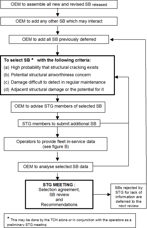
Figure A5-1: SB selection process and SB review
IN-SERVICE DATA/SECTION 1
|
NAME OF THE OPERATOR: |
|
AIRCRAFT MODEL/SERIES: |
|
|
|
SERVICE BULLETIN (SB) NUMBER: |
|
|
|
TITLE:____________________________________________________________________________________ |
|
|
|
RELATED INSPECTION/MODIFICATION SB: |
|
1/_______________________________________________________________________________________ |
|
|
|
2/_______________________________________________________________________________________ |
|
|
|
3/_______________________________________________________________________________________ |
|
|
|
SB MANDATED? YES NO |
|
IF NOT, IS THE SB IMPLEMENTED IN THE MAINTENANCE PROGRAMME? YES NO |
|
|
|
|
|
NUMBER OF AIRCRAFT TO WHICH THE SB APPLIES (INCLUDING ALL AIRCRAFT IN THE SB EFFECTIVITY): |
|
|
|
NUMBER OF AIRCRAFT EXCEEDING THE SB INSPECTION THRESHOLD (IF APPLICABLE): |
|
|
|
NUMBER OF AIRCRAFT INSPECTED PER SB (IF APPLICABLE)? |
|
|
|
SPECIFY TYPE OF INSPECTION USED: _________________________________________________________________________________________ |
|
|
|
NUMBER OF AIRCRAFT WITH REPORTED FINDINGS: |
TYPE OF FINDINGS:
|
NUMBER OF FINDINGS DUE TO INSPECTIONS OTHER THAN THE ONE PRESCRIBED IN THE SB (IF APPLICABLE): |
|
SPECIFY TYPE OF INSPECTION USED: |
|
|
|
NUMBER OF AIRCRAFT EXCEEDING THE SB TERMINATING MODIFICATION THRESHOLD (IF APPLICABLE): |
|
NUMBER OF AIRCRAFT IN WHICH THE TERMINATING MODIFICATION HAS BEEN ACCOMPLISHED (IF APPLICABLE): |
|
|
|
NEED THIS SB (OR RELATED SB) BE IMPROVED? YES NO |
|
|
|
COMMENTS: ______________________________________________________________________________ |
|
_________________________________________________________________________________________ |
IN-SERVICE DATA/SECTION 2
|
|
(A) |
(B) |
(C) |
(D) |
(E) |
|
CRITERIA |
INSPECTABILITY ACCESS |
FREQUENCY REPETITIVE INSPECTION |
FREQUENCY OF DEFECTS |
SEVERITY RATING |
ADJACENT STRUCTURE DAMAGE |
|
RATING |
|
|
|
|
|
FIGURE A5-2: Operators fleet experience
(A) INSPECTABILITY/ACCESS RATING
OK Inspection carried out with little or no difficulty.
Acceptable Inspection carried out with some difficulty.
Difficulty Inspection carried out with significant difficulty.
Note: Rating should consider difficulty of access as well as inspection technique and size of inspection area.
(B) FREQUENCY OF REPETITIVE INSPECTIONS RATING
OK Greater than 6 years.
Acceptable Between 2 and 6 years.
Difficulty Less than 2 years.
(C) FREQUENCY OF DEFECTS NOTED RATING = % OF THOSE AEROPLANES BEYOND THRESHOLD ON WHICH DEFECTS HAVE BEEN FOUND
OK No defect noted.
Acceptable Defects noted but not of a significant amount (less than 10 %).
Difficulty Substantial defects noted (greater than 10 %).
(D) FINDING SEVERITY RATING
OK Airworthiness not affected.
Acceptable Damage not of immediate concern, but could progress or cause secondary damage.
Difficulty Airworthiness affected. Damage requires immediate repair.
(E) ADJACENT STRUCTURE DAMAGE RATING (MULTIPLE-SITE DAMAGE, MULTIPLE-ELEMENT DAMAGE, CORROSION, ETC.)
OK Low rate of adjacent structural damage.
Acceptable Medium rate of adjacent structural damage.
Difficulty High rate of adjacent structural damage/Multiple service actions in area.
[Amdt 20/2]
[Amdt 20/20]