ED Decision 2003/15/RM
(a) The rotorcraft, although it may be damaged in emergency landing conditions on land or water, must be designed as prescribed in this paragraph to protect the occupants under those conditions.
(b) The structure must be designed to give each occupant every reasonable chance of escaping serious injury in a crash landing when:
(1) Proper use is made of seats, belts, and other safety design provisions;
(2) The wheels are retracted (where applicable) ; and
(3) Each occupant and each item of mass inside the cabin that could injure an occupant is restrained when subjected to the following ultimate inertial load factors relative to the surrounding structure:
(i) Upward – 4 g
(ii) Forward – 16 g
(iii) Sideward – 8 g
(iv) Downward – 20 g, after the intended displacement of the seat device
(v) Rearward – 1.5 g
(c) The supporting structure must be designed to restrain, under any ultimate inertial load up to those specified in this paragraph, any item of mass above and/or behind the crew and passenger compartment that could injure an occupant if it came loose in an emergency landing. Items of mass to be considered include, but are not limited to, rotors, transmissions, and engines. The items of mass must be restrained for the following ultimate inertial load factors:
(1) Upward – 1.5 g
(2) Forward – 12 g
(3) Sideward – 6 g
(4) Downward – 12 g
(5) Rearward – 1.5 g
(d) Any fuselage structure in the area of internal fuel tanks below the passenger floor level must be designed to resist the following ultimate inertial factors and loads and to protect the fuel tanks from rupture when those loads are applied to that area:
(1) Upward – 1.5 g
(2) Forward – 4.0 g
(3) Sideward – 2.0 g
(4) Downward – 4.0 g
CS 27.562 Emergency landing dynamic conditions
ED Decision 2003/15/RM
(a) The rotorcraft, although it may be damaged in an emergency crash landing, must be designed to reasonably protect each occupant when:
(1) The occupant properly uses the seats, safety belts, and shoulder harnesses provided in the design; and
(2) The occupant is exposed to the loads resulting from the conditions prescribed in this paragraph.
(b) Each seat type design or other seating device approved for crew or passenger occupancy during take-off and landing must successfully complete dynamic tests or be demonstrated by rational analysis based on dynamic tests of a similar type seat in accordance with the following criteria. The tests must be conducted with an occupant, simulated by a 77 kg (170-pound) anthropomorphic test dummy (ATD), sitting in the normal upright position.
(1) A change in downward velocity of not less than 9.1 m/s (30 ft/s) when the seat or other seating device is oriented in its nominal position with respect to the rotorcraft’s reference system, the rotorcraft’s longitudinal axis is canted upward 60° with respect to the impact velocity vector, and the rotorcraft’s lateral axis is perpendicular to a vertical plane containing the impact velocity vector and the rotorcraft’s longitudinal axis. Peak floor deceleration must occur in not more than 0.031 seconds after impact and must reach a minimum of 30 g.
(2) A change in forward velocity of not less than 12.8 m/s (42 ft/s) when the seat or other seating device is oriented in its nominal position with respect to the rotorcraft’s reference system, the rotorcraft’s longitudinal axis is yawed 10° either right or left of the impact velocity vector (whichever would cause the greatest load on the shoulder harness), the rotorcraft’s lateral axis is contained in a horizontal plane containing the impact velocity vector, and the rotorcraft’s vertical axis is perpendicular to a horizontal plane containing the impact velocity vector. Peak floor deceleration must occur in not more than 0.071 seconds after impact and must reach a minimum of 18.4 g.
(3) Where floor rails or floor or sidewall attachment devices are used to attach the seating devices to the airframe structure for the conditions of this paragraph, the rails or devices must be misaligned with respect to each other by at least 10° vertically (i.e. pitch out of parallel) and by at least a 10° lateral roll, with the directions optional, to account for possible floor warp.
(c) Compliance with the following must be shown:
(1) The seating device system must remain intact although it may experience separation intended as part of its design.
(2) The attachment between the seating device and the airframe structure must remain intact, although the structure may have exceeded its limit load.
(3) The ATD’s shoulder harness strap or straps must remain on or in the immediate vicinity of the ATD’s shoulder during the impact.
(4) The safety belt must remain on the ATD’s pelvis during the impact.
(5) The ATD’s head either does not contact any portion of the crew or passenger compartment, or if contact is made, the head impact does not exceed a head injury criteria (HIC) of 1000 as determined by this equation.
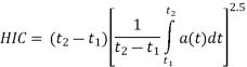
Where: a(t) is the resultant acceleration at the centre of gravity of the head form expressed as a multiple of g (the acceleration of gravity) and t2-t1 is the time duration, in seconds, of major head impact, not to exceed 0.05 seconds.
(6) Loads in individual upper torso harness straps must not exceed 7784 N (1750 lbs). If dual straps are used for retaining the upper torso, the total harness strap loads must not exceed 8896 N (2000 lbs).
(7) The maximum compressive load measured between the pelvis and the lumbar column of the ATD must not exceed 6674 N (1500 lbs).
(d) An alternate approach that achieves an equivalent or greater level of occupant protection, as required by this paragraph, must be substantiated on a rational basis.
CS 27.563 Structural ditching and emergency flotation provisions
ED Decision 2018/007/R
If certification with ditching provisions or if certification with emergency flotation provisions is requested by the applicant, structural strength must meet the requirements of this CS. If certification with ditching provisions is requested by the applicant, the requirements of CS 27.801(f) must also be met. The loading conditions apply to all parts of the rotorcraft, unless otherwise stated by this CS and CS 27.802(b).
(a) Landing conditions. The conditions considered must be those resulting from an emergency landing into the most severe sea conditions for which certification is requested by the applicant, at a forward ground speed not less than 15.4 m/s (30 knots), and a vertical speed not less than 1.5 m/s (5 ft/s), in likely pitch, roll and yaw attitudes. Rotor lift may be assumed to act through the centre of gravity during water entry. This lift may not exceed two-thirds of the design maximum weight.
(b) Loads.
(1) Floats fixed or intended to be deployed before initial water contact. The loads to be considered are those resulting from the rotorcraft entering the water, in the conditions defined in (a), and in accordance with flight manual procedures. In addition, each float, and its support and attaching structure, must be designed for the loads developed by a fully immersed float unless it can be shown that full immersion is unlikely. If full immersion is unlikely, the highest likely float buoyancy load must be applied. Appropriate air loads shall be used in substantiation of the floats and their attachment to the rotorcraft. For this purpose, the design airspeed for limit load is the maximum operating airspeed limit with fixed or deployed floats multiplied by 1.11.
In the case of approval with ditching provisions, water entry with deployable floats in the unintended stowed position must also be accounted for. It must be established that in such a case, damage to the un-deployed floats, attachments or surrounding structure, that would prevent proper deployment and functioning of the floats, will not occur.
(2) Floats intended to be deployed after initial water contact. The loads to be considered are those resulting from the rotorcraft entering the water, in the conditions defined in (a), and in accordance with flight manual procedures. In addition, each float and its support and attaching structure must be designed for combined vertical and drag loads. The vertical load must be that developed by a fully immersed float, unless it can be shown that full immersion is unlikely. If full immersion is unlikely, the highest likely float buoyancy load must be applied. The drag load must be determined assuming a relative speed of 10.3 m/s (20 knots) between the rotorcraft and the water.
[Amdt No: 27/5]
AMC 27.563 Structural ditching and emergency flotation provisions
ED Decision 2018/007/R
This AMC replaces FAA AC 27.563 and AC 27.563A.
(a) Explanation.
This AMC contains specific structural conditions to be considered to support the ditching requirements of CS 27.801, and the emergency flotation requirements of CS 27.802.
For rotorcraft for which certification with ditching provisions is requested by the applicant, in accordance with CS 27.801(a), the structural conditions apply to the complete rotorcraft.
For rotorcraft for which certification with emergency flotation provisions is requested by the applicant, in accordance with CS 27.802(b), the structural conditions apply only to the flotation units and their attachments to the rotorcraft.
At Amendment 5, the requirement for flotation stability on waves was appreciably changed. A requirement for the substantiation of acceptable stability by means of scale model testing in irregular waves was introduced at this amendment. This change made the usage of Sea State (World Meteorological Organization) no longer appropriate. The sea conditions are now defined in terms of significant wave height (Hs) and mean wave period (Tz). These terms are therefore also used in this AMC when defining sea conditions.
(1) The landing conditions specified in CS 27.563(a) may be considered as follows:
(i) The rotorcraft contacts the most severe sea conditions for which certification with ditching or emergency flotation provisions is requested by the applicant, selected in accordance with Table 1 of AMC to CS 27.801(e) and 27.802(c) and as illustrated in Figure 1a). These conditions may be simulated considering the rotorcraft contacting a plane of stationary water as illustrated in Figure 1b), inclined with a range of steepness from zero to the significant steepness given by Ss=2πHs/(gTz2). Values of Ss are given in Table 1 of AMC to 27.801(e) and 27.802(c). The rotorcraft contacts the inclined plane of stationary water with a flight direction contained in a vertical plane. This vertical plane is perpendicular to the inclined plane, as illustrated in Figure 1 b). Likely rotorcraft pitch, roll and yaw attitudes at water entry that would reasonably be expected to occur in service, should also be considered. Autorotation, run-on landing, or one-engine-inoperative flight tests, or a validated simulation should be used to confirm the attitudes selected.
(ii) The forward ground speed should not be less than 15.4 m/s (30 kt), and the vertical speed not less than 1.5 m/s (5 ft/s).
(iii) A rotor lift of not more than two-thirds of the design maximum weight may be assumed to act through the rotorcraft’s centre of gravity during water entry.
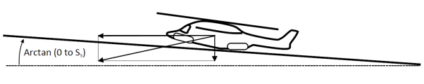
(iv) The above conditions may be simulated or tested using a calm horizontal water surface with an equivalent impact angle and speed relative to the water surface as illustrated in Figure 1 c).
(2) For floats that are fixed or intended to be deployed before water contact, CS 27.563(b)(1) defines the applicable load condition for entry into water, with the floats in their intended configuration.
CS 27.563(b)(1) also requires consideration of the following cases:
— The floats and their attachments to the rotorcraft should be designed for the loads resulting from a fully immersed float unless it is shown that full immersion is unlikely. If full immersion is shown to be unlikely, the determination of the highest likely buoyancy load should include consideration of a partially immersed float creating restoring moments to compensate for the upsetting moments caused by the side wind, unsymmetrical rotorcraft loading, water wave action, rotorcraft inertia, and probable structural damage and leakage considered under CS 27.801(e) or 27.802(c). The maximum roll and pitch angles established during compliance with CS 27.801(e) or 27.802(c) may be used, to determine the extent of immersion of each float. When determining this, damage to the rotorcraft that could be reasonably expected should be accounted for.
— To mitigate the case when the crew is unable to, or omits to, deploy a normally stowed emergency flotation system before entering the water, if approval with ditching provisions is sought, it should be substantiated that the floats will survive and function properly. The floats in their un-deployed condition, their attachments to the rotorcraft and the local structure should be designed to withstand the water entry loads without damage that would prevent the floats inflating as intended. Risks such as the splintering of surrounding components in a way that might damage the un-deployed or deploying floats should be considered. There is, however, no requirement to assess the expected loading on other parts of the rotorcraft when entering the water, with unintended un-deployed floats.
— The floats and their attachments to the rotorcraft should be substantiated as capable of withstanding the loads generated in flight. The airspeed chosen for assessment of the loads should be the appropriate operating limitation multiplied by 1.11. For fixed floats, the operating limitation should be the rotorcraft VNE. For deployable floats, if an operating limitation for the deployment of floats and/or flight with floats deployed is given, the highest such limitation should be used, otherwise the rotorcraft VNE should be used.
(3) For floats intended to be deployed after water contact, CS 27.563(b)(2) requires the floats and their attachments to the rotorcraft to be designed to withstand the loads generated when entering the water with the floats in their intended condition.
Simultaneous vertical and drag loading on the floats and their attachments should be considered to account for the rotorcraft moving forward through the water during float deployment.
The vertical loads should be those resulting from fully immersed floats unless it is shown that full immersion is unlikely. If full immersion is shown to be unlikely, the determination of the highest likely buoyancy load should include consideration of a partially immersed float creating restoring moments to compensate for the upsetting moments caused by side wind, unsymmetrical rotorcraft loading, water wave action, rotorcraft inertia, and probable structural damage and leakage considered under CS 27.801(e) or 27.802(c). The maximum roll and pitch angles established during compliance with CS 27.801(e) or 27.802(c) may be used, if significant, to determine the extent of immersion of each float. When determining this, damage to the rotorcraft that could be reasonably expected should be accounted for.
The drag loads should be those resulting from movement of the rotorcraft through the water at 10.3 m/s (20 knots).
(b) Procedures
(1) The floats and the float attachment structure should be substantiated for rational limit and ultimate loads.
(2) The most severe sea conditions for which certification with ditching or emergency flotation provisions is requested by the applicant are to be considered. The sea conditions should be selected in accordance with the AMC to CS 27.801(e) and 27.802(c).
(3) Landing load factors and the water load distribution may be determined by water drop tests or validated analysis.
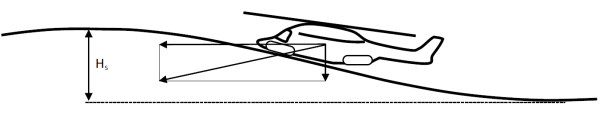
a) Water entry into wave
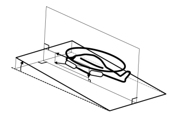
b) Water entry into inclined plane of stationary water, steepness range - zero to significant steepness (Ss)
![]()
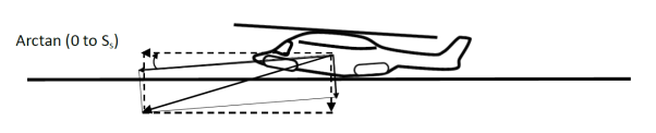
c) Water entry into a stationary horizontal water surface using an equivalent water entry angle and velocity relative to the water surface
(Dashed arrows show required horizontal and vertical speeds)
Figure 1 – Illustration of water entry test or simulation conditions which may be considered for structural provisions assessment
[Amdt No: 27/5]