ED Decision 2003/15/RM
(a) The flight load factor must be assumed to act normal to the longitudinal axis of the rotorcraft, and to be equal in magnitude and opposite in direction to the rotorcraft inertia load factor at the centre of gravity.
(b) Compliance with the flight load requirements of this Subpart must be shown:
(1) At each weight from the design minimum weight to the design maximum weight; and
(2) With any practical distribution of disposable load within the operating limitations in the Rotorcraft Flight Manual.
CS 27.337 Limit manoeuvring load factor
ED Decision 2003/15/RM
The rotorcraft must be designed for:
(a) A limit manoeuvring load factor ranging from a positive limit of 3.5 to a negative limit of – 1.0; or
(b) Any positive limit manoeuvring load factor not less than 2.0 and any negative limit manoeuvring load factor of not less than – 0.5 for which:
(1) The probability of being exceeded is shown by analysis and flight tests to be extremely remote; and
(2) The selected values are appropriate to each weight condition between the design maximum and design minimum weights.
AMC1 27.337 Limit manoeuvring load factor
ED Decision 2023/001/R
This AMC supplements FAA AC 27-1B, § AC 27.337 and should be used in conjunction with that AC when demonstrating compliance with CS 27.337 for determining the positive limit manoeuvring load factor.
In accordance with CS 27.337, the rotorcraft may be substantiated to a maximum positive load factor less than +3.5 (but not less than 2.0) provided that the probability of being exceeded is shown to be extremely remote. Whenever this option is selected, the maximum available rotor lift with both power on and power off rotor speed ranges throughout the entire operational density envelope should be considered.
AC 27-1B, § AC 27.337(b)(1) provides some guidance as to the necessary considerations when substantiating manoeuvre load factors less than the specified values. Further clarification should be provided in this paragraph to specify that the entire operational envelope should be considered when determining the maximum available rotor lift.
The guidance should be read as follows:
§ AC 27.337(b)(1) The applicant may elect to substantiate the rotorcraft for a design manoeuvring load factor less than +3.5 and more than -1.0. Whenever this option is used, an analytical study and flight demonstration are required. Maximum available rotor lift with both power on and power off throughout the entire operational density envelope should be considered when substantiating manoeuvre load factors less than the specified values.
[Amdt 27/10]
CS 27.339 Resultant limit manoeuvring loads
ED Decision 2003/15/RM
The loads resulting from the application of limit manoeuvring load factors are assumed to act at the centre of each rotor hub and at each auxiliary lifting surface, and to act in directions, and with distributions of load among the rotors and auxiliary lifting surfaces, so as to represent each critical manoeuvring condition, including power-on and power-off flight with the maximum design rotor tip speed ratio. The rotor tip speed ratio is the ratio of the rotorcraft flight velocity component in the plane of the rotor disc to the rotational tip speed of the rotor blades, and is expressed as follows:
![]()
where:
V = The airspeed along the flight path;
a = The angle between the projection, in the plane of symmetry, of the axis of no feathering and a line perpendicular to the flight path (positive when the axis is pointing aft);
Ω = The angular velocity of rotor; and
R = The rotor radius.
ED Decision 2003/15/RM
The rotorcraft must be designed to withstand, at each critical airspeed including hovering, the loads resulting from a vertical gust of 9.1 m/s (30 ft/s).
ED Decision 2003/15/RM
(a) Each rotorcaft must be designed for the loads resulting from the manoeuvres specified in sub-paragraphs (b) and (c) with:
(1) Unbalanced aerodynamic moments about the centre of gravity which the aircraft reacts to in a rational or conservative manner considering the principal masses furnishing the reacting inertia forces; and
(2) Maximum main rotor speed.
(b) To produce the load required in subparagraph (a), in unaccelerated flight with zero yaw, at forward speeds from zero up to 0.6 VNE:
(1) Displace the cockpit directional control suddenly to the maximum deflection limited by the control stops or by the maximum pilot force specified in CS 27.397(a);
(2) Attain a resulting sideslip angle or 90°, whichever is less; and
(3) Return the directional control suddenly to neutral.
(c) To produce the load required in sub-paragraph (a), in unaccelerated flight with zero yaw, at forward speeds from 0.6 VNE up to VNE or VH, whichever is less:
(1) Displace the cockpit directional control suddenly to the maximum deflection limited by the control stops or by the maximum pilot force specified in CS 27.397(a);
(2) Attain a resulting sideslip angle or 15°, whichever is less, at the lesser speed of VNE or VH;
(3) Vary the sideslip angles of subparagraphs (b)(2) and (c)(2) directly with speed; and
(4) Return the directional control suddenly to neutral.
AMC No 1 to CS 27.351 Yawing conditions
ED Decision 2016/024/R
(a) Definitions:
(1) Suddenly. For the purpose of this AMC, ‘suddenly’ is defined as an interval not to exceed 0.2 seconds for a complete control input. A rational analysis may be used to substantiate an alternative value.
(2) Initial Trim Condition. Steady, 1G level flight condition with zero bank angle or zero sideslip.
(3) ‘Line’. The rotorcraft’s sideslip envelope, defined by the rule, between 90° at 0.6VNE and 15° at VNE or VH whichever is less (see Figure 1).
(4) Resulting Sideslip Angle. The rotorcraft’s stabilised sideslip angle that results from a sustained maximum cockpit directional control deflection or as limited by pilot effort in the initial level flight power conditions.
(b) Explanation: The rule requires a rotorcraft’s ‘structural’ yaw or sideslip design envelope that must cover a minimum forward speed or hover to VNE or VH whichever is less. The scope of the rule is intended to cover structural components that are primarily designed for the critical combinations of tail rotor thrust, inertial and aerodynamic forces. This may include but is not limited to fuselage, tailboom and attachments, vertical control surfaces, tail rotor and tail rotor support structure.
(1) The rotorcraft’s structure must be designed to withstand the loads in the specified yawing conditions. The standard does not require a structural flight demonstration. It is a structural design standard.
(2) The standard applies only to power-on conditions. Autorotation need not be considered.
(3) This standard requires the maximum allowable rotor revolutions per minute (RPM) consistent with each flight condition for which certification is requested.
(4) For the purpose of this AMC, the analysis may be performed in international standard atmosphere (ISA) sea level conditions.
(5) Maximum displacement of the directional control, except as limited by pilot effort (27.397(a)), is required for the conditions cited in the rule. A control-system-limiting device may be used, however the probability of failure or malfunction of these system(s) should be considered (See AMC No 2 to CS 27.351 Interaction of System and Structure).
(6) Both right and left yaw conditions should be evaluated.
(7) The air loads on the vertical stabilisers may be assumed independent of the tail rotor thrust.
(8) Loads associated with sideslip angles exceeding the values of the ‘line’, defined in Figure 1, do not need to be considered. The corresponding points of the manoeuvre may be deleted.
(c) Procedure: The design loads should be evaluated within the limits of Figure 1 or the maximum yaw capability of the rotorcraft whichever is less at speeds from zero to VH or VNE whichever is less for the following phases of the manoeuvre (see Note 1):
(1) With the rotorcraft at an initial trim condition, the cockpit directional control is suddenly displaced to the maximum deflection limited by the control stops or by the maximum pilot force specified in 27.397(a). This is intended to generate a high tail rotor thrust.
(2) While maintaining maximum cockpit directional control deflection, within the limitation specified in (c)(1) of this AMC allow the rotorcraft to yaw to the maximum transient sideslip angle. This is intended to generate high aerodynamic loads that are determined based on the maximum transient sideslip angle or the value defined by the ‘line’ in Figure 1 whichever is less (see Note 1).
(3) Allow the rotorcraft to attain the resulting sideslip angle. In the event that the resulting sideslip angle is greater than the value defined by the ‘line’ in Figure 1, the rotorcraft should be trimmed to that value of the angle using less than maximum cockpit directional-control deflection by taking into consideration the manoeuvre’s entry airspeed (see Note 2).
(4) With the rotorcraft yawed to the resulting sideslip angle specified in (c)(3) of this AMC, the cockpit control is suddenly returned to its initial trim position. This is intended to combine a high tail rotor thrust and high aerodynamic restoring forces.
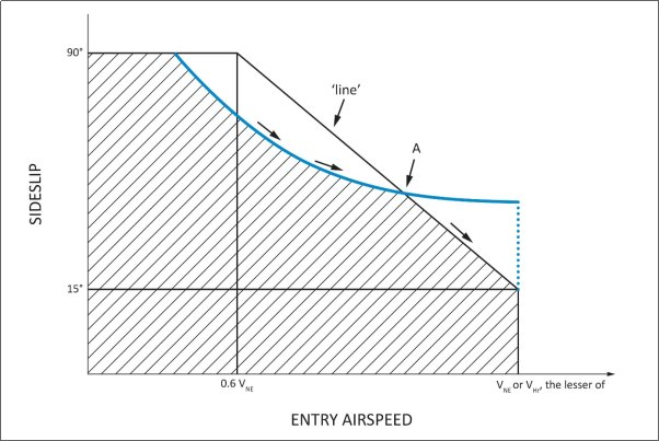
Figure 1 — YAW/FORWARD SPEED DIAGRAM
NOTE:
(1) When comparing the rotorcraft’s sideslip angle against the ‘line’ of Figure 1, the entry airspeed of the manoeuvre should be used.
(2) When evaluating the yawing condition against the ‘line’ of Figure 1, sufficient points should be investigated in order to determine the critical design conditions. This investigation should include the loads that result from the manoeuvre, specifically initiated at the intermediate airspeed which is coincident with the intersection of the ‘line’ and the resultant sideslip angle (point A in Figure 1).
(d) Another method of compliance may be used with a rational analysis (dynamic simulation), acceptable to the Agency/Authority, performed up to VH or VNE whichever is less, to the maximum yaw capability of the rotorcraft with recovery initiated at the resulting sideslip angle at its associated airspeed. Loads should be considered for all portions of the manoeuvre.
[Amdt 27/4]
AMC No 2 to 27.351 Yaw manoeuvre conditions
ED Decision 2016/024/R
1. Introduction
This AMC provides further guidance and acceptable means of compliance to supplement FAA AC 271B § AC 27.351. § 27.351 to meet the Agency's interpretation of CS 27.351. As such it should be used in conjunction with the FAA AC but take precedence over it, where stipulated, in the showing of compliance.
Specifically, this AMC addresses two areas where the FAA AC has been deemed by the Agency as being unclear or at variance to the Agency’s interpretation. These areas are as follows:
a. Aerodynamic Loads
The certification specification CS 27.351 provides a minimum safety standard for the design of rotorcraft structural components that are subjected in flight to critical loads combinations of antitorque system thrust (e.g. tail rotor), inertia and aerodynamics. A typical example of these structural components is the tailboom.
However, compliance with this standard according to FAA AC may not necessarily be adequate for the design of rotorcraft structural components that are principally subjected in flight to significant aerodynamic loads (e.g. vertical empennage, fins, cowlings and doors).
For these components and their supporting structure, suitable design criteria should be developed by the Applicant and agreed with the Agency.
In lieu of acceptable design criteria developed by the applicant, a suitable combination of sideslip angle and airspeed for the design of rotorcraft components subjected to aerodynamic loads may be obtained from a simulation of the yaw manoeuvre of CS 27.351, starting from the initial directional control input specified in CS 27.351(b)(1) and (c)(1), until the rotorcraft reaches the maximum transient sideslip angle (overswing) resulting from its motion around the yaw axis.
b. Interaction of System and Structure
Maximum displacement of the directional control, except as limited by pilot effort (CS 27.397(a)), is required for the conditions cited in the certification specification. In the load evaluation credit may be taken for consideration of the effects of control system limiting devices.
However, the probability of failure or malfunction of these system(s) should also be considered and if it is shown not to be extremely improbable then further load conditions with the system in the failed state should be evaluated. This evaluation may include Flight Manual Limitations, if failure of the system is reliably indicated to the crew.
A yaw limiting device is a typical example of a system whose failed condition should be investigated in the assessment of the loads requested by CS 27.351.
An acceptable methodology to investigate the effects of all system failures not shown to be extremely improbable on the loading conditions of CS 27.351 is as follows:
(i) With the system in the failed state and considering any appropriate reconfiguration and flight limitations, it should be shown that the rotorcraft structure can withstand without failure the loading conditions of CS 27.351, when the manoeuvre is performed in accordance with the provisions of this AMC.
(ii) The factor of safety to apply to the above specified loading conditions to comply with CS 27.305 is defined in the figure below.
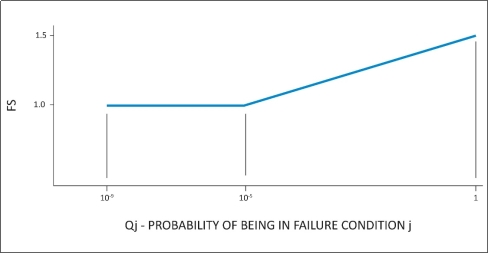
Qj = (Tj)(Pj)
where:
Tj = Average flight time spent with a failed limiting system j (in hours)
Pj = Probability of occurrence of failure of control limiting system j (per hour)
Note: If Pj is greater than 1x10³ per flight hour then a 1.5 factor of safety should be applied to all limit load conditions evaluated for the system failure under consideration.
[Amdt 27/2]
[Amdt 27/4]
ED Decision 2003/15/RM
(a) For turbine engines, the limit torque may not be less than the highest of:
(1) The mean torque for maximum continuous power multiplied by 1.25;
(2) The torque required by CS 27.923;
(3) The torque required by CS 27.927;
or
(4) The torque imposed by sudden engine stoppage due to malfunction or structural failure (such as compressor jamming).
(b) For reciprocating engines, the limit torque may not be less than the mean torque for maximum continuous power multiplied by:
(1) 1.33, for engines with five or more cylinders; and
(2) Two, three, and four, for engines with four, three, and two cylinders, respectively.