
Filters
Subpart C — Strength requirements
GENERAL
CS 29.301 Loads
ED Decision 2003/16/RM
(a)Strength requirements are specified in terms of limit loads (the maximum loads to be expected in service) and ultimate loads (limit loads multiplied by prescribed factors of safety). Unless otherwise provided, prescribed loads are limit loads.
(b)Unless otherwise provided, the specified air, ground, and water loads must be placed in equilibrium with inertia forces, considering each item of mass in the rotorcraft. These loads must be distributed to closely approximate or conservatively represent actual conditions.
(c)If deflections under load would significantly change the distribution of external or internal loads, this redistribution must be taken into account.
CS 29.303 Factor of safety
ED Decision 2003/16/RM
Unless otherwise provided, a factor of safety of 1.5 must be used. This factor applies to external and inertia loads unless its application to the resulting internal stresses is more conservative.
CS 29.305 Strength and deformation
ED Decision 2003/16/RM
(a)The structure must be able to support limit loads without detrimental or permanent deformation. At any load up to limit loads, the deformation may not interfere with safe operation.
(b)The structure must be able to support ultimate loads without failure. This must be shown by:
(1)Applying ultimate loads to the structure in a static test for at least 3 seconds; or
(2)Dynamic tests simulating actual load application.
CS 29.307 Proof of structure
ED Decision 2003/16/RM
(a)Compliance with the strength and deformation requirements of this Subpart must be shown for each critical loading condition accounting for the environment to which the structure will be exposed in operation. Structural analysis (static or fatigue) may be used only if the structure conforms to those for which experience has shown this method to be reliable. In other cases, substantiating load tests must be made.
(b)Proof of compliance with the strength requirements of this Subpart must include:
(1)Dynamic and endurance tests of rotors, rotor drives, and rotor controls;
(2)Limit load tests of the control system, including control surfaces;
(3)Operation tests of the control system;
(4)Flight stress measurement tests;
(5)Landing gear drop tests; and
(6)Any additional tests required for new or unusual design features.
AMC1 29.307 Proof of structure
ED Decision 2023/001/R
(a)Purpose
This AMC establishes methods of compliance with CS 29.307, which specifies the requirements for proof of structure.
(b)Related Certification Specifications
CS 29.303 ‘Factor of safety’
CS 29.305 ‘Strength and deformation’
(c)Definitions
(1)Detail: a structural element of a more complex structural member (e.g. gear teeth, joints, splices, stringers, stringer run-outs, lugs, or access holes).
(2)Subcomponent: a major three-dimensional structure which can provide a complete structural representation of a section of the full structure (e.g. main gearbox housing, gears, section of a blade, rotor spherical bearing, tension-torsion (TT) strap beams, or frames).
(3)Component: a major section of the airframe structure or mechanical assembly (e.g. main gearbox assembly, blade, main rotor hub assembly, cabin, tailboom, fin, horizontal stabiliser or transmission/upper deck) which can be tested as a complete unit to qualify the structure.
(4)Full scale: the dimensions of the test article are the same as design; fully representative test specimen (not necessarily complete airframe or mechanical assembly).
(5)New structure: a structure for which the behaviour is not adequately predicted by analysis supported by previous test evidence. A structure that utilises significantly different structural design concepts such as details, geometry, structural arrangements, and load paths or materials from previously tested designs.
(6)Similar new structure: a structure that utilises similar or comparable structural design concepts such as details, geometry, structural arrangements, and load path concepts and materials to an existing tested design.
(7)Derivative/similar structure: a structure that uses structural design concepts such as details, geometry, structural arrangements, and load paths, stress levels and materials that are nearly identical to those on which the analytical methods have been validated.
(8)Previous test evidence: testing of the original structure that is sufficient to verify the structural behaviour in accordance with CS 29.305.
(d)Introduction
As required by sub-paragraph (a) of CS 29.307, the structure must be shown to comply with the strength and deformation requirements of Subpart C of CS-29. This means that the structure must be able to support:
(a)limit loads without detrimental permanent deformation, and
(b)ultimate loads without failure.
This implies the need of a comprehensive assessment of the external loads (addressed by CS 29.301), the resulting internal strains and stresses, and the structural allowables.
CS 29.307 requires compliance for each critical loading condition. Compliance can be shown by analysis supported by previous test evidence, analysis supported by new test evidence or by test only. As compliance by test only is impractical in most cases, a large portion of the substantiating data will be based on analysis.
There are a number of standard engineering methods and formulas which are known to produce acceptable, often conservative, results especially for structures where load paths are well defined.
Those standard methods and formulas, applied with a good understanding of their limitations, are considered to be reliable analyses when showing compliance with CS 29.307. Conservative assumptions may be considered in assessing whether or not an analysis may be accepted without test substantiation.
The application of methods such as finite element method or engineering formulas to complex structures in modern aircraft is considered to be reliable only when validated by full-scale tests (ground and/or flight tests). Experience relevant to the product in the utilisation of such methods should be considered.
(e)Classification of structure
(a)The structure of the product should be classified into one of the following three categories:
(1)new structure
(2)similar new structure
(3)derivative/similar structure
(b)Justifications should be provided for classifications other than new structure. Elements that should be considered are:
(1)the accuracy/conservatism of the analytical methods; and
(2)comparison of the structure under investigation with a previously tested structure.
Considerations should include but are not limited to the following:
—external loads (bending moment, shear, torque, etc.);
—internal loads (strains, stresses, etc.);
—structural design concepts such as details, geometry, structural arrangements, load paths;
—materials;
—test experience (load levels achieved, lessons learned);
—deflections;
—deformations;
—extent of extrapolation from test stress levels.
(f)Need and extent of testing
The following factors should be considered in deciding the need for and the extent of testing including the load levels to be achieved:
(a)the classification of the structure (as above);
(b)the consequence of the failure of the structure in terms of the overall integrity of the rotorcraft;
(c)the consequence of the failure of interior items of mass and the supporting structure to the safety of the occupants.
Relevant service experience may be included in this evaluation.
(g)Certification approaches
The following certification approaches may be selected:
(a)Analysis, supported by new strength testing of the structure to limit and ultimate load. This is typically the case for a new structure.
Substantiation of the strength and deformation requirements up to limit and ultimate loads normally requires testing of subcomponents, full-scale components or full-scale tests of assembled components (such as a nearly complete airframe). The entire test programme should be considered in detail to ensure that the requirements for strength and deformation can be met up to limit load levels as well as ultimate load levels.
Sufficient limit load test conditions should be performed to verify that the structure meets the deformation requirements of CS 29.305(a) and to provide validation of internal load distribution and analysis predictions for all critical loading conditions.
Because ultimate load tests often result in significant permanent deformation, choices will have to be made with respect to the load conditions applied. This is usually based on the number of test specimens available, the analytical static strength margins of safety of the structure and the range of supporting detail or subcomponent tests. An envelope approach may be taken, where a combination of different load cases is applied, each one critical for a different section of the structure.
These limit and ultimate load tests may be supported by detail and subcomponent tests that verify the design allowables (tension, shear, compression) of the structure and often provide some degree of validation for ultimate strength.
(b)Analysis validated by previous test evidence and supported with additional limited testing. This is typically the case for a similar new structure.
The extent of additional limited testing (number of specimens, load levels, etc.) will depend upon the degree of change, relative to the elements of sub-paragraphs (e)(b)(1) and (2).
For example, if the changes to an existing design and analysis necessitate extensive changes to an existing test-validated finite element model (e.g. different rib spacing), additional testing may be needed. Previous test evidence can be relied upon whenever practical.
These additional limited tests may be further supported by detail and subcomponent tests that verify the design allowables (tension, shear, compression) of the structure and often provide some degree of validation for ultimate strength.
(c)Analysis, supported by previous test evidence. This is typically the case for a derivative/similar structure.
Justification should be provided for this approach by demonstrating how the previous static test evidence validates the analysis and supports showing compliance for the structure under investigation. Elements that need to be considered are those defined in sub-paragraphs (e)(b)(1) and (2).
For example, if the changes to the existing design and test-validated analysis are evaluated to ensure that they are relatively minor, and the effects of the changes are well understood, the original tests may provide sufficient validation of the analysis and further testing may not be necessary. For example, if a weight increase results in higher loads along with a corresponding increase in some of the element thickness and fastener sizes, and materials and geometry (overall configuration, spacing of structural members, etc.) remain generally the same, the revised analysis could be considered to be reliable based on the previous validation.
(d)Test only
Sometimes no reliable analytical method exists, and testing must be used to show compliance with the strength and deformation requirements. In other cases, it may be elected to show compliance solely by tests even if there are acceptable analytical methods. In either case, testing by itself can be used to show compliance with the strength and deformation requirements of CS-29 Subpart C. In such cases, the test load conditions should be selected to ensure that all critical design loads are encompassed.
If tests only are used to show compliance with the strength and deformation requirements for a single load path structure which carries flight loads, the test article should be of the minimum acceptable material quality or alternatively the test loads should be increased to account for variability in material properties. In lieu of a rational analysis, for metallic materials, a variability factor of 1.15 applied to the limit and ultimate flight loads may be used. If the structure has multiple load paths, no material correction factor is required.
(h)Interpretation of data
The interpretation of the substantiation analysis and test data requires an extensive review of:
the representativeness of the loading;
the instrumentation data;
comparisons with analytical methods;
the representativeness of the test article(s);
the test set-up (fixture, load introductions);
load levels and conditions tested;
test results.
Testing is used to validate analytical methods except when showing compliance by test only. If the test results do not correlate with the analysis, the reasons should be identified, and appropriate action taken.
This should be accomplished whether or not a test article fails below ultimate load.
Should a failure occur below ultimate load, an investigation should be conducted for the product to reveal the cause of this failure. This investigation should include a review of the test specimen and loads, analytical loads, and the structural analysis. This may lead to adjustment in analysis/modelling techniques and/or part redesign and may result in the need for additional testing. The need for additional testing to ensure that ultimate load capability depends on the degree to which the failure is understood, and the analysis can be validated by the test.
The approach described above is valid for static justification. However, a similar approach can be extended for compliance with fatigue, dynamic and crashworthiness requirements. For these applications, the criteria and the classification have to be accepted by and agreed with the authority.
[Amdt No: 29/11]
AMC2 29.307 Proof of structure
ED Decision 2023/001/R
FAIRING SUBSTANTIATION
This AMC supplements FAA AC 29-2C, § AC 29.307 and should be used in conjunction with that AC when demonstrating compliance with CS 29.307.
Further to CS 29.301, the specified loads must be distributed appropriately or conservatively and significant changes in the distribution of the loads, as a result of deflection, must be taken into account. FAA AC 29-2C, § AC 29.307 refers to the need for flight test measurement in the scope of the fatigue and damage tolerance demonstration. The methods used to determine load intensities and distribution should be validated by flight load measurements unless the methods used for determining those loading conditions are shown to be reliable.
Each fairing, when appropriate, should be constructed and supported so that it can resist any vibration, inertia, and air load to which it may be subjected in operation. The vibrations level, the inertia and air loads should be validated by appropriately instrumented flight measurements as recommended in FAA AC 29-2C, § AC 29.307.
For the fairings and the associated supporting structure, the loads can be shown unreliably predicted and require a measurement during flight tests.
The loads derived from flight testing should be compared with those obtained from analytical methods.
Note: AMC No.2 to CS 25.301(b) provides an acceptable means of demonstrating compliance with the provisions of CS-25 related to the validation, by flight measurements, of the methods used for determination of flight load intensities and distributions, for large aeroplanes.
The methodology presented in the CS-25 AMC material may be adapted to CS-29, to provide further guidance to this AMC.
[Amdt No: 29/11]
AMC3 29.307 Proof of structure
ED Decision 2023/001/R
SEAT ADAPTER PLATES
(a)Purpose
This AMC provides an acceptable means of compliance for seat adapter plates. The seat adapter plate includes any other forms of new interface structure installed between the seat and the rotorcraft floor.
(b)Related Certification Specifications
CS 29.307 ‘Proof of structure’
CS 29.561 ‘General’
CS 29.562 'Emergency landing dynamic conditions'
CS 29.785 ‘Seats, berths, safety belts, and harnesses’
(c)Explanation
The requirements for seats under emergency landing dynamic conditions have been developed to prevent detachment of the seat under floor deformation and for the seat to help absorb the energy developed in crash conditions. This dynamic condition has been addressed with the 10° roll and 10° pitch deformation required by CS 29.562(b)(3) to ensure that the seat and the floor attachments will be designed to accommodate deformation. This objective should be maintained when a seat adapter plate is installed between the seat and the floor.
Introducing an adapter plate can move the problems created by floor deformation from the seat-to-track interface to the adapter-to-floor interface. The same level of safety is appropriate for the occupant of the seat whether it is installed in the rotorcraft with or without an adapter plate. The floor structure itself is not subject to the dynamic requirements of CS 29.562, therefore when additional structure such as an adapter plate is introduced to fix the seat to the floor, it is very important to determine whether that structure should be considered to be part of the seat or part of the floor. The installation of any interface between the existing floor and the seat should not create a weak element between the seat and the existing airframe. This has successfully been ensured by testing the adapter with the seat according to the requirements of CS 29.562.
This AMC provides further guidance and acceptable means of compliance for classification of seat adapters, such as plinths or pallets, and supplements FAA § AC 25.562.
Plinths are subject to CS 29.562 compliance whereas pallets (traditionally defined as large adapters) are not, except for the attachment of the seat to the pallet.
FAA Policy Memo PS-ANM100-2000-00123 (which is applicable to CS-25 and can be extended to CS-29) suggests that it may also be possible to classify some smaller adapters as an integral part of the floor as follows:
‘Generally speaking, adapters of the size that contain a single row of seats (whether they are individual seat places or a common assembly), and mount into seat tracks, should be treated as part of the seat for purposes of certification in accordance with § 27/29.562. Larger, or more integrally mounted adapters, should be assessed to determine whether they should be treated as part of the floor for purposes of certification in accordance with § 27/29.561.’
To treat an adapter or other new interface structure as part of the floor when it does not appear to be similar to conventional floor structure, the applicant must substantiate that the adapter plate or any other structure installed between the existing floor and the seat attachment will not constitute a weak element under emergency landing conditions. The issue is whether the critical interface is between the seat and the adapter or between the adapter and the rotorcraft. No further detailed guidance is available to assist with the assessment required to make the classification of an adapter as part of the floor.
Where the proposed floor design utilises a plate above the existing floor or otherwise significantly differs in concept from the type design’s existing methods of floor construction, geometries and utilisation of load paths, it is not adequate to rely on compliance with CS 29.561 alone to determine whether the adapter plate may be considered to be part of the floor. This guidance does not intend to request a complete crash scenario evaluation, but asks for evidence that the adapter plate and associated new under floor structure will not degrade the level of protection compared to that offered by the seat if it were installed directly on the helicopter existing floor seat track and floor construction. For an adapter plate to be considered sufficiently integrated to be part of the floor, the adapter plate should be capable of accommodating floor deformation and be able to safely react and distribute the seat loads into the rotorcraft.
(d)Seat adapter plate definition and classification
(1)Definition
The definition of plinth and pallet available in AC 25.562(b) is valid.
In general, swivelling seat adapter plate systems are by definition considered to be plinths.
(2)Classification
There are three possible options for the seat-to-floor interface with corresponding means of compliance. In each case, the applicant is requested to show that any interface between the existing floor and the seat will not create a weaker element between the seat and the existing airframe than that that would exist for a CS 29.562-compliant seat attached directly to the standard floor, e.g. seat track.
Acceptable means of assessing seat installations using adapter plates:
Option 1
—The adapter is classified as a plinth following AC 25.562-1B.
—Compliance with CS 29.561 and CS 29.562 must be shown.
—The plinth must be tested as part of the seat according to CS 29.562(b)(1) and (b)(2) unless alternative compliance is agreed as per CS 29.562(d).
—The guidance of AC 25.562-1B and AMC 29.307 may be used to reduce the number of tests based on design similarity.
Option 2
—The adapter is classified as a pallet due to its size following AC 25.562-1B.
—The seat and its attachments to the pallet only are tested according to CS 29.562 and CS 29.561.
—The pallet is justified against CS 29.561 only.
Option 3
—If neither Option 1 nor 2 clearly apply, seat-to-floor interface structure is proposed to be classified as an integral part of the floor based on one of the methods described below.
—If classification as part of the floor is agreed with the Agency, the seat and its attachments to the structure are tested according to CS 29.562, and compliance with CS 29.561 is shown for the whole installation.
Acceptable methods to be used in support of Option 3, allowing classification of the new seat-to-floor interface structure as an integral part of the floor structure:
Method 1
A design review showing the floor design for seat installation uses the same or an equivalent design principle as the current floor provided in the type design. If the pre-existing floor design used seats directly attached to seat track independently of the floor panel, then the introduction of a structural floor panel to which a seat is attached would represent a change in design philosophy, and a different method (e.g. Method 2) would need to be used to support Option 3.
Method 2
A detailed design review showing the level of integration of the plate to the floor, including the redundancy and strength of the attachments, that is acceptable to the Agency based on the experience of the applicant and the Agency with similar designs.
Any other alternative methods have to be agreed with the Agency.
Note:
When assessing the design, the following points should be considered by the applicant and the Agency, in particular for design change certification:
—The modified structure may be evaluated using AMC1 29.307 to categorise the structural elements as new, similar-new or similar. Comparison can be made with the existing type floor design (Method 1) or with designs that the applicant has previously substantiated according to Method 2.
—An adequate number of appropriately distributed attachments between the adapter plate and the rotorcraft floor structure must be provided to ensure that the additional structure behaves as an integral part of the rotorcraft floor. The appropriate number, strength and degree of redundancy of the attachments will depend on the design of the adapter plate and positioning of the seats on the plate.
—A considerable degree of engineering judgement is required when making the classification of the structure; when there is any doubt about the capability of the proposed adapter design to act as an integral part of the floor, it will be classified as a plinth under Option 1.
[Amdt No: 29/11]
CS 29.309 Design limitations
ED Decision 2023/001/R
The following values and limitations must be established to show compliance with the structural requirements of this Subpart:
(a)The design maximum and design minimum weights.
(b)The main rotor rpm ranges, power on and power off.
(c)The maximum forward speeds for each main rotor rpm within the ranges determined under sub-paragraph (b).
(d)The maximum rearward and sideward flight speeds.
(e)The centre of gravity limits corresponding to the limitations determined under sub-paragraphs (b), (c) and (d).
(f)The rotational speed ratios between each powerplant and each connected rotating component.
(g)The positive and negative limit manoeuvring load factors.
(h)The maximum and minimum density altitude and temperatures.
[Amdt No: 29/11]
FLIGHT LOADS
CS 29.321 General
ED Decision 2003/16/RM
(a)The flight load factor must be assumed to act normal to the longitudinal axis of the rotorcraft, and to be equal in magnitude and opposite in direction to the rotorcraft inertia load factor at the centre of gravity.
(b)Compliance with the flight load requirements of this Subpart must be shown:
(1)At each weight from the design minimum weight to the design maximum weight; and
(2)With any practical distribution of disposable load within the operating limitations in the rotorcraft flight manual.
CS 29.337 Limit manoeuvring load factor
ED Decision 2003/16/RM
The rotorcraft must be designed for –
(a)A limit manoeuvring load factor ranging from a positive limit of 3.5 to a negative limit of -1.0; or
(b)Any positive limit manoeuvring load factor not less than 2.0 and any negative limit manoeuvring load factor of not less than –0.5 for which:
(1)The probability of being exceeded is shown by analysis and flight tests to be extremely remote; and
(2)The selected values are appropriate to each weight condition between the design maximum and design minimum weights.
AMC1 29.337 Limit manoeuvring load factor
ED Decision 2023/001/R
This AMC supplements FAA AC 29-2C, § AC 29.337 and should be used in conjunction with that AC when demonstrating compliance with CS 29.337 for determining the positive limit manoeuvring load factor.
In accordance with CS 29.337, the rotorcraft may be substantiated to a maximum positive load factor less than +3.5 (but not less than 2.0) provided that the probability of being exceeded is shown to be extremely remote. Whenever this option is selected, the maximum available rotor lift with both power on and power off rotor speed ranges throughout the entire operational density envelope should be considered.
AC 29-2C, § AC 29.337(b)(1) provides some guidance as to the necessary considerations when substantiating manoeuvre load factors less than the specified values. Further clarification should be provided in this paragraph to specify that the entire operational envelope should be considered when determining the maximum available rotor lift.
There, the guidance should be read as follows:
§ AC 29.337(b)(1) The applicant may elect to substantiate the rotorcraft for a design manoeuvring load factor less than +3.5 and more than -1.0. Whenever this option is used, an analytical study and flight demonstration are required. Maximum available rotor lift with both power on and power off throughout the entire operational density envelope should be considered when substantiating manoeuvre load factors less than the specified values.
[Amdt No: 29/11]
CS 29.339 Resultant limit manoeuvring loads
ED Decision 2003/16/RM
The loads resulting from the application of limit manoeuvring load factors are assumed to act at the centre of each rotor hub and at each auxiliary lifting surface, and to act in directions and with distributions of load among the rotors and auxiliary lifting surfaces, so as to represent each critical manoeuvring condition, including power-on and power-off flight with the maximum design rotor tip speed ratio. The rotor tip speed ratio is the ratio of the rotorcraft flight velocity component in the plane of the rotor disc to the rotational tip speed of the rotor blades and is expressed as follows:
where:
V = The airspeed along the flight path (m/s (fps));
a = The angle between the projection, in the plane of symmetry, of the axis of no feathering and a line perpendicular to the flight path (radians, positive when axis is pointing aft);
Ω = The angular velocity of rotor (radians per second); and
R = The rotor radius (m (ft)).
CS 29.341 Gust loads
ED Decision 2003/16/RM
Each rotorcraft must be designed to withstand, at each critical airspeed including hovering, the loads resulting from vertical and horizontal gusts of 9.1 metres per second (30 ft/s).
CS 29.351 Yawing conditions
ED Decision 2003/16/RM
(a)Each rotorcraft must be designed for the loads resulting from the manoeuvres specified in sub-paragraphs (b) and (c), with:
(1)Unbalanced aerodynamic moments about the centre of gravity which the aircraft reacts to in a rational or conservative manner considering the principal masses furnishing the reacting inertia forces; and
(2)Maximum main rotor speed.
(b)To produce the load required in sub-paragraph (a), in unaccelerated flight with zero yaw, at forward speeds from zero up to 0.6 VNE.
(1)Displace the cockpit directional control suddenly to the maximum deflection limited by the control stops or by the maximum pilot force specified in CS 29.397(a);
(2)Attain a resulting sideslip angle or 90°, whichever is less; and
(3)Return the directional control suddenly to neutral.
(c)To produce the load required in sub-paragraph (a), in unaccelerated flight with zero yaw, at forward speeds from 0.6 VNE up to VNE or VH, whichever is less:
(1)Displace the cockpit directional control suddenly to the maximum deflection limited by the control stops or by the maximum pilot force specified in CS 29.397(a);
(2)Attain a resulting sideslip angle or 15°, whichever is less, at the lesser speed of VNE or VH;
(3)Vary the sideslip angles of sub-paragraphs (b)(2) and (c)(2) directly with speed; and
(4)Return the directional control suddenly to neutral.
AMC No 1 to CS 29.351 Yawing conditions
ED Decision 2016/025/R
(a)Definitions
(1)Suddenly. For the purpose of this AMC, ‘suddenly’ is defined as an interval not to exceed 0.2 seconds for a complete control input. A rational analysis may be used to substantiate an alternative value.
(2)Initial Trim Condition. Steady, 1G, level flight condition with zero bank angle or zero sideslip.
(3)‘Line’. The rotorcraft’s sideslip envelope, defined by the rule, between 90° at 0.6VNE and 15° at VNE or VH whichever is less (see Figure 1).
(4)Resulting Sideslip Angle. The rotorcraft’s stabilised sideslip angle that results from a sustained maximum cockpit directional control deflection or as limited by pilot effort in the initial level flight power conditions.
(b)Explanation. The rule requires a rotorcraft’s ‘structural’ yaw or sideslip design envelope that must cover a minimum forward speed or hover to VNE or VH whichever is less. The scope of the rule is intended to cover structural components that are primarily designed for the critical combinations of tail rotor thrust, inertial and aerodynamic forces. This may include but is not limited to fuselage, tailboom and attachments, vertical control surfaces, tail rotor and tail rotor support structure.
(1)The rotorcraft’s structure must be designed to withstand the loads in the specified yawing conditions. The standard does not require a structural flight demonstration. It is a structural design standard.
(2)The standard applies only to power-on conditions. Autorotation need not be considered.
(3)This standard requires the maximum allowable rotor revolutions per minute (RPM) consistent with each flight condition for which certification is requested.
(4)For the purpose of this AMC, the analysis may be performed in international standard atmosphere (ISA) sea level conditions.
(5)Maximum displacement of the directional control, except as limited by pilot effort (29.397(a)), is required for the conditions cited in the rule. A control-system-limiting device may be used, however the probability of failure or malfunction of these system(s) should be considered (See AMC No 2 to CS 29.351 Interaction of System and Structure).
(6)Both right and left yaw conditions should be evaluated.
(7)The airloads on the vertical stabilisers may be assumed independent of the tail rotor thrust.
(8)Loads associated with sideslip angles exceeding the values of the ‘line’, defined in Figure 1, do not need to be considered. The corresponding points of the manoeuvre may be deleted.
(c)Procedure. The design loads should be evaluated within the limits of Figure 1 or the maximum yaw capability of the rotorcraft, whichever is less; at speeds from zero to VH or VNE, whichever is less, for the following phases of the manoeuvre (see Note 1):
(1)With the rotorcraft at an initial trim condition, the cockpit directional control is suddenly displaced to the maximum deflection limited by the control stops or by the maximum pilot force specified in 29.397(a). This is intended to generate a high tail rotor thrust.
(2)While maintaining maximum cockpit directional control deflection, within the limitation specified in (c)(1) of this AMC allow the rotorcraft to yaw to the maximum transient sideslip angle. This is intended to generate high aerodynamic loads that are determined based on the maximum transient sideslip angle or the value defined by the ‘line’ in Figure 1 whichever is less (see Note 1).
(3)Allow the rotorcraft to attain the resulting sideslip angle. In the event that the resulting sideslip angle is greater than the value defined by the ‘line’ in Figure 1, the rotorcraft should be trimmed to that value of the angle using less than maximum cockpit directional-control deflection by taking into consideration the manoeuvre’s entry airspeed (see Note 2).
(4)With the rotorcraft yawed to the resulting sideslip angle specified in (c)(3) of this AMC the cockpit control is suddenly returned to its initial trim position. This is intended to combine a high tail rotor thrust and high aerodynamic restoring forces.

Figure 1 — YAW/FORWARD SPEED DIAGRAM
NOTE:
(1)When comparing the rotorcraft’s sideslip angle against the ‘line’ of Figure 1, the entry airspeed of the manoeuvre should be used.
(2)When evaluating the yawing condition against the ‘line’ of Figure 1, sufficient points should be investigated in order to determine the critical design conditions. This investigation should include the loads that result from the manoeuvre, specifically initiated at the intermediate airspeed which is coincident with the intersection of the ‘line’ and the resultant sideslip angle (point A in Figure 1).
(d)Another method of compliance may be used with a rational analysis (dynamic simulation), acceptable to the Agency/Authority, performed up to VH or VNE whichever is less, to the maximum yaw capability of the rotorcraft with recovery initiated at the resulting sideslip angle at its associated airspeed. Loads should be considered for all portions of the manoeuvre.
[Amdt 29/4]
AMC No 2 to CS 29.351 Yaw manoeuvre conditions
ED Decision 2016/025/R
1.Introduction
This AMC provides further guidance and acceptable means of compliance to supplement FAA AC 292C § AC 29.351b. § 29.351 to meet the Agency's interpretation of CS 29.351. As such it should be used in conjunction with the FAA AC but take precedence over it, where stipulated, in the showing of compliance.
Specifically, this AMC addresses two areas where the FAA AC has been deemed by the Agency as being unclear or at variance to the Agency’s interpretation. These areas are as follows:
a. Aerodynamic Loads
The certification specification CS 29.351 provides a minimum safety standard for the design of rotorcraft structural components that are subjected in flight to critical loads combinations of antitorque system thrust (e.g. tail rotor), inertia and aerodynamics. A typical example of these structural components is the tailboom.
However, compliance with this standard according to FAA AC may not necessarily be adequate for the design of rotorcraft structural components that are principally subjected in flight to significant aerodynamic loads (e.g. vertical empennage, fins, cowlings and doors).
For these components and their supporting structure, suitable design criteria should be developed by the Applicant and agreed with the Agency.
In lieu of acceptable design criteria developed by the applicant, a suitable combination of sideslip angle and airspeed for the design of rotorcraft components subjected to aerodynamic loads may be obtained from a simulation of the yaw manoeuvre of CS 29.351, starting from the initial directional control input specified in CS 29.351(b)(1) and (c)(1), until the rotorcraft reaches the maximum transient sideslip angle (overswing) resulting from its motion around the yaw axis.
b. Interaction of System and Structure
Maximum displacement of the directional control, except as limited by pilot effort (CS 29.397(a)), is required for the conditions cited in the certification specification. In the load evaluation credit may be taken for consideration of the effects of control system limiting devices.
However, the probability of failure or malfunction of these system(s) should also be considered and if it is shown not to be extremely improbable then further load conditions with the system in the failed state should be evaluated. This evaluation may include Flight Manual Limitations, if failure of the system is reliably indicated to the crew.
A yaw limiting device is a typical example of a system whose failed condition should be investigated in the assessment of the loads requested by CS 29.351.
An acceptable methodology to investigate the effects of all system failures not shown to be extremely improbable on the loading conditions of CS 29.351 is as follows:
(i)With the system in the failed state and considering any appropriate reconfiguration and flight limitations, it should be shown that the rotorcraft structure can withstand without failure the loading conditions of CS 29.351, when the manoeuvre is performed in accordance with the provisions of the this AMC.
(ii)The factor of safety to apply to the above specified loading conditions to comply with CS 29.305 is defined in the figure below.
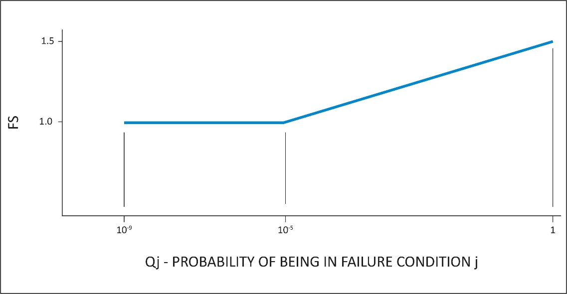
Qj = (Tj)(Pj)
where:
Tj = Average flight time spent with a failed limiting system j (in hours)
Pj = Probability of occurrence of failure of control limiting system j (per hour)
Note: If Pj is greater than 1x10³ per flight hour then a 1.5 factor of safety should be applied to all limit load conditions evaluated for the system failure under consideration.
[Amdt 29/2]
[Amdt 29/4]
CS 29.361 Engine torque
ED Decision 2003/16/RM
The limit engine torque may not be less than the following:
(a)For turbine engines, the highest of:
(1)The mean torque for maximum continuous power multiplied by 1.25;
(2)The torque required by CS 29.923;
(3)The torque required by CS 29.927; or
(4)The torque imposed by sudden engine stoppage due to malfunction or structural failure (such as compressor jamming).
(b)For reciprocating engines, the mean torque for maximum continuous power multiplied by:
(1)1.33, for engines with five or more cylinders; and
(2)Two, three, and four, for engines with four, three, and two cylinders, respectively.
CONTROL SURFACE AND SYSTEM LOADS
CS 29.391 General
ED Decision 2003/16/RM
Each auxiliary rotor, each fixed or movable stabilising or control surface, and each system operating any flight control must meet the requirements of CS 29.395 to 29.427.
CS 29.395 Control system
ED Decision 2003/16/RM
(a)The reaction to the loads prescribed in CS 29.397 must be provided by:
(1)The control stops only;
(2)The control locks only;
(3)The irreversible mechanism only (with the mechanism locked and with the control surface in the critical positions for the effective parts of the system within its limit of motion);
(4)The attachment of the control system to the rotor blade pitch control horn only (with the control in the critical positions for the affected parts of the system within the limits of its motion); and
(5)The attachment of the control system to the control surface horn (with the control in the critical positions for the affected parts of the system within the limits of its motion).
(b)Each primary control system, including its supporting structure, must be designed as follows:
(1)The system must withstand loads resulting from the limit pilot forces prescribed in CS 29.397;
(2)Notwithstanding sub-paragraph (b)(3), when power-operated actuator controls or power boost controls are used, the system must also withstand the loads resulting from the limit pilot forces prescribed in CS 29.397 in conjunction with the forces output of each normally energised power device, including any single power boost or actuator system failure;
(3)If the system design or the normal operating loads are such that a part of the system cannot react to the limit pilot forces prescribed in CS 29.397, that part of the system must be designed to withstand the maximum loads that can be obtained in normal operation. The minimum design loads must, in any case, provide a rugged system for service use, including consideration of fatigue, jamming, ground gusts, control inertia and friction loads. In the absence of a rational analysis, the design loads resulting from 0.60 of the specified limit pilot forces are acceptable minimum design loads; and
(4)If operational loads may be exceeded through jamming, ground gusts, control inertia, or friction, the system must withstand the limit pilot forces specified in CS 29.397, without yielding.
AMC1 29.395 Control system
ED Decision 2023/001/R
This AMC supplements FAA AC 29-2C, § AC 29.395 and should be used in conjunction with that AC when demonstrating compliance with CS 29.395.
The design reaction loads prescribed in CS 29.395 for the flight control system should apply to the part of the control system from the pilot cockpit control sticks/pedals to the main/tail rotor servo-actuators. The remaining part of the flight control systems located between the attachment of the servo-actuators and the (main/tail) blades (i.e. rotating parts, servo-actuators and their attachments) should be substantiated to the highest of:
—maximum loads expected in service (limit loads) as per CS 29.301, CS 29.305 and CS 29.547 (nominal conditions);
—maximum loads for a single failure of the hydraulic system leading to an operating hydraulic overpressure;
—the maximum loads due to a jamming of the flight control system (rotating parts).
The maximum pilot loads from CS 29.397 to CS 29.399 should be added to these loads appropriately.
[Amdt No: 29/11]
CS 29.397 Limit pilot forces and torques
ED Decision 2003/16/RM
(a)Except as provided in sub-paragraph (b), the limit pilot forces are as follows:
(1)For foot controls, 578 N (130 lbs).
(2)For stick controls, 445 N (100 lbs) fore and aft, and 298 N (67 lbs) laterally.
(b)For flap, tab, stabiliser, rotor brake and landing gear operating controls, the following apply:
(1)Crank, wheel, and lever controls, (25.4 + R) x 2.919 N, where R = radius in millimetres (, where R = radius in inches), but not less than 222 N (50 lbs) nor more than 445 N (100 lbs) for hand-operated controls or 578 N (130 lbs) for foot-operated controls, applied at any angle within 20° of the plane of motion of the control.
(2)Twist controls, 356 x R Newton-millimetres, where R = radius in millimetres (80 x R inch-pounds where R = radius in inches).
CS 29.399 Dual control system
ED Decision 2003/16/RM
Each dual primary flight control system must be able to withstand the loads that result when pilot forces not less than 0.75 times those obtained under CS 29.395 are applied:
(a)In opposition; and
(b)In the same direction.
CS 29.411 Ground clearance: tail rotor guard
ED Decision 2003/16/RM
(a)It must be impossible for the tail rotor to contact the landing surface during a normal landing.
(b)If a tail rotor guard is required to show compliance with sub-paragraph (a):
(1)Suitable design loads must be established for the guard; and
(2)The guard and its supporting structure must be designed to withstand those loads.
CS 29.427 Unsymmetrical loads
ED Decision 2003/16/RM
(a)Horizontal tail surfaces and their supporting structure must be designed for unsymmetrical loads arising from yawing and rotor wake effects in combination with the prescribed flight conditions.
(b)To meet the design criteria of sub-paragraph (a), in the absence of more rational data, both of the following must be met:
(1)100% of the maximum loading from the symmetrical flight conditions acts on the surface on one side of the plane of symmetry, and no loading acts on the other side.
(2)50% of the maximum loading from the symmetrical flight conditions acts on the surface on each side of the plane of symmetry, in opposite directions.
(c)For empennage arrangements where the horizontal tail surfaces are supported by the vertical tail surfaces, the vertical tail surfaces and supporting structure must be designed for the combined vertical and horizontal surface loads resulting from each prescribed flight condition, considered separately. The flight conditions must be selected so that the maximum design loads are obtained on each surface. In the absence of more rational data, the unsymmetrical horizontal tail surface loading distributions described in this paragraph must be assumed.
AMC1 29.427 Unsymmetrical loads
ED Decision 2023/001/R
This AMC supplements FAA AC 29-2C, § AC 29.427 and should be used in conjunction with that AC when demonstrating compliance with CS 29.427.
In case of load distribution deviating from CS 29.427(b), the applicant should provide the rationale justifying that the selected load distribution conservatively addresses the limit flight load conditions of Subpart C. Dedicated flight load and/or wind tunnel measurements should be performed to confirm the suitability of the proposed criteria.
[Amdt No: 29/11]
GROUND LOADS
CS 29.471 General
ED Decision 2003/16/RM
(a)Loads and equilibrium. For limit ground loads:
(1)The limit ground loads obtained in the landing conditions in this CS-29 must be considered to be external loads that would occur in the rotorcraft structure if it were acting as a rigid body; and
(2)In each specified landing condition, the external loads must be placed in equilibrium with linear and angular inertia loads in a rational or conservative manner.
(b)Critical centres of gravity. The critical centres of gravity within the range for which certification is requested must be selected so that the maximum design loads are obtained in each landing gear element.
CS 29.473 Ground loading conditions and assumptions
ED Decision 2003/16/RM
(a)For specified landing conditions, a design maximum weight must be used that is not less than the maximum weight. A rotor lift may be assumed to act through the centre of gravity throughout the landing impact. This lift may not exceed two- thirds of the design maximum weight.
(b)Unless otherwise prescribed, for each specified landing condition, the rotorcraft must be designed for a limit load factor of not less than the limit inertia load factor substantiated under CS 29.725.
(c)Triggering or actuating devices for additional or supplementary energy absorption may not fail under loads established in the tests prescribed in CS 29.725 and 29.727, but the factor of safety prescribed in CS 29.303 need not be used.
CS 29.475 Tyres and shock absorbers
ED Decision 2003/16/RM
Unless otherwise prescribed, for each specified landing condition, the tyres must be assumed to be in their static position and the shock absorbers to be in their most critical position.
CS 29.477 Landing gear arrangement
ED Decision 2003/16/RM
Paragraphs CS 29.235, 29.479 to 29.485, and 29.493 apply to landing gear with two wheels aft, and one or more wheels forward, of the centre of gravity.
CS 29.479 Level landing conditions
ED Decision 2003/16/RM
(a)Attitudes. Under each of the loading conditions prescribed in sub-paragraph (b), the rotorcraft is assumed to be in each of the following level landing attitudes:
(1)An attitude in which each wheel contacts the ground simultaneously.
(2)An attitude in which the aft wheels contact the ground with the forward wheels just clear of the ground.
(b)Loading conditions. The rotorcraft must be designed for the following landing loading conditions:
(1)Vertical loads applied under CS 29.471.
(2)The loads resulting from a combination of the loads applied under sub-paragraph (b)(1) with drag loads at each wheel of not less than 25% of the vertical load at that wheel.
(3)The vertical load at the instant of peak drag load combined with a drag component simulating the forces required to accelerate the wheel rolling assembly up to the specified ground speed, with:
(i)The ground speed for determination of the spin-up loads being at least 75% of the optimum forward flight speed for minimum rate of descent in autorotation; and
(ii)The loading conditions of sub-paragraph (b) applied to the landing gear and its attaching structure only.
(4)If there are two wheels forward, a distribution of the loads applied to those wheels under sub-paragraphs (b)(1) and (2) in a ratio of 40:60.
(c)Pitching moments. Pitching moments are assumed to be resisted by:
(1)In the case of the attitude in sub-paragraph (a)(1), the forward landing gear; and
(2)In the case of the attitude in sub-paragraph (a)(2), the angular inertia forces.
CS 29.481 Tail-down landing conditions
ED Decision 2003/16/RM
(a)The rotorcraft is assumed to be in the maximum nose-up attitude allowing ground clearance by each part of the rotorcraft.
(b)In this attitude, ground loads are assumed to act perpendicular to the ground.
CS 29.483 One-wheel landing conditions
ED Decision 2003/16/RM
For the one-wheel landing condition, the rotorcraft is assumed to be in the level attitude and to contact the ground on one aft wheel. In this attitude:
(a)The vertical load must be the same as that obtained on that side under CS 29.479(b)(1); and
(b)The unbalanced external loads must be reacted by rotorcraft inertia.
CS 29.485 Lateral drift landing conditions
ED Decision 2003/16/RM
(a)The rotorcraft is assumed to be in the level landing attitude, with:
(1)Side loads combined with one-half of the maximum ground reactions obtained in the level landing conditions of CS 29.479(b)(1); and
(2)The loads obtained under sub-paragraph (a)(1) applied:
(i)At the ground contact point; or
(ii)For full-swivelling gear, at the centre of the axle.
(b)The rotorcraft must be designed to withstand, at ground contact:
(1)When only the aft wheels contact the ground, side loads of 0.8 times the vertical reaction acting inward on one side and 0.6 times the vertical reaction acting outward on the other side, all combined with the vertical loads specified in sub-paragraph (a); and
(2)When the wheels contact the ground simultaneously:
(i)For the aft wheels, the side loads specified in sub-paragraph (b)(1); and
(ii)For the forward wheels, a side load of 0.8 times the vertical reaction combined with the vertical load specified in sub-paragraph (a).
CS 29.493 Braked roll conditions
ED Decision 2003/16/RM
Under braked roll conditions with the shock absorbers in their static positions:
(a)The limit vertical load must be based on a load factor of at least –
(1)1.33, for the attitude specified in CS 29.479(a)(1); and
(2)1.0, for the attitude specified in CS 29.479(a)(2); and
(b)The structure must be designed to withstand, at the ground contact point of each wheel with brakes, a drag load of at least the lesser of:
(1)The vertical load multiplied by a coefficient of friction of 0.8; and
(2)The maximum value based on limiting brake torque.
CS 29.497 Ground loading conditions: landing gear with tail wheels
ED Decision 2003/16/RM
(a)General. Rotorcraft with landing gear with two wheels forward and one wheel aft of the centre of gravity must be designed for loading conditions as prescribed in this paragraph..
(b)Level landing attitude with only the forward wheels contacting the ground. In this attitude:
(1)The vertical loads must be applied under CS 29.471 to CS 29.475;
(2)The vertical load at each axle must be combined with a drag load at that axle of not less than 25% of that vertical load; and
(3)Unbalanced pitching moments are assumed to be resisted by angular inertia forces.
(c)Level landing attitude with all wheels contacting the ground simultaneously. In this attitude, the rotorcraft must be designed for landing loading conditions as prescribed in sub-paragraph (b).
(d)Maximum nose-up attitude with only the rear wheel contacting the ground. The attitude for this condition must be the maximum nose-up attitude expected in normal operation, including autorotative landings. In this attitude:
(1)The appropriate ground loads specified in sub-paragraphs (b)(1) and (2) must be determined and applied, using a rational method to account for the moment arm between the rear wheel ground reaction and the rotorcraft centre of gravity; or
(2)The probability of landing with initial contact on the rear wheel must be shown to be extremely remote.
(e)Level landing attitude with only one forward wheel contacting the ground. In this attitude, the rotorcraft must be designed for ground loads as specified in sub-paragraphs (b)(1) and (3).
(f)Side loads in the level landing attitude. In the attitudes specified in sub-paragraphs (b) and (c), the following apply:
(1)The side loads must be combined at each wheel with one-half of the maximum vertical ground reactions obtained for that wheel under sub-paragraphs (b) and (c). In this condition, the side loads must be:
(i)For the forward wheels, 0.8 times the vertical reaction (on one side) acting inward and 0.6 times the vertical reaction (on the other side) acting outward; and
(ii)For the rear wheel, 0.8 times the vertical reaction.
(2)The loads specified in sub-paragraph (f)(1) must be applied:
(i)At the ground contact point with the wheel in the trailing position (for non-full swivelling landing gear or for full swivelling landing gear with a lock, steering device, or shimmy damper to keep the wheel in the trailing position); or
(ii)At the centre of the axle (for full swivelling landing gear without a lock, steering device, or shimmy damper).
(g)Braked roll conditions in the level landing attitude. In the attitudes specified in sub- paragraphs (b) and (c), and with the shock absorbers in their static positions, the rotorcraft must be designed for braked roll loads as follows:
(1)The limit vertical load must be based on a limit vertical load factor of not less than:
(i)1.0, for the attitude specified in sub-paragraph (b); and
(ii)1.33, for the attitude specified in sub-paragraph (c).
(2)For each wheel with brakes, a drag load must be applied, at the ground contact point, of not less than the lesser of:
(i)0.8 times the vertical load; and
(ii)The maximum based on limiting brake torque.
(h)Rear wheel turning loads in the static ground attitude. In the static ground attitude, and with the shock absorbers and tyres in their static positions, the rotorcraft must be designed for rear wheel turning loads as follows:
(1)A vertical ground reaction equal to the static load on the rear wheel must be combined with an equal side load.
(2)The load specified in sub-paragraph (h)(1) must be applied to the rear landing gear:
(i)Through the axle, if there is a swivel (the rear wheel being assumed to be swivelled 90°, to the longitudinal axis of the rotorcraft); or
(ii)At the ground contact point if there is a lock, steering device or shimmy damper (the rear wheel being assumed to be in the trailing position).
(i)Taxying condition. The rotorcraft and its landing gear must be designed for the loads that would occur when the rotorcraft is taxied over the roughest ground that may reasonably be expected in normal operation.
CS 29.501 Ground loading conditions: landing gear with skids
ED Decision 2003/16/RM
(a)General. Rotorcraft with landing gear with skids must be designed for the loading conditions specified in this paragraph. In showing compliance with this paragraph, the following apply:
(1)The design maximum weight, centre of gravity, and load factor must be determined under CS 29.471 to 29.475.
(2)Structural yielding of elastic spring members under limit loads is acceptable.
(3)Design ultimate loads for elastic spring members need not exceed those obtained in a drop test of the gear with:
(i)A drop height of 1.5 times that specified in CS 29.725; and
(ii)An assumed rotor lift of not more than 1.5 times that used in the limit drop tests prescribed in CS 29.725.
(4)Compliance with sub-paragraphs (b) to (e) must be shown with:
(i)The gear in its most critically deflected position for the landing condition being considered; and
(ii)The ground reactions rationally distributed along the bottom of the skid tube.
(b)Vertical reactions in the level landing attitude. In the level attitude, and with the rotorcraft contacting the ground along the bottom of both skids, the vertical reactions must be applied as prescribed in sub-paragraph (a).
(c)Drag reactions in the level landing attitude. In the level attitude, and with the rotorcraft contacting the ground along the bottom of both skids, the following apply:
(1)The vertical reactions must be combined with horizontal drag reactions of 50% of the vertical reaction applied at the ground.
(2)The resultant ground loads must equal the vertical load specified in sub-paragraph (b).
(d)Sideloads in the level landing attitude. In the level attitude, and with the rotorcraft contacting the ground along the bottom of both skids, the following apply:
(1)The vertical ground reaction must be:
(i)Equal to the vertical loads obtained in the condition specified in sub-paragraph (b); and
(ii)Divided equally among the skids.
(2)The vertical ground reactions must be combined with a horizontal sideload of 25% of their value.
(3)The total sideload must be applied equally between skids and along the length of the skids.
(4)The unbalanced moments are assumed to be resisted by angular inertia.
(5)The skid gear must be investigated for:
(i)Inward acting sideloads; and
(ii)Outward acting sideloads.
(e)One-skid landing loads in the level attitude. In the level attitude, and with the rotorcraft contacting the ground along the bottom of one skid only, the following apply:
(1)The vertical load on the ground contact side must be the same as that obtained on that side in the condition specified in sub-paragraph (b).
(2)The unbalanced moments are assumed to be resisted by angular inertia.
(f)Special conditions. In addition to the specified in sub-paragraphs (b) and (c), the rotorcraft must be designed for the following ground reactions:
(1)A ground reaction load acting up and aft at an angle of 45°, to the longitudinal axis of the rotorcraft. This load must be:
(i)Equal to 1.33 times the maximum weight;
(ii)Distributed symmetrically among the skids;
(iii)Concentrated at the forward end of the straight part of the skid tube; and
(iv)Applied only to the forward end of the skid tube and its attachment to the rotorcraft.
(2)With the rotorcraft in the level landing attitude, a vertical ground reaction load equal to one-half of the vertical load determined under sub-paragraph (b). This load must be:
(i)Applied only to the skid tube and its attachment to the rotorcraft; and
(ii)Distributed equally over 33.3% of the length between the skid tube attachments and centrally located midway between the skid tube attachments.
CS 29.505 Ski landing conditions
ED Decision 2003/16/RM
If certification for ski operation is requested, the rotorcraft, with skis, must be designed to withstand the following loading conditions (where P is the maximum static weight on each ski with the rotorcraft at design maximum weight, and n is the limit load factor determined under CS 29.473(b)):
(a)Up-load conditions in which:
(1)A vertical load of Pn and a horizontal load of Pn/4 are simultaneously applied at the pedestal bearings; and
(2)A vertical load of 1.33 P is applied at the pedestal bearings.
(b)A side load condition in which a side load of 0.35 Pn is applied at the pedestal bearings in a horizontal plane perpendicular to the centreline of the rotorcraft.
(c)A torque-load condition in which a torque load of 1.33 P (in foot-pounds) is applied to the ski about the vertical axis through the centreline of the pedestal bearings.
CS 29.511 Ground load: unsymmetrical loads on multiple-wheel units
ED Decision 2003/16/RM
(a)In dual-wheel gear units, 60% of the total ground reaction for the gear unit must be applied to one wheel and 40% to the other.
(b)To provide for the case of one deflated tyre, 60% of the specified load for the gear unit must be applied to either wheel, except that the vertical ground reaction may not be less than the full static value.
(c)In determining the total load on a gear unit, the transverse shift in the load centroid, due to unsymmetrical load distribution on the wheels, may be neglected.
WATER LOADS
CS 29.519 Hull type rotorcraft: Water-based and amphibian
ED Decision 2003/16/RM
(a)General. For hull type rotorcraft, the structure must be designed to withstand the water loading set forth in sub-paragraphs (b), (c), and (d) considering the most severe wave heights and profiles for which approval is desired. The loads for the landing conditions of sub-paragraphs (b) and (c) must be developed and distributed along and among the hull and auxiliary floats, if used, in a rational and conservative manner, assuming a rotor lift not exceeding two-thirds of the rotorcraft weight to act throughout the landing impact.
(b)Vertical landing conditions. The rotorcraft must initially contact the most critical wave surface at zero forward speed in likely pitch and roll attitudes which result in critical design loadings. The vertical descent velocity may not be less than 1.98 metres per second (6.5 ft/s) relative to the mean water surface.
(c)Forward speed landing conditions. The rotorcraft must contact the most critical wave at forward velocities from zero up to 56 km/h (30 knots) in likely pitch, roll, and yaw attitudes and with a vertical descent velocity of not less than 1.98 metres per second (6.5 ft/s) relative to the mean water surface. A maximum forward velocity of less than 56 km/h (30 knots) may be used in design if it can be demonstrated that the forward velocity selected would not be exceeded in a normal one-engine-out landing.
(d)Auxiliary float immersion condition. In addition to the loads from the landing conditions, the auxiliary float, and its support and attaching structure in the hull, must be designed for the load developed by a fully immersed float unless it can be shown that full immersion of the float is unlikely, in which case the highest likely float buoyancy load must be applied that considers loading of the float immersed to create restoring moments compensating for upsetting moments caused by side wind, asymmetrical rotorcraft loading, water wave action and rotorcraft inertia.
CS 29.521 Float landing conditions
ED Decision 2003/16/RM
If certification for float operation (including float amphibian operation) is requested, the rotorcraft, with floats, must be designed to withstand the following loading conditions (where the limit load factor is determined under CS 29.473(b) or assumed to be equal to that determined for wheel landing gear):
(a)Up-load conditions in which:
(1)A load is applied so that, with the rotorcraft in the static level attitude, the resultant water reaction passes vertically through the centre of gravity; and
(2)The vertical load prescribed in sub-paragraph (a)(1) is applied simultaneously with an aft component of 0.25 times the vertical component.
(b)A side load condition in which:
(1)A vertical load of 0.75 times the total vertical load specified in sub-paragraph (a)(1) is divided equally among the floats; and
(2)For each float, the load share determined under sub-paragraph (b)(1), combined with a total side load of 0.25 times the total vertical load specified in sub-paragraph (b)(1), is applied to that float only.
MAIN COMPONENT REQUIREMENTS
CS 29.547 Main and tail rotor structure
ED Decision 2003/16/RM
(a)A rotor is an assembly of rotating components, which includes the rotor hub, blades, blade dampers, the pitch control mechanisms, and all other parts that rotate with the assembly.
(b)Each rotor assembly must be designed as prescribed in this paragraph and must function safely for the critical flight load and operating conditions. A design assessment must be performed, including a detailed failure analysis to identify all failures that will prevent continued safe flight or safe landing, and must identify the means to minimise the likelihood of their occurrence.
(c)The rotor structure must be designed to withstand the following loads prescribed in CS 29.337 to 29.341, and CS 29.351:
(1)Critical flight loads.
(2)Limit loads occurring under normal conditions of autorotation.
(d)The rotor structure must be designed to withstand loads simulating:
(1)For the rotor blades, hubs and flapping hinges, the impact force of each blade against its stop during ground operation; and
(2)Any other critical condition expected in normal operation.
(e)The rotor structure must be designed to withstand the limit torque at any rotational speed, including zero. In addition:
(1)The limit torque need not be greater than the torque defined by a torque limiting device (where provided), and may not be less than the greater of:
(i)The maximum torque likely to be transmitted to the rotor structure, in either direction, by the rotor drive or by sudden application of the rotor brake; and
(ii)For the main rotor, the limit engine torque specified in CS 29.361.
(2)The limit torque must be equally and rationally distributed to the rotor blades.
AMC 29.547 Main rotor and tail rotor structure
ED Decision 2012/022/R
Where Vibration Health Monitoring is used as a compensating provision to meet CS 29.547(b), the design and performance of the vibration health monitoring system should be approved by requesting compliance with CS 29.1465(a).
[Amdt 29/3]
CS 29.549 Fuselage and rotor pylon structures
ED Decision 2003/16/RM
(a)Each fuselage and rotor pylon structure must be designed to withstand:
(1)The critical loads prescribed in CS 29.337 to 29.341, and CS 29.351;
(2)The applicable ground loads prescribed in CS 29.235, 29.471 to 29.485, CS 29.493, 29.497, 29.505, and 29.521; and
(3)The loads prescribed in CS 29.547(d)(1) and (e)(1)(i).
(b)Auxiliary rotor thrust, the torque reaction of each rotor drive system, and the balancing air and inertia loads occurring under accelerated flight conditions, must be considered.
(c)Each engine mount and adjacent fuselage structure must be designed to withstand the loads occurring under accelerated flight and landing conditions, including engine torque.
(d)Reserved.
(e)If approval for the use of 2½-minute OEI power is requested, each engine mount and adjacent structure must be designed to withstand the loads resulting from a limit torque equal to 1.25 times the mean torque for 2½-minute power OEI combined with 1g flight loads.
CS 29.551 Auxiliary lifting surfaces
ED Decision 2003/16/RM
Each auxiliary lifting surface must be designed to withstand:
(a)The critical flight loads in CS 29.337 to 29.341, and CS 29.351;
(b)The applicable ground loads in CS 29.235, 29.471 to 29.485, CS 29.493, 29.505, and 29.521; and
(c)Any other critical condition expected in normal operation.
EMERGENCY LANDING CONDITIONS
CS 29.561 General
ED Decision 2003/16/RM
(a)The rotorcraft, although it may be damaged in emergency landing conditions on land or water, must be designed as prescribed in this paragraph to protect the occupants under those conditions.
(b)The structure must be designed to give each occupant every reasonable chance of escaping serious injury in a crash landing when:
(1)Proper use is made of seats, belts, and other safety design provisions;
(2)The wheels are retracted (where applicable); and
(3)Each occupant and each item of mass inside the cabin that could injure an occupant is restrained when subjected to the following ultimate inertial load factors relative to the surrounding structure:
(i)Upward – 4 g
(ii)Forward – 16 g
(iii)Sideward – 8 g
(iv)Downward – 20 g, after the intended displacement of the seat device
(v)Rearward – 1.5 g.
(c)The supporting structure must be designed to restrain under any ultimate inertial load factor up to those specified in this paragraph, any item of mass above and/or behind the crew and passenger compartment that could injure an occupant if it came loose in an emergency landing. Items of mass to be considered include, but are not limited to, rotors, transmission and engines. The items of mass must be restrained for the following ultimate inertial load factors:
(1)Upward– 1.5 g
(2)Forward– 12 g
(3)Sideward– 6 g
(4)Downward– 12 g
(5)Rearward – 1.5 g.
(d)Any fuselage structure in the area of internal fuel tanks below the passenger floor level must be designed to resist the following ultimate inertia factors and loads, and to protect the fuel tanks from rupture, if rupture is likely when those loads are applied to that area:
(1)Upward – 1.5 g
(2)Forward – 4.0 g
(3)Sideward – 2.0 g
(4)Downward – 4.0 g
CS 29.562 Emergency landing dynamic conditions
ED Decision 2003/16/RM
(a)The rotorcraft, although it may be damaged in a crash landing, must be designed to reasonably protect each occupant when:
(1)The occupant properly uses the seats, safety belts, and shoulder harnesses provided in the design; and
(2)The occupant is exposed to loads equivalent to those resulting from the conditions prescribed in this paragraph.
(b)Each seat type design or other seating device approved for crew or passenger occupancy during take-off and landing must successfully complete dynamic tests or be demonstrated by rational analysis based on dynamic tests of a similar type seat in accordance with the following criteria. The tests must be conducted with an occupant simulated by a 77 kg (170-pound) anthropomorphic test dummy (ATD), sitting in the normal upright position.
(1)A change in downward velocity of not less than 9.1 metres per second (30 ft/s) when the seat or other seating device is oriented in its nominal position with respect to the rotorcraft’s reference system, the rotorcraft’s longitudinal axis is canted upward 60°, with respect to the impact velocity vector, and the rotorcraft’s lateral axis is perpendicular to a vertical plane containing the impact velocity vector and the rotorcraft’s longitudinal axis. Peak floor deceleration must occur in not more than 0.031 seconds after impact and must reach a minimum of 30 g.
(2)A change in forward velocity of not less than 12.8 metres per second (42 ft/s) when the seat or other seating device is oriented in its nominal position with respect to the rotorcraft’s reference system, the rotorcraft’s longitudinal axis is yawed 10°, either right or left of the impact velocity vector (whichever would cause the greatest load on the shoulder harness), the rotorcraft’s lateral axis is contained in a horizontal plane containing the impact velocity vector, and the rotorcraft’s vertical axis is perpendicular to a horizontal plane containing the impact velocity vector. Peak floor deceleration must occur in not more than 0.071 seconds after impact and must reach a minimum of 18.4 g.
(3)Where floor rails or floor or sidewall attachment devices are used to attach the seating devices to the airframe structure for the conditions of this paragraph, the rails or devices must be misaligned with respect to each other by at least 10° vertically (i.e. pitch out of parallel) and by at least a 10° lateral roll, with the directions optional, to account for possible floor warp.
(c)Compliance with the following must be shown:
(1)The seating device system must remain intact although it may experience separation intended as part of its design.
(2)The attachment between the seating device and the airframe structure must remain intact, although the structure may have exceeded its limit load.
(3)The ATD’s shoulder harness strap or straps must remain on or in the immediate vicinity of the ATD’s shoulder during the impact.
(4)The safety belt must remain on the ATD’s pelvis during the impact.
(5)The ATD’s head either does not contact any portion of the crew or passenger compartment, or if contact is made, the head impact does not exceed a head injury criteria (HIC) of 1000 as determined by this equation.
Where – a(t) is the resultant acceleration at the centre of gravity of the head form expressed as a multiple of g (the acceleration of gravity) and t2–t1 is the time duration, in seconds, of major head impact, not to exceed 0.05 seconds.
(6)Loads in individual shoulder harness straps must not exceed 7784 N (1750 lbs). If dual straps are used for retaining the upper torso, the total harness strap loads must not exceed 8896 N (2000 lbs).
(7)The maximum compressive load measured between the pelvis and the lumbar column of the ATD must not exceed 6674 N (1500 lbs).
(d)An alternate approach that achieves an equivalent or greater level of occupant protection, as required by this paragraph, must be substantiated on a rational basis.
CS 29.563 Structural ditching and emergency flotation provisions
ED Decision 2018/007/R
If certification with ditching provisions or if certification with emergency flotation provisions is requested by the applicant, structural strength must meet the requirements of this CS. If certification with ditching provisions is requested by the applicant, the requirements of CS 29.801(f) must also be met. The loading conditions apply to all parts of the rotorcraft, unless otherwise stated by this CS and CS 29.802(b).
(a)Landing conditions. The conditions considered must be those resulting from an emergency landing into the most severe sea conditions for which certification is requested by the applicant, at a forward ground speed not less than 15.4 m/s (30 knots), and a vertical speed not less than 1.5 m/s (5 ft/s), in likely pitch, roll and yaw attitudes. Rotor lift may be assumed to act through the centre of gravity during water entry. This lift may not exceed two-thirds of the design maximum weight.
(b)Loads.
(1)Floats fixed or intended to be deployed before initial water contact. The loads to be considered are those resulting from the rotorcraft entering the water, in the conditions defined in (a), and in accordance with flight manual procedures. In addition, each float, and its support and attaching structure, must be designed for the loads developed by a fully immersed float unless it can be shown that full immersion is unlikely. If full immersion is unlikely, the highest likely float buoyancy load must be applied. Appropriate air loads shall be used in substantiation of the floats and their attachment to the rotorcraft. For this purpose, the design airspeed for limit load is the float deployed airspeed operating limit multiplied by 1.11.
In the case of approval with ditching provisions, water entry with deployable floats in the unintended stowed position must also be accounted for. It must be established that in such a case, damage to the un-deployed floats, attachments or surrounding structure, that would prevent proper deployment and functioning of the floats, will not occur.
(2)Floats intended to be deployed after initial water contact. The loads to be considered are those resulting from the rotorcraft entering the water, in the conditions defined in (a), and in accordance with flight manual procedures. In addition, each float and its support and attaching structure must be designed for combined vertical and drag loads. The vertical load must be that developed by a fully immersed float, unless it can be shown that full immersion is unlikely. If full immersion is unlikely, the highest likely float buoyancy load must be applied. The drag load must be determined assuming a relative speed of 10.3 m/s (20 knots) between the rotorcraft and the water.
[Amdt No: 29/5]
AMC 29.563 Structural ditching and emergency flotation provisions
ED Decision 2018/007/R
This AMC replaces FAA AC 29.563 and AC 29.563A.
(a) Explanation.
This AMC contains specific structural conditions to be considered to support the ditching requirements of CS 29.801, and the emergency flotation requirements of CS 29.802.
For rotorcraft for which certification with ditching provisions is requested by the applicant, in accordance with CS 29.801(a), the structural conditions apply to the complete rotorcraft.
For rotorcraft for which certification with emergency flotation provisions is requested by the applicant, in accordance with CS 29.802(b): if the passenger capacity of the rotorcraft is less than 10 passengers, the structural conditions apply only to the flotation units and their attachments to the rotorcraft, otherwise they apply to the complete rotorcraft.
At Amendment 5, the requirement for flotation stability on waves was appreciably changed. A requirement for the substantiation of acceptable stability by means of scale model testing in irregular waves was introduced at this amendment. This change made the usage of Sea State (World Meteorological Organization) no longer appropriate. The sea conditions are now defined in terms of significant wave height (Hs) and mean wave period (Tz). These terms are therefore also used in this AMC when defining sea conditions.
(1) The landing conditions specified in 29.563(a) may be considered as follows:
(i) The rotorcraft contacts the most severe sea conditions for which certification with ditching or emergency flotation provisions is requested by the applicant, selected in accordance with Table 1 of AMC to CS 29.801(e) and 29.802(c) and as illustrated in Figure 1 a). These conditions may be simulated considering the rotorcraft contacting a plane of stationary water as illustrated in Figure 1 b), inclined with a range of steepness from zero to the significant steepness given by Ss=2πHs/(gTz2). Values of Ss are given in Table 1 of AMC to 29.801(e) and 29.802(c). The rotorcraft contacts the inclined plane of stationary water with a flight direction contained in a vertical plane. This vertical plane is perpendicular to the inclined plane, as illustrated in Figure 1 b). Likely rotorcraft pitch, roll and yaw attitudes at water entry that would reasonably be expected to occur in service, should also be considered. Autorotation, run-on landing, or one-engine-inoperative flight tests, or a validated simulation should be used to confirm the attitudes selected.
(ii) The forward ground speed should not be less than 15.4 m/s (30 kt), and the vertical speed not less than 1.5 m/s (5 ft/s).
(iii) A rotor lift of not more than two-thirds of the design maximum weight may be assumed to act through the rotorcraft’s centre of gravity during water entry.
(iv) The above conditions may be simulated or tested using a calm horizontal water surface with an equivalent impact angle and speed relative to the water surface as illustrated in Figure 1 c).
(2) For floats that are fixed or intended to be deployed before water contact, CS 29.563(b)(1) defines the applicable load condition for entry into water, with the floats in their intended configuration.
CS 29.563(b)(1) also requires consideration of the following cases:
—The floats and their attachments to the rotorcraft should be designed for the loads resulting from a fully immersed float unless it is shown that full immersion is unlikely. If full immersion is shown to be unlikely, the determination of the highest likely buoyancy load should include consideration of a partially immersed float creating restoring moments to compensate for the upsetting moments caused by the side wind, unsymmetrical rotorcraft loading, water wave action, rotorcraft inertia, and probable structural damage and leakage considered under CS 29.801(e). The maximum roll and pitch angles established during compliance with CS 29.801(e) may be used to determine the extent of immersion of each float. When determining this, damage to the rotorcraft that could be reasonably expected should be accounted for.
—To mitigate the case when the crew is unable to, or omits to, deploy a normally stowed emergency flotation system before entering the water, it should be substantiated that the floats will survive and function properly. The floats in their un-deployed condition, their attachments to the rotorcraft and the local structure should be designed to withstand the water entry loads without damage that would prevent the floats inflating as intended. Risks such as the splintering of surrounding components in a way that might damage the un-deployed or deploying floats should be considered. There is, however, no requirement to assess the expected loading on other parts of the rotorcraft when entering the water, with unintended un-deployed floats.
—The floats and their attachments to the rotorcraft should be substantiated as capable of withstanding the loads generated in flight. The airspeed chosen for assessment of the loads should be the appropriate operating limitation multiplied by 1.11. For fixed floats, the operating limitation should be the rotorcraft VNE. For deployable floats, if an operating limitation for the deployment of floats and/or flight with floats deployed is given, the highest such limitation should be used, otherwise the rotorcraft VNE should be used.
(3)For floats intended to be deployed after water contact, CS 29.563(b)(2) requires the floats and their attachments to the rotorcraft to be designed to withstand the loads generated when entering the water with the floats in their intended condition.
Simultaneous vertical and drag loading on the floats and their attachments should be considered to account for the rotorcraft moving forward through the water during float deployment.
The vertical loads should be those resulting from fully immersed floats unless it is shown that full immersion is unlikely. If full immersion is shown to be unlikely, the determination of the highest likely buoyancy load should include consideration of a partially immersed float creating restoring moments to compensate for the upsetting moments caused by side wind, unsymmetrical rotorcraft loading, water wave action, rotorcraft inertia, and probable structural damage and leakage considered under CS 29.801(e). The maximum roll and pitch angles established during compliance with CS 29.801(e) may be used, if significant, to determine the extent of immersion of each float. When determining this, damage to the rotorcraft that could be reasonably expected should be accounted for.
The drag loads should be those resulting from movement of the rotorcraft through the water at 10.3 m/s (20 knots).
(b) Procedures
(1) The floats and the float attachment structure should be substantiated for rational limit and ultimate loads.
(2) The most severe sea conditions for which certification is requested by the applicant are to be considered. The sea conditions should be selected in accordance with the AMC to 29.801(e) and 29.802(c).
(3) Landing load factors and the water load distribution may be determined by water drop tests or validated analysis.
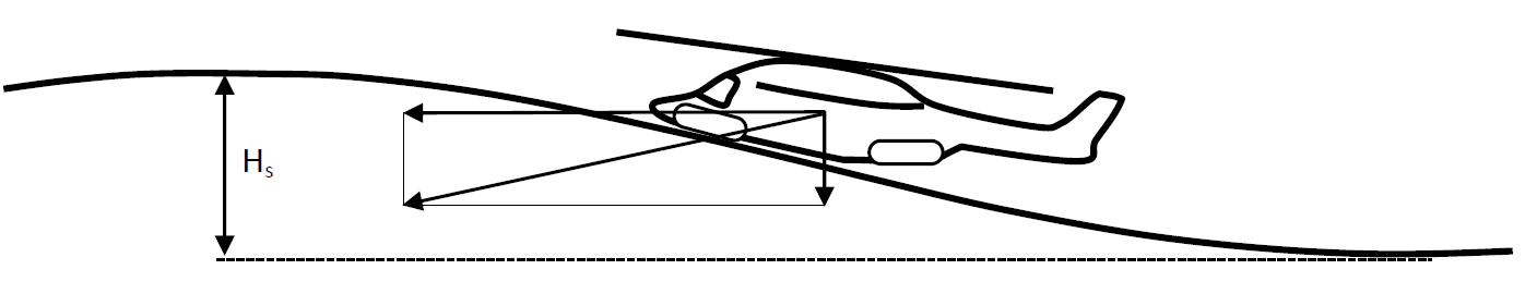
a) Water entry into wave
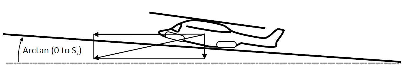
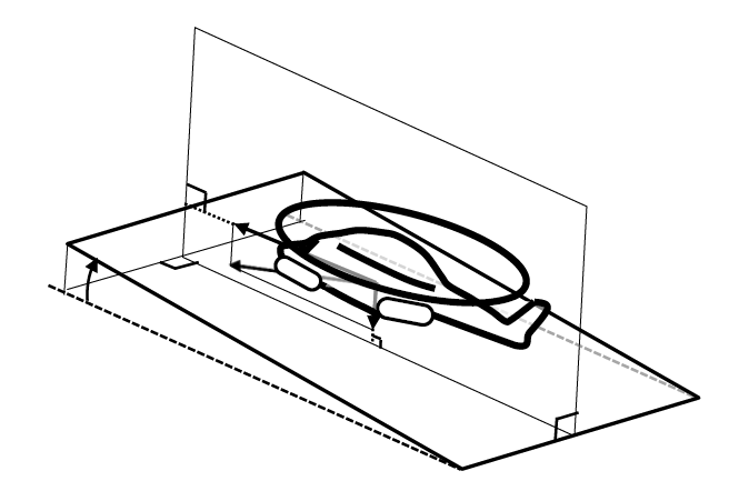
b) Water entry into inclined plane of stationary water, steepness range - zero to significant steepness (Ss)
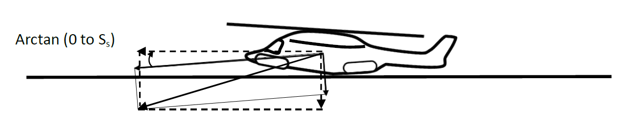
c) Water entry into a stationary horizontal water surface using an equivalent water entry angle and velocity relative to the water surface
(Dashed arrows show required horizontal and vertical speeds)
Figure 1 – Illustration of water entry test or simulation conditions which may be considered for structural provisions assessment.
[Amdt No: 29/5]
FATIGUE EVALUATION
CS 29.571 Fatigue Tolerance Evaluation of Metallic Structure
ED Decision 2012/022/R
(a)A fatigue tolerance evaluation of each Principal Structural Element (PSE) must be performed, and appropriate inspections and retirement time or approved equivalent means must be established to avoid Catastrophic Failure during the operational life of the rotorcraft.
(b)Reserved
(c)Reserved
(d)Each PSE must be identified. Structure to be considered must include the rotors, rotor drive systems between the engines and rotor hubs, controls, fuselage, fixed and movable control surfaces, engine and transmission mountings, landing gear, and their related primary attachments.
(e)Each fatigue tolerance evaluation must include:
(1)In-flight measurements to determine the fatigue loads or stresses for the PSEs identified in sub-paragraph (d) in all critical conditions throughout the range of design limitations required in CS 29.309 (including altitude effects), except that manoeuvring load factors need not exceed the maximum values expected in operations.
(2)The loading spectra as severe as those expected in operations based on loads or stresses determined under sub-paragraph (e)(1), including external load operations, if applicable, and other high frequency power-cycle operations.
(3)Take-off, landing, and taxi loads when evaluating the landing gear (including skis and floats) and other affected PSEs.
(4)For each PSE identified in sub-paragraph (d), a threat assessment, which includes a determination of the probable locations, types, and sizes of damage taking into account fatigue, environmental effects, intrinsic and discrete flaws, or accidental damage that may occur during manufacture or operation.
(5)A determination of the fatigue tolerance characteristics for the PSE with the damage identified in sub-paragraph (e)(4) that supports the inspection and retirement times, or other approved equivalent means.
(6)Analyses supported by test evidence and, if available, service experience.
(f)A residual strength determination is required that substantiates the maximum damage size assumed in the fatigue tolerance evaluation. In determining inspection intervals based on damage growth, the residual strength evaluation must show that the remaining structure, after damage growth, is able to withstand design limit loads without failure.
(g)The effect of damage on stiffness, dynamic behaviour, loads and functional performance must be considered.
(h)The inspection and retirement times or approved equivalent means established under this paragraph must be included in the Airworthiness Limitation Section of the Instructions for Continued Airworthiness required by CS 29.1529 and paragraph A29.4 of Appendix A.
(i)If inspections for any of the damage types identified in sub-paragraph (e)(4) cannot be established within the limitations of geometry, inspectability, or good design practice, then supplemental procedures, in conjunction with the PSE retirement time, must be established to minimize the risk of occurrence of these types of damage that could result in a catastrophic failure during the operational life of the rotorcraft.
[Amdt 29/3]
AMC1 29.571 Fatigue tolerance evaluation of metallic structure
ED Decision 2023/001/R
ROLLING CONTACT FATIGUE
This AMC supplements FAA AC 29-2C, § AC 29.571 and should be used in conjunction with that AC when demonstrating compliance with CS 29.571.
(a)Definitions
(1)Rolling contact fatigue (RCF): a form of fatigue that occurs due to the cyclic strains arising from the loading present during rolling contact between two parts of an assembly, e.g. a bearing race and a rolling element.
Note: For the purposes of this AMC, RCF also includes combinations of rolling and sliding contact phenomena.
(2)Integral race: a bearing race that is an integral part of the transmission structural component such as a gear or shaft.
(b)Explanation
Service experience has shown that RCF can initiate on the surface and below the surface in contact areas of structural elements (typically, but not limited to, bearing races and rolling elements and gear teeth) that, in some cases, can propagate to a failure with catastrophic results. It is often assumed that RCF leads first to non-critical partial failures such as micro-pitting and spalling that will be detected before more severe failure modes can develop, such as a complete crack through a part. However, experience has shown that, in some cases, critical failure modes can develop shortly after the occurrence of non-critical partial failures. In such cases, analyses and tests are necessary to demonstrate that sufficient time is available, and the performance of the detection system is adequate to ensure the timely detection to prevent a catastrophic failure.
The certification specifications in CS 29.571 require the identification and fatigue tolerance evaluation of principal structural elements (PSEs), leading to the establishment of inspection and retirement time or approved equivalent means to avoid a catastrophic failure during the operational life of the rotorcraft. In order to complete this evaluation, the impact of threats such as environmental effects, flaws and damages should be considered.
However, specific characteristics of parts submitted to RCF (e.g. bearings and gears), such as the difficulty to visually inspect the operating nature of these elements, which can lead to mechanical degradation and the impact of RCF, make the application of some of the methods challenging.
The procedures of this AMC are intended to help ensure that the effects of RCF are accounted for in the fatigue tolerance evaluations required by CS 29.571.
(c)Procedure
The fatigue tolerance evaluation of PSEs should include, when applicable, the effect of RCF considering:
damage threats such as dents, scratches, corrosion, loss of pre-load in bearings or joints, surface and sub-surface material defects;
residual stress coming from surface treatments and other manufacturing processes and all other applicable loading conditions.
For this purpose, steps should be taken to minimise the risk of crack initiation due to RCF on PSEs (and in particular for integrated bearing races), by minimising contact pressures, specifying high standards for surface finishes, ensuring good lubrication, guaranteeing cleanliness and maintaining lubricant quality regardless of the fatigue tolerance approach selected. The applicant should verify that the selected allowables are suitable to ensure the integrity of the affected components in the operating conditions (temperature, lubrication, cleanliness, etc.) applicable to their design. Experience has demonstrated that it can be beneficial for bearings to be designed so that the reliability of any integrated race subject to the fatigue tolerance evaluation is even higher than the less critical race of the bearing. In this way, degradation of the less critical race can lead to detection of the bearing failure before cracking initiates in the integrated race. The consequences of damage to the integrated race from the debris generated in such scenarios should be considered in the evaluation.
As it is difficult to totally preclude cracking initiated by RCF, a fail-safe approach is recommended wherever possible, such that cracking of the affected structural element(s) is detected prior to its residual strength capability falling below the required levels prescribed in CS 29.571(f). Should fatigue cracks initiate and develop into:
(1)Partial failure, such as spalling: the applicant should demonstrate that this condition will be detected at an early stage to avoid a catastrophic failure due to further fatigue failure, or loss of integrity of the affected part or any surrounding ones. Any assumptions regarding potential surface and sub-surface cracking considering possible damages or flaws, and whether a through crack may develop and its relationship with other forms of damage including spalling should be verified.
(2)Failure, such as through-cracking of a part together with any other associated damage in the system: the applicant should demonstrate that the remaining structure will withstand service loads and design limit loads without failure until the failure is detected and damaged components are repaired or replaced to avoid a catastrophic failure. Any assumptions regarding crack path development (i.e. bifurcation, multicracks, etc.) that could affect this fail-safe demonstration should be verified.
This demonstration should be performed as appropriate using experience from similar designs, functional tests, structural tests and/or reliable analyses to substantiate that the fail-safe design objective has been achieved, including residual strength demonstration. In addition, the continued safe operation of the affected mechanical system(s) should be ensured for this period considering the potential effect of the failure or partial failure taking into account any pre-existing fatigue damage accrued prior to the failure in the affected component and/or surrounding ones on stiffness, dynamic behaviour, loads and functional performance.
The effectiveness and reliability of means of crack detection for the fail-safe approach, including indirect means of detection such as chip detection systems, and associated instructions for continued airworthiness should be evaluated to show that, if implemented as required, they will result in timely detection and repair or replacement of damaged components. Furthermore, the instructions for continued airworthiness, prescribing the maintenance actions leading up to and following detection of potential failure or partial failure should be substantiated sufficiently to ensure timely repair or replacement of damaged components. The substantiation should consider aspects such as threshold criteria on indicators of means of detection for additional investigative actions and removal from service of the damaged parts, the overall clarity and practicality of the instructions for continued airworthiness and human factors aspects.
In addition to following a fail-safe approach, inspection and retirement times may be needed in order to ensure that the assumptions supporting the fail-safety and detection of failure remain valid throughout the operational life of the component.
[Amdt No: 29/11]
CS 29.573 Damage Tolerance and Fatigue Evaluation of Composite Rotorcraft Structures
ED Decision 2012/022/R
(a) Composite rotorcraft structure must be evaluated under the damage tolerance requirements of sub-paragraph (d) unless the applicant establishes that a damage tolerance evaluation is impractical within the limits of geometry, inspectability, and good design practice. In such a case, the composite rotorcraft structure must undergo a fatigue evaluation in accordance with sub-paragraph (e)
(b)Reserved
(c)Reserved
(d)Damage Tolerance Evaluation:
(1)Damage tolerance evaluations of composite structures must show that Catastrophic Failure due to static and fatigue loads is avoided throughout the operational life or prescribed inspection intervals of the rotorcraft.
(2)The damage tolerance evaluation must include PSEs of the airframe, main and tail rotor drive systems, main and tail rotor blades and hubs, rotor controls, fixed and movable control surfaces, engine and transmission mountings, landing gear, and any other detail design points or parts whose failure or detachment could prevent continued safe flight and landing.
(3)Each damage tolerance evaluation must include:
(i)The identification of the structure being evaluated;
(ii)A determination of the structural loads or stresses for all critical conditions throughout the range of limits in CS 29.309 (including altitude effects), supported by in-flight and ground measurements, except that manoeuvring load factors need not exceed the maximum values expected in service;
(iii)The loading spectra as severe as those expected in service based on loads or stresses determined under sub-paragraph (d)(3)(ii), including external load operations, if applicable, and other operations including high torque events;
(iv)A Threat Assessment for all structure being evaluated that specifies the locations, types, and sizes of damage, considering fatigue, environmental effects, intrinsic and discrete flaws, and impact or other accidental damage (including the discrete source of the accidental damage) that may occur during manufacture or operation;
(v)An assessment of the residual strength and fatigue characteristics of all structure being evaluated that supports the replacement times and inspection intervals established under sub-paragraph (d)(4); and
(vi)allowances for the detrimental effects of material, fabrication techniques, and process variability.
(4)Replacement times, inspections, or other procedures must be established to require the repair or replacement of damaged parts to prevent Catastrophic Failure. These replacement times, inspections, or other procedures must be included in the Airworthiness Limitations Section of the Instructions for Continued Airworthiness required by CS 29.1529.
(i)Replacement times must be determined by tests, or by analysis supported by tests to show that throughout its life the structure is able to withstand the repeated loads of variable magnitude expected in-service. In establishing these replacement times, the following items must be considered:
(A)Damage identified in the Threat Assessment required by sub-paragraph (d)(3)(iv);
(B)Maximum acceptable manufacturing defects and in-service damage (i.e., those that do not lower the residual strength below ultimate design loads and those that can be repaired to restore ultimate strength); and
(C)Ultimate load strength capability after applying repeated loads.
(ii)Inspection intervals must be established to reveal any damage identified in the Threat Assessment required by sub-paragraph (d)(3)(iv) that may occur from fatigue or other in-service causes before such damage has grown to the extent that the component cannot sustain the required residual strength capability. In establishing these inspection intervals, the following items must be considered:
(A)The growth rate, including no-growth, of the damage under the repeated loads expected in-service determined by tests or analysis supported by tests; and
(B)The required residual strength for the assumed damage established after considering the damage type, inspection interval, detectability of damage, and the techniques adopted for damage detection. The minimum required residual strength is limit load.
(5)The effects of damage on stiffness, dynamic behaviour, loads and functional performance must be taken into account when substantiating the maximum assumed damage size and inspection interval.
(e)Fatigue Evaluation:
If an applicant establishes that the damage tolerance evaluation described in sub- paragraph (d) is impractical within the limits of geometry, inspectability, or good design practice, the applicant must do a fatigue evaluation of the particular composite rotorcraft structure and:
(1)Identify structure considered in the fatigue evaluation;
(2)Identify the types of damage considered in the fatigue evaluation;
(3)Establish supplemental procedures to minimise the risk of Catastrophic Failure associated with damage identified in sub-paragraph (e)(2); and
(4)Include these supplemental procedures in the Airworthiness Limitations section of the Instructions for Continued Airworthiness required by CS 29.1529.
[Amdt 29/3]