
Filters
Subpart D — Design and Construction
GENERAL
CS 29.601 Design
ED Decision 2003/16/RM
(a)The rotorcraft may have no design features or details that experience has shown to be hazardous or unreliable.
(b)The suitability of each questionable design detail and part must be established by tests.
CS 29.602 Critical parts
ED Decision 2003/16/RM
(a)Critical part - A critical part is a part, the failure of which could have a catastrophic effect upon the rotorcraft, and for which critical characteristics have been identified which must be controlled to ensure the required level of integrity.
(b)If the type design includes critical parts, a critical parts list shall be established. Procedures shall be established to define the critical design characteristics, identify processes that affect those characteristics, and identify the design change and process change controls necessary for showing compliance with the quality assurance requirements of Part-21.
CS 29.603 Materials
ED Decision 2003/16/RM
The suitability and durability of materials used for parts, the failure of which could adversely affect safety, must –
(a)Be established on the basis of experience or tests;
(b)Meet approved specifications that ensure their having the strength and other properties assumed in the design data; and
(c)Take into account the effects of environmental conditions, such as temperature and humidity, expected in service.
CS 29.605 Fabrication methods
ED Decision 2003/16/RM
(a)The methods of fabrication used must produce consistently sound structures. If a fabrication process (such as gluing, spot welding, or heat- treating) requires close control to reach this objective, the process must be performed according to an approved process specification.
(b)Each new aircraft fabrication method must be substantiated by a test program.
CS 29.607 Fasteners
ED Decision 2003/16/RM
(a)Each removable bolt, screw, nut, pin or other fastener whose loss could jeopardise the safe operation of the rotorcraft must incorporate two separate locking devices. The fastener and its locking devices may not be adversely affected by the environmental conditions associated with the particular installation.
(b)No self-locking nut may be used on any bolt subject to rotation in operation unless a non-friction locking device is used in addition to the self-locking device.
AMC1 29.607 Fasteners
ED Decision 2023/001/R
This AMC supplements FAA AC 29-2C, § AC 29.607 and should be used in conjunction with that AC when demonstrating compliance with CS 29.601, CS 29.602, CS 29.603 and CS 29.607.
(a)Explanation
Designers should consistently take into account the limitations of the standards, including the applicable fastener manufacturing processes and quality controls, to ensure that when a standard part or qualified standard part is selected, its properties and associated level of reliability will meet the applicable certification requirements for the design.
The intent of this AMC is to give further guidance to the design approval holders (DAHs) and applicants for design approvals to help ensure that appropriate measures are considered for initial certification, including associated continued airworthiness aspects, to minimise the risk that the use of standard fasteners might compromise the intended level of safety.
(b)Definitions
(1)Standard fastener: a fastener that is a standard part. Fasteners (nuts and bolts) being produced according to a certain standard which is not directly approved by the Agency. They fall within the category of standard parts as defined in point 21.A.303(c) of Annex I (Part 21) to Commission Regulation (EU) No 748/2012.
(2)Qualified standard fastener: a standard fastener that requires additional verification of compliance with specification and/or control of their source, by methods defined by the DAH.
(3)Critical installation: a structural/mechanical assembly which may include fasteners the failure of which (single or multiple due to common cause) is classified as hazardous or catastrophic.
(c)Procedures
Failures of standard fasteners may have severe consequences at the aircraft level when used in critical installations.
Once demonstrated, conformance to a standard provides a certain level of reliability under known loading and environmental conditions. The reliability of a standard part or any other part specified in the design needs to be assessed and shown to be compatible with the design objectives to be met. Designers should take care to ensure that they select appropriate fasteners to meet the certification objectives for continued function and reliability, taking into account the limitations of the applicable standards including the associated manufacturing processes and applicable quality controls.
This AMC is therefore addressed to DAHs, to provide them with guidance on appropriate actions to ensure appropriate utilisation of standard fasteners in their designs, to help them to instruct production organisations and maintenance organisations as necessary to ensure continued airworthiness, and to provide means by which unsafe conditions related to the use in design of standard fasteners can be prevented.
In order to reduce the risk of critical installations failing, through the inadvertent use of defective standard fasteners or due to the inappropriate selection of standards, the Agency recommends that all applicants for type certificates and design changes perform a design review to ensure that the risk posed by the use of standard parts is mitigated by:
(1)ensuring that fasteners (nuts and bolts) used in the design will meet the certification requirements, taking into account any limitations of the selected standards, the associated fastener manufacturing processes and quality controls, and relevant service experience;
[Note: The degree to which the standard ensures relevant characteristics such as locking functions, static strength and fatigue strength should be evaluated as far as is necessary based on the criticality of the intended use and operating environment of the parts. Consideration should be given to stress levels arising from manufacture, installation requirements, external loading and temperature effects. Particular attention should be paid to standard parts that utilise high-strength alloys in combination with plating or other processes that may increase the risk of hydrogen embrittlement or deformation processes that are not closely specified.]
(2)ensuring that the design standard met and associated procedures followed for the production of the aircraft are maintained throughout the operational life of the aircraft, e.g. through the use of the ICA controlling maintenance of critical installations;
(3)creating, when standard fasteners (nuts and bolts) are selected, a list of critical installations where only qualified standard fasteners (nuts and bolts) may be used. Redundancy of fasteners alone may not negate the need to qualify the fasteners as all the fasteners on a joint could originate from a common defective batch. Similarly, required double locking functions on fasteners may also need consideration of qualified standard fasteners to ensure that the fail-safe design philosophy is maintained when common cause failure of both locking functions is possible;
(4)defining how the standard fastener is qualified wherever necessary;
(5)clearly defining any necessary additional conformity checks as part of the type design standard, specifying requirements for approved suppliers and any other criteria necessary for acceptance, storage and installation of standard fasteners that are appropriate for use in the design;
(6)ensuring through maintenance instructions that qualified standard fasteners are only replaced by other qualified standard fasteners; and
(7)considering introducing a DAH part numbering system for qualified standard fasteners, at which point they would become aviation parts. (Note: If such part numbering is implemented and further part marking is not feasible due to the part’s size or for other reasons, other means such as regular appropriate batch controls should be established, and documentation provided according to point 21.A.804(b) of Part 21.)
In addition, DAHs are reminded that certain existing Certification Specifications and regulations specifically address critical parts. Typically standard parts are not appropriate for use as critical parts. All critical parts are subject to a critical parts plan that controls their critical characteristics during production and service.
[Amdt No: 29/11]
CS 29.609 Protection of structure
ED Decision 2003/16/RM
Each part of the structure must:
(a)Be suitably protected against deterioration or loss of strength in service due to any cause, including:
(1)Weathering;
(2)Corrosion; and
(3)Abrasion; and
(b)Have provisions for ventilation and drainage where necessary to prevent the accumulation of corrosive, flammable, or noxious fluids.
CS 29.610 Lightning and static electricity protection
ED Decision 2016/025/R
(a)The rotorcraft structure must be protected against catastrophic effects from lightning.
(b)For metallic components, compliance with sub-paragraph (a) may be shown by:
(1)Electrically bonding the components properly to the airframe; or
(2)Designing the components so that a strike will not endanger the rotorcraft.
(c)For non-metallic components, compliance with sub-paragraph (a) may be shown by:
(1)Designing the components to minimise the effect of a strike; or
(2)Incorporating acceptable means of diverting the resulting electrical current to not endanger the rotorcraft.
(d)The electrical bonding and protection against lightning and static electricity must:
(1)Minimise the accumulation of electrostatic charge;
(2)Minimise the risk of electrical shock to crew, passengers, and servicing and maintenance personnel using normal precautions;
(3)Provide an electrical return path, under both normal and fault conditions, on rotorcraft having grounded electrical systems; and
(4)Reduce to an acceptable level the effects of static electricity on the functioning of essential electrical and electronic equipment.
[Amdt 29/4]
AMC1 29.610 Lightning and static electricity protection
ED Decision 2023/001/R
(a)Purpose
This AMC provides an acceptable means of compliance for rotorcraft components evaluation after lightning strike.
(b)Related Certification Specifications
CS 29.610 ‘Lightning and static electricity protection’
CS 29.571 ‘Fatigue tolerance evaluation of metallic structure’
CS 29.573 ‘Damage tolerance and fatigue evaluation of composite structures’
CS 29.1529 ‘Instructions for Continued Airworthiness’
(c)Explanation
CS 29.610 requires the protection of rotorcraft structural components, propulsion system, gearboxes, mechanical and hydraulic control systems from lightning damage that could result in catastrophic failures.
However, damage, failure or departure of any rotorcraft component which could endanger the rotorcraft or its occupants must be part of the evaluation.
This AMC provides detailed guidance on damage tolerance evaluation, including residual strength criteria after lightning strike to ensure continuous safe flight and landing.
Each part, the failure of which implies potential catastrophic consequences and that is exposed to damage under lightning conditions, should be subject to further evaluation which includes:
(1)the nature and extent of the lightning damage (threat assessment, damage detectability, etc.);
(2)the demonstration of the functionality of the affected part up to detection;
(3)a static residual strength capability demonstration supported by analysis and/or test;
(4)when found necessary, a fatigue evaluation of a part with lightning damage for the demonstration of the exposure time before detection.
The airworthiness instruction requested after lightning strike (flight manual and maintenance instructions, etc.) should be consistent with the functional, static and fatigue evaluation of the damage consequences (considered to be a partial failure).
A similar approach should be considered for non-metallic components (for composite, see the AMC 20-29 (11c) guidance).
The above approach is also considered to be applicable for parts departure which could preclude continued safe flight and landing.
For non-structural components (e.g. radomes, panels), only static residual strength is requested for part detachment which could preclude continued safe flight and landing.
[Amdt No: 29/11]
CS 29.611 Inspection provisions
ED Decision 2003/16/RM
There must be means to allow close examination of each part that requires:
(a)Recurring inspection;
(b)Adjustment for proper alignment and functioning; or
(c)Lubrication.
CS 29.613 Material strength properties and design values
ED Decision 2003/16/RM
(a)Material strength properties must be based on enough tests of material meeting specifications to establish design values on a statistical basis.
(b)Design values must be chosen to minimise the probability of structural failure due to material variability. Except as provided in subparagraphs (d) and (e), compliance with this paragraph must be shown by selecting design values that assure material strength with the following probability:
(1)Where applied loads are eventually distributed through a single member within an assembly, the failure of which would result in loss of structural integrity of the component, 99% probability with 95% confidence; and
(2)For redundant structures, those in which the failure of individual elements would result in applied loads being safely distributed to other load-carrying members, 90% probability with 95% confidence.
(c)The strength, detail design, and fabrication of the structure must minimise the probability of disastrous fatigue failure, particularly at points of stress concentration.
(d)Material specifications must be those contained in documents accepted by the Agency.
(e)Other design values may be used if a selection of the material is made in which a specimen of each individual item is tested before use and it is determined that the actual strength properties of that particular item will equal or exceed those used in design.
AMC1 29.613 Material strength properties and design values
ED Decision 2023/001/R
COMPOSITE SANDWICH PANEL
(a)Qualification of the manufacturing process
The conditions outlined in the guidance standard AC 21-26, ‘Quality Control for the Manufacture of Composite Materials’ are considered to be relevant to composite sandwich PSE structure.
The qualification is intended to demonstrate that the combination of material, tooling, equipment, procedures, and other controls, making up the process, will produce representative parts having consistent material properties that conform to design requirements.
As part of the process qualification, destructive and non-destructive inspection (NDI) should be conducted to determine conformity to specified design requirements and check the suitability of the resulting product by assessing features such as:
uniformity of the adhesive fillets between honeycomb core cell wall and skin; in particular, the process should ensure that on both faces of the honeycomb core a regularly shaped fillet (meniscus) be established;
absence of ‘telegraphing’ effects and waviness on the skins of the sandwich panel;
distortion of the core cells — this defect could be particularly critical for highly curved panels unless suitable precautions are taken during fabrication (e.g. core thermal preforming);
presence in the adhesive of unacceptable levels of porosity or humidity;
disbonds between core and cells; and
weak bonds.
(b)Material strength and determination of design allowables
The strength properties of the sandwich panels should be established in order to ensure that the probability of structural failure due to material and process variability is minimised.
Because of the peculiarity of the sandwich panel construction, the material properties should be established on a specimen that is fully representative of the panel construction in terms of skin, core material and curing cycle.
Design features such as transition zones from solid laminate to core/skin should be also tested with a representative specimen for determination of strength properties.
It is expected that at least the following static allowables be established according to the statistics required in CS 29.613:
Adhesive shear strength;
Shear core strength (ribbon and transverse direction);
Core compression strength;
Flatwise strength;
Flexural strength;
Compressive strength; and
Bearing strength (for a specimen representative of all the panel areas where fasteners are installed and subject to significant bearing stresses).
In determining the above properties, the effect due to humidity uptake, highest and lowest temperature expected in service, manufacturing defects up to limit of acceptability and allowable in-service damage defined in maintenance documents, if any, should be considered. For PSEs, impact damages should also be assessed in accordance with CS 29.573.
The validity of the engineering formula used to establish analytical design allowables should be always verified by dedicated experimental activity in order to assess the effects of the manufacturing process (e.g. curing pressure which is normally limited to the crush core strength) and environmental conditions on the allowables predicted by these formulas.
(c)Damage tolerance and residual strength
(1)Threat survey and damage modes
Further to good processing, and when meeting the damage tolerance and fatigue evaluation of composite rotorcraft structures requirements of CS 29.573, the applicant should clearly demonstrate that a robust structure has been produced by showing that:
—a thorough damage threat survey has been completed which identifies and defines all threats, including impacts, heat, moisture, etc. and the potential for interaction of these threats is addressed;
—all damage modes have been identified for the configuration when subject to all likely threats, paying particular attention to all likely damage modes which might not be readily detected.
—For impact threats, this requires testing throughout the threat impact energy ranges up to a readily detectable damage using a range of appropriate impactor geometries, including blunt impactors up to 4 inches diameter(1), and a range of impactor stiffnesses, e.g. for hail threat damage (if appropriate), such that all competing damage modes can be identified. Representative boundary conditions should be used in the substantiating test campaigns; and
—all potentially undetectable damage modes (not only disbonds and weak bonds) have been simulated in testing (up to appropriate dimensions such that detection becomes possible, and the dimension of such damage has been quantified such that ultimate load (UL) can be maintained up to this level). The possibility of interaction between threats, e.g. impact and heat, should be considered in the simulation and substantiation process.
Note: Witness structures can be used in service, provided that a consistent and conservative correlation can be demonstrated to exist between the witness indications on the witness structure and the damage (all likely modes and extents) considered in the critical structure.
The recommendations for threat assessment and blunt impact evaluation are also addressed in AC 29.573.
(1) An alternative impactor diameter may be proposed by the applicant, based on the results of the damage threat survey.
(2)Residual strength after extensive damage or degradation
The part should be sized to sustain the required residual strength, in accordance with CS 29.573(d)(4)(ii)(B), with extensive damage or degradation of the most critical skin to core bond between available arrestment features. Such damage or degradation should be readily detectable to assure damage tolerance for bond failures which experience has shown not to be extremely improbable.
It is also expected that relevant fatigue testing at specimen level, representative of a design point (e.g. fastened joint) and typical panel configuration, be performed in order to assess the effects on the fatigue strength of:
—material/manufacturing process variability;
—environmental condition;
—allowables manufacturing defects; and
—impact damages.
(d)Instructions for Continued Airworthiness (ICA)
The ICA include clear instructions to inspect(2) (and repair), both internally and externally:
all load paths, e.g. up to load transfer fittings, joints, and other significant changes in stiffness and section, for damage following an overload event, e.g. impact, heavy landing, excessive gust, etc.;
all structure regularly exposed to extreme temperatures, e.g. local to engine outlets for aircraft used extensively in hot climates, etc. Although inspections intervals should have been justified according to the level of detectability and residual strength capability during certification substantiation based upon a damage threat survey, experience has indicated that the potential for interaction between heat and damage can be problematic.
(2) paying particular attention to:
repaired structures; and
any existing, and potentially related, ICA, e.g. existing ADs, etc.
[Amdt No: 29/11]
CS 29.619 Special factors
ED Decision 2003/16/RM
(a)The special factors prescribed in CS 29.621 to 29.625 apply to each part of the structure whose strength is:
(1)Uncertain;
(2)Likely to deteriorate in service before normal replacement; or
(3)Subject to appreciable variability due to:
(i)Uncertainties in manufacturing processes; or
(ii)Uncertainties in inspection methods.
(b)For each part of the rotorcraft to which CS 29.621 to 29.625 apply, the factor of safety prescribed in CS 29.303 must be multiplied by a special factor equal to:
(1)The applicable special factors prescribed in CS 29.621 to 29.625; or
(2)Any other factor great enough to ensure that the probability of the part being under strength because of the uncertainties specified in sub-paragraph (a) is extremely remote.
CS 29.621 Casting factors
ED Decision 2003/16/RM
(a)General. The factors, tests, and inspections specified in sub-paragraphs (b) and (c) must be applied in addition to those necessary to establish foundry quality control. The inspections must meet approved specifications. Subparagraphs (c) and (d) apply to structural castings except castings that are pressure tested as parts of hydraulic or other fluid systems and do not support structural loads.
(b)Bearing stressed and surfaces. The casting factors specified in sub-paragraphs (c) and (d):
(1)Need not exceed 1.25 with respect to bearing stresses regardless of the method of inspection used; and
(2)Need not be used with respect to the bearing surfaces of a part whose bearing factor is larger than the applicable casting factor.
(c)Critical castings. For each casting whose failure would preclude continued safe flight and landing of the rotorcraft or result in serious injury to any occupant, the following apply:
(1)Each critical casting must:
(i)Have a casting factor of not less than 1.25; and
(ii)Receive 100% inspection by visual, radiographic, and magnetic particle (for ferro-magnetic materials) or penetrant (for non ferromagnetic materials) inspection methods or approved equivalent inspection methods.
(2)For each critical casting with a casting factor less than 1.50, three sample castings must be static tested and shown to meet:
(i)The strength requirements of CS 29.305 at an ultimate load corresponding to a casting factor of 1.25; and
(ii)The deformation requirements of CS 29.305 at a load of 1.15 times the limit load.
(d)Non critical castings. For each casting other than those specified in sub-paragraph (c), the following apply:
(1)Except as provided in sub-paragraphs (d)(2) and (3), the casting factors and corresponding inspections must meet the following table:
Casting factor | Inspection |
2.0 or greater …….. | 100% visual. |
Less than 2.0 greater than 1.5 | 100% visual, and magnetic particle (ferromagnetic materials), penetrant (non ferro-magnetic materials), or approved equivalent inspection methods. |
1.25 through 1.50...... | 100% visual, and magnetic particle (ferromagnetic materials), penetrant (non ferro-magnetic materials), and radiographic or approved equivalent inspection methods. |
(2)The percentage of castings inspected by non visual methods may be reduced below that specified in sub-paragraph (d)(1) when an approved quality control procedure is established.
(3)For castings procured to a specification that guarantees the mechanical properties of the material in the casting and provides for demonstration of these properties by test of coupons cut from the castings on a sampling basis:
(i)A casting factor of 1.0 may be used; and
(ii)The castings must be inspected as provided in sub-paragraph (d)(1) for casting factors of ‘1.25 to 1.50’ and tested under sub-paragraph (c)(2).
CS 29.623 Bearing factors
ED Decision 2003/16/RM
(a)Except as provided in sub-paragraph (b), each part that has clearance (free fit), and that is subject to pounding or vibration, must have a bearing factor large enough to provide for the effects of normal relative motion.
(b)No bearing factor need be used on a part for which any larger special factor is prescribed.
CS 29.625 Fitting factors
ED Decision 2003/16/RM
For each fitting (part or terminal used to join one structural member to another) the following apply:
(a)For each fitting whose strength is not proven by limit and ultimate load tests in which actual stress conditions are simulated in the fitting and surrounding structures, a fitting factor of at least 1.15 must be applied to each part of:
(1)The fitting;
(2)The means of attachment; and
(3)The bearing on the joined members.
(b)No fitting factor need be used:
(1)For joints made under approved practices and based on comprehensive test data (such as continuous joints in metal plating, welded joints, and scarf joints in wood); and
(2)With respect to any bearing surface for which a larger special factor is used.
(c)For each integral fitting, the part must be treated as a fitting up to the point at which the section properties become typical of the member.
(d)Each seat, berth, litter, safety belt, and harness attachment to the structure must be shown by analysis, tests, or both, to be able to withstand the inertia forces prescribed in CS 29.561(b)(3) multiplied by a fitting factor of 1.33.
CS 29.629 Flutter and divergence
ED Decision 2003/16/RM
Each aerodynamic surface of the rotorcraft must be free from flutter and divergence under each appropriate speed and power condition.
CS 29.631 Bird strike
ED Decision 2021/016/R
(See AMC1 29.631)
The rotorcraft must be designed to ensure a continued safe flight and landing (for Category A) or a safe landing (for Category B) after a strike with a 1.0-kg (2.2-lb) bird when the velocity of the rotorcraft relative to the bird along the flight path of the rotorcraft is equal to VNE or VH ‘True Airspeed’ (TAS), whichever is less, at altitudes up to 2 438 m (8 000 ft). The applicant must demonstrate compliance through tests, or analysis based on tests that are carried out on sufficiently representative structures of similar design.
[Amdt No: 29/10]
AMC1 29.631 Bird strike
ED Decision 2021/016/R
This AMC supersedes AC 29.631 of Federal Aviation Administration (FAA) Advisory Circular (AC) 29 2C. The applicant should consider this AMC to demonstrate compliance with CS 29.631.
(a)To demonstrate the remaining capability of the rotorcraft after a single bird strike, the applicant should evaluate the following parts of the rotorcraft:
(1)the windshield directly in front of the occupants and its supporting frame, which should be capable of withstanding a bird strike without penetration; and
(2)other exposed structures, systems, and equipment, particularly flight control surfaces (including the main and tail rotors) and any exposed flight control system components.
(i)The applicant should make a final selection of the areas to be evaluated based on a comprehensive hazard analysis of the following:
(A)the damage to the structures, equipment, or systems that are exposed to the trajectory of the bird, based on conservative assumptions; and
(B)the criticalities of those exposed items and their capability to ensure a continued safe flight and landing (for Category A) or a safe landing (for Category B).
(ii)When performing the hazard analysis, the applicant should consider the following effects of a bird strike:
(A)direct effects to ensure the integrity of the structures and the functionality of the systems or equipment (also considering shock loads) that are critical for a continued safe flight and landing (for Category A) or a safe landing (for Category B), as applicable; and
(B)induced effects to examine the possible consequences of pieces ejected from the structures, systems, or equipment that are struck by a bird on other structures, systems, and equipment.
Note: the capability to withstand multiple bird strikes is only evaluated for engines as specified under CS-E 800 ‘Bird Strike and Ingestion’.
(b)For the demonstration under point (a), the altitude range within which the velocity VH is evaluated should be defined and should not exceed 2 438 m (8 000 ft).
[Amdt No: 29/10]
ROTORS
CS 29.653 Pressure venting and drainage of rotor blades
ED Decision 2003/16/RM
(a)For each rotor blade:
(1)There must be means for venting the internal pressure of the blade;
(2)Drainage holes must be provided for the blade; and
(3)The blade must be designed to prevent water from becoming trapped in it.
(b)Sub-paragraphs (a)(1) and (2) do not apply to sealed rotor blades capable of withstanding the maximum pressure differentials expected in service.
CS 29.659 Mass balance
ED Decision 2003/16/RM
(a)The rotor and blades must be mass balanced as necessary to:
(1)Prevent excessive vibration; and
(2)Prevent flutter at any speed up to the maximum forward speed.
(b)The structural integrity of the mass balance installation must be substantiated.
CS 29.661 Rotor blade clearance
ED Decision 2003/16/RM
There must be enough clearance between the rotor blades and other parts of the structure to prevent the blades from striking any part of the structure during any operating condition.
CS 29.663 Ground resonance prevention means
ED Decision 2003/16/RM
(a)The reliability of the means for preventing ground resonance must be shown either by analysis and tests, or reliable service experience, or by showing through analysis or tests that malfunction or failure of a single means will not cause ground resonance.
(b)The probable range of variations, during service, of the damping action of the ground resonance prevention means must be established and must be investigated during the test required by CS 29.241.
CONTROL SYSTEMS
CS 29.671 General
ED Decision 2003/16/RM
(a)Each control and control system must operate with the ease, smoothness, and positiveness appropriate to its function.
(b)Each element of each flight control system must be designed, or distinctively and permanently marked, to minimise the probability of any incorrect assembly that could result in the malfunction of the system.
(c)A means must be provided to allow full control movement of all primary flight controls prior to flight, or a means must be provided that will allow the pilot to determine that full control authority is available prior to flight.
CS 29.672 Stability augmentation, automatic, and power-operated systems
ED Decision 2003/16/RM
If the functioning of stability augmentation or other automatic or power-operated system is necessary to show compliance with flight characteristics requirements of CS-29, the system must comply with CS 29.671 and the following:
(a)A warning which is clearly distinguishable to the pilot under expected flight conditions without requiring the pilot’s attention must be provided for any failure in the stability augmentation system or in any other automatic or power-operated system which could result in an unsafe condition if the pilot is unaware of the failure. Warning systems must not activate the control systems.
(b)The design of the stability augmentation system or of any other automatic or power-operated system must allow initial counteraction of failures without requiring exceptional pilot skill or strength, by overriding the failure by moving the flight controls in the normal sense, and by deactivating the failed system.
(c)It must be shown that after any single failure of the stability augmentation system or any other automatic or power-operated system:
(1)The rotorcraft is safely controllable when the failure or malfunction occurs at any speed or altitude within the approved operating limitations;
(2)The controllability and manoeuvrability requirements of CS-29 are met within a practical operational flight envelope (for example, speed, altitude, normal acceleration, and rotorcraft configurations) which is described in the rotorcraft flight manual; and
(3)The trim and stability characteristics are not impaired below a level needed to allow continued safe flight and landing.
CS 29.673 Primary flight controls
ED Decision 2003/16/RM
Primary flight controls are those used by the pilot for immediate control of pitch, roll, yaw, and vertical motion of the rotorcraft.
CS 29.674 Interconnected controls
ED Decision 2003/16/RM
Each primary flight control system must provide for safe flight and landing and operate independently after a malfunction, failure, or jam of any auxiliary interconnected control.
CS 29.675 Stops
ED Decision 2003/16/RM
(a)Each control system must have stops that positively limit the range of motion of the pilot’s controls.
(b)Each stop must be located in the system so that the range of travel of its control is not appreciably affected by:
(1)Wear;
(2)Slackness; or
(3)Take-up adjustments.
(c)Each stop must be able to withstand the loads corresponding to the design conditions for the system.
(d)For each main rotor blade:
(1)Stops that are appropriate to the blade design must be provided to limit travel of the blade about its hinge points; and
(2)There must be means to keep the blade from hitting the droop stops during any operation other than starting and stopping the rotor.
CS 29.679 Control system locks
ED Decision 2003/16/RM
If there is a device to lock the control system with the rotorcraft on the ground or water, there must be means to:
(a)Automatically disengage the lock when the pilot operates the controls in a normal manner, or limit the operation of the rotorcraft so as to give unmistakable warning to the pilot before take-off, and
(b)Prevent the lock from engaging in flight.
CS 29.681 Limit load static tests
ED Decision 2003/16/RM
(a)Compliance with the limit load requirements of this Code must be shown by tests in which:
(1)The direction of the test loads produces the most severe loading in the control system; and
(2)Each fitting, pulley, and bracket used in attaching the system to the main structure is included.
(b)Compliance must be shown (by analyses or individual load tests) with the special factor requirements for control system joints subject to angular motion.
CS 29.683 Operation tests
ED Decision 2003/16/RM
It must be shown by operation tests that, when the controls are operated from the pilot compartment with the control system loaded to correspond with loads specified for the system, the system is free from:
(a)Jamming;
(b)Excessive friction; and
(c)Excessive deflection.
CS 29.685 Control system details
ED Decision 2003/16/RM
(a)Each detail of each control system must be designed to prevent jamming, chafing, and interference from cargo, passengers, loose objects, or the freezing of moisture.
(b)There must be means in the cockpit to prevent the entry of foreign objects into places where they would jam the system.
(c)There must be means to prevent the slapping of cables or tubes against other parts.
(d)Cable systems must be designed as follows:
(1)Cables, cable fittings, turnbuckles, splices, and pulleys must be of an acceptable kind.
(2)The design of cable systems must prevent any hazardous change in cable tension throughout the range of travel under any operating conditions and temperature variations.
(3)No cable smaller than 3.2 mm (1/8 inch) diameter may be used in any primary control system.
(4)Pulley kinds and sizes must correspond to the cables with which they are used.
(5)Pulleys must have close fitting guards to prevent the cables from being displaced or fouled.
(6)Pulleys must lie close enough to the plane passing through the cable to prevent the cable from rubbing against the pulley flange.
(7)No fairlead may cause a change in cable direction of more than 3°.
(8)No clevis pin subject to load or motion and retained only by cotter pins may be used in the control system.
(9)Turnbuckles attached to parts having angular motion must be installed to prevent binding throughout the range of travel.
(10)There must be means for visual inspection at each fairlead, pulley, terminal, and turnbuckle.
(e)Control system joints subject to angular motion must incorporate the following special factors with respect to the ultimate bearing strength of the softest material used as a bearing:
(1)3.33 for push-pull systems other than ball and roller bearing systems.
(2)2.0 for cable systems.
(f)For control system joints, the manufacturer’s static, non-Brinell rating of ball and roller bearings may not be exceeded.
CS 29.687 Spring devices
ED Decision 2003/16/RM
(a)Each control system spring device whose failure could cause flutter or other unsafe characteristics must be reliable.
(b)Compliance with sub-paragraph (a) must be shown by tests simulating service conditions.
CS 29.691 Autorotation control mechanism
ED Decision 2003/16/RM
Each main rotor blade pitch control mechanism must allow rapid entry into autorotation after power failure.
CS 29.695 Power boost and power-operated control system
ED Decision 2003/16/RM
(a)If a power boost or power-operated control system is used, an alternate system must be immediately available that allows continued safe flight and landing in the event of –
(1)Any single failure in the power portion of the system; or
(2)The failure of all engines.
(b)Each alternate system may be a duplicate power portion or a manually operated mechanical system. The power portion includes the power source (such as hydraulic pumps), and such items as valves, lines, and actuators.
(c)The failure of mechanical parts (such as piston rods and links), and the jamming of power cylinders, must be considered unless they are extremely improbable.
LANDING GEAR
CS 29.723 Shock absorption tests
ED Decision 2003/16/RM
The landing inertia load factor and the reserve energy absorption capacity of the landing gear must be substantiated by the tests prescribed in CS 29.725 and 29.727, respectively. These tests must be conducted on the complete rotorcraft or on units consisting of wheel, tyre, and shock absorber in their proper relation.
CS 29.725 Limit drop test
ED Decision 2018/007/R
The limit drop test must be conducted as follows:
(a)The drop height must be at least 20 cm (8 inches).
(b)If considered, the rotor lift specified in CS 29.473(a) must be introduced into the drop test by appropriate energy absorbing devices or by the use of an effective mass.
(c)Each landing gear unit must be tested in the attitude simulating the landing condition that is most critical from the standpoint of the energy to be absorbed by it.
(d)When an effective mass is used in showing compliance with sub-paragraph (b), the following formulae may be used instead of more rational computations:
where:
We =the effective weight to be used in the drop test (N (lb)).
W = WM for main gear units (N (lb)), equal to the static reaction on the particular unit with the rotorcraft in the most critical attitude. A rational method may be used in computing a main gear static reaction, taking into consideration the moment arm between the main wheel reaction and the rotorcraft centre of gravity.
W = WN for nose gear units (N (lb)), equal to the vertical component of the static reaction that would exist at the nose wheel, assuming that the mass of the rotorcraft acts at the centre of gravity and exerts a force of 1.0 g downward and 0.25 g forward.
W = WT for tailwheel units (N (lb)) equal to whichever of the following is critical:
(1)The static weight on the tailwheel with the rotorcraft resting on all wheels; or
(2)The vertical component of the ground reaction that would occur at the tailwheel assuming that the mass of the rotorcraft acts at the centre of gravity and exerts a force of 1 g downward with the rotorcraft in the maximum nose-up attitude considered in the nose-up landing conditions.
h = specified free drop height (m (inches)).
L = ratio of assumed rotor lift to the rotorcraft weight.
d = deflection under impact of the tyre (at the proper inflation pressure) plus the vertical component of the axle travel (m (inches)) relative to the drop mass.
n = limit inertia load factor.
nj = the load factor developed, during impact, on the mass used in the drop test (i.e., the acceleration dv/dt in g recorded in the drop test plus 1.0).
[Amdt No: 29/5]
CS 29.727 Reserve energy absorption drop test
ED Decision 2003/16/RM
The reserve energy absorption drop test must be conducted as follows:
(a)The drop height must be 1.5 times that specified in CS 29.725(a).
(b)Rotor lift, where considered in a manner similar to that prescribed in CS 29.725(b), may not exceed 1.5 times the lift allowed under that paragraph.
(c)The landing gear must withstand this test without collapsing. Collapse of the landing gear occurs when a member of the nose, tail, or main gear will not support the rotorcraft in the proper attitude or allows the rotorcraft structure, other than landing gear and external accessories, to impact the landing surface.
CS 29.729 Retracting mechanism
ED Decision 2003/16/RM
For rotorcraft with retractable landing gear, the following apply:
(a)Loads. The landing gear, retracting mechanism, wheel well doors, and supporting structure must be designed for:
(1)The loads occurring in any manoeuvring condition with the gear retracted;
(2)The combined friction, inertia, and air loads occurring during retraction and extension at any airspeed up to the design maximum landing gear operating speed; and
(3)The flight loads, including those in yawed flight, occurring with the gear extended at any airspeed up to the design maximum landing gear extended speed.
(b)Landing gear lock. A positive means must be provided to keep the gear extended.
(c)Emergency operation. When other than manual power is used to operate the gear, emergency means must be provided for extending the gear in the event of:
(1)Any reasonably probable failure in the normal retraction system; or
(2)The failure of any single source of hydraulic, electric, or equivalent energy.
(d)Operation tests. The proper functioning of the retracting mechanism must be shown by operation tests.
(e)Position indicator. There must be means to indicate to the pilot when the gear is secured in the extreme positions.
(f)Control. The location and operation of the retraction control must meet the requirements of CS 29.777 and 29.779.
(g)Landing gear warning. An aural or equally effective landing gear warning device must be provided that functions continuously when the rotorcraft is in a normal landing mode and the landing gear is not fully extended and locked. A manual shutoff capability must be provided for the warning device and the warning system must automatically reset when the rotorcraft is no longer in the landing mode.
CS 29.731 Wheels
ED Decision 2003/16/RM
(a)Each landing gear wheel must be approved.
(b)The maximum static load rating of each wheel may not be less than the corresponding static ground reaction with:
(1)Maximum weight; and
(2)Critical centre of gravity.
(c)The maximum limit load rating of each wheel must equal or exceed the maximum radial limit load determined under the applicable ground load requirements of CS-29.
CS 29.733 Tyres
ED Decision 2003/16/RM
Each landing gear wheel must have a tyre:
(a)That is a proper fit on the rim of the wheel; and
(b)Of a rating that is not exceeded under:
(1)The design maximum weight;
(2)A load on each main wheel tyre equal to the static ground reaction corresponding to the critical centre of gravity; and
(3)A load on nose wheel tyres to be compared with the dynamic rating established for those tyres equal to the reaction obtained at the nose wheel, assuming that the mass of the rotorcraft acts as the most critical centre of gravity and exerts a force of 1.0 g downward and 0.25 g forward, the reactions being distributed to the nose and main wheels according to the principles of statics with the drag reaction at the ground applied only at wheels with brakes.
(c)Each tyre installed on a retractable landing gear system must, at the maximum size of the tyre type expected in service, have a clearance to surrounding structure and systems that is adequate to prevent contact between the tyre and any part of the structure or systems.
CS 29.735 Brakes
ED Decision 2003/16/RM
For rotorcraft with wheel-type landing gear, a braking device must be installed that is:
(a)Controllable by the pilot;
(b)Usable during power-off landings; and
(c)Adequate to:
(1)Counteract any normal unbalanced torque when starting or stopping the rotor; and
(2)Hold the rotorcraft parked on a 10° slope on a dry, smooth pavement.
CS 29.737 Skis
ED Decision 2003/16/RM
(a)The maximum limit load rating of each ski must equal or exceed the maximum limit load determined under the applicable ground load requirements of CS-29.
(b)There must be a stabilising means to maintain the ski in an appropriate position during flight. This means must have enough strength to withstand the maximum aerodynamic and inertia loads on the ski.
FLOATS AND HULLS
CS 29.751 Main float buoyancy
ED Decision 2003/16/RM
(a)For main floats, the buoyancy necessary to support the maximum weight of the rotorcraft in fresh water must be exceeded by:
(1)50%, for single floats; and
(2)60%, for multiple floats.
(b)Each main float must have enough watertight compartments so that, with any single main float compartment flooded, the main floats will provide a margin of positive stability great enough to minimise the probability of capsizing.
CS 29.753 Main float design
ED Decision 2003/16/RM
(a)Bag floats. Each bag float must be designed to withstand:
(1)The maximum pressure differential that might be developed at the maximum altitude for which certification with the float is requested; and
(2)The vertical loads prescribed in CS 29.521(a), distributed along the length of the bag over three-quarters of its projected area.
(b)Rigid floats. Each rigid float must be able to withstand the vertical, horizontal, and side loads prescribed in CS 29.521. An appropriate load distribution under critical conditions must be used.
CS 29.755 Hull buoyancy
ED Decision 2003/16/RM
Water-based and amphibian rotorcraft. The hull and auxiliary floats, if used, must have enough watertight compartments so that, with any single compartment of the hull or auxiliary floats flooded, the buoyancy of the hull and auxiliary floats, and wheel tyres if used, provides a margin of positive water stability great enough to minimise the probability of capsizing the rotorcraft for the worst combination of wave heights and surface winds for which approval is desired.
CS 29.757 Hull and auxiliary float strength
ED Decision 2003/16/RM
The hull, and auxiliary floats if used, must withstand the water loads prescribed by CS 29.519 with a rational and conservative distribution of local and distributed water pressures over the hull and float bottom.
PERSONNEL AND CARGO ACCOMMODATIONS
CS 29.771 Pilot compartment
ED Decision 2003/16/RM
For each pilot compartment:
(a)The compartment and its equipment must allow each pilot to perform his duties without unreasonable concentration or fatigue;
(b)If there is provision for a second pilot, the rotorcraft must be controllable with equal safety from either pilot position. Flight and powerplant controls must be designed to prevent confusion or inadvertent operation when the rotorcraft is piloted from either position;
(c)The vibration and noise characteristics of cockpit appurtenances may not interfere with safe operation;
(d)Inflight leakage of rain or snow that could distract the crew or harm the structure must be prevented.
CS 29.773 Pilot compartment view
ED Decision 2003/16/RM
(a)Non precipitation conditions. For non precipitation conditions, the following apply:
(1)Each pilot compartment must be arranged to give the pilots a sufficiently extensive, clear, and undistorted view for safe operation.
(2)Each pilot compartment must be free of glare and reflection that could interfere with the pilot’s view. If certification for night operation is requested, this must be shown by night flight tests.
(b)Precipitation conditions. For precipitation conditions, the following apply:
(1)Each pilot must have a sufficiently extensive view for safe operation:
(i)In heavy rain at forward speeds up to VH; and
(ii)In the most severe icing condition for which certification is requested.
(2)The first pilot must have a window that:
(i)Is openable under the conditions prescribed in sub-paragraph (b)(1); and
(ii)Provides the view prescribed in that paragraph.
CS 29.775 Windshields and windows
ED Decision 2003/16/RM
Windshields and windows must be made of material that will not break into dangerous fragments.
CS 29.777 Cockpit controls
ED Decision 2023/001/R
Cockpit controls must be:
(a)Located to provide convenient operation and to prevent confusion and inadvertent operation; and
(b)Located and arranged with respect to the pilot’s seats so that there is full and unrestricted movement of each control without interference from the cockpit structure or the pilot’s clothing when pilots from 1.57 m (5ft 2 inches) to 1.83 m (6ft) in height are seated.
[Amdt No: 29/11]
CS 29.779 Motion and effect of cockpit controls
ED Decision 2003/16/RM
Cockpit controls must be designed so that they operate in accordance with the following movements and actuation:
(a)Flight controls, including the collective pitch control, must operate with a sense of motion which corresponds to the effect on the rotorcraft.
(b)Twist-grip engine power controls must be designed so that, for left-hand operation, the motion of the pilot’s hand is clockwise to increase power when the hand is viewed from the edge containing the index finger. Other engine power controls, excluding the collective control, must operate with a forward motion to increase power.
(c)Normal landing gear controls must operate downward to extend the landing gear.
CS 29.783 Doors
ED Decision 2018/007/R
(a)Each closed cabin must have at least one adequate and easily accessible external door.
(b)Each external door must be located, and appropriate operating procedures must be established, to ensure that persons using the door will not be endangered by the rotors, propellers, engine intakes, and exhausts when the operating procedures are used.
(c)There must be means for locking crew and external passenger doors and for preventing their opening in flight inadvertently or as a result of mechanical failure. It must be possible to open external doors from inside and outside the cabin with the rotorcraft on the ground even though persons may be crowded against the door on the inside of the rotorcraft. The means of opening must be simple and obvious and so arranged and marked that it can be readily located and operated.
(d)There must be reasonable provisions to prevent the jamming of any external door in a minor crash as a result of fuselage deformation under the following ultimate inertial forces except for cargo or service doors not suitable for use as an exit in an emergency:
(1)Upward – 1.5 g
(2)Forward – 4.0 g
(3)Sideward – 2.0 g
(4)Downward – 4.0 g
(e)There must be means for direct visual inspection of the locking mechanism by crew members to determine whether the external doors (including passenger, crew, service, and cargo doors) are fully locked. There must be visual means to signal to appropriate crew members when normally used external doors are closed and fully locked.
(f)For outward opening external doors usable for entrance or egress, there must be an auxiliary safety latching device to prevent the door from opening when the primary latching mechanism fails. If the door does not meet the requirements of sub-paragraph (c) with this device in place, suitable operating procedures must be established to prevent the use of the device during take-off and landing.
(g)If an integral stair is installed in a passenger entry door that is qualified as a passenger emergency exit, the stair must be designed so that under the following conditions the effectiveness of passenger emergency egress will not be impaired:
(1)The door, integral stair, and operating mechanism have been subjected to the inertial forces specified in sub-paragraph (d), acting separately relative to the surrounding structure.
(2)The rotorcraft is in the normal ground attitude and in each of the attitudes corresponding to collapse of one or more legs, or primary members, as applicable, of the landing gear.
(h)Non jettisonable doors used as ditching emergency exits must have means to enable them to be secured in the open position and remain secure for emergency egress in all sea conditions for which ditching capability is requested by the applicant.
[Amdt No: 29/5]
CS 29.785 Seats, berths, safety belts, and harnesses
ED Decision 2003/16/RM
(a)Each seat, safety belt, harness, and adjacent part of the rotorcraft at each station designated for occupancy during take-off and landing must be free of potentially injurious objects, sharp edges, protuberances, and hard surfaces and must be designed so that a person making proper use of these facilities will not suffer serious injury in an emergency landing as a result of the inertial factors specified in CS 29.561(b) and dynamic conditions specified in CS 29.562.
(b)Each occupant must be protected from serious head injury by a safety belt plus a shoulder harness that will prevent the head from contacting any injurious object except as provided for in CS 29.562(c)(5). A shoulder harness (upper torso restraint), in combination with the safety belt, constitutes a torso restraint system as described in ETSO-C114.
(c)Each occupant’s seat must have a combined safety belt and shoulder harness with a single-point release. Each pilot’s combined safety belt and shoulder harness must allow each pilot when seated with safety belt and shoulder harness fastened to perform all functions necessary for flight operations. There must be a means to secure belts and harnesses, when not in use, to prevent interference with the operation of the rotorcraft and with rapid egress in an emergency.
(d)If seat backs do not have a firm handhold, there must be hand grips or rails along each aisle to let the occupants steady themselves while using the aisle in moderately rough air.
(e)Each projecting object that would injure persons seated or moving about in the rotorcraft in normal flight must be padded.
(f)Each seat and its supporting structure must be designed for an occupant weight of at least 77 kg (170 pounds) considering the maximum load factors, inertial forces, and reactions between the occupant, seat, and safety belt or harness corresponding with the applicable flight and ground load conditions, including the emergency landing conditions of CS 29.561(b). In addition:
(1)Each pilot seat must be designed for the reactions resulting from the application of the pilot forces prescribed in CS 29.397; and
(2)The inertial forces prescribed in CS 29.561(b) must be multiplied by a factor of 1.33 in determining the strength of the attachment of:
(i)Each seat to the structure; and
(ii)Each safety belt or harness to the seat or structure.
(g)When the safety belt and shoulder harness are combined, the rated strength of the safety belt and shoulder harness may not be less than that corresponding to the inertial forces specified in CS 29.561(b), considering the occupant weight of at least 77 kg (170 pounds), considering the dimensional characteristics of the restraint system installation, and using a distribution of at least a 60% load to the safety belt and at least a 40% load to the shoulder harness. If the safety belt is capable of being used without the shoulder harness, the inertial forces specified must be met by the safety belt alone.
(h)When a headrest is used, the headrest and its supporting structure must be designed to resist the inertia forces specified in CS 29.561, with a 1.33 fitting factor and a head weight of at least 5.9 kg (13 pounds).
(i)Each seating device system includes the device such as the seat, the cushions, the occupant restraint system, and attachment devices.
(j)Each seating device system may use design features such as crushing or separation of certain parts of the seat in the design to reduce occupant loads for the emergency landing dynamic conditions of CS 29.562; otherwise, the system must remain intact and must not interfere with rapid evacuation of the rotorcraft.
(k)For the purposes of this paragraph, a litter is defined as a device designed to carry a non ambulatory person, primarily in a recumbent position, into and on the rotorcraft. Each berth or litter must be designed to withstand the load reaction of an occupant weight of at least 77 kg (170 pounds) when the occupant is subjected to the forward inertial factors specified in CS 29.561(b). A berth or litter installed within 15° or less of the longitudinal axis of the rotorcraft must be provided with a padded end- board, cloth diaphragm, or equivalent means that can withstand the forward load reaction. A berth or litter oriented greater than 15° with the longitudinal axis of the rotorcraft must be equipped with appropriate restraints, such as straps or safety belts, to withstand the forward reaction. In addition:
(1)The berth or litter must have a restraint system and must not have corners or other protuberances likely to cause serious injury to a person occupying it during emergency landing conditions; and
(2)The berth or litter attachment and the occupant restraint system attachments to the structure must be designed to withstand the critical loads resulting from flight and ground load conditions and from the conditions prescribed in CS 29.561(b). The fitting factor required by CS 29.625(d) shall be applied.
CS 29.787 Cargo and baggage compartments
ED Decision 2003/16/RM
(a)Each cargo and baggage compartment must be designed for its placarded maximum weight of contents and for the critical load distributions at the appropriate maximum load factors corresponding to the specified flight and ground load conditions, except the emergency landing conditions of CS 29.561.
(b)There must be means to prevent the contents of any compartment from becoming a hazard by shifting under the loads specified in subparagraph (a).
(c)Under the emergency landing conditions of CS 29.561, cargo and baggage compartments must:
(1)Be positioned so that if the contents break loose they are unlikely to cause injury to the occupants or restrict any of the escape facilities provided for use after an emergency landing; or
(2)Have sufficient strength to withstand the conditions specified in CS 29.561, including the means of restraint and their attachments required by sub-paragraph (b). Sufficient strength must be provided for the maximum authorised weight of cargo and baggage at the critical loading distribution.
(d)If cargo compartment lamps are installed, each lamp must be installed so as to prevent contact between lamp bulb and cargo.
AMC1 29.787 Cargo and baggage compartments
ED Decision 2023/001/R
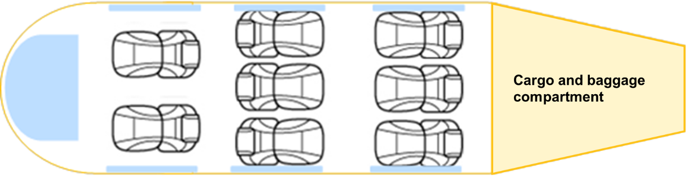
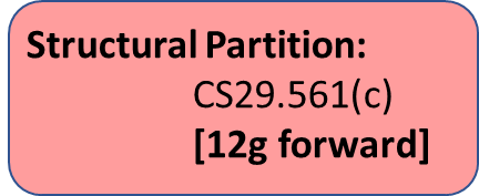
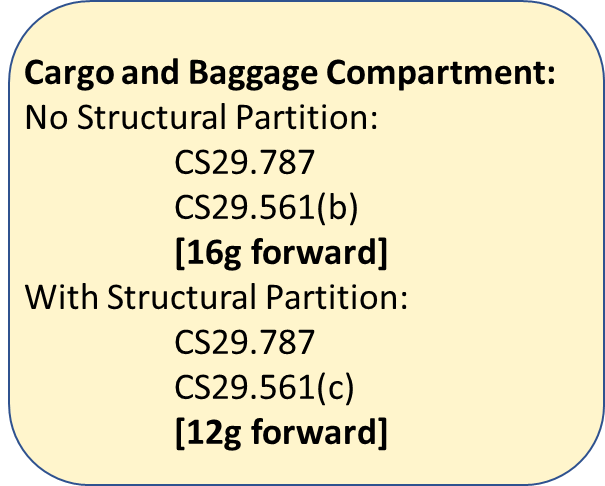
PROTECTION OF OCCUPANTS IN THE CABIN
The CS-29 objective is to protect the occupant within the cabin from forces up to those specified in CS 29.561(b)(3).
If the cabin is forward of the cargo or baggage compartment and is separated with a structural partition, this partition should be sized to 12g forward, as per the CS 29.787 requirement, regardless of the means used to restrain the items of mass in the cargo or baggage compartment. If a structural partition is not installed, then ultimate inertial load factors specified in CS 29.561(b)(3) apply to the restrain system of the items of mass (i.e. baggage, cargo, etc.).
Conditions to be considered:
[Amdt No: 29/11]
CS 29.801 Ditching
ED Decision 2023/001/R
(a)If certification with ditching provisions is requested by the applicant, the rotorcraft must meet the requirements of this CS and CS 29.563, CS 29.783(h), CS 29.803(c), CS 29.805(c), CS 29.807(d), CS 29.809(j), CS 29.811(h), CS 29.813(d), CS 29.1411, CS 29.1415, CS 29.1470, CS 29.1555(d) and CS 29.1561.
(b)Each practicable design measure, compatible with the general characteristics of the rotorcraft, must be taken to minimise the probability that when ditching, the behaviour of the rotorcraft would cause immediate injury to the occupants or would make it impossible for them to escape.
(c) An emergency flotation system that is stowed in a deflated condition during normal flight must:
(1) be designed such that the effects of a water impact (i.e. crash) on the emergency flotation system are minimised.
(2) have a means of automatic deployment following water entry. Automatic deployment must not rely on any pilot action during flight.
(d)The probable behaviour of the rotorcraft during ditching water entry must be must be shown to exhibit no unsafe characteristics.
(e)The rotorcraft must be shown to resist capsize in the sea conditions selected by the applicant. The probability of capsizing in a 5-minute exposure to the sea conditions must be substantiated to be less than or equal to 3.0 % with a fully serviceable emergency flotation system and 30.0 % with the critical float compartment failed, with 95 % confidence.
Allowances must be made for probable structural damage and leakage.
(f)Unless the effects of the collapse of external doors and windows are accounted for in the investigation of the probable behaviour of the rotorcraft during ditching (as prescribed in sub-paragraphs (d) and (e)), the external doors and windows must be designed to withstand the probable maximum local pressures.
(g) It must be shown that the rotorcraft will not sink following the functional loss of any single complete flotation unit.
[Amdt No: 29/5]
[Amdt No: 29/11]
AMC1 29.801 Ditching
ED Decision 2023/001/R
This AMC replaces FAA AC 29.801.
(a) Definitions
(1) Ditching: a controlled emergency landing on the water, deliberately executed in accordance with rotorcraft flight manual (RFM) procedures, with the intent of abandoning the rotorcraft as soon as practicable.
(2) Emergency flotation system (EFS): a system of floats and any associated parts (e.g. gas cylinders, means of deployment, pipework and electrical connections) that is designed and installed on a rotorcraft to provide buoyancy and flotation stability in a ditching.
(b) Explanation
(1) Ditching certification is performed only if requested by the applicant.
(2) For a rotorcraft to be certified for ditching, in addition to the other applicable requirements of CS-29, the rotorcraft must specifically meet CS 29.801 together with the requirements referenced in CS 29.801(a).
(3) Ditching certification encompasses four primary areas of concern: rotorcraft water entry and flotation stability (including loads and flotation system design), occupant egress, and occupant survival. CS-29 Amendment 5 has developed enhanced standards in all of these areas.
(4) The scope of the ditching requirements is expanded at Amendment 5 through a change in the ditching definition. All potential failure conditions that could result in a controlled ‘land immediately’ action by the pilot are now included. This primarily relates to changes in water entry conditions. While the limiting conditions for water entry have been retained (15.4 m/s, 1.5 m/s), the alleviation that previously allowed less than 15.4 m/s (30 kt) forward speed to be substantiated as the maximum applicable value has been removed (also from CS 29.563).
(5) Flotation stability is enhanced through the introduction of a new standard based on a probabilistic approach to capsizes.
(6) Failure of the EFS to operate when required will lead to the rotorcraft rapidly capsizing and sinking. Operational experience has shown that localised damage or failure of a single component of an EFS, or the failure of the flight crew to activate or deploy the EFS, can lead to the loss of the complete system. Therefore, the design of the EFS needs careful consideration; automatic arming and deployment have been shown to be practicable and to offer a significant safety benefit.
(7) The sea conditions, on which certification with ditching provisions is to be based, are selected by the applicant and should take into account the expected sea conditions in the intended areas of operation. The wave climate of the northern North Sea is adopted as the default wave climate as it represents a conservative condition. The applicant may also select alternative/additional sea areas with any associated certification then being limited to those geographical regions. The significant wave height, and any geographical limitations (if applicable – see the AMC to CS 29.801(e) and 29.802(c)) should be included in the RFM as performance information.
(8)During scale model testing, appropriate allowances should be made for probable structural damage and leakage. Previous model tests and other data from rotorcraft of similar configurations that have already been substantiated based on equivalent test conditions may be used to satisfy the ditching requirements. In regard to flotation stability, the test conditions should be equivalent to those defined in AMC to 29.801(e) and 29.802(c).
(9) CS 29.801(e) requires that after ditching in sea conditions for which certification with ditching provisions is requested by the applicant, the probability of capsizing in a 5 minute exposure is acceptably low in order to allow the occupants to leave the rotorcraft and enter life rafts. This should be interpreted to mean that up to and including the worst-case sea conditions for which certification with ditching provisions is requested by the applicant, the probability that the rotorcraft will capsize should be not higher than the target stated in the certification specification. An acceptable means of demonstrating post-ditching flotation stability is through scale model testing using irregular waves. The AMC to CS 29.801(e) and 29.802(c) contains a test specification that has been developed for this purpose.
(10) Providing a ‘wet floor’ concept (water in the cabin) by positioning the floats higher on the fuselage sides and allowing the rotorcraft to float lower in the water, can be a way of increasing the stability of a ditched rotorcraft (although this would need to be verified for the individual rotorcraft type for all weight and loading conditions), or it may be desirable for other reasons. This is permissible provided that the mean static level of water in the cabin is limited to being lower than the upper surface of the seat cushion (for all rotorcraft mass and centre of gravity cases, with all flotation units intact), and that the presence of water will not unduly restrict the ability of occupants to evacuate the rotorcraft and enter the life raft.
(11) It should be shown by analysis or other means that the rotorcraft will not sink following the functional loss of any single complete ditching flotation unit. Experience has shown that in water impact events, the forces exerted on the emergency flotation unit that first comes into contact with the water surface, together with structural deformation and other damage, can render the unit unusable. Maintenance errors may also lead to a flotation unit failing to inflate. The ability of occupants to egress successfully is significantly increased if the rotorcraft does not sink. However, this requirement is not intended for any other purpose, such as aiding salvage of the rotorcraft. Therefore, consideration of the remaining flotation units remaining inflated for an especially long period, i.e. longer than required in the upright floating case, is not required.
(12) The sea conditions approved for ditching should be stated in the performance information section of the RFM.
(13) Current practices allow wide latitude in the design of cabin interiors and, consequently, of stowage provisions for safety and ditching equipment. Rotorcraft manufacturers may deliver aircraft with unfinished (green) interiors that are to be completed by a modifier.
(i) Segmented certification is permitted to accommodate this practice. That is, the rotorcraft manufacturer shows compliance with the flotation time, stability, and emergency exit requirements while a modifier shows compliance with the equipment and egress requirements with the interior completed. This procedure requires close cooperation and coordination between the manufacturer, modifier, and EASA.
(ii) The rotorcraft manufacturer may elect to establish a token interior for ditching certification. This interior may subsequently be modified by a supplemental type certificate (STC). The ditching provisions should be shown to be compliant with the applicable requirements after any interior configuration or limitation change.
(iii) The RFM and any RFM supplements deserve special attention if a segmented certification procedure is pursued.
(c) Procedures
(1) Flotation system design
(i) Structural integrity should be established in accordance with CS 29.563.
(ii) Rotorcraft handling qualities should be verified to comply with the applicable certification specifications throughout the approved flight envelope with floats installed. Where floats are normally deflated, and deployed in flight, the handling qualities should be verified for the approved operating envelopes with the floats in:
(A) the deflated and stowed condition;
(B)the fully inflated condition; and
(C)the in-flight inflation condition; for float systems which may be inflated in flight, rotorcraft controllability should be verified by test or analysis, taking into account all possible emergency flotation system inflation failures.
(iii) Reliability should be considered in the basic design to assure approximately equal inflation of the floats to preclude excessive yaw, roll, or pitch in flight or in the water:
(A) Maintenance procedures should not degrade the flotation system (e.g. by introducing contaminants that could affect normal operation, etc.).
(B) The flotation system design should preclude inadvertent damage due to normal personnel traffic flow and wear and tear. Protection covers should be evaluated for function and reliability.
(C) The designs of the floats should provide means to minimise the likelihood of damage or tear propagation between compartments. Single compartment float designs should be avoided.
(D) When showing compliance with CS 29.801(c)(1), and where practicable, the design of the flotation system should consider the likely effects of water impact (i.e. crash) loads. For example:
(a) locate system components away from the major effects of structural deformation;
(b)use redundant or distributed systems;
(c) use flexible pipes/hoses; and
(d) avoid passing pipes/hoses or electrical wires through bulkheads that could act as a ‘guillotine’ when the structure is subject to water impact loads.
(iv) The floats should be fabricated from highly conspicuous material to assist in the location of the rotorcraft following a ditching (and possible capsize).
(2) Flotation system inflation.
Emergency flotation systems (EFSs) that are normally stowed in a deflated condition and are inflated either in flight or after contact with water should be evaluated as follows:
(i) The emergency flotation system should include a means to verify its system integrity prior to each flight.
(ii) Means should be provided to automatically trigger the inflation of the EFS upon water entry, irrespective of whether or not inflation prior to water entry is the intended operation mode. If a manual means of inflation is provided, the float activation switch should be located on one of the primary flight controls and should be safeguarded against inadvertent actuation.
(iii) The inflation system should be shown to have an appropriately low probability of spontaneous or inadvertent actuation in flight conditions for which float deployment has not been demonstrated to be safe. If this is achieved by disarming of the inflation system, this should be achieved by the use of an automatic system employing appropriate input parameters. The choice of input parameters, and architecture of the system, should such that rearming of the system occurs automatically in a manner that will assure the inflation system functions as intended in the event of a water impact. As required by CS 29.801(c), in achieving this, it is not acceptable to specify any pilot action during flight. Float disarming is typically required at high airspeeds, and could be achieved automatically using an airspeed switch. However, this would retain the possibility of inadvertent flight into the water at high airspeed, with the risk that the floats would not deploy. This scenario could be addressed by providing an additional or alternative means of rearming the floats as the aircraft descends through an appropriate height threshold. A height below that of the majority of offshore helidecks could be chosen in order to minimise exposure to inadvertent activation above the demonstrated float deployment airspeed.
(iv)The maximum airspeeds for intentional in-flight actuation of the emergency flotation system and for flight with the floats inflated should be established as limitations in the RFM unless in-flight actuation is prohibited by the RFM.
(v) Activation of the emergency flotation system upon water entry (irrespective of whether or not inflation prior to water entry is the intended operation mode) should result in an inflation time short enough to prevent the rotorcraft from becoming excessively submerged.
(vi) A means should be provided for checking the pressure of the gas storage cylinders prior to take-off. A table of acceptable gas cylinder pressure variation with ambient temperature and altitude (if applicable) should be provided.
(vii) A means should be provided to minimise the possibility of over inflation of the flotation units under any reasonably probable actuation conditions.
(viii) The ability of the floats to inflate without puncturing when subjected to actual water pressures should be substantiated. A demonstration of a full-scale float immersion in a calm body of water is one acceptable method of substantiation. Precautions should also be taken to avoid floats being punctured due to the proximity of sharp objects, during inflation in flight and with the helicopter in the water, and during subsequent movement of the helicopter in waves. Examples of objects that need to be considered are aerials, probes, overboard vents, unprotected split-pin tails, guttering and any projections sharper than a three-dimensional right-angled corner.
(ix) The inflation system design should, where practicable, minimise the possibility of foreseeable damage preventing the operation or partial operation of the EFS (e.g. interruption of the electrical supply or pipework). This could be achieved through the use of redundant systems or through distributed systems where each flotation unit is capable of autonomous operation (i.e. through the provision of individual inflation gas sources, electrical power sources and float activation switches).
(x) The inflation system design should minimise the probability that the floats do not inflate properly or inflate asymmetrically in the event of a ditching. This may be accomplished by interconnecting inflation gas sources, for which flexible hoses should be used to minimise potential damage, or by synchronising the deployment of autonomous flotation units. Note that the main concern in the event of a water impact is to prevent the rotorcraft from sinking; asymmetric deployment is a lesser concern.
(xi) CS 29.801(g) requires it to be shown that the rotorcraft will not sink following the functional loss of any complete flotation unit. A ’complete flotation unit’ shall be taken to mean a discrete, independently located float. The qualifying term ‘complete’ means that the entire structure of the flotation unit must be considered, not limited to any segregated compartments.
The loss of function of a flotation unit is most likely to be due to damage occurring in a water impact. However, there may be other reasons, such as undetected damage during maintenance, or incorrect maintenance. All reasonably probable causes for the loss of functionality of a flotation unit, and the resultant effect(s) on the remainder of the inflation system, should therefore be taken into account.
In the case of inflatable flotation units, irrespective of whether the intended operation is to deploy the system before or after water entry, the following shall be taken into account when assessing the ability of the rotorcraft to remain afloat;
—Following the functional loss of a deployed flotation unit, the capability to maintain pressure in the remaining inflation units should be justified on the basis of the inflation system design, for example:
—Individual inflation gas sources per flotation unit,
—Installation of non-return valves at appropriate locations.
—Following the functional loss of a non-deployed flotation unit, the capability of the remaining flotation units to deploy should be justified on the basis of the inflation system design, for example:
—The functionality of the inflation gas sources integrated with the functionally lost flotation unit in question should also either be assumed to be lost, or justification should otherwise be provided,
—The degree of inflation of the remaining undamaged flotation units, which share parts of the inflation system with the damaged unit, bearing in mind that the damaged unit will be venting, should be determined.
(3)Injury prevention during and following water entry.
An assessment of the cabin and cockpit layouts should be undertaken to minimise the potential for injury to occupants in a ditching. This may be performed as part of the compliance with CS 29.785. Attention should be given to the avoidance of injuries due to arm/leg flailing, as these can be a significant impediment to occupant egress and subsequent survivability. Practical steps that could be taken include:
(i) locating potentially hazardous equipment away from the occupants;
(ii) installing energy-absorbing padding onto interior components;
(iii) using frangible materials; and
(iv) designs that exclude hard or sharp edges.
(4) Water entry procedures.
Tests or simulations (or a combination of both) should be conducted to establish procedures and techniques to be used for water entry, based on the conditions given in (5). These tests/simulations should include determination of the optimum pitch attitude and forward velocity for ditching in a calm sea as well as entry procedures for the most severe sea condition to be certified. Procedures for all failure conditions that may lead to a ‘land immediately’ action (e.g. one engine inoperative, all engines inoperative, tail rotor/drive failure) should be established. However, only the procedures for the most critical all-engines-inoperative condition need be verified by water entry test data.
(5)Water entry behaviour.
CS 29.801(d) requires the probable behaviour of the rotorcraft to be shown to exhibit no unsafe characteristics, e.g. that would lead to an inability to remain upright.
This should be demonstrated by means of scale model testing, based on the following conditions:
(i)For entry into a calm sea:
(A) the optimum pitch, roll and yaw attitudes determined in (c)(5) above, with consideration for variations that would reasonably be expected to occur in service;
(B) ground speeds from 0 to 15.4 m/s (0 to 30 kt); and
(C) descent rate of 1.5 m/s (5 ft/s) or greater;
(ii) For entry into the most severe sea condition:
(A) the optimum pitch attitude and entry procedure as determined in (c)(5) above;
(B)ground speed of 15.4 m/s (30 kt);
(C)descent rate of 1.5 m/s (5 ft/s) or greater;
(D) likely roll and yaw attitudes; and
(E) sea conditions may be represented by regular waves having a height at least equal to the significant wave height (Hs), and a period no larger than the wave zero-crossing period (Tz) for the wave spectrum chosen for demonstration of rotorcraft flotation stability after water entry (see (c)(7) below and AMC to CS 29.801(e) and 29.802(c));
(iii) Scoops, flaps, projections, and any other factors likely to affect the hydrodynamic characteristics of the rotorcraft should be considered;
(iv) Probable damage to the structure due to water entry should be considered during the water entry evaluations (e.g. failure of windows, doors, skins, panels, etc.); and
(v) Rotor lift does not have to be considered.
Alternatively, if scale model test data for a helicopter of a similar configuration has been previously successfully used to justify water entry behaviour, this data could form the basis for a comparative analytical approach.
(6) Flotation stability tests.
An acceptable means of flotation stability testing is contained in the AMC to CS 29.801(e) and 29.802(c). Note that model tests in a wave basin on a number of different rotorcraft types have indicated that an improvement in seakeeping performance can consistently be achieved by fitting float scoops.
(7) Occupant egress and survival.
The ability of the occupants to deploy life rafts, egress the rotorcraft, and board the life rafts (directly, in the case of passengers), should be evaluated. For configurations which are considered to have critical occupant egress capabilities due to the life raft locations or the ditching emergency exit locations and the proximity of the float (or a combination of both), an actual demonstration of egress may be required. When a demonstration is required, it may be conducted on a full-scale rotorcraft actually immersed in a calm body of water or using any other rig or ground test facility shown to be representative. The demonstration should show that the floats do not impede a satisfactory evacuation. Service experience has shown that it is possible for occupants to have escaped from the cabin, but to have not been able to board a life raft and to have had difficulty in finding handholds to stay afloat and together. Handholds or lifelines should be provided on appropriate parts of the rotorcraft. The normal attitude of the rotorcraft and the possibility of capsizing should be considered when positioning the handholds or lifelines.
[Amdt No: 29/5]
[Amdt No: 29/11]
AMC2 29.801(e) and 29.802(c) Model test method for flotation stability
ED Decision 2023/001/R
This AMC should be used when showing compliance with CS 29.801(e) or CS 29.802(c) as introduced at Amendment 5.
(a)Explanation
(1) Model test objectives
The objective of the model tests described in the certification specification is to establish the performance of the rotorcraft in terms of its stability in waves. The wave conditions in which the rotorcraft is to be certified should be selected according to the desired level of operability (see (a)(2) below).
This will enable the overall performance of the rotorcraft to be established for inclusion in the rotorcraft flight manual (RFM) as required by CS 29.1587(c). In the case of approval with ditching provisions, the wave conditions selected for substantiation of behaviour during the water entry phase must also be taken into account.
The rotorcraft design is to be tested, at each mass condition (see paragraph b(1)(ii) below), with its flotation system intact, and with its single most critical flotation compartment damaged (i.e. the single-puncture case which has the worst adverse effect on flotation stability).
(2) Model test wave conditions
The rotorcraft is to be tested in a single sea condition comprising a single combination of significant wave height (Hs) and zero-crossing period (Tz). The values of Hs and Tz should be no less than, and no more than, respectively, those chosen for certification, i.e. as selected from table 1. This approach is necessary in order to constrain the quantity of testing required within reasonable limits and is considered to be conservative. The justification is detailed in Appendix 2.
The applicant is at liberty to certify the rotorcraft to any significant wave height Hs. This significant wave height will be noted as performance information in the RFM.
Using reliable wave climate data for an appropriate region of the ocean for the anticipated flight operations, a Tz is selected to accompany the Hs. This Tz should be typical of those occurring at Hs as determined in the wave scatter table for the region. The mode or median of the Tz distribution at Hs should be used.
It is considered that the northern North Sea represents a conservatively ‘hostile’ region of the ocean worldwide and should be adopted as the default wave climate for certification. However, this does not preclude an applicant from certifying a rotorcraft specifically for a different region. Such a certification for a specific region would require the geographical limits of that certification region to be noted as performance information in the RFM. Certification for the default northern North Sea wave climate does not require any geographical limits.
In the case of an approval with emergency flotation provisions, operational limitations may limit flight to ‘non-hostile’ sea areas. For simplicity, the northern North Sea may still be selected as the wave climate for certification, or alternatively a wave climate derived from a non-hostile region’s data may be used. If the latter approach is chosen, and it is desired to avoid geographical limits, a ‘non-hostile’ default wave climate will need to be agreed with EASA.
Wave climate data for the northern North Sea were obtained from the United Kingdom Meteorological Office (UK Met Office) for a typical ‘hostile’ helicopter route. The route selected was from Aberdeen to Block 211/27 in the UK sector of the North Sea. Data tables were derived from a UK Met Office analysis of 34 years of 3-hourly wave data generated within an 8-km, resolved wave model hindcast for European waters. This data represents the default wave climate.
Table 1 below has been derived from this data and contains combinations of significant Hs and Tz. Table 1 also includes the probability of exceedance (Pe) of the Hs.
Table 1 — Northern North Sea wave climate
Spectrum shape: JONSWAP, peak enhancement factor γ = 3.3 | ||||
Significant wave height Hs | Mean wave period Tz | Significant steepness Ss = 2πHs/(gTz2) | Hs probability of exceedance Pe | |
Intact flotation system | 6 m | 7.9 s | 1/16.2 | 1.2 % |
5.5 m | 7.6 s | 1/16.4 | 2 % | |
5 m | 7.3 s | 1/16.6 | 3 % | |
4.5 m | 7.0 s | 1/17.0 | 5 % | |
4 m | 6.7 s | 1/17.5 | 8 % | |
3.5 m | 6.3 s | 1/17.7 | 13 % | |
3 m | 5.9 s | 1/18.1 | 20 % | |
2.5 m | 5.5 s | 1/18.9 | 29 % | |
2 m | 5.1 s | 1/20.3 | 43 % | |
1.25 m | 4.4 s | 1/24.2 | 72 % | |
(3) Target probability of capsizing
Target probabilities of capsizing have been derived from a risk assessment. The target probabilities to be applied are stated in CS 29.801(e) and 29.802(c), as applicable.
For ditching, the intact flotation system probability of capsizing of 3 % is derived from a historic ditching rate of 3.32 x 10⁻⁶ per flight hour and an AC 29.1309 consequence of hazardous, which implies a frequency of capsizing of less than 10-7 per flight hour. The damaged flotation system probability of capsizing is increased by a factor of 10 to 30 % on the assumption that the probability of failure of the critical float compartment is 0.1; this probability has been estimated, as there is insufficient data on flotation system failure rates.
For emergency flotation equipment, an increase of half an order (√10) is allowed on the assumption of a reduced exposure to the risk, resulting in a probability of capsizing of 10 %. The probability of a capsizing with a damaged flotation system is consequently increased to 100 %, hence no test is required.
(4) Intact flotation system
For the case of an intact flotation system, if the northern North Sea default wave climate has been chosen for certification, the rotorcraft should be shown to resist capsize in a sea condition selected from Table 1. The probability of capsizing in a 5-minute exposure to the selected sea condition is to be demonstrated to be less than or equal to the value provided in CS 29.801(e) or 29.802(c), as appropriate, with a confidence of 95 % or greater.
(5)Damaged flotation system
For the case of a damaged flotation compartment (see (1) above), the same sea condition may be used, but a 10-fold increased probability of capsizing is permitted. This is because it is assumed that flotation system damage will occur in approximately one out of ten emergency landings on water. Thus, the probability of capsizing in a 5-minute exposure to the sea condition is to be demonstrated to be less than or equal to 10 times the required probability for the intact flotation system case, with a confidence of 95 % or greater. Where a 10-times probability is equal to or greater than 100 %, it is not necessary to perform a model test to determine the capsize probability with a damaged flotation system.
Alternatively, the applicant may select a wave condition with 10 times the probability of exceedance Pe of the significant wave height (Hs) selected for the intact flotation condition. In this case, the probability of capsizing in a 5-minute exposure to the sea condition is to be demonstrated to be less than or equal to the required value (see CS 29.801(e) or 29.802(c)), with a confidence of 95 % or greater.
(6) Long-crested waves
Whilst it is recognised that ocean waves are in general multidirectional (short-crested), the model tests are to be performed in unidirectional (long-crested) waves, this being regarded as a conservative approach to capsize probability.
(b) Procedures
(1)Rotorcraft model
(i) Construction and scale of the model
The rotorcraft model, including its emergency flotation, is to be constructed to be geometrically similar to the full-scale rotorcraft design at a scale that will permit the required wave conditions to be accurately represented in the model basin. It is recommended that the scale of the model should be not smaller than 1/15.
The construction of the model is to be sufficiently light to permit the model to be ballasted to achieve the desired weight and rotational inertias specified in the mass conditions (see (b)(1)(ii) below)6.
Where it is likely that water may flood into the internal spaces following an emergency landing on water, for example through doors opened to permit escape, or any other opening, the model should represent these internal spaces and openings as realistically as possible.
It is permissible to omit the main rotor(s) from the model, but its (their) mass is to be represented in the mass and inertia conditions7.
(ii) Mass conditions
As it is unlikely that the most critical condition can be determined reliably prior to testing, the model is to be tested in two mass conditions:
(A)maximum mass condition, mid C of G; and
(B) minimum mass condition, mid C of G.
(iii)Mass properties
The model is to be ballasted in order to achieve the required scale weight, centre of gravity, roll and yaw inertia for each of the mass conditions to be tested.
Once ballasted, the model’s floating draft and trim in calm water is to be checked and compared with the design floating attitude.
The required mass properties and floating draft and trim, and those measured during model preparation, are to be fully documented and compared in the report.
(iv) Model restraint system
The primary method of testing is with a restrained model, but an alternative option is for a free-floating model (See (3)(iii) below).
For the primary restrained method, a flexible restraint or mooring system is to be provided to restrain the model in order for it to remain beam-on to the waves in the model basin8.
This restraint system should fulfil the following criteria:
(A)be attached to the model on the centre line at the front and rear of the fuselage in such a position that roll motion coupling is minimised; an attachment at or near the waterline is preferred; and
(B) be sufficiently flexible that the natural frequencies of the model surging/swaying on this restraint system are much lower than the lowest wave frequencies in the spectrum.
(v) Sea anchor
Whether or not the rotorcraft is to be fitted with a sea anchor, such an anchor is not to be represented in these model tests9.
(2) Test facility
The model test facility is to have the capability to generate realistic long non-repeating sequences of unidirectional (long-crested) irregular waves, as well as the characteristic wave condition at the chosen model scale. The facility is to be deep enough to ensure that the waves are not influenced by the depth (i.e. deep-water waves).
The dimensions of the test facility are to be sufficiently large to avoid any significant reflection/refraction effects influencing the behaviour of the rotorcraft model.
The facility is to be fitted with a high-quality wave-absorbing system or beach.
The model basin is to provide full details of the performance of the wave maker and the wave absorption system prior to testing.
(3) Model test set-up
(i)General
The model is to be installed in the wave facility in a location sufficiently distant from the wave maker, tank walls and beach/absorber such that the wave conditions are repeatable and not influenced by the boundaries.
The model is to be attached to the model restraint system (see (b)(1)(iv) above).
(ii) Instrumentation and visual records
During wave calibration tests, three wave elevation probes are to be installed and their outputs continuously recorded. These probes are to be installed at the intended model location, a few metres to the side and a few metres ahead of this location.
The wave probe at the model location is to be removed during tests with the rotorcraft model present.
All tests are to be continuously recorded on digital video. It is required that at least two simultaneous views of the model are to be recorded. One is to be in line with the model axis (i.e. viewing along the wave crests), and the other is to be a three-quarter view of the model from the up-wave direction. Video records are to incorporate a time code to facilitate synchronisation with the wave elevation records in order to permit the investigation of the circumstances and details of a particular capsize event.
(iii)Wave conditions and calibration
Prior to the installation of the rotorcraft model in the test facility, the required wave conditions are to be pre-calibrated.
Wave elevation probes are to be installed at the model location, alongside and ahead of the intended model location.
The intended wave spectrum is to be run for the full exposure duration required to demonstrate the required probability of capsizing. The analysis of these wave calibration runs is to be used to:
(A) confirm that the required wave spectrum has been obtained at the model location; and
(B) verify that the wave spectrum does not deteriorate appreciably during the run in order to help establish the maximum duration test that can be run before the test facility must be allowed to become calm again.
It should be demonstrated that the wave spectrum measured at each of the three locations is the same.
If a free-floating model is to be used, then the waves are to be calibrated for a range of locations down the basin, and the spectrum measured in each of these locations should be shown to be the same. The length of the basin covered by this range will be the permitted test region for the free-floating model, and the model will be recovered when it drifts outside this region (See paragraph 4 below). It should be demonstrated that the time series of the waves measured at the model location does not repeat during the run. Furthermore, it should be demonstrated that one or more continuation runs can be performed using exactly the same wave spectrum and period, but with different wave time series. This is to permit a long exposure to the wave conditions to be built up from a number of separate runs without any unrealistic repetition of the time series.
No wind simulation is to be used10.
(iv) Required wave run durations
The total duration of runs required to demonstrate that the required probability of capsizing has been achieved (or bettered) is dependent on that probability itself, and on the reliability or confidence of the capsize probability required to be demonstrated.
With the assumption that each 5-minute exposure to the wave conditions is independent, the equations provided in (b)(5) below can be used to determine the duration without a capsize that is required to demonstrate the required performance11. (See Appendix 1 below for examples.)
(4) Test execution and results
Tests are to start with the model at rest and the wave basin calm.
Following the start of the wave maker, sufficient time is to elapse to permit the slowest (highest-frequency) wave components to arrive at the model, before data recording starts.
Wave runs are to continue for the maximum permitted duration determined in the wave calibration test, or in the free-floating option for as long as the model remains in the calibrated wave region. Following sufficient time to allow the basin to become calm again, additional runs are to be conducted until the necessary total exposure duration (TTest) has been achieved (see (b)(5) below).
In the case of the free-floating option, the model may be recovered and relaunched without stopping the wave maker, provided that the maximum permitted duration has not been exceeded. See paragraph (4)(iv) for requirements regarding relaunching the free-floating model.
If and when a model capsize occurs, the time of the capsize from the start of the run is to be recorded, and the run stopped. The model is to be recovered, drained of any water, and reset in the basin for a continuation run to be performed.
There are a number of options that may be taken following a capsize event:
(i) Continuing with the same model configuration
If the test is to be continued with the same model configuration, the test can be restarted with a different wave time series, or continued from the point of capsizing in a pseudorandom time series.
(ii) Reducing the wave severity to achieve certification at a lower significant wave height.
Provided that the same basic pseudorandom wave time series can be reproduced by the wave basin at a lower wave height and corresponding period, it is permitted to restart the wave maker time series at a point at least 5 minutes prior to the capsize event, and if the model is now seen to survive the wave sequence that caused a capsize in the more severe condition, then credit can then be taken for the run duration successfully achieved prior to the capsize. Clearly, such a restart is only possible with a model basin using pseudorandom wave generation.
This method is only permitted if the change in significant wave height and period is sufficiently small that the same sequence of capsizing waves, albeit at a lower amplitude, can be seen in the wave basin. If this is not the case, then credit cannot be taken for the exposure time prior to capsize, and the wave time series must be restarted from the beginning.
(iii) Modifying the model with the intention of avoiding a capsize
If it is decided to modify the model flotation with the intention of demonstrating that the modified model does not capsize in the wave condition, then the pseudorandom wave maker time series should be restarted at a point at least 5 minutes prior to the capsize event so that the model is seen to survive the wave that caused a capsize prior to the modification. Credit can then be taken for the duration of the run successfully achieved prior to the capsize.
(iv) Repeating a restrained capsize event with a free-floating model
If it is suspected that the model restraint system might have contributed to the capsize, then it is permitted to repeat that part of the pseudorandom time series with a free-floating model. The model is to be temporally restrained with light lines and then released beam-on to the waves such that the free-floating model is seen to experience the same wave time series that caused a capsize in exactly the same position in the basin. It is accepted that it might require several attempts to find the precise model release time and position to achieve this.
If the free-floating, model having been launched beam-on to the waves, is seen to yaw into a more beneficial heading once released, and seen to survive the wave that caused a capsize in the restrained model, then this is accepted as negating the capsize seen with the restrained model.
The test may then continue with a restrained model as with (i) above.
(v) Special considerations regarding relaunching a free-floating model into the calibrated wave region
If a free-floating model is being used for the tests, then it is accepted that the model will need to be recovered as it leaves the calibrated wave region, and then relaunched at the top of that region. It is essential that this process does not introduce any statistical or other bias into the behaviour of the model. For example, there might be a natural tendency to wait for a spell of calmer waves into which to launch the model. This particular bias is to be avoided by strictly obeying a fixed time delay between recovery and relaunch.
Any water accumulated inside the model is not to be drained prior to the relaunch.
If the model has taken up a heading to the waves that is not beam-on, then it is permissible to relaunch the model at that same heading.
In all the above cases continuation runs are to be performed until the total duration of exposure to the wave condition is sufficient to establish that the 5-minute probability of capsizing has been determined with the required confidence of 95 %.
(5) Results analysis
Given that it has been demonstrated that the wave time series are non-repeating and statistically random, the results of the tests may be analysed on the assumption that each five-minute element of the total time series is independent.
If the model rotorcraft has not capsized during the total duration of the tests, the confidence that the probability of capsizing within 5 minutes is less than the target value of Pcapsize(target), as shown below:
and so the total duration of the model test required without capsize is provided by:
where:
(A) Ttest is the required full-scale duration of the test (in seconds);
(B) Pcapsize(target) is the required maximum probability of capsizing within 5 minutes;
(C)Tcriterion is the duration (in seconds) in which the rotorcraft must meet the no-capsize probability (= 5 x 60 s), as defined in CS 29.801(e); and
(D)C is the required confidence that the probability of capsizing has been achieved (0.95).
If the rotorcraft has capsized Ncapsize times during the tests, the probability of capsizing within 5 minutes can be estimated as:
and the confidence that the required capsize criteria have been met is:
It should be noted that, if the rotorcraft is permitted to fly over sea conditions with significant wave heights above the certification limit, then Pcapsize(target) should be reduced by the probability of exceedance of the certification limit for the significant wave height (Pe) (see Appendix 2 below).
(c) Deliverables
(1) A comprehensive report describing the model tests, the facility they were performed in, the model properties, the wave conditions used, the results of the tests, and the method of analysis to demonstrate compliance with CS 29.801(d) and (e).
(2)Conclusions in this report are to clarify the compliance (or otherwise) with those requirements.
(3)Digital video and data records of all tests performed.
(4) A specification for a certification model test should also be expected to include:
(i) an execution plan and time scale;
(ii)formal progress reports on content and frequency; and
(iii) quality assurance requirements.
[Amdt No: 29/5]
[Amdt No: 29/11]
Appendix 1 — Worked example
ED Decision 2018/007/R
The target 5-minute capsize probabilities for a rotorcraft certified to CS 29.801 are:
Certification with ditching provisions;
Fully serviceable emergency flotation system (EFS) - 3 %
Critical flotation compartment failed - 30 %
Certification with emergency flotation provisions;
Fully serviceable emergency flotation system (EFS) - 10 %
Critical flotation compartment failed - no demonstration required
One option available to the rotorcraft designer is to test at the selected wave height and demonstrate a probability of capsizing no greater than these values. However, to enhance offshore helicopter safety, some national aviation authorities (NAAs) have imposed restrictions that prevent normal operations (i.e. excluding emergencies, search and rescue (SAR), etc.) over sea conditions that are more severe than those for which performance has been demonstrated. In such cases, the helicopter may be operationally limited.
These operational restrictions may be avoided by accounting for the probability of exposure to sea conditions that exceed the selected wave height by certifying the rotorcraft for a lower probability of capsizing. Since it is conservatively assumed that the probability of capsizing in sea conditions that exceed the certified wave height is unity, the lower capsize probability required to be met is the target value minus the probability of the selected wave height being exceeded. However, it should also be noted that, in addition to restricting normal helicopter overwater operations to the demonstrated capability, i.e. the applicant’s chosen significant wave height limit (Hs(limit)), an NAA may declare a maximum limit above which all operations will be suspended due to the difficulty of rescuing persons from the sea in extreme conditions. There will, therefore, be no operational benefit in certifying a rotorcraft for sea conditions that exceed the national limits for rescue.
In the following examples, we shall use the three target probabilities of capsizing without any reduction to avoid operational restrictions. The test times quoted are full-scale times; to obtain the actual model test run time, these times should be divided by the square root of the model scale.
Certification with ditching provisions — fully serviceable EFS
Taking this first case, we need to demonstrate a ≤ 3 % probability of capsizing with a 95 % confidence. Applying equation (5)(i) above, this can be achieved with a 499-minute (full-scale time) exposure to the sea condition without a capsize.
Rearranging this equation, we have:
Alternatively, applying equation (5)(ii) above, the criterion would also be met if the model were seen to capsize just three times (for example) in a total 21.5 hours of exposure to the sea condition, or four times (for example) in a total of 25.5 hours of exposure.
Equation (ii) cannot be readily rearranged to solve Ttest, so the easiest way to solve it is by using a spreadsheet on a trial-and-error method. For the four-capsize case, we find that a 25.5-hour exposure gives a confidence of 0.95.
Certification with ditching provisions — critical flotation compartment failed
In this case, we need to demonstrate a ≤ 30 % probability of capsizing with a 95 % confidence. This can be achieved with a 50-minute (full-scale time) exposure to the sea condition without a capsize.
As above, the criterion would also be met if the model were seen to capsize just three times (for example) in a total 2.2 hours of exposure to the sea condition, or four times (for example) in a total of 2.6 hours of exposure.
Solving by trial and error in a spreadsheet, we find that a 2.6-hour exposure with no more than four capsizes gives a confidence of 0.95.
Certification with emergency flotation provisions — fully serviceable EFS
In this case, we need to demonstrate a ≤ 10 % probability of capsizing with a 95 % confidence. By solving the equations as above, this can be achieved with a 150-minute (full-scale time) exposure to the sea condition without a capsize.
As above, the criterion would also be met if the model were seen to capsize just three times (for example) in a total 6.5 hours of exposure to the sea condition, or four times (for example) in a total of 7.6 hours of exposure.
Solving by trial and error in a spreadsheet we find that a 7.6-hour exposure with no more than four capsizes gives a confidence of 0.95.
Certification with ditching provisions — critical flotation compartment failed
As stated in CS 29.802(c), no demonstration of capsize resistance is required for the case of the critical float compartment having failed.
This is because the allowed factor of ten increase in the probability of capsizing, as explained in (a)(3) above, results in a probability of 100 %.
[Amdt No: 29/5]
Appendix 2 — Test specification rationale
ED Decision 2018/007/R
(a) Introduction
The overall risk of capsizing within the 5-minute exposure period consists of two components: the probability of capsizing in a given wave condition, and the probability of experiencing that wave condition in an emergency landing on water.
If it is assumed that an emergency landing on water occurs at random and is not linked with weather conditions, the overall risk of a capsize can be established by combining two pieces of information:
(1) The wave climate scatter table, which shows the probability of meeting any particular combination of Hs and Tz. An example scatter table is shown below in Figure 1 — Example of all-year wave scatter table. Each cell of the table contains the probability of experiencing a wave condition with Hs and Tz in the range provided. Thus, the total of all cells in the table adds up to unity.
(2) The probability of a capsize in a 5-minute exposure for each of these height/period combinations. This probability of capsizing is different for each helicopter design and for each wave height/period combination, and is to be established through scale model testing using the method defined above.
In theory, a model test for the rotorcraft design should be performed in the full range of wave height/period combinations covering all the cells in the scatter table. Clearly, wave height/period combinations with zero or very low probabilities of occurrence might be ignored. It might also be justifiably assumed that the probability of a capsize at very high wave heights is unity, and at very low wave heights, it is zero. However, there would still remain a very large number of intermediate wave height/period combinations that would need to be investigated in model tests, and it is considered that such a test programme would be too lengthy and costly to be practicable.
The objective here is therefore to establish a justifiable method of estimating the overall 5-minute capsize probability using model test results for a single-wave condition. That is a single combination of Hs and Tz. Such a method can never be rigorously linked with the safety objective, but it is proposed that it may be regarded as a conservative approximation.
(b)Test methodology
The proposed test methodology is as follows:
The rotorcraft designer selects a desired significant wave height limit Hs(limit) for the certification of his helicopter. Model tests are performed in the sea condition Hs(limit).
Tz(limit) (where Tz(limit) is the zero-crossing period most likely to accompany Hs(limit)) with the selected spectrum shape using the method specified above, and the 5-minute probability of capsizing (Pcapsize) established in this sea condition.
The way in which Pcapsize varies for other values of Hs and Tz is not known because it is not proposed to perform model tests in all the other possible combinations. Furthermore, there is no theoretical method to translate a probability of capsizing from one sea condition to another.
However, it is known that the probability of capsizing is related to the exposure to breaking waves of sufficient height, and that this is in turn linked with wave steepness. Hence:
(1) the probability of capsizing is likely to be higher for wave heights just less than Hs(limit) but with wave periods shorter than Tz(limit); and
(2)the probability of capsizing will be lower for the larger population of wave conditions with wave heights less than Hs(limit) and with wave periods longer than Tz(limit).
So, a reasonable and conservative assumption is that on average, the same Pcapsize holds good for all wave conditions with heights less than or equal to Hs(limit).
A further conservative assumption is that Pcapsize is unity for all wave heights greater than Hs(limit).
Using these assumptions, a comparison of the measured Pcapsize in Hs(limit) Tz(limit) against the target probability of capsizing (Pcapsize(target)) can be performed.
In jurisdictions where flying is not permitted when the wave height is above Hs(limit), the rotorcraft will have passed the certification criteria provided that Pcapsize ≤ Pcapsize(target).
In jurisdictions where flying over waves greater than Hs(limit) is permitted, the rotorcraft will have passed the certification criteria provided that Pcapsize ≤ Pcapsize(target) – Pe, where Pe is the probability of exceedance of Hs(limit). Clearly, in this case, it can be seen that it would not be permissible for the rotorcraft designer to select an Hs(limit) which has a probability of exceedance greater than Pcapsize(target).
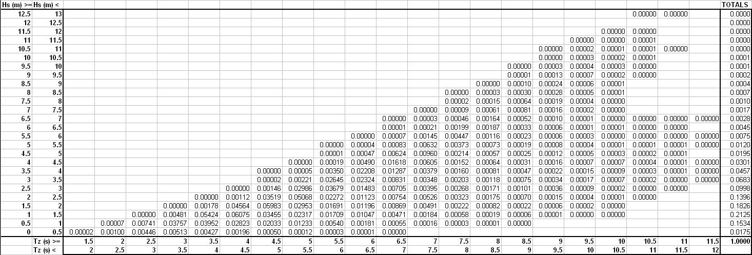
Figure 1 — Example of all-year wave scatter table
[Amdt No: 29/5]
CS 29.802 Emergency Flotation
ED Decision 2018/007/R
If operational rules allow, and only certification for emergency flotation equipment is requested by the applicant, the rotorcraft must be designed as follows;
(a) The rotorcraft must be equipped with an approved emergency flotation system.
(b) For a rotorcraft with a passenger seating capacity of 9 or less, the flotation units and their attachments to the rotorcraft must comply with CS 29.563. For a rotorcraft with a passenger seating capacity of 10 or more, the rotorcraft must comply with CS 29.563.
(c) The rotorcraft must be shown to resist capsize in the sea conditions selected by the applicant. The probability of capsizing in a 5-minute exposure to the sea conditions must be demonstrated to be less than or equal to 10.0 % with a fully serviceable emergency flotation system, with 95 % confidence. No demonstration of capsize resistance is required for the case of the critical float compartment having failed.
Allowances must be made for probable structural damage and leakage.
(d)It must be shown that the rotorcraft will not sink following the functional loss of any single complete flotation unit.
[Amdt No: 29/5]