
Filters
CS 29.1391 Minimum intensities in the horizontal plane of forward and rear position lights
ED Decision 2003/16/RM
Each position light intensity must equal or exceed the applicable values in the following table:
Dihedral angle (light included) | Angle from right or left of longitudinal axis, measured from dead ahead | Intensity (candelas) |
L and R (forward red and green) | 0° to 10° | 40 |
10° to 20° | 30 | |
20° to 110° | 5 | |
A (rear white) | 110° to 180° | 20 |
CS 29.1393 Minimum intensities in any vertical plane of forward and rear position lights
ED Decision 2003/16/RM
Each position light intensity must equal or exceed the applicable values in the following table:
Angle above or below the horizontal plane | Intensity |
0° | 1.00 I |
0° to 5° | 0.90 I |
5° to 10° | 0.80 I |
10° to 15° | 0.70 I |
15° to 20° | 0.50 I |
20° to 30° | 0.30 I |
30° to 40° | 0.10 I |
40° to 90° | 0.05 I |
CS 29.1395 Maximum intensities in overlapping beams of forward and rear position lights
ED Decision 2003/16/RM
No position light intensity may exceed the applicable values in the following table, except as provided in CS 29.1389(b)(3):
Overlaps | Maximum intensity | |
Area A (candelas) | Area B (candelas) | |
Green in dihedral angle L | 10 | 1 |
Red in dihedral angle R | 10 | 1 |
Green in dihedral angle A | 5 | 1 |
Red in dihedral angle A | 5 | 1 |
Rear white in dihedral angle L | 5 | 1 |
Rear white in dihedral angle R | 5 | 1 |
Where:
(a)Area A includes all directions in the adjacent dihedral angle that pass through the light source and intersect the common boundary plane at more than 10° but less than 20°; and
(b)Area B includes all directions in the adjacent dihedral angle that pass through the light source and intersect the common boundary plane at more than 20°.
CS 29.1397 Colour specifications
ED Decision 2003/16/RM
Each position light colour must have the applicable International Commission on Illumination chromaticity co-ordinates as follows:
(a)Aviation Red:
‘y’ is not greater than 0.335; and
‘z’ is not greater than 0.002.
(b)Aviation green:
‘x’ is not greater than 0.440–0.320y;
‘x’ is not greater than y–0.170; and
‘y’ is not less than 0.390–0.170x.
(c)Aviation white:
‘x’ is not less than 0.300 and not greater than 0.540;
‘y’ is not less than ‘x–0.040’ or ‘yo–0.010’, whichever is the smaller; and
‘y’ is not greater than ‘x+0.020’ nor ‘0.636–0.400x’.
Where ‘yo’ is the ‘y’ co-ordinate of the Planckian radiator for the value of ‘x’ considered.
CS 29.1399 Riding light
ED Decision 2003/16/RM
(a)Each riding light required for water operation must be installed so that it can:
(1)Show a white light for at least 4 km (two miles) at night under clear atmospheric conditions; and
(2)Show a maximum practicable unbroken light with the rotorcraft on the water.
(b)Externally hung lights may be used.
CS 29.1401 Anti-collision light system
ED Decision 2003/16/RM
(a)General. If certification for night operation is requested, the rotorcraft must have an anti-collision light system that:
(1)Consists of one or more approved anti-collision lights located so that their emitted light will not impair the crew’s vision or detract from the conspicuity of the position lights; and
(2)Meets the requirements of sub-paragraphs (b) to (f).
(b)Field of coverage. The system must consist of enough lights to illuminate the vital areas around the rotorcraft, considering the physical configuration and flight characteristics of the rotorcraft. The field of coverage must extend in each direction within at least 30° above and 30° below the horizontal plane of the rotorcraft, except that there may be solid angles of obstructed visibility totalling not more than 0.5 steradians.
(c)Flashing characteristics. The arrangement of the system, that is, the number of light sources, beam width, speed of rotation, and other characteristics, must give an effective flash frequency of not less than 40, nor more than 100, cycles per minute. The effective flash frequency is the frequency at which the rotorcraft's complete anti-collision light system is observed from a distance, and applies to each sector of light including any overlaps that exist when the system consists of more than one light source. In overlaps, flash frequencies may exceed 100, but not 180, cycles per minute.
(d)Colour. Each anti-collision light must be aviation red and must meet the applicable requirements of CS 29.1397.
(e)Light intensity. The minimum light intensities in any vertical plane, measured with the red filter (if used) and expressed in terms of ‘effective’ intensities, must meet the requirements of sub-paragraph (f). The following relation must be assumed:
where:
=effective intensity (candelas).
=instantaneous intensity as a function of time.
= flash time interval (seconds).
Normally, the maximum value of effective intensity is obtained when t2 and t1 are chosen so that the effective intensity is equal to the instantaneous intensity at t2 and t1.
(f)Minimum effective intensities for anti-collision light. Each anti-collision light effective intensity must equal or exceed the applicable values in the following table:
Angle above or below the horizontal plane | Effective intensity (candelas) |
0° to 5° | 150 |
5° to 10° | 90 |
10° to 20° | 30 |
20° to 30° | 15 |
SAFETY EQUIPMENT
CS 29.1411 General
ED Decision 2018/007/R
(a)Accessibility. Required safety equipment to be used by the crew in an emergency must be readily accessible.
(b)Stowage provisions. Stowage provisions for required safety equipment must be furnished and must:
(1)Be arranged so that the equipment is directly accessible and its location is obvious; and
(2)Protect the safety equipment from inadvertent damage.
(c)Emergency exit descent device. The stowage provisions for the emergency exit descent device required by CS 29.809(f) must be at the exits for which they are intended.
[Amdt No: 29/5]
AMC 29.1411 Safety equipment — General
ED Decision 2018/007/R
This AMC replaces FAA AC 29.1411.
(a) Explanation
CS-29 Amendment 5 introduced changes related to ditching and associated equipment. In particular, it defined a standard set of terminology, it simplified CS 29.1411 in line with it being a general certification specification for safety equipment, reorganised CS 29.1415 specifically for ditching equipment, and created a new CS 29.1470 on the installation and carriage of emergency locator transmitters (ELTs). All requirements relating to life raft installations are now co-located in CS 29.1415.
(1) The safety equipment should be accessible and appropriately stowed, and it should be ensured that:
(i)locations for stowage of all required safety equipment have been provided;
(ii) safety equipment is readily accessible to both crew members and passengers, as appropriate, during any reasonably probable emergency situation;
(iii) stowage locations for all required safety equipment will adequately protect such equipment from inadvertent damage during normal operations; and
(iv) safety equipment stowage provisions will protect the equipment from damage during emergency landings when subjected to the inertia loads specified in CS 29.561.
(b)Procedures
(1) A cockpit evaluation should be conducted to demonstrate that all required emergency equipment to be used by the flight crew will be readily accessible during any foreseeable emergency situation. This evaluation should include, for example, emergency flotation equipment actuation devices, remote life raft releases, door jettison handles, handheld fire extinguishers, and protective breathing equipment.
(2) Stowage provisions for safety equipment shown to be compatible with the vehicle configuration presented for certification should be provided and identified so that:
(i) equipment is readily accessible regardless of the operational configuration;
(ii) stowed equipment is free from inadvertent damage from passengers and handling; and
(iii) stowed equipment is adequately restrained to withstand the inertia forces specified in CS 29.561(b)(3) without sustaining damage.
(3) For rotorcraft required to have an emergency descent slide or rope according to CS 29.809(f), the stowage provisions for these devices should be located at the exits where those devices are intended to be used.
[Amdt No: 29/5]
CS 29.1413 Safety belts: passenger warning device
ED Decision 2003/16/RM
(a)If there are means to indicate to the passengers when safety belts should be fastened, they must be installed to be operated from either pilot seat.
(b)Each safety belt must be equipped with a metal to metal latching device.
AMC1 29.1413(a) Safety belts: passenger warning device
ED Decision 2023/001/R
INDICATION OF WHEN SEAT BELTS SHOULD BE FASTENED
If a means to indicate to the passengers when safety belts should be fastened is provided, it should consist of an illuminated sign or signs. At least one sign should be clearly visible to each passenger, when seated.
[Amdt No: 29/11]
CS 29.1415 Ditching equipment
ED Decision 2018/007/R
If certification with ditching provisions or emergency flotation provisions is requested by the applicant, the additional safety equipment required by any applicable operating rule must meet the requirements of this CS.
(a)All equipment must be approved.
(b)Life rafts.
(1)Required life raft(s) must be remotely deployable for use in an emergency. Remote controls capable of deploying the life raft(s) must be located within easy reach of the flight crew, occupants of the passenger cabin and survivors in the water, with the rotorcraft in the upright floating or capsized position. It must be substantiated that life raft(s) sufficient to accommodate all rotorcraft occupants, without exceeding the rated capacity of any life raft, can be reliably deployed with the rotorcraft in any reasonably foreseeable floating attitude, including capsized, and in the sea conditions chosen for demonstrating compliance with CS 29.801(e).
(2)Each life raft must have a short retaining line designed to hold the life raft near the rotorcraft and a long retaining line designed to keep the life raft attached to the rotorcraft. Both retaining lines must be designed to break before submerging the empty raft to which they are attached if the rotorcraft becomes totally submerged. The long retaining line must be of sufficient length that a drifting life raft will not be drawn towards any part of the rotorcraft that would pose a danger to the life raft itself or the persons on board.
(3) Each life raft must be substantiated as suitable for use in all sea conditions covered by the certification with ditching or emergency flotation provisions.
(4) The number of life rafts installed must be no less than two. The life rafts must be of an approximately equal rated capacity and buoyancy to accommodate all the occupants of the rotorcraft and unless excess life rafts of sufficient capacity are provided, the buoyancy and seating capacity beyond the rated capacity of each life raft (overload rating) must accommodate all occupants of the rotorcraft in the event of loss of one life raft of the largest rated capacity.
(c) Life preservers.
If the applicable operating rule allows for life preservers not to be worn at all times, stowage provisions must be provided that accommodate one life preserver for each occupant for which certification with ditching provisions is requested. A life preserver must be within easy reach of each occupant while seated.
(d)Survival equipment.
Approved survival equipment must be attached to each liferaft.
[Amdt No: 29/5]
AMC 29.1415 Ditching equipment
ED Decision 2018/007/R
This AMC replaces FAA AC 29.1415.
(a) Explanation
(1) Additional safety equipment is not required for all rotorcraft overwater operations. However, if such equipment is required by the applicable operating rule, the equipment supplied should satisfy this AMC.
NOTE: Although the term ‘ditching’ is most commonly associated with the design standards related to CS 29.801 (ditching approval), a rotorcraft equipped to the less demanding requirements of CS 29.802 (emergency flotation approval), when performing an emergency landing on to water, would nevertheless be commonly described as carrying out the process of ditching. The term ‘ditching equipment’ is therefore to be considered to apply to any safety equipment required by operational rule for operation over water.
It is a frequent practice for the rotorcraft manufacturer to provide the substantiation for only those portions of the ditching requirements relating to rotorcraft flotation and emergency exits. Completion of the ditching certification to include the safety equipment installation and stowage provisions is then left to the affected operator so that those aspects can best be adapted to the selected cabin interior. In such cases, the ‘Limitations’ section of the rotorcraft flight manual (RFM) should identify the substantiations yet to be provided in order to justify the full certification with ditching provisions. The modifier performing these final installations is then concerned directly with the details of this AMC. Any issues arising from aspects of the basic rotorcraft flotation and emergency exits certification that are not compatible with the modifier’s proposed safety equipment provisions should be resolved between the type certificate (TC) holder and the modifier prior to the certifying authority’s certification with ditching provisions (see AMC 29.801(b)(13) and AMC 29.1415(a)(2)(ii)).
(2) Compliance with the requirements of CS 29.801 for rotorcraft ditching requires compliance with the safety equipment stowage requirements and ditching equipment requirements of CS 29.1411 and CS 29.1415, respectively.
(i) Ditching equipment installed to complete ditching certification, or required by the applicable operating rule, should be compatible with the basic rotorcraft configuration presented for ditching certification. It is satisfactory if the ditching equipment is not incorporated at the time of the original rotorcraft type certification provided that suitable information is included in the ‘Limitations’ section of the rotorcraft flight manual (RFM) to identify the extent of ditching certification not yet completed.
(ii)When ditching equipment is being installed by a person other than the applicant who provided the rotorcraft flotation system and emergency exits, special care should be taken to avoid degrading the functioning of those items, and to make the ditching equipment compatible with them (see AMC 29.801(b)(13)).
(b) Procedures
All ditching equipment, including life rafts, life preservers, immersion suits, emergency breathing systems etc., should be of an approved type. Life rafts should be chosen to be suitable for use in all sea conditions covered by the certification with ditching provisions.
(1) Life rafts
(i) Life rafts are rated during their certification according to the number of people that can be carried under normal conditions and the number that can be accommodated in an overload condition. Only the normal rating may be used in relation to the number of occupants permitted to fly in the rotorcraft.
(ii) The life rafts should deploy on opposite sides of the rotorcraft in order to minimise the probability that all may be damaged during water entry/impact, and to provide the maximum likelihood that at least half of those provided will be useable in any wind condition.
(iii) Successful deployment of life raft installations should be demonstrated in all representative conditions. Testing should be performed, including underwater deployment, if applicable, to demonstrate that life rafts sufficient to accommodate all rotorcraft occupants, without exceeding the rated capacity of any life raft, will deploy reliably with the rotorcraft in any reasonably foreseeable floating attitude, including capsized. It should also be substantiated that reliable deployment will not be compromised by inertial effects from the rolling/pitching/heaving of the rotorcraft in the sea conditions chosen for the demonstration of compliance with the flotation/trim requirements of CS 29.801(e), or by intermittent submerging of the stowed raft location (if applicable) and the effects of wind. This substantiation should also consider all reasonably foreseeable rotorcraft floating attitudes, including capsized. Reasonably foreseeable floating attitudes are considered to be, as a minimum, upright, with and without loss of the critical emergency flotation system (EFS) compartment, and capsized, also with and without loss of the critical EFS compartment. Consideration should also be given towards maximising, where practicable, the likelihood of life raft deployment for other cases of EFS damage.
(iv) Rotorcraft fuselage attachments for the life raft retaining lines should be provided.
(A) Each life raft should be equipped with two retaining lines to be used for securing the life raft to the rotorcraft. The short retaining line should be of such a length as to hold the raft at a point next to an upright floating rotorcraft such that the occupants can enter the life raft directly without entering the water. If the design of the rotorcraft is such that the flight crew cannot enter the passenger cabin, it is acceptable that they would need to take a more indirect route when boarding the life raft. After life raft boarding is completed, the short retaining line may be cut and the life raft then remain attached to the rotorcraft by means of the long retaining line.
(B) Attachments on the rotorcraft for the retaining lines should not be susceptible to damage when the rotorcraft is subjected to the maximum water entry loads established by CS 29.563.
(C) Attachments on the rotorcraft for the retaining lines should be structurally adequate to restrain a fully loaded life raft.
(D)Life rafts should be attached to the rotorcraft by the required retaining lines after deployment without further action from the crew or passengers.
(E) It should be verified that the length of the long retaining line will not result in the life raft taking up a position which could create a potential puncture risk or hazard to the occupants, such as directly under the tail boom, tail rotor or main rotor disc.
(v) Life raft stowage provisions should be sufficient to accommodate rafts for the maximum number of occupants for which certification for ditching is requested by the applicant.
(vi) Life raft activation
The following should be provided for each life raft:
(A)primary activation: manual activation control(s), readily accessible to each pilot on the flight deck whilst seated;
(B)secondary activation: activation control(s) accessible from the passenger cabin with the rotorcraft in the upright or capsized position; if any control is located within the cabin, it should be protected from inadvertent operation; and
(C) tertiary activation: activation control(s) accessible to a person in the water, with the rotorcraft in any foreseeable floating attitude, including capsized.
It is acceptable for two of these manual activation functions to be incorporated into one control.
Automatic life raft activation is not prohibited (e.g. it could be triggered by water immersion). However, such a capability should be provided in addition to the above manual activation controls, not instead of them, and issues such as inadvertent deployment in flight and the potential for damage from turning rotors during deployment on the water should be mitigated.
Placards should be installed, of appropriate size, number and location, to highlight the location of each of the above life raft activation controls. All reasonably foreseeable rotorcraft floating attitudes should be considered.
(vii)Protection of life rafts from damage
Service experience has shown that following deployment, life rafts are susceptible to damage while in the water adjacent to the rotorcraft due to projections on the exterior of the rotorcraft such as antennas, overboard vents, unprotected split pin tails, guttering, etc. and any projections sharper than a three dimensional right angled corner. Projections likely to cause damage to a deployed life raft should be avoided by design, or suitably protected to minimise the likelihood of their causing damage to a deployed life raft. In general, projections on the exterior surface of the helicopter, that are located in a zone delineated by boundaries that are 1.22 m (4 ft) above and 0.61 m (2 ft) below the established static water line should be assessed. Relevant maintenance information should also provide procedures for maintaining such protection for rotorcraft equipped with life rafts. Furthermore, due account should be taken of the likely damage that may occur (e.g. disintegration of carbon-fibre panels or structure) during water entry and its potential hazard to deployed life rafts.
(2) Life preservers.
No provision for the stowage of life preservers is necessary if the applicable operating rule mandates the need for constant-wear life preservers.
(3) Emergency signalling equipment
Emergency signalling equipment required by the applicable operating rule should be free from hazards in its operation, and operable using either bare or gloved hands. Required signalling equipment should be easily accessible to the passengers or crew and located near a ditching emergency exit or included in the survival equipment attached to the life rafts.
[Amdt No: 29/5]
CS 29.1419 lce protection
ED Decision 2003/16/RM
(a)To obtain certification for flight into icing conditions, compliance with this paragraph must be shown.
(b)It must be demonstrated that the rotorcraft can be safely operated in the continuous maximum and intermittent maximum icing conditions determined under Appendix C within the rotorcraft altitude envelope. An analysis must be performed to establish, on the basis of the rotorcraft’s operational needs, the adequacy of the ice protection system for the various components of the rotorcraft.
(c)In addition to the analysis and physical evaluation prescribed in sub-paragraph (b), the effectiveness of the ice protection system and its components must be shown by flight tests of the rotorcraft or its components in measured natural atmospheric icing conditions and by one or more of the following tests as found necessary to determine the adequacy of the ice protection system:
(1)Laboratory dry air or simulated icing tests, or a combination of both, of the components or models of the components.
(2)Flight dry air tests of the ice protection system as a whole, or its individual components.
(3)Flight tests of the rotorcraft or its components in measured simulated icing conditions.
(d)The ice protection provisions of this paragraph are considered to be applicable primarily to the airframe. Powerplant installation requirements are contained in Subpart E of this CS-29.
(e)A means must be identified or provided for determining the formation of ice on critical parts of the rotorcraft. Unless otherwise restricted, the means must be available for night- time as well as daytime operation. The rotorcraft flight manual must describe the means of determining ice formation and must contain information necessary for safe operation of the rotorcraft in icing conditions.
Appendix C – Icing Certification
ED Decision 2003/16/RM
(a)The maximum continuous intensity of atmospheric icing conditions (continuous maximum icing) is defined by the variables of the cloud liquid water content, the mean effective diameter of the cloud droplets, the ambient air temperature, and the interrelationship of these three variables as shown in figure 1 of this appendix. The limiting icing envelope in terms of altitude and temperature is given in figure 2 of this appendix. The interrelationship of cloud liquid water content with drop diameter and altitude is determined from figures 1 and 2. The cloud liquid water content for continuous maximum icing conditions of a horizontal extent, other than 32.2 km (17.4 nautical miles), is determined by the value of liquid water content of figure 1, multiplied by the appropriate factor from figure 3 of this appendix.
(b)The intermittent maximum intensity of atmospheric icing conditions (intermittent maximum icing) is defined by the variables of the cloud liquid water content, the mean effective diameter of the cloud droplets, the ambient air temperature, and the interrelationship of these three variables as shown in figure 4 of this appendix. The limiting icing envelope in terms of altitude and temperature is given in figure 5 of this appendix. The interrelationship of cloud liquid water content with drop diameter and altitude is determined from figures 4 and 5. The cloud liquid water content for intermittent maximum icing conditions of a horizontal extent, other than 4.8 km (2.6 nautical miles), is determined by the value of cloud liquid water content of figure 4 multiplied by the appropriate factor in figure 6 of this appendix.
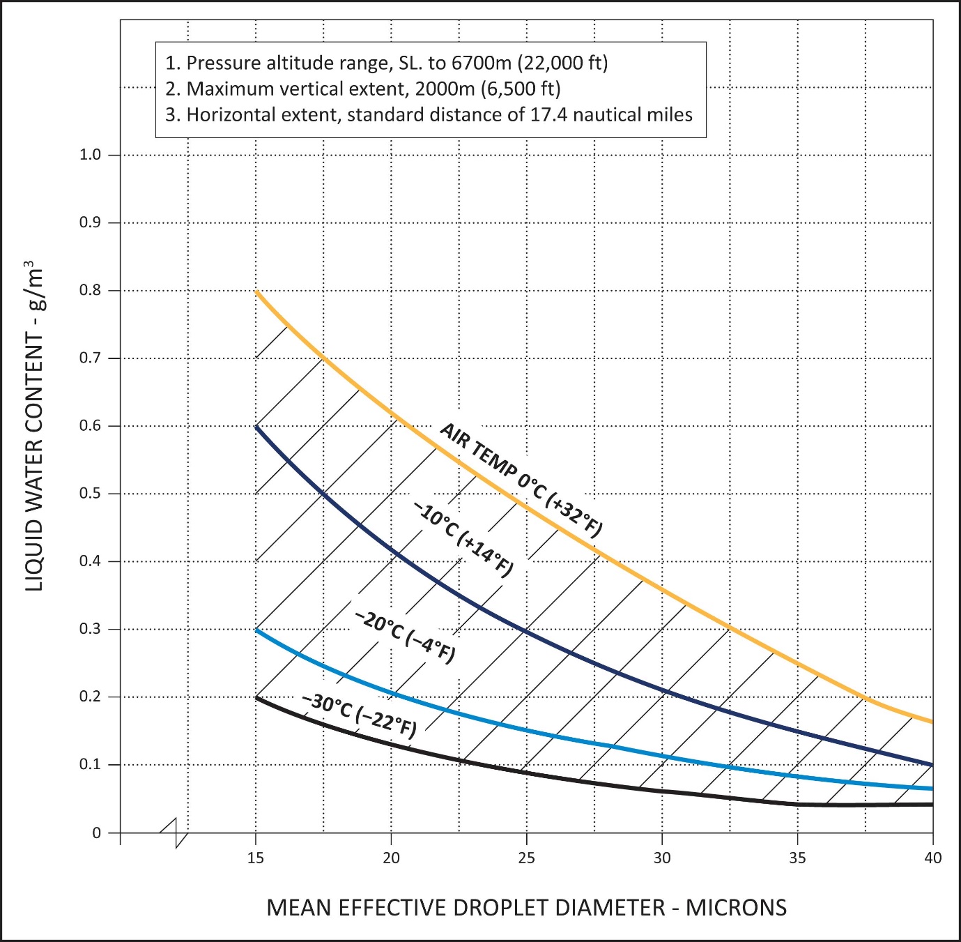
FIGURE 1
CONTINUOUS MAXIMUM (STRATIFORM CLOUDS) ATMOSPHERIC ICING CONDITIONS
LIQUID WATER CONTENT VS MEAN EFFECTIVE DROP DIAMETER
Source of data – NACA TN No. 1855, Class III - M, Continuous Maximum.
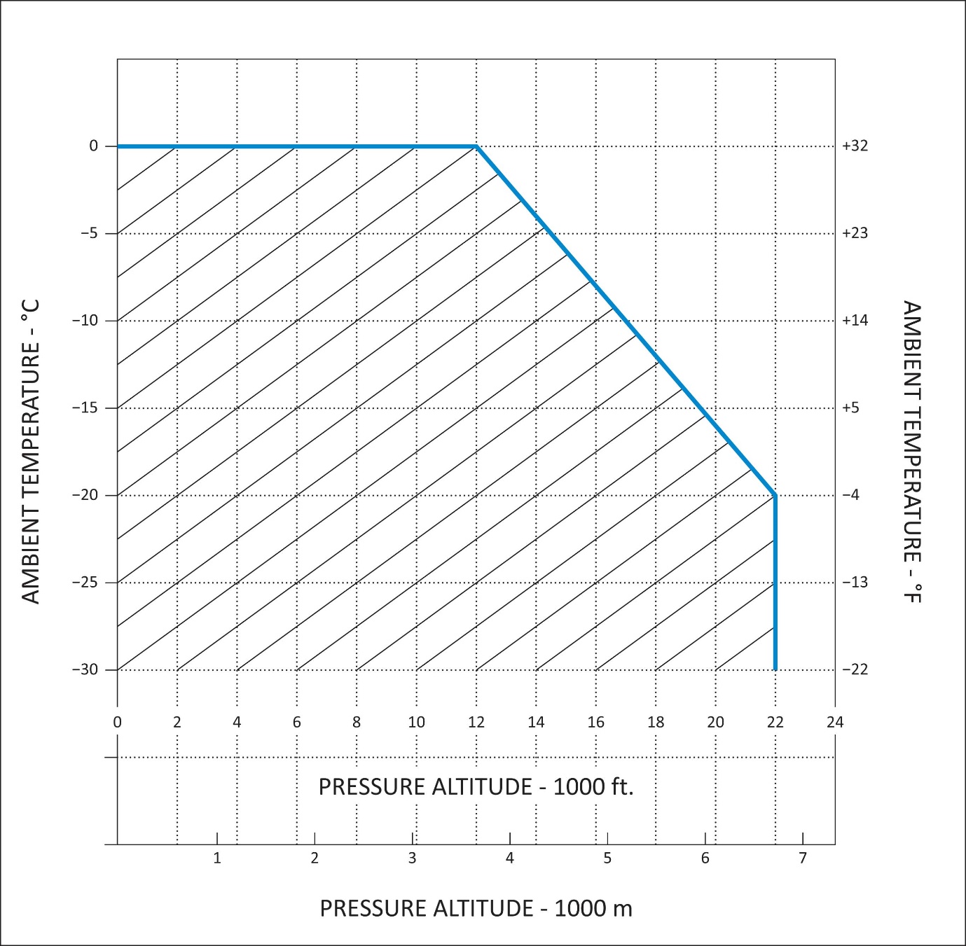
FIGURE 2
CONTINUOUS MAXIMUM (STRATIFORM CLOUDS) ATMOSPHERIC ICING CONDITIONS
AMBIENT TEMPERATURE VS PRESSURE ALTITUDE
Source of data – NACA TN No. 2569.
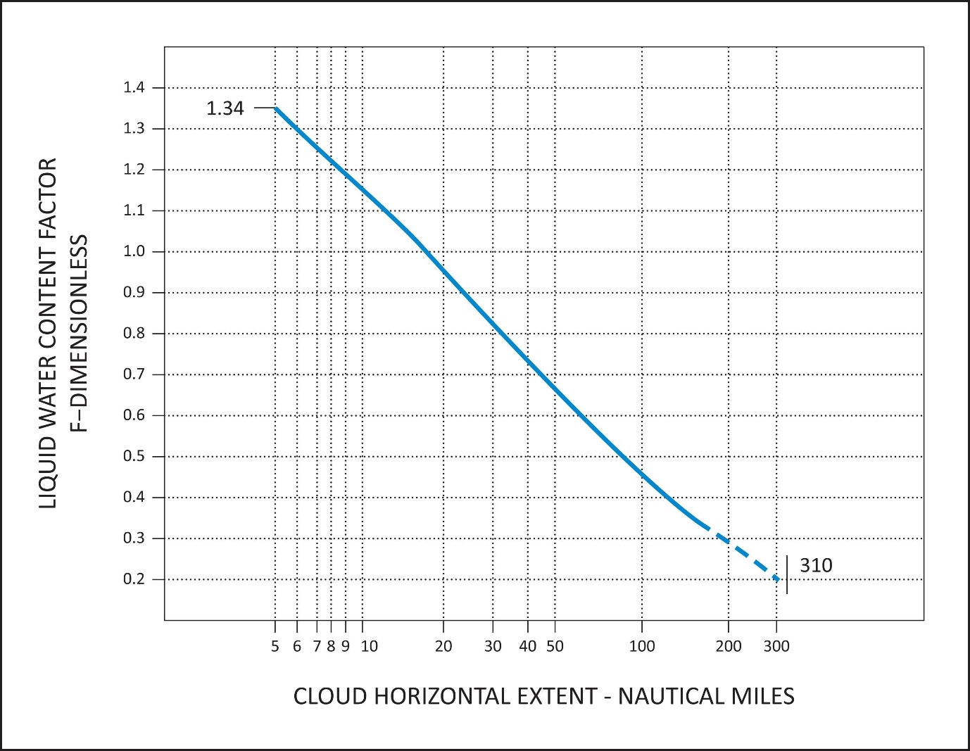
FIGURE 3
CONTINUOUS MAXIMUM (STRATIFORM CLOUDS) ATMOSPHERIC ICING CONDITIONS
LIQUID WATER CONTENT FACTOR VS CLOUD HORIZONTAL DISTANCE
Source of data – NACA TN No. 2738.
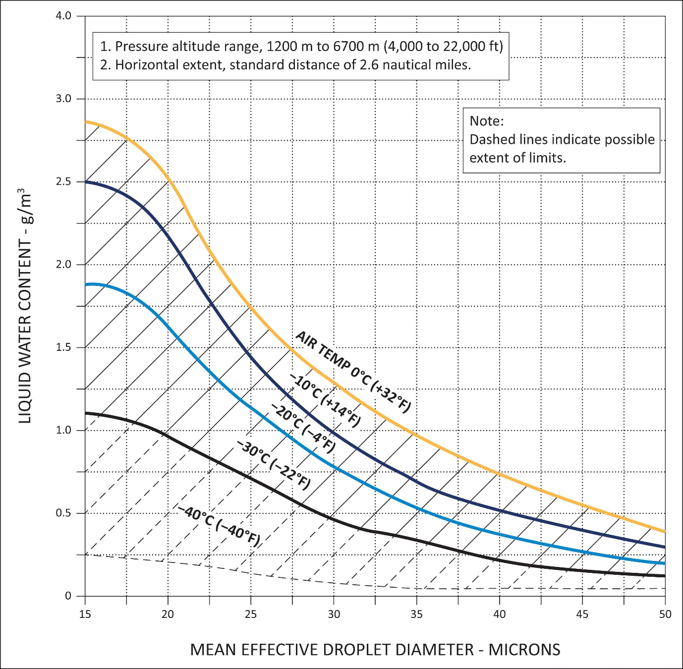
FIGURE 4
INTERMITTENT MAXIMUM (CUMULIFORM CLOUDS) ATMOSPHERIC ICING CONDITIONS
LIQUID WATER CONTENT VS MEAN EFFECTIVE DROP DIAMETER
Source of data – NACA TN No. 1855, Class II - M, Intermittent Maximum.

FIGURE 5
INTERMITTENT MAXIMUM (CUMULIFORM CLOUDS) ATMOSPHERIC ICING CONDITIONS
AMBIENT TEMPERATURE VS PRESSURE ALTITUDE
Source of data – NACA TN No. 2569.

FIGURE 6
INTERMITTENT MAXIMUM (CUMULIFORM CLOUDS) ATMOSPHERIC ICING CONDITIONS
VARIATION OF LIQUID WATER CONTENT FACTOR WITH CLOUD HORIZONTAL EXTENT
Source of data – NACA TN No. 2738.
MISCELLANEOUS EQUIPMENT
CS 29.1431 Electronic equipment
ED Decision 2003/16/RM
(a)Radio communication and navigation installations must be free from hazards in themselves, in their method of operation, and in their effects on other components, under any critical environmental conditions.
(b)Radio communication and navigation equipment, controls, and wiring must be installed so that operation of any one unit or system of units will not adversely affect the simultaneous operation of any other radio or electronic unit, or system of units, required by any applicable CS or operating rule.
CS 29.1433 Vacuum systems
ED Decision 2003/16/RM
(a)There must be means, in addition to the normal pressure relief, to automatically relieve the pressure in the discharge lines from the vacuum air pump when the delivery temperature of the air becomes unsafe.
(b)Each vacuum air system line and fitting on the discharge side of the pump that might contain flammable vapours or fluids must meet the requirements of CS 29.1183 if they are in a designated fire zone.
(c)Other vacuum air system components in designated fire zones must be at least fire resistant.
CS 29.1435 Hydraulic systems
ED Decision 2003/16/RM
(a)Design. Each hydraulic system must be designed as follows:
(1)Each element of the hydraulic system must be designed to withstand, without detrimental, permanent deformation, any structural loads that may be imposed simultaneously with the maximum operating hydraulic loads.
(2)Each element of the hydraulic system must be designed to withstand pressures sufficiently greater than those prescribed in sub-paragraph (b) to show that the system will not rupture under service conditions.
(3)There must be means to indicate the pressure in each main hydraulic power system.
(4)There must be means to ensure that no pressure in any part of the system will exceed a safe limit above the maximum operating pressure of the system, and to prevent excessive pressures resulting from any fluid volumetric change in lines likely to remain closed long enough for such a change to take place. The possibility of detrimental transient (surge) pressures during operation must be considered.
(5)Each hydraulic line, fitting, and component must be installed and supported to prevent excessive vibration and to withstand inertia loads. Each element of the installation must be protected from abrasion, corrosion, and mechanical damage.
(6)Means for providing flexibility must be used to connect points, in a hydraulic fluid line, between which relative motion or differential vibration exists.
(b)Tests. Each element of the system must be tested to a proof pressure of 1.5 times the maximum pressure to which that element will be subjected in normal operation, without failure, malfunction, or detrimental deformation of any part of the system.
(c)Fire protection. Each hydraulic system using flammable hydraulic fluid must meet the applicable requirements of CS 29.861, 29.1183, 29.1185, and 29.1189.
CS 29.1439 Protective breathing equipment
ED Decision 2003/16/RM
(a)If one or more cargo or baggage compartments are to be accessible in flight, protective breathing equipment must be available for an appropriate crew member.
(b)For protective breathing equipment required by sub-paragraph (a) or by any applicable operating rule:
(1)That equipment must be designed to protect the crew from smoke, carbon dioxide, and other harmful gases while on flight deck duty;
(2)That equipment must include:
(i)Masks covering the eyes, nose, and mouth; or
(ii)Masks covering the nose and mouth, plus accessory equipment to protect the eyes; and
(3)That equipment must supply protective oxygen of 10 minutes duration per crew member at a pressure altitude of 2438 m (8000 ft) with a respiratory minute volume of 30 litres per minute BTPD.
CS 29.1457 Cockpit voice recorders
ED Decision 2021/010/R
(See )
(a)Each cockpit voice recorder required by the applicable operating rules must be approved, and must be installed so that it will record the following:
(1)Voice communications transmitted from or received in the rotorcraft by radio.
(2)Voice communications of flight-crew members on the flight deck.
(3)Voice communications of flight-crew members on the flight deck, using the rotorcraft’s inter-phone system.
(4)Voice or audio signals identifying navigation or approach aids introduced into a headset or speaker.
(5)Voice communications of flight-crew members using the passenger loudspeaker system, if there is such a system, and if the fourth channel is available in accordance with the requirements of sub-paragraph (c)(4)(ii).
(b)The recording requirements of sub-paragraph (a)(2) may be met:
(1)By installing a cockpit-mounted area microphone, located in the best position for recording voice communications originating at the first and second pilot stations and voice communications of other crew members on the flight deck when directed to those stations; or
(2)By installing a continually energised or voice-actuated lip microphone at the first and second pilot stations.
The microphone specified in this paragraph must be so located and, if necessary, the preamplifiers and filters of the recorder must be so adjusted or supplemented, that the recorded communications are intelligible when recorded under flight cockpit noise conditions and played back. The level of intelligibility must be approved by the Agency. Repeated aural or visual playback of the record may be used in evaluating intelligibility.
(c)Each cockpit voice recorder must be installed so that the part of the communication or audio signals specified in sub-paragraph (a) obtained from the following sources is recorded on at least four separate channels:
(1)From each microphone, headset, or speaker used at the first pilot station.
(2)From each microphone, headset, or speaker used at the second pilot station.
(3)From the cockpit-mounted area microphone, or the continually energised or voice-actuated lip microphones at the first and second pilot stations.
(4)From:
(i)each microphone, headset, or speaker used at the stations for the third and fourth crew members; or
(ii)if the stations specified in sub-paragraph (c)(4)(i) are not required or if the signal at such a station is picked up by another channel, each microphone on the flight deck that is used with the passenger loudspeaker system if its signals are not picked up by another channel.
(iii)Each microphone on the flight deck that is used with the rotorcraft’s loudspeaker system, if its signals are not picked up by another channel.
No channel shall record communication or audio signals from more than one of the following sources: the first pilot station, second pilot station, cockpit-mounted area microphone, and additional crew member stations.
(d)Each cockpit voice recorder must be installed so that:
(1)(i)It receives its electrical power from the bus that provides the maximum reliability for operation of the recorder without jeopardising service to essential or emergency loads; and
(ii)It remains powered for as long as possible without jeopardising the emergency operation of the rotorcraft;
(2)There is an automatic means to stop the recording within 10 minutes after crash impact;
(3)There is an aural or visual means for pre-flight checking of the recorder for proper operation.
(4)Any single electrical failure that is external to the recorder does not disable both the cockpit voice recorder function and the flight data recorder function;
(5)There is a means for the flight crew to stop the cockpit voice recorder function upon completion of the flight in a way such that re-enabling the cockpit voice recorder function is only possible by dedicated manual action; and
(6)It has an alternate power source:
—that provides 10 minutes of electrical power to operate both the recorder and the cockpit-mounted area microphone; and
—to which the recorder and the cockpit-mounted area microphone are switched automatically in the event that all other power to the recorder is interrupted either by a normal shutdown or by any other loss of power.
(e)The container of the recording medium must be located and mounted so as to minimise the probability of the container rupturing, the recording medium being destroyed, or the underwater locating device failing as a result of any possible combinations of:
impact with the Earth’s surface;
the heat damage caused by a post-impact fire; and
immersion in water.
(f)If the cockpit voice recorder has an erasure device or function, the installation must be designed to minimise the probabilities of inadvertent operation and of actuation of the erasure device or function during crash impact.
(g)The recorder container of the cockpit voice recorder must:
(1)be bright orange;
(2)have reflective tape affixed to its external surface to facilitate locating it; and
(3)have an underwater locating device on or adjacent to the container which is secured in such a manner that they are not likely to be separated during crash impact.
[Amdt 29/7]
[Amdt 29/9]
AMC 29.1457 Cockpit Voice Recorders
ED Decision 2021/010/R
This AMC provides further guidance and acceptable means of compliance to supplement FAA AC 29-2C § AC 29.1457. § 29.1457, to meet EASA's interpretation of CS 29.1457. As such, it should be used in conjunction with the FAA AC.
1.General
The installation of a recorder with an ETSO authorisation against ETSO-C123c (or equivalent standard accepted by EASA) satisfies the approval requirement in CS 29.1457(a).
In showing compliance with CS 29.1457, the applicant should take into account EUROCAE Document ED 112A ‘MOPS for Crash-Protected Airborne Recorder Systems’ or a later revision.
‘CVR system’ designates the cockpit voice recorder (CVR) and its dedicated equipment (e.g. dedicated sensors or transducers, amplifiers, dedicated data buses, dedicated power source).
2.Automatic means to stop the recording after a crash impact
The automatic means to stop the recording within 10 minutes after a crash impact may rely on:
a.Dedicated crash impact detection sensors. In this case, negative acceleration sensors (also called ‘g-switches’) should not be used as the sole means of detecting a crash impact; or
b.The recording start-and-stop logic, provided that this start-and-stop logic stops the recording 10 ± 1 minutes after the loss of power on all engines.
3.Means for the flight crew to stop the cockpit voice recorder
The means for the flight crew to stop the cockpit voice recorder function after the completion of the flight is needed in order to preserve the recording for the purpose of investigating accidents and serious incidents. In fulfilling this requirement, it is acceptable to use circuit breakers to remove the power to the equipment. Such a means to stop the cockpit voice recorder function is not in contradiction with FAA AC 29-2C, § AC 29.1357, § 29.1357, point b.(6), because it would not be used under normal operating conditions, but only after an accident or a serious incident has occurred.
4.Power sources
The alternate power source is a power source that is different from the source(s) that normally provides (provide) power to the cockpit voice recorder. In CS 29.1457(d)(6), a ‘normal shutdown’ of power to the recorder means a commanded interruption of the power supply from the normal cockpit voice recorder power bus; for example, after the termination of a normal flight. The following applies to the installation of an alternate power source:
a.A tolerance of 1 minute on the 10 minutes minimum power requirement of CS 29.1457(d)(6) is acceptable;
b.The use of helicopter batteries or other power sources is acceptable, provided that electrical power to the essential and critical loads is not compromised;
c.If the alternate power source relies on dedicated stand-alone batteries (such as a recorder independent power supply), then these batteries should be located as close as practicable to the recorder;
d.If the cockpit voice recorder function is combined with other recording functions within the same unit, the alternate power source may also power the other recording functions; and
e.The means for performing a pre-flight check of the recorder for proper operation should include a check of the availability of the alternate power source.
5.Combination recorder
In cases where the recorder performs several recording functions, the means for pre-flight checking of the recorder for proper operation should indicate which recording functions (e.g. FDR, CVR, data-link recording, etc.) have failed.
6.Evaluation of the CVR recording
The following acceptable means of compliance with CS 29.1457(b) is provided to demonstrate that the performance of a new or modified CVR system is acceptable and that the quality of the CVR recording is acceptable. Inspections of the CVR recording that are part of the instructions for continued airworthiness (ICAs) are not within the scope of this paragraph.
a.The CVR system should be installed in accordance with the recommendations made in EUROCAE Document ED-112A, in particular:
—Chapter 2-5 ‘Equipment installation and installed performance’, and
—Part I ‘Cockpit Voice Recorder System’, Chapter I-6.1.1 ‘Interface design’, I-6.1.2 ‘Recorder Operation’ and I-6.1.3 ‘Bulk Erasure Interlocks’.
Particular attention should be given to the location of the cockpit area microphone (CAM).
ED-112A, Chapter I-6.2. ‘Equipment location’, provides guidance on this topic.
It should be noted that the CVR may record on more than four channels, and that this may help to avoid superimposition between signal sources recorded on the same CVR channel.
b.To ensure that the CVR system is properly installed, and to verify that the audio signals recorded on all channels achieve the acceptable level of quality, the applicant should conduct a flight test. The recording obtained should be evaluated to confirm an acceptable level of quality during all normal phases of flight (including taxi-out, hover, take-off, climb, cruise, descent, approach, landing, taxi-in) and autorotation. ED-112A provides guidance for testing a new CVR installation (refer to Chapter I-6.3).
c.The evaluation of the CVR recording should include:
i.the tasks described in ED-112A, Annex I-A, Chapter I-A.3;
ii.checking that the vocal signal sources are intelligible and that non-vocal alerts on headsets or speakers can be identified;
iii.checking that the levels of side tone signals (e.g. radio) and public address (PA) are adjusted so that these signals are audible and do not mask the signals from the flight crew microphones (refer to ED-112A, Part I, Chapter I-6.1.1);
iv.checking the start-and-stop function of the CVR system. The CVR should begin to operate no later than when power from sources other than from the alternate power source is available and the pre-flight checklist is started. The CVR should continue to operate either until the completion of the final post-flight checklist or until 10 minutes after power is lost on all engines; and
v.checking for the presence of any fault in the memory of the built-in test feature of the CVR, if applicable.
d.The evaluation of the CVR recording should fulfil all of the conditions below:
i.The equipment used for the CVR recording replay should meet the specifications of Chapter I-A.2 of Annex I-A of ED-112A, or a higher standard;
ii.The replay and evaluation of CVR recordings should be performed by personnel with adequate knowledge of CVR systems and aircraft operations, and who have the appropriate experience with the techniques used to evaluate recordings;
iii.The observations from the evaluation should be documented in an evaluation report. An example of an evaluation report is provided in ED-112A, Annex I-A; and
iv.The evaluation report should indicate the quality of each audio signal that is required to be recorded by CS 29.1457(c) according to defined criteria. For example, the following audio quality rating scale may be used:
GOOD:
1.When considering a vocal signal source (crew voice, radio reception, radio side tone, interphone, public address, synthetic voice in call-outs, warnings and alerts) recorded on a channel other than the CAM channel, the signal is intelligible without using any signal post-processing techniques, and no significant issue (e.g. saturation, noise, interference, or inadequate signal level of a source) affects the quality of this signal;
2.When considering non-vocal alerts recorded on a channel other than the CAM channel, the sounds are accurately identifiable in the recording without using any signal post-processing techniques, and no significant issue affects the quality of the sound recording;
3.When considering the CAM, the recording is representative of the actual ambient sound, conversations and alerts as if an observer were listening in the cockpit, and no significant issue affects the quality of the signal; and
4.No ‘medium’ or ‘major’ issue is identified on any channel (see Table 1 below for examples).
FAIR: A significant issue affects the signal source being considered. However, the related signal can still be analysed without signal post-processing, or by using signal post-processing techniques provided by standard audio analysis tools (e.g. audio level adjustment, notch filter, etc.). The severity of the identified issues is not rated higher than ‘medium’ (see Table 1 below for examples).
POOR: The signal source being considered is not intelligible or not identifiable, and this cannot be corrected even with the use of signal post-processing techniques. The severity of the identified issues is not necessarily rated as ‘major’; it may also be rated as ‘medium’ depending on the consequence for the required signal sources (see Table 1 below for examples); and
v.the audio quality rating of a CVR channel required by CS 29.1457(c) should be the same as the worst audio quality rating among the signal sources to be recorded on this channel.
e.The performance of the CVR system should be considered acceptable by the applicant only if, for none of the signal sources required by CS 29.1457(c) or by the applicable operating rules, the audio quality of the recording was rated as ‘POOR’. In addition, if the CVR system is part of a new aircraft type, the performance of the CVR system should be considered acceptable by the applicant only if for all of the signal sources required by CS 25.1457(c) and by the applicable operating rules, the quality of the audio recording was rated as ‘GOOD’.
Table 1: Examples of issues affecting a signal source and of the associated severity
| Examples of issues |
MAJOR — leading to a ‘POOR’ rating for the affected signal | —One or more warnings or call-outs are not recorded —Uncommanded interruption of the CAM signal —Unexplained variation of the CAM dynamic range —Hot-microphone function not operative —CVR time code not available —CAM saturation (due to low-frequency vibration) —Radio side tone is missing —One required signal source is missing from the recording (e.g. one microphone signal not recorded) —Poor intelligibility of one microphone source (e.g. speech through oxygen mask microphone) —Quasi-permanent physical saturation of the CAM due to its excessive sensitivity —Quasi-permanent electrical saturation of a CVR channel —Mechanical and/or electrical interference making the transcription of signals difficult or impossible —Insufficient CAM sensitivity —Fault in the start/stop sequence |
MEDIUM — leading to a ‘POOR’ or ‘FAIR’ rating for the affected signals, depending on the duration and the occurrence rate of the issues | —Inappropriate level balance between signal sources on a CVR channel, which results in a signal source masking other signal sources —Electrical interference caused by either the aircraft or the recorder power supply —Low dynamic range of the recording on a CVR channel —Low recording level of alert and/or call-out —Oversensitivity of the CAM line* to electromagnetic interference in the HF, UHF or EHF domain (Wi-Fi, GSM, 5G, etc.) —Oversensitivity of the CAM line* to electrostatic discharge (ESD) phenomena —Oversensitivity of the CAM to air flow or air-conditioning noise (bleed air) —Phasing anomaly between CVR channels —Side tone recorded with low level —Transitory saturation |
*CAM line: microphone+control or preamplifier unit+wiring to the CVR
7.Instructions for continued airworthiness (ICAs)
When developing the ICAs for the CVR system, required by CS 29.1529 and its Appendix A, the applicant should address all failures that may affect the correct functioning of the CVR system or the quality of the recorded audio signals.
Examples of failures (indicative and non-exhaustive list):
The loss of the recording function or of the acquisition function of the CVR.
Any communication or audio signal (required by CS 29.1457(c) or by the applicable air operations regulations) is missing, or is recorded with an audio quality that is rated ‘POOR’ (refer to the example of audio quality rating provided in Section 6 of this AMC).
The failure of a sensor, transducer or amplifier dedicated to the CVR system (e.g. failure of the cockpit area microphone).
The failure of a means to facilitate the finding of the CVR recording medium after an accident (e.g. an underwater locating device or an emergency locator transmitter attached to the recorder).
The failure of any power source dedicated to the CVR (e.g. dedicated battery).
The failure of the start-and-stop function.
The failure of a means to detect a crash impact (for the purpose of stopping the recording after a crash impact, or for the purpose of deploying the recorder if it is deployable).
[Amdt 29/7]
[Amdt 29/9]
CS 29.1459 Flight data recorders
ED Decision 2021/010/R
(See )
(a)Each flight data recorder required by the applicable operating rules must be approved and must be installed so that:
(1)It is supplied with airspeed, altitude, and directional data obtained from sources that meet the accuracy requirements of CS 29.1323, 29.1325, and 29.1327, as applicable;
(2)The vertical acceleration sensor is rigidly attached, and located longitudinally within the approved centre of gravity limits of the rotorcraft;
(3)(i)It receives its electrical power from the bus that provides the maximum reliability for operation of the flight recorder without jeopardising service to essential or emergency loads; and
(ii)It remains powered for as long as possible without jeopardising the emergency operation of the rotorcraft;
(4)There is an aural or visual means for pre-flight checking of the recorder for proper recording of data in the storage medium;
(5)Except for recorders powered solely by the engine-driven electrical generator system, there is an automatic means to stop the recording within 10 minutes after any crash impact;
(6)If the cockpit voice recorder function is also performed by the recorder and no other recorder is installed on board the rotorcraft, any single electrical failure that is external to the recorder does not disable both the cockpit voice recorder function and the flight data recorder function; and
(7)If another recorder is installed on board the rotorcraft to perform the cockpit voice recorder function, any single electrical failure that is external to the recorder dedicated to the flight data recorder function does not disable both the recorders.
(b)The container of the recording medium must be located and mounted so as to minimise the probability of the container rupturing, the recording medium being destroyed, or the underwater locating device failing, as a result of any possible combinations of:
impact with the Earth’s surface;
the heat damage caused by post-impact fire; and
immersion in water.
(c)A correlation must be established between the flight data recorder readings of airspeed, altitude, and heading and the corresponding readings (taking into account correction factors) of the first pilot’s instruments. This correlation must cover the airspeed range over which the aircraft is to be operated, the range of altitude to which the aircraft is limited, and 360° of heading. Correlation may be established on the ground as appropriate.
(d)The container of the flight data recorder must comply with the specifications in CS 29.1457(g) that are applicable to the container of the cockpit voice recorder.
[Amdt No: 29/7]
[Amdt No: 29/9]
AMC 29.1459 Flight Data Recorders
ED Decision 2021/010/R
This AMC provides further guidance and acceptable means of compliance to supplement FAA AC 29-2C § AC 29.1459. § 29.1459, to meet EASA's interpretation of CS 29.1459. As such, it should be used in conjunction with the FAA AC.
1.General
The installation of a recorder with an ETSO authorisation against ETSO-C124 (or equivalent standard accepted by EASA) satisfies the approval requirement in CS 29.1459(a).
In showing compliance with CS 29.1459, the applicant should take into account EUROCAE Document ED-112A ‘MOPS for Crash-Protected Airborne Recorder Systems’ or a later revision.
’FDR system’ designates the flight data recorder (FDR) and its dedicated equipment. It may include the following items as appropriate to the aircraft:
a.Equipment necessary to:
i.acquire and process analogue and digital sensor signals;
ii.store the recorded data in a crash-survivable recording medium; and
iii.when necessary, support dedicated sensors.
b.Digital data buses and/or networks providing communications between the elements of the system.
2.Automatic means to stop the recording after a crash impact
Refer to the Section of AMC 29.1457 titled ‘Automatic means to stop the recording after a crash impact’.
3.Combination recorder
Refer to the Section of AMC 29.1457 titled ‘Combination recorder’.
4.Instructions for continued airworthiness (ICAs)
When developing the ICAs for the FDR system, required by CS 29.1529 and its Appendix A, the applicant should address all failures that may affect the correct functioning of the FDR system or the quality of the recorded data.
Examples of failures (indicative and non-exhaustive list):
The loss of the recording function or of the acquisition function of the FDR.
Any parameter (required by CS 29.1459(a)(1) or by the applicable air operations regulations) is missing or is not correctly recorded.
The failure of a sensor dedicated to the FDR system.
The failure of a means to facilitate the finding of the FDR recording medium after an accident (e.g. an underwater locating device or an emergency locator transmitter attached to the recorder).
The failure of the start-and-stop function.
The failure of a means to detect a crash impact (for the purpose of stopping the recording after a crash impact, or for the purpose of deploying the recorder if it is deployable).
In addition, the ICAs should include the following items, unless the applicant shows that this is not applicable:
Calibration checks of the parameters from sensors dedicated to the FDR to verify the accuracy of these parameters; and
FDR decoding documentation:
i.Definitions
FDR decoding documentation: a document that presents the information necessary to retrieve the raw binary data of an FDR data file and convert it into engineering units and textual interpretations.
Fixed frame recording format: a recording format organised in frames and subframes of a fixed length and that are recorded chronologically. ARINC specifications 573 and 717 provide an example of a fixed frame recording format.
Variable frame recording format: a recording format based on recording frames which are individually identified and time stamped, so that their order in the recording file is not important. ARINC specification 767 provides an example of variable frame recording format.
ii.Content of the FDR decoding documentation
The FDR decoding documentation should at least contain information on the following:
—the aircraft make and model;
—the document modification date and time;
—in the case of a fixed-frame recording format:
—the sync pattern sequence;
—the number of bits per word, of words per subframe and of subframes per frame; and
—the time duration of a subframe;
—in the case of a variable-frame recording format, the list of frames, and for each frame:
—its identification;
—information on whether the frame is scheduled or event triggered;
—the recording rate (for a scheduled frame);
—the frame event condition (for an event-triggered frame); and
—the list of parameters, by order of recording;
—for every parameter:
—the identification: name (and mnemonic code or other identification if applicable);
—the sign convention and the units of the converted values (if applicable);
—the location of each parameter component in the data frame;
—instructions and equations to assemble the parameter components and convert the raw binary values into engineering units (if applicable); and
—the conversion to text or the discrete decipher logic (if applicable).
iii.Format of the FDR decoding documentation
The FDR decoding documentation should:
—be provided in an electronic format;
—contain all the information described in paragraph (ii) above; and
—comply with the standard of ARINC Specification 647A or a later equivalent industry standard.
[Amdt 29/7]
[Amdt 29/9]
CS 29.1460 Data link recorders
ED Decision 2021/010/R
(See )
(a)Each recorder performing the data link recording function required by the operating rules must be approved and must be installed so that it will record the data link communication messages related to air traffic service (ATS) communications to and from the rotorcraft.
(b)Each data link recorder must be installed so that:
(1)(i)it receives its electrical power from the bus that provides the maximum reliability for the operation of the recorder without jeopardising service to essential or emergency loads; and
(1)(ii)it remains powered for as long as possible without jeopardising the emergency operation of the rotorcraft; and
(2)there is an aural or visual means for pre-flight checking of the recorder for the proper recording of data in the storage medium.
(c)The container of the recording medium must be located and mounted so as to minimise the probability of the container rupturing, the recording medium being destroyed, or the underwater locating device failing as a result of any possible combinations of:
impact with the Earth’s surface;
the heat damage caused by a post-impact fire; and
immersion in water.
(d)The container of the data link recorder must comply with the specifications applicable to the container of the cockpit voice recorder in CS 29.1457(g).
[Amdt 29/9]
AMC 29.1460 Data link recorders
ED Decision 2021/010/R
1.General
The installation of a recorder with an ETSO authorisation against ETSO-C177 (or equivalent standard accepted by EASA) satisfies the approval requirement in CS 29.1460(a).
In showing compliance with CS 29.1460, the applicant should take into account EUROCAE Document ED-112A, ‘Minimum Operational Performance Specification for Crash Protected Airborne Recorder Systems’, dated September 2013, or standard later revision.
‘DLR system’ designates the data link recorder (DLR) and its dedicated equipment. It may include the following items as appropriate to the aircraft:
a.A crash-protected recorder.
b.Digital interface equipment suitable for converting a data link communication message into a format which is to be recorded.
c.Digital data buses and/or networks providing communications between the elements of the system.
The data link recording function may be performed by:
a.a cockpit voice recorder;
b.a flight data recorder;
c.a flight data and cockpit voice combination recorder; or
d.a dedicated data link recorder.
2.Combination recorders
Refer to the paragraph of AMC 29.1457 titled ‘Combination recorder’.
3.Recorded data
The recorded data should be sufficient to allow investigators, in the framework of an accident or incident investigation, to accurately reconstruct the sequence of data link communications between the aircraft and the air traffic service units, other aircraft and other entities. For this purpose, the data link recording should comply with the following:
a.EUROCAE Document ED-93, ‘Minimum Aviation System Performance Specification for CNS/ATM Message Recording Systems’, Section 2.3.1, ‘Choice of recording points’, and Section 2.3.2, ‘Choice of data to be recorded on board the aircraft’; and
b.EUROCAE Document ED-112A, ‘Minimum Operational Performance Specification for Crash Protected Airborne Recorder Systems’ (dated September 2013), Part IV, Chapter IV-2, Section IV-2.1.6, ‘Data to be recorded’.
4.Instructions for continued airworthiness (ICAs)
When developing the ICAs for the DLR system, required by CS 29.1529 and its Appendix A, the applicant should address all failures that may affect the correct functioning of the DLR system or the integrity of the recorded information.
Examples of failures (indicative and non-exhaustive list):
The loss of the recording function or of the acquisition function of the DLR.
Part of the data link communication (required by CS 29.1460(a) or by the Air Operations Regulation) is missing or is corrupted.
The failure of a means to facilitate the finding of the DLR recording medium after an accident (e.g. an underwater locating device or an emergency locator transmitter attached to the recorder).
The failure of a means to detect a crash impact (for the purpose of stopping the recording after a crash impact, or for the purpose of deploying the recorder if it is deployable).
In addition, the ICAs should include the following, unless the applicant shows that this is not applicable:
Documentation to perform the following:
i.convert the recorded data back to the original format of the data link communication messages;
ii.retrieve the time and the priority of each recorded message; and
iii.correlate the recorded messages with the FDR and CVR recordings.
[Amdt 29/9]
CS 29.1461 Equipment containing high energy rotors
ED Decision 2003/16/RM
(a)Equipment containing high energy rotors must meet sub-paragraphs (b), (c), or (d).
(b)High energy rotors contained in equipment must be able to withstand damage caused by malfunctions, vibration, abnormal speeds, and abnormal temperatures. In addition:
(1)Auxiliary rotor cases must be able to contain damage caused by the failure of high energy rotor blades; and
(2)Equipment control devices, systems, and instrumentation must reasonably ensure that no operating limitations affecting the integrity of high energy rotors will be exceeded in service.
(c)It must be shown by test that equipment containing high energy rotors can contain any failure of a high energy rotor that occurs at the highest speed obtainable with the normal speed control devices inoperative.
(d)Equipment containing high energy rotors must be located where rotor failure will neither endanger the occupants nor adversely affect continued safe flight.
CS 29.1465 Vibration Health Monitoring
ED Decision 2012/022/R
(a)If certification of a rotorcraft with vibration health monitoring of the rotors and/or rotor drive systems is requested by the applicant, then the design and performance of an installed system must provide a reliable means of early detection for the identified failure modes being monitored.
(b)If a vibration health monitoring system of the rotors and/or rotor drive systems is required by the applicable operating rules, then the design and performance of the vibration health monitoring system must, in addition, meet the requirements of this paragraph.
(1)A safety analysis must be used to identify all component failure modes that could prevent continued safe flight or safe landing, for which vibration health monitoring could provide a reliable means of early detection;
(2)All typical VHM indicators and signal processing techniques should be considered in the VHM System design;
(3)Vibration health monitoring must be provided as identified in subparagraph (1) and (2), unless other means of health monitoring can be substantiated.
[Amdt 29/3]