
Filters
AMC1 29.1465 Vibration health monitoring
ED Decision 2024/009/R
(a)Introduction
(1)VHM systems are typically intended at increasing the likelihood of detection of dynamic component incipient faults in the rotors and rotor drive systems whose progression, if undetected, could prevent continued safe flight or safe landing.
(2)A VHM system typically features airborne and ground segments which, depending on the design and intended functions of the system, may include vibration sensors and the associated wiring, airborne electronic hardware for data acquisition and processing, and means for the storage, transfer and display of data. For the purpose of this AMC, the associated instructions for operation of the system should also be considered as part of the VHM system.
(3)A VHM system may be used to fulfil a number of functions (VHM applications), each including a range of components and their associated kinds of damage or degradation being monitored, which may eventually, if undetected, lead to a failure. The three main VHM system purposes or kinds of VHM applications considered within the scope of this AMC are the following:
(i)Supplementary information (‘no hazard/no credit basis’)
VHM system applications providing ‘supplementary information’ are considered those that monitor rotorcraft components whose failure is adequately mitigated by other compensating provisions specified and evaluated as part of the certification of the product. Therefore, they are not required as part of the minimum type design definition to be certified in accordance with CS-29. When such VHM system is installed, approval of the installation with applicable certification specifications is required, nonetheless.
(ii)In support of compliance with an operational regulation (i.e. currently referring to Regulation (EU) No 965/2012)
VHM system applications in support of compliance with an operational regulation also monitor rotorcraft components whose failure is adequately mitigated by other compensating provisions. However, they provide an additional safety benefit that is required for certain kinds of rotorcraft operations that typically entail greater risk (e.g. offshore operations). Following the approach described in this AMC is intended to ensure that such VHM applications ensure such additional safety benefit by means of an increased likelihood of early detection of incipient failures.
(iii)Airworthiness-related purposes (credit applications)
VHM systems with airworthiness-related purposes, also referred to as credit applications or VHM applications for credit, are also addressed in this AMC and in GM1 29.1465. Such VHM system applications may be relied upon:
(A)to minimise the likelihood of occurrence of hazardous or catastrophic failures of the rotor and/or rotor drive systems components, as identified in the design assessments of CS 29.547(b) and/or CS 29.917(b),
(B)to complement or replace continuing airworthiness tasks18 or flight manual procedures19 required to ensure safe operation of the rotorcraft, and/or
(C)used as approved equivalent means, in accordance with CS 29.571/573, to prevent catastrophic failures as a result of fatigue cracking.
The applicant should specify the applications to be covered by the VHM system and the components involved in each application.
(4)The purpose of this AMC is to provide an acceptable means of compliance for the design and certification of VHM applications. Designing a VHM system and demonstrating its compliance with CS 29.1465 in accordance with this AMC is expected to achieve the required performance together with acceptable levels of system integrity and reliability for the system to adequately fulfil its intended functions.
Note: FAA AC 29-2C Miscellaneous Guidance (MG)15, which addresses the use of health and usage monitoring systems (HUMS) in maintenance, is no longer recognised for the purpose of VHM system certification within the EASA framework. The scope of MG 15 for what refers to VHM systems is now addressed by this AMC. For HUMS other than VHM, applicants should consider this AMC as relevant guidance, although sections may require adaptations.
(b)Explanation
(1)CS 29.1465 does not mandate the fitment of VHM systems. However, if a VHM system is installed in one of the following scenarios, then compliance with CS 29.1465 is required when:
(i)as per (a)(3)(iii), the VHM system is required to perform specific functions relevant to ensure the airworthiness of the rotorcraft (i.e. credit applications);
(ii)as per (a)(3)(ii), the VHM system is used as a means of demonstrating compliance with an operational regulation requiring helicopters to be fitted with a VHM system and operators of such helicopters to implement procedures covering data collection, analysis and determination of condition.
(2)Systems installed for supplementary information purposes, described in (a)(3)(i) above, do not need to comply with CS 29.1465. In addition, the VHM system’s documentation for operators, including the ICA (if any) or other maintenance instructions, should clearly:
(i)state the purposes for which use of the system is approved,
(ii)specify that no safety benefit is obtained from the installation of the system, and
(iii)ensure that no complete or partial replacement of other existing continuing airworthiness tasks, upon which the airworthiness of the rotorcraft depends, may result.
However, the applicant may request compliance with CS 29.1465 on a voluntary basis; for example, to meet a customer requirement or a company objective. This is a recommended approach in order to ensure a minimum standard and state of the art in VHM systems.
In any case, the applicant should ensure that the installation of any VHM system does not significantly interfere with the air operations and/or continuing airworthiness of the rotorcraft.
(3)CS 29.1465(a) specifies that the design and performance of a VHM system should be appropriate in order to provide reliable means of early detection for the identified failure modes being monitored for the intended applications of the system. This specification applies to any VHM system for which compliance with CS 29.1465 is requested. This AMC provides specific objectives and considerations for VHM systems to be approved in support of compliance with an operational regulation and for systems with credit applications.
(4)In addition, where a VHM system is used as a means of demonstrating compliance with an operational regulation, CS 29.1465(b) is also applicable. This paragraph aims to ensure that the scope of the monitoring performed by the VHM system, and the monitoring techniques used provide an increased likelihood of early detection of incipient failures.
(5)The safety analysis required by CS 29.1465(b)(1) is limited to the mechanical systems being monitored by VHM. Since rotors and/or rotor drive systems are typically addressed, the design assessments performed in compliance with CS 29.547(b) and CS 29.917(b), respectively, can be used as a basis for this purpose. All component failure modes that could prevent continued safe flight or safe landing (catastrophic and hazardous failures) and for which VHM could provide a reliable means of early detection must be identified. Previous experience together with the guidance in this AMC and GM1 29.1465 should be used to determine failure modes that could benefit from VHM and the applicable techniques that can produce reliable indications in case of damage or degradation.
(6)CS 29.1465(b)(2) requires the design and performance of the VHM system to consider indicators and processing techniques used on typical existing VHM applications for similar components. A non-exhaustive list is provided in Table 1 of GM1 29.1465. Applicants choosing to comply with CS 29.1465 for VHM systems installed on a ‘no hazard/no credit basis’ are recommended to take this subparagraph into consideration as part of their compliance demonstration.
(7)CS 29.1465(b)(3) states that VHM must be provided as identified in subparagraphs (b)(1) and (b)(2) unless other means of health monitoring can be substantiated. For many failure modes there may be other compensating provisions which can provide protection against the risk of premature failure. In such cases, it is expected that VHM will provide an added benefit by increasing the likelihood of early detection. However, the implementation of VHM for a given component or failure mode will not be necessary if no safety benefit may be established from it. For the purpose of establishing the safety benefit of implementing VHM, the applicant should also consider the capability that the system may achieve after introduction into service through the gathering of data from the fleet and the development of improved indicators and alerting criteria.
(c)Procedure
Any VHM system to be installed in a rotorcraft must, regardless of its intended applications, comply with the applicable certification basis. In accordance with CS 29.1301, the VHM system must be of a kind and design appropriate to its intended function and must function properly when installed. For this purpose, the design considerations listed in GM1 29.1465(b) may be taken into account.
In addition, for any VHM system to be approved in support of compliance with an operational regulation and/or to fulfil an airworthiness-related function, as stated in (b)(1) above, compliance with CS 29.1465 is required.
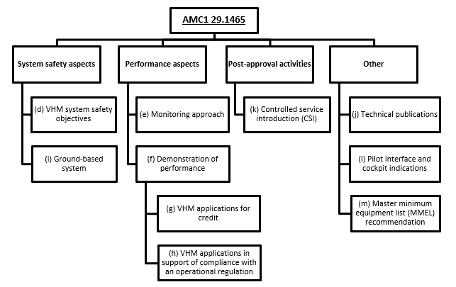
This AMC addresses the compliance demonstration for VHM systems installed for these purposes as described in Figure 1 below.
Figure 1 Structure of AMC1 29.1465 grouped by compliance demonstration aspects
(d)VHM system safety objectives
(1)Scope
This section describes an acceptable approach to determine the VHM system failure severity and the identification of its corresponding safety objectives, complementing CS 29.1309 and associated guidance. As previously stated, VHM systems typically consist of airborne and ground segments, and this section shall be considered as applicable for the end-to-end system for the purpose of establishing its safety objectives. The compliance demonstration should then be completed in accordance with the following:
(i)The compliance demonstration activities to be followed as part of the VHM system compliance demonstration for airborne equipment and the associated installation are the same as for any other airborne equipment.
(ii)For the ground segment, paragraph (i) of this AMC provides details regarding the determination of compliance with the corresponding system safety objectives considering that CS-29 certification specifications are not directly applicable. This section also considers that the ground segment of VHM systems typically contains COTS hardware and software.
(2)Evaluation of the VHM system
Safety assessment methods should be applied to identify the potential failures of the components being monitored and of the VHM system functions and determine their severity. Since establishing the severity of VHM system failures may be subject to interpretation, the following considerations20 are provided in support of the evaluation of the severity of the VHM system failures. These considerations apply to any loss of function and/or malfunction of the VHM system that may prevent detection of a potential incipient failure before it progresses to its ultimate failure consequences:
(i)Based on the intended function of the VHM system, the applicant should consider that, for the purpose of establishing the safety objectives to be achieved, the severity of any such VHM system failure impacting applications for credit or in support of compliance with an operational regulation should not be lower than minor.
(ii)When the VHM system features applications for credit, the applicant should:
—identify possible degraded conditions (i.e. types of damage or degradation) to be monitored,
—evaluate the severity of their ultimate failure consequences, when undetected, and
—assign to the VHM system adequate safety objectives.
When assigning the VHM system safety objectives, the applicant may consider alleviating factors, described in (3) below. These are elements that reduce the extent of reliance on the VHM system towards ensuring the airworthiness of the rotorcraft, which typically include:
—mitigating actions, described in (3)(i) below, and/or
—the probability of occurrence of any possible preceding degraded conditions, described in (3)(ii) below.
Following the evaluation of these alleviating factors, the applicant may propose system safety objectives for VHM systems featuring applications for credit in accordance with the process described in (4) below.
(3)Alleviating factors
(i)Mitigating actions
This term refers to continuing airworthiness tasks including maintenance tasks, and inspections, as well as alternative means of monitoring that are fully independent from VHM. These may be implemented and demonstrated to adequately monitor the affected part(s) in parallel with VHM monitoring in support of preventing the mechanical failure addressed by the credit application.
Any mitigating action implemented in parallel to a VHM application for credit should be demonstrated to be capable of detecting the mechanical conditions that may indicate the presence of damage or degradation. The applicant should consider the detection capability, the time between possible detection and ultimate failure; as well as, when applicable, the periodicity of the mitigating actions. It should be demonstrated that:
(A)the minimum mitigating actions provide a minimum of one opportunity to detect the degrading condition of the part. This should be understood as the completion of one inspection or one review of any indications from alternative monitoring means, within an interval in which they are justified to clearly detect the incipient failure;
(B)alternatively, extended mitigating actions, which should ensure two or more opportunities of detection, may be demonstrated to justify a greater alleviation.
For this evaluation, the applicant should consider:
—failure progression characteristics taking into account the considerations provided in (g)(2)(i)(A); and
—the detection capability of the mitigating action in question, derived from service data and/or test results, to establish the point at which the incipient failure will be detected.
(ii)The probability of occurrence of any possible preceding degraded conditions
Typically, VHM systems rely on the principle of a degraded condition preceding the failure generating a mechanical response, which can be detected by the vibration signals acquired and processed. These early signs of damage or degradation typically initiate naturally due to the normal operation of dynamic components and particularly in the presence of minor defects (e.g. indents, micropits, etc.) or slightly altered operating conditions (e.g. misalignment, wear, etc.). Such preceding degraded conditions usually develops by means of continuous operation, potentially becoming detectable at a certain point, while, if not detected, it may eventually lead to an ultimate failure.
The applicant may choose to justify that the likelihood of initiation of any possible degraded condition that may progress and ultimately lead to a failure is sufficiently low to support an alleviation of the VHM system safety objectives. For this purpose, the applicant should establish that the probability of occurrence of any preceding degraded condition is no greater than:
—1E-05 per flight hour for catastrophic failures,
—1E-04 per flight hour for hazardous failures, and
—1E-03 per flight hour for major failures.
(A)As part of the determination of the probability of occurrence, the applicant should:
(a)identify the degraded conditions from which it is considered probable that such a failure may develop within the exposure time of the affected parts to operation. For this purpose, the applicant should rely on all available data, including but not limited to service experience, incidents and accidents, literature review and applicable test data. In addition, the applicant should consider that dedicated testing may be needed in support of confirming whether specific degraded conditions are likely to lead to a failure;
(b)determine whether a safety factor should be taken into account for uncertainties and/or to compensate for limited data. Uncertainties may include instances where service experience from similar designs is used or when there is a need to improve the confidence in the applicability of the probability of occurrence determined for the complete life of the product. Compensation for limited data may be needed when directly applicable service experience is only just enough to demonstrate the target probability of occurrence or when not all environments/types of operation are covered by the available data;
(c)consider the effects of intrinsic flaws that may be present in the part or assembly. Only those flaws that would not be detected by quality controls and/or acceptance tests need to be taken into account;
(d)detail the parameters and controls (including design, manufacturing, quality, assembly, handling, and maintenance practices) of the affected part that support the determination of the low probability of occurrence of any preceding degraded condition demonstrated at the time of the approval. This should confirm that this probability is valid and that it will not increase during the life of the product. The applicant should describe these parameters and controls and justify their adequacy based on service experience, state-of-the-art practices and safety margins;
(e)take into consideration any changes to the replacement, inspection or overhaul intervals of the affected components that may be implemented within the period used to gather the necessary service experience for this demonstration. This should verify that none of these changes may impact the validity of the probability of occurrence justified. For example, the affected part may be replaced at a certain interval, which in turn would affect its exposure to operation in the presence of defects. As a result, the data being considered for this evaluation may not be conservative if the affected part is planned to be replaced at a greater interval following introduction of VHM.
(B)In order to determine the level of alleviation that may be proposed, the applicant should evaluate the data supporting the determination of this low probability of occurrence and identify whether:
(a)it relies on directly applicable service experience. This would require sufficient operating time to be accumulated and the necessary inspections, investigations and analyses to be performed on the in-service fleet. This approach would generally result in high confidence in the probability of occurrence derived;
(b)alternatively, it mainly uses service experience from similar designs. The use of service experience from similar designs should be justified as applicable considering the design characteristics, manufacturing and quality controls, and operating conditions. This approach would generally result in lower confidence in the probability of occurrence derived.
(4)Identification of the VHM system safety objectives
As described in (2) the applicant may take into consideration alleviating factors from those described in (3) to determine the VHM system safety objectives. When this approach is taken, the process described in this section supports the identification of the corresponding safety objectives.
The applicant should assess the complete set of alleviating factors featured by the VHM application for credit, as described in (3). Based on this, the applicant may identify which case from those described in Figure 2 below corresponds to the VHM system for which approval is sought.
Based on the case identified in Figure 2 and the severity of the undetected mechanical failure, the applicant should identify the safety objectives. The quantitative (numerical probabilities) and qualitative (FDAL) objectives are provided in Figures 3 and 4, respectively. Examples of the use of Figures 2, 3 and 4 below are provided in GM1 29.1465(c).
Figure 2: Identification of cases for alleviation of the VHM system safety objectives based on mitigating actions and probability of occurrence of any possible preceding degraded condition

Figure 3: Quantitative safety objectives identified as a function of the severity of the undetected mechanical failure and the case for alleviation of the VHM system safety objectives from Figure 2

When the alleviating factors identified for a particular VHM application fall between cases (i.e. between Cases 1 and 2 or between Cases 2 and 3), the applicant may propose quantitative safety objectives commensurate with the Cases between which it sits. For example, this occurs when the probability of occurrence is established with high confidence (as specified in (3)(ii)(B)(a)), but at a probability below the values specified in (3)(ii) (i.e. equivalent to something in between Cases 2 and 3). Examples of how this can be approached are provided in Figures 4 to 6 in GM1 29.1465(c).
Figure 4: Qualitative safety objectives (FDAL) identified as a function of the severity of the undetected mechanical failure and the case for alleviation of the VHM system safety objectives from Figure 2

The safety objectives specified in Figures 3 and 4 should be allocated to any loss of function and/or malfunction of the VHM system that may prevent detection of a potential incipient failure before it progresses to its ultimate failure consequences. This typically includes failures such as undetected loss of monitoring and/or undetected erroneous data, which may remain dormant for intervals that could preclude at least one opportunity of detection by VHM.
(5)Implementation of safety requirements
The safety objectives to be met by the VHM system should establish the confidence that development errors have been minimised with an appropriate level of rigour, and system failure rates have been reduced to acceptable levels in accordance with CS 29.1309. EUROCAE ED-79B / SAE ARP 4754B is recognised as providing additional guidelines for establishing both safety assessment and development assurance processes. Further guidance regarding expected validation and verification activities are provided in paragraphs (f), (g), (h) and (i).
(e)Monitoring approach
The monitoring approach of a VHM application includes all the elements of the VHM system that ensure that its objectives are fulfilled. It encompasses any element of the VHM system design, installation and documentation which are defined in support of achieving the demonstrated fault detection performance.
The signal processing techniques, condition indicators and alerting criteria represent key elements of the monitoring approach, whose suitability is to be substantiated as part of the fault detection performance demonstration. In addition, other relevant elements focus on ensuring that VHM data is acquired, and indications are provided at appropriate intervals, as well as on allowing for the management of these indications to determine the condition of the monitored components. These are also important to ensure that the targeted fault detection performance is achieved. To ensure that a robust monitoring approach is defined in support of consistently achieving the necessary performance, the following elements should be considered:
(1)Signal acquisition
The acquisition cycle should be designed in such a way that all selected components and their failures are adequately monitored at an appropriate frequency irrespective of any interruptions in the cycle due to the operational profile. For this purpose, the sensitivity, dynamic range and bandwidth needs of the signal acquisition of each monitored component should be taken into consideration. Furthermore, the applicant should minimise the impact on the indicator values from the operating conditions in which the vibration signals are acquired.
The acquisition cycle should be justified as appropriate for each of the intended VHM applications of the system. Based on the acquisition cycle and the requirements of the applications of the VHM system, the applicant should define a recommended and a minimum frequency of data collection.
Whenever possible, the applicant should target a VHM system design capable of producing complete and reliable diagnostics in every flight with a defined duration in stabilised conditions that allow for signal acquisition. As general good practice, at least one data set for all components should be obtained on each flight of greater than 30 minutes in stabilised conditions without the need for in-flight pilot action.
For every VHM system application, but especially for those requiring more data than one full acquisition cycle, the acquisition cycle, minimum frequency of data collection and associated ICA should ensure that sufficient acquisitions are available at least at each maximum data review interval.
(2)Data storage
All the data sets acquired should be stored at least until successfully transferred to the ground-based system or until any indications have been provided and acted upon, as applicable.
The storage capacity should be sufficient to support the needs of the intended VHM applications. For VHM systems for which the storage capability may be exceeded, an indication should be provided before the maximum storage capacity is reached to prevent the loss or overwriting of VHM data.
In addition, the applicant should consider defining VHM data record-keeping means to support fault isolation processes, CSI data gathering and VHM system performance monitoring and improvement, as required.
Additionally, best practices addressing VHM data storage are provided in GM1 29.1465(d)(3).
(3)Data transfer and review
The applicant should define a recommended and a maximum interval between VHM data reviews (MIDR) that ensure that the objective of each application of the VHM system is fulfilled. The interval at which the VHM data is reviewed should be adequate to support the objectives of the applications of the VHM system. The necessary means and procedures should be defined to ensure that the VHM data is available and reviewed, and any alert acted upon within this interval. The design of the system and the associated procedures should ensure that sufficient data is available at every MIDR to process any alert and perform a complete VHM data analysis that may be required in support of fault isolation.
When the VHM system relies on downloading the VHM data to a ground-based system, the applicant should, in addition, define a recommended and a maximum interval between data downloads that ensure that sufficient data is available at the MIDR. The download intervals defined should ensure that the system memory capacity is not exceeded considering the maximum data points that may be accumulated.
In addition, the applicant should minimise the impact from VHM system data downloads and uploads on flight operations. The applicant may choose to add to the VHM system the capability to allow for a complete VHM data review during rotors running turnarounds to fulfil this purpose or customer objectives.
If a complete data set is not recorded, and unless indicated in an alternative way, the data transfer process should be capable of downloading a partial data set to the ground-based system and highlight it as such to the user. The necessary procedures to be followed should be provided in the ICA.
Additionally, best practices addressing VHM data transfer and review are provided in GM1 29.1465(d)(3).
(4)VHM alert generation
VHM indicators and associated alerting criteria should be provided for every monitored component to ensure that the identified applications of the VHM system meet their intended objectives. For this purpose, VHM systems generally rely on their ground segment as the means to provide the necessary alerts. When cockpit indications are included as part of the intended system applications, the applicant should also take into account the considerations provided in paragraph (m) of this AMC.
The applicant should design the VHM system to produce the necessary alerts when an anomalous behaviour indicating that damage or degradation may be present on any monitored component to ensure that this condition is timely identified, and the monitored system restored to a serviceable condition within an acceptable interval. In order to ensure that alerts are also reliable, the applicant should consider whether different alerting criteria need to be set, e.g. as a function of the operating conditions in which the signals are acquired.
The applicant should establish the role for each of the VHM indicators computed by the VHM system regarding the need to produce alerts. In general, it is expected that the VHM indicators may be used for alerting purposes or in support of VHM data analysis as part of fault isolation procedures following an alert produced by a different indicator.
When defining the alerting criteria, the applicant should determine the conditions that need to be fulfilled to raise an alert considering:
(i)the characteristics of the failure mode to be prevented and of the part/assembly monitored;
(ii)the characteristics of the vibration signal that may be produced as the failure progresses; and
(iii)the objective of the VHM system application and the associated proposed monitoring approach.
Additional details regarding the aspects the applicant may rely on for the definition of alerting criteria and considerations for categorisation of alerts are provided in GM1 29.1465(d).
(5)VHM alert management
For each alert generated by the VHM system, the applicant should ensure that:
(i)the information needed to isolate and address the fault through the instructions included in the ICA (see paragraph (j)
(A)identification of the part or assembly concerned,
(B)establishment of the priority of the alert (see GM1 29.1465(d)(2) for additional details), and
(C)determination of how to proceed, which may include further VHM data analysis as well as instructions necessary for fault-finding and restoring the affected components to a serviceable condition;
(ii)an indication is clearly prompted upon to the crew and/or personnel involved in the continuing airworthiness any time an alert is generated;
(iii)this indication is readily and easily accessible and intelligible; and
(iv)it can be removed when the alerting conditions no longer exist and there is no need to keep it active (e.g. for tracking past indications).
(f)Demonstration of performance
(1)Fault detection performance
The applicant should design the VHM system and define a monitoring approach that achieves adequate fault detection performance for each of the intended system applications.
The fault detection performance should be demonstrated for each VHM application by appropriate means, as defined in (2) below, addressing the following aspects:
(i)The progression of the degraded condition (failure progression) to be detected by the VHM system is well understood and justified to feature a detectable stage of damage or degradation that will systematically precede the failure.
(ii)This degraded condition will produce a mechanical response, whose signal(s) may be acquired and processed into indicators that are capable of highlighting an abnormal behaviour in case of damage or degradation by means of the proposed monitoring approach.
(iii)The VHM system will provide indications that are capable, in combination with the associated alert management procedures, of detecting and isolating the fault.
(iv)The computed indicators are reliable and representative of the condition of the elements monitored providing a high probability of distinguishing between ‘healthy’ and ‘degraded’ elements (i.e. likelihood of fault detection).
(v)The capability of the monitoring approach to, in addition, deliver a false alarm rate that does not impair or compromise the operability and maintainability of the rotorcraft (further guidance may be found in Table 2 in GM1 29.1465(g)).
(vi)The reliability of the end-to-end process.
(2)Performance demonstration process and means
The applicant should demonstrate how the monitoring approach provides acceptable performance for each of its intended applications. This section provides details regarding means and methodologies to be used to complete this demonstration prior to its approval by the Agency.
(i)Performance demonstration methodology
The applicant should define a demonstration methodology based on an adequate combination of performance evaluation means, which are described in (ii)(A) and (B) below. The performance demonstration methodology may identify data from the CSI in support of confirming the performance of the VHM system; this is described in more detail in paragraphs (g) and (h). This methodology should define the means proposed for the demonstration of performance and justify that it is adequate considering its intended applications.
Given the nature and configurations of parts and assemblies monitored by VHM and the complexity of the mechanical signals being monitored, it is typically not practical to fully verify the performance of the VHM system for all parts or assemblies and associated degraded conditions by means of representative tests or in-service data. As a result, the demonstration of the VHM system performance may rely on certain assumptions involving aspects such as the characteristics of the failure progression or the variability and/or scatter of the acquired signals. The applicant should ensure that these assumptions are conservative and well supported by experience from tests or service experience, as well as defined, validated and verified as per the objectives under 4.2 of Appendix A to SAE ARP 4754B/EUROCAE ED-79B. In addition, the applicant should ensure that these assumptions are confirmed within the CSI phase as described in paragraph (k) of this AMC.
The demonstration of performance should be commensurate with the applications of the VHM system. Thus, approval of VHM systems that do not fulfil an airworthiness-related function may be granted, in accordance with the approach described in this AMC, with limited or no supporting data from service and/or dedicated tests.
For applications for credit, given that these applications are relied upon to ensure the airworthiness of the rotorcraft, a minimum set of data from dedicated tests and/or directly applicable service experience is expected for certification. Further details are provided in paragraph (g) of this AMC.
Considering this, the performance demonstration methodology should focus on providing evidence substantiating that:
(A)a degraded condition producing a repeatable and detectable vibratory response will systematically precede the failure; and
(B)the processing of the signals acquired will generate appropriate indicators capable of indicating the presence of damage or degradation, at an acceptable point prior to the failure.
Additionally, consideration should be given to the need to collect and evaluate in-flight data to address more complex aspects of the demonstration of performance. These aspects include impact from parameters such as rotorcraft to rotorcraft variability, operating conditions, assembly variations or maintenance on the vibratory responses from monitored components and the evaluation of any possible effects on the performance.
(ii)Means used for the performance demonstration
The following means should be used to substantiate the performance of a VHM system by generating evidence demonstrating that the monitoring approach meets the required fault detection performance for the intended applications of the system:
(A)Direct evidence
—Actual service experience on VHM-equipped rotorcraft of the same or of similar type and configuration, including information from overhauled assemblies, component removals, inspections and other investigations.
—Results from tests in which the failure being monitored is naturally developed or simulated through seeded defects.
—Rotorcraft trials, investigating cause and effect (for example, introducing degrees of imbalance or misalignment and calibrating the techniques response).
(B)Indirect evidence
—Evidence as to the provenance of the technology, the monitoring principles and capabilities provided and their suitability for the intended application.
—Reference to adequate performance in other applications and justification of the applicability of those conclusions for the intended application.
—Modelling of the processes involved in the generation of the vibration signal and analytical evaluation of the VHM system processing used for the computation of the indicators.
(g)VHM applications for credit — Demonstration of performance
(1)Definition of the airworthiness-related purpose (credit)
As an initial step, the applicant should clearly define the airworthiness-related purpose (credit) intended for the VHM system for which approval is sought. The information provided should support the determination of the adequacy of the VHM system safety objectives allocated and of the proposed methodology for the demonstration of performance. The information provided should include the following:
(i)parts/assemblies being monitored and those for which the credit approval is sought;
(ii)failure modes of the corresponding parts/assemblies being monitored and associated severity;
(iii)degraded condition(s) and associated mechanical response(s) of the part/assembly that will be monitored to detect the incipient failure identified as per (ii) above;
(iv)description of the credit sought, including the kind of credit (i.e. as described in paragraph (a)(3)(iii) of this AMC);
(v)in addition, when possible, any additional information that may be defined during demonstration of compliance or depend on its outcome, but for which the applicant may have set specific targets for the development of the VHM application. This may include:
(A)extent of the credit sought (e.g. increase of an inspection interval from 10 to 100 flight hours);
(B)description of the proposed monitoring approach including any mitigating actions; and
(C)preliminary rationale for the proposed monitoring approach as an adequate means for the intended credit application and basis for the demonstration of performance.
(2)Performance demonstration methodology
The applicant should define a performance demonstration methodology featuring an adequate set of direct evidence. The methodology should consider the severity of the mechanical failure being prevented, the characteristics of the degraded condition as it progresses, the targeted likelihood of detecting potential incipient failures and any other aspects of the VHM application that may affect the demonstration of performance.
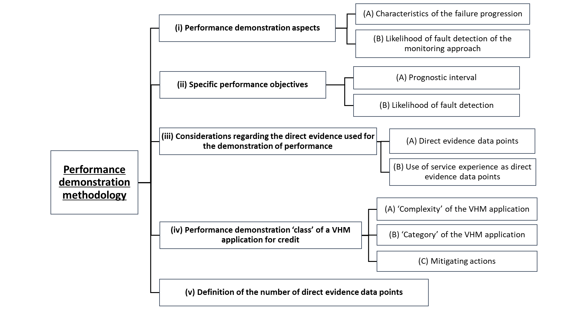
Direct evidence should be defined, developed and analysed to evaluate the fault detection performance aspects described in (i) below. The set of direct evidence data points provided should substantiate that adequate performance objectives are met (references are specified in (ii)). In addition, (iii), (iv) and (v) provide guidance on the kind of and how to determine the number of the direct evidence data points for a specific application. Figure 5 below summarises the structure of the guidance provided regarding the performance demonstration methodology for applications for credit.
Figure 5: Structure of the AMC sections addressing the performance demonstration methodology for VHM applications for credit
(i)Performance demonstration aspects
(A)Characteristics of the failure progression
The applicant should demonstrate that the failures to be prevented by a VHM application for credit have acceptable characteristics for the intended credit application.
Sufficient time should be demonstrated between the point at which the damage or degradation associated with potential incipient failures becomes clearly detectable by VHM and the ultimate failure consequences (i.e. prognostic interval (PI)). For this purpose, the applicant may investigate the failure progression up to its ultimate consequences or simply demonstrate that within a specified period of operation the detected incipient failure will not progress to ultimate consequences. This demonstration should consider how the failure may progress, evaluate the variability and scatter it may be subject to, and quantify their impact.
For this demonstration the applicant may already have well defined and established processes (e.g. for applications addressing the fatigue tolerance evaluation in compliance with CS 29.571/573). In such cases the applicant may propose to follow these. Alternatively, in case no established process is available, the following should be considered:
(a)Conservative test conditions should be defined based on the available understanding of the failure progression.
(b)Possible impacts of the progressing damage or degradation on surrounding elements should be considered.
(c)Additional tests should be considered to assess parameters affecting the variability of the failure progression. These may include any operating-, assembly-, manufacturing-, or environmental-related aspect that may impact the rate and way in which the failure progresses. Other aspects may include the characteristics (e.g. type, size, shape, orientation, etc.) of the damage or degradation.
(d)When it is not practical or technically feasible to evaluate all parameters that may impact the failure progression and/or when significant scatter is established, additional measures of conservatism may be needed. These measures may include additional conservatism applied to testing conditions and/or safety factors applied on conclusions from test results and service data.
(e)In cases where the failure progression is evaluated up to ultimate failure consequences, it should be established whether the failure progression reaches a condition from which further damage or degradation may no longer be reliably understood or conservatively evaluated, or from which the probability of detection reduces. In such cases, this point should be considered as the condition in which ultimate failure is reached.
(B)Likelihood of fault detection of the proposed monitoring approach
The likelihood of fault detection should be understood as a qualitative evaluation of the probability of the proposed monitoring approach to indicate the presence of damage or degradation at a specific point in the failure progression. In order to perform this evaluation and establish its adequacy for the intended VHM application, the applicant should pursue the following objectives:
(a)It should be demonstrated that the acquired and processed signal(s) produce consistent and reliable indicators that enable detection of the degraded condition. This should be achieved through the physical understanding of the mechanical response of the failure progression on the components being monitored and the characteristics of the VHM system. This detectable mechanical response should be demonstrated to occur systematically at some point within the failure progression and provide adequate likelihood of fault detection for the demonstrated PI.
(b)An adequate likelihood of fault detection should be ensured even for the worst foreseeable scenario from a detection point of view. This worst foreseeable scenario should be considered as a hypothetical failure progression with characteristics that result in the lowest likelihood of detection by the proposed monitoring approach. To establish this worst foreseeable scenario, the applicant should:
(1)consider the possible scenarios of failure progression, including the range of characteristics of the associated degraded conditions that may be present, how they may evolve and how they may affect the likelihood of detection;
(2)determine the maximum expected variability and scatter of the mechanical responses on the computed indicator values.
(c)For objectives (a) and (b) listed directly above, the following apply:
(1)Direct evidence data should be justified to simulate degraded conditions covering an adequate range of the possible mechanical responses generated by the failure progression.
(2)Sources of variability affecting the monitored signal(s) such as rotorcraft-to-rotorcraft, assembly, maintenance, and operating conditions should be considered. The applicant may justify that these do not significantly affect the likelihood of detection of the incipient failure. Alternatively, any sources of variability that may have a significant impact should be adequately characterised, which may require additional testing.
(3)The applicant should also consider the impact from scatter and noise signals that may be present on the rotorcraft.
(4)Only limited data from tests and/or in-service events is typically available or developed for the evaluation of the fault detection performance. Therefore, the applicant should consider service data from similar VHM applications, additional testing and/or safety factors to establish a conservative measure of the variability and scatter at the different stages of the failure progression.
(ii)Specific performance objectives
Note: The reference values provided in (A) and (B) below are approximate standards to be generally considered for VHM systems featuring credit applications. However, the applicant should consider that these may not be adequate for every application. For example, the applicant may need to fulfil more demanding objectives in cases where these reference values are not enough to meet the safety objective of a particular application. In addition, the applicant may also propose less demanding objectives in cases where, for example, mitigating actions are used in parallel to the VHM application for credit.
(A)Prognostic interval
The shortest PI expected to be experienced should be evaluated in accordance with (i)(A) above.
This PI should be demonstrated to ensure a minimum of three opportunities of detection when compared with the MIDR.
PI ≥ 3 * MIDR
(B)Likelihood of fault detection
The likelihood of fault detection should be evaluated in accordance with (i)(B) above.
The applicant should demonstrate that, from the point the degraded condition is considered clearly detectable in any failure progression scenario, there will be very high chances of triggering an alert at each opportunity at which the condition indicators are assessed against the alerting criteria. An example of such demonstration is provided in GM1 29.1465(e).
(iii)Considerations regarding the direct evidence used for the demonstration of performance
(A)Direct evidence data points
The applicant should define adequate and sufficient direct evidence to complete the demonstration of performance for the aspects described in (i)(A) and (i)(B) above. Each individual element of direct evidence (i.e. test, in-service event, etc.) should be considered as a single data point.
The number of direct evidence data points needed for the demonstration of performance would typically depend on characteristics of the application such as the variability and/or the scatter exhibited by the failure progression and the likelihood of detection. The sufficiency of the direct evidence data points used may only be confirmed at the end of demonstration of performance. At this point, it should be verified that the performance demonstration aspects have been adequately addressed (see (i)(A) and (B)) and the performance objectives are met.
Nevertheless, it would typically be relevant for the applicant to be able to estimate the number of direct evidence data points at the beginning of the design and development of a VHM application for credit. In order to establish and justify the number of direct evidence data points initially planned for each performance demonstration aspect, the applicant may choose to:
—rely on established methods,
—follow the process described in Figure 6 below, or
—propose an alternative approach.
Established methods are expected to already be in place to assess the failure progression characteristics for at least certain kinds of failure mechanisms (e.g. fatigue cracking failures addressed by CS 29.571/573). In addition, when a VHM application for credit is introduced to replace other means of monitoring or continuing airworthiness task(s), the applicant may already possess data characterising the failure progression. In these cases, the applicant should evaluate whether the available data is adequate and sufficient to complete the demonstration without further testing.
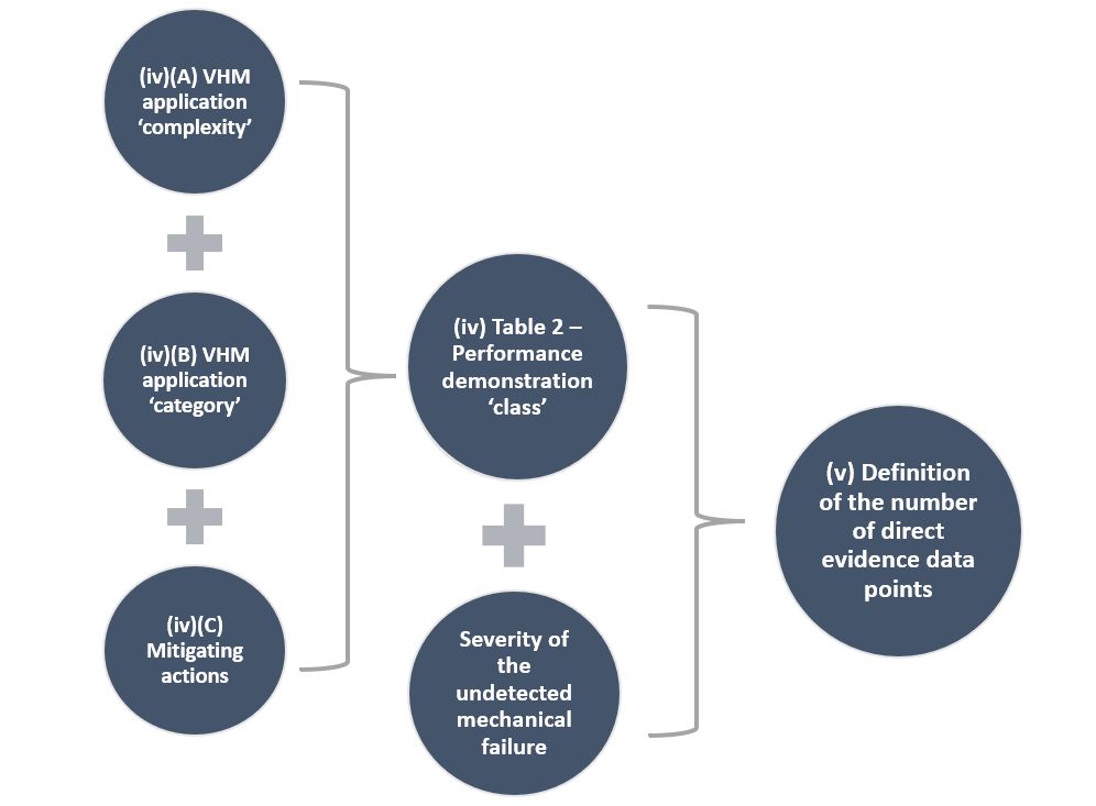
In the absence of established methods, Figure 6 below, summarises the process described in (iv) to identify the ‘class’ of an application for credit and, based on this, the number of direct evidence data points, as specified in (v).
The applicant may choose to follow this process to determine the number of direct evidence data points which are considered to provide a reasonable level of understanding. This level of understanding should be sufficient to determine whether the performance demonstration aspects are sufficiently understood or, instead, additional evaluations are needed. In case this process is used, the applicant should consider GM1 29.1465(f) when evaluating whether the process is well suited to the specific characteristics of the VHM application for credit.
As a third option, the applicant may also propose a new alternative approach. The process described in Figure 6 below is considered generally suitable. Nevertheless, other approaches may also be adequate or even needed (see GM1 29.1465(f) for more details).
Figure 6: Proposed process for establishing a reference number of direct evidence data points for the evaluation of (i)(A) or (i)(B) performance demonstration aspects of a VHM application for credit
(B)Use of service experience as direct evidence data points
From the direct evidence means listed in (f)(2)(ii)(A) of this AMC, the applicant should generally consider each data point to correspond to one dedicated test (including bench tests and rotorcraft trials).
Tests should be considered unless service experience (data from in-service events detected by means of VHM monitoring) can be justified to be relevant for the VHM application and to provide comparable levels of information relative to a test optimised for this purpose. For example, testing makes possible the clear correlation of the kind and level of damage or degradation with the resulting vibration signals and indicator values, as well as the characterisation of the operating time to failure. In cases where this information can be adequately extracted from the available data or its absence is adequately mitigated by other tests, one test result may be considered replaced by the data from such in-service event.
(iv)Performance demonstration ‘class’ of a VHM application for credit
This section supports (v) below in providing an acceptable approach to establish the number of direct evidence data points to be used in the performance demonstration of a VHM application. This approach is conceived with a focus on the evaluation of the likelihood of detection considering that this aspect requires further guidance but is also considered adequate for establishing the number of data points for evaluating the characteristics of the failure progression, if needed (see note immediately after Table 2 in (v) below). In principle, this number should be established independently for the evaluation of the failure progressions characteristics and the likelihood of detection.
When determining the direct evidence data points required for each performance demonstration aspect (i.e. (i)(A) and (i)(B) above), the applicant should establish the performance demonstration ‘class’. The performance demonstration ‘class’ reflects the potential impact on safety as well as the likelihood of an incorrect assumption as part of the compliance demonstration for CS 29.1465. It takes into consideration the complexity of the application, the safety margins and any mitigating actions. ‘Class 1’ reflects the highest potential impact on safety, while higher ‘class’ numbers are used as this potential impact reduces.
To determine the performance demonstration ‘class’ of a VHM application for credit, the following points should be taken into consideration:
(A)The ‘complexity’ of the VHM application, which effectively represents the difficulty to adequately characterise the performance demonstration aspects considering the variability and scatter they are subject to, as well as the number of parameters that have an influence.
(a)‘Complexity’ from a failure progression characteristics point of view
The applicant should evaluate the repeatability and capability to reach a good understanding of the failure progression characteristics. In order to support this demonstration for ‘non-complex’ VHM applications, it should be demonstrated that the variability can be understood and that the scatter is limited. For this purpose, the applicant should consider the following:
(1)Test results at similar conservative operating conditions and comparable parameters should be assessed.
(2)The maximum scatter (i.e. obtained from comparable data) for a ‘non-complex’ system should be limited to a factor of 10 between the maximum and the minimum operating times to failure.
(3)When a limited scatter of the rate of failure progression cannot be demonstrated or the variability and/or scatter evaluation are not performed in sufficient detail, the VHM application should be considered as ‘complex’ regarding its failure progression characteristics.
(b)‘Complexity’ from a likelihood of detection point of view
In order to justify a VHM application for credit as ‘non-complex’, it should be clearly established that the indicator(s) for the degraded and healthy conditions result in clearly differentiated distributions. For this purpose, the applicant should:
(1)identify and quantify any significant source of variability impacting the likelihood of fault detection;
(2)consider that the application should be considered as ‘complex’ when:
—a high number of sources of variability are identified;
—some sources whose impact may be significant are not evaluated; and/or
—substantial scatter in the likelihood of detection is observed;
(3)consider that a ‘non-complex’ VHM application typically features:
—simple and industry proven system architecture and sensors;
—standard and industry proven processing techniques;
—vibration signals that are directly attainable with limited noise or interfering signals;
—vibrations signals that are understood to be a consequence of the damage or degradation and which can be translated into condition indicators; and
—a clear increase of the likelihood of detection as the failure progresses.
(B)The ‘category’ of the VHM application defines whether ‘standard’ or ‘enhanced’ performance objectives are achieved. An application of ‘standard category’ corresponds to one that meets the minimum performance objectives for an application for credit defined above in (ii). Alternatively, the applicant may choose to demonstrate higher performance objectives (i.e. for an ‘enhanced’ VHM application). The applicant should consider the following objectives as the minimum standard for a VHM application of ‘enhanced category’:
(1)Failure progression characteristics
An ‘enhanced’ VHM application should support the determination of a PI of no less than 6 times the MIDR.
PI ≥ 6 * MIDR
(2)Likelihood of fault detection
The performance of an ‘enhanced’ application should be justified, based on the available data, to ensure that, at each opportunity at which the condition indicators are assessed against the alerting criteria following the degraded condition becoming clearly detectable, a missed detection of a damaged or degraded component is extremely unlikely.
In addition, the applicant may choose to demonstrate objectives higher than those for ‘enhanced’ applications in order to justify a greater reduction in the number of direct evidence data points.
(C)Mitigating actions used in support of or in parallel to the VHM application, if any. The applicant should consider whether any mitigating actions defined as part of the monitoring approach would be sufficient, on their own, to detect an incipient failure, given their associated detection capability and periodicity in accordance with (d)(3)(i). When this is the case, the VHM application in question may be considered of a reduced ‘class’ (i.e. ‘Class 1’ would become ‘Class 2’).
Based on these criteria, the performance demonstration ‘class’ of a VHM application can be identified as follows:
Table 1: Determination of the performance demonstration ‘class’ for VHM applications for credit
VHM application ‘category’ | Performance demonstration ‘class’ according to VHM application ‘category’ and ‘complexity’ | |
Complex | Non-complex | |
Standard | Class 1 | Class 2 |
Enhanced | Class 2 | Class 3 |
This assessment may result in a different performance demonstration ‘class’ being identified for each of the aspects considered (i.e. failure mode characteristics and likelihood of detection) and, therefore, different expectations regarding the number of direct evidence data points for each.
(v)Definition of the number of direct evidence data points
The number of direct evidence data points should be established independently for the evaluation of the failure progression characteristics and the likelihood of detection.
In accordance with the considerations from (iii) above, each direct evidence data point should correspond to an independent test, unless it can be justified otherwise. Following the identification of the performance validation ‘class’ as described in (iv) above, the applicant may propose a number of direct evidence data points in accordance with Table 2 below. Additional considerations regarding the numbers specified in Table 2 and when they may need to be adjusted are listed in GM1 29.1465(f).
Table 2: Number of direct evidence points for the evaluation of each performance demonstration aspect for VHM applications for credit according to their ‘class’ classification
Failure severity of monitored component(s) | Number of direct evidence data points according to VHM application ‘class’ | ||
Class 1 | Class 2 | Class 3 | |
Catastrophic | 7 | 5 | 4 |
Hazardous | 5 | 4 | 3 |
Major | 4 | 3 | 2 |
Note: The nature of the evaluation and the feasibility to ensure conservative results for certain kinds of failure may support alternative numbers of direct evidence data points relative to those provided in Table 2 above for the evaluation of the characteristics of the failure progression. Thus, when the applicant chooses to follow this process to establish the number of direct evidence data points to be used for this performance demonstration aspect, reduced numbers may be proposed provided that they are adequately justified. This should be based on the use of relevant testing conditions and safety factors, which should be proven by experience to render conservative results for the kind of failure being evaluated.
(3)Purpose of the controlled service introduction (CSI)
When defining the CSI plan for VHM applications for credit, the applicant should typically take into consideration the following:
(i)The performance demonstration methodology should identify the assumptions involved in the demonstration of performance requiring confirmation by means of evaluation of in-service data.
(ii)The in-service data necessary for confirmation of these assumptions should be specified accordingly and used in the preparation of the CSI plan (see paragraph (k) of this AMC for further details).
(iii)Unless otherwise agreed at the time of the approval, implementation of an approved VHM application for credit will not be subject to completion of the CSI. Thus, sufficient confidence in these assumptions should be provided for the certification of the VHM application for credit.
(iv)In case the applicant chooses to rely on information from the CSI phase to complete or complement the demonstration of performance for an application for credit, the following should be considered:
(A)This option may be of interest, for example, in cases where certain parameters affecting the characteristics of the failure progression and/or the likelihood of detection require significant testing on the rotorcraft. Thus, the understanding of their impact would be limited at certification, pending data from the CSI.
(B)It should be clearly established at the time of approval whether no credit or only partial credit is granted.
(C)In case partial credit is granted, this should be supported by means of appropriate safety factors in the demonstration of performance.
(D)The CSI plan may be used to record the preliminarily agreed activities to achieve granting of the full credit.
(E)Typically, implementation of the full credit will require a separate approval following gathering and evaluation of the in-service data.
(h)VHM applications in support of compliance with an operational regulation
This paragraph provides specific Acceptable Means of Compliance for VHM systems that are relied upon to support compliance with an operational regulation. These are expected to provide a minimum level of additional safety by increasing the likelihood of early detection of incipient failures. Nevertheless, applicants developing VHM systems on a ‘no hazard/no credit basis’ are advised to follow the content of this AMC, including subparagraph (2) of this section as guidance for establishing adequate system performance.
(1)Monitoring scope
In order to substantiate that the VHM system provides the aforementioned additional safety, the applicant should demonstrate that the scope of components being monitored is in line with that defined in the operational regulation that the system is intended to support compliance with.
For point SPA.HOFO.155 of Regulation (EU) No 965/2012, the scope is defined as ‘critical rotor and rotor drive systems’ and further clarified in associated AMC as ‘rotating critical components’. This should be understood as parts of the rotors and rotor drive systems, the failure of which could prevent continued safe flight or safe landing, or whose failure could have catastrophic and/or hazardous consequences.
As specified in CS 29.1465(b)(3), VHM may not be required for some of these parts, provided that alternative means of monitoring are provided. For many failure modes, there may be other compensating provisions which can provide protection against the risk of premature failure. Nevertheless, the purpose of operational regulations that mandate the fitment of VHM systems is typically an additional safety benefit by means of an increased likelihood of early detection of incipient failures. However, it will not be necessary to implement VHM for a given failure mode if no safety benefit may be established. For establishing the safety benefit of implementing VHM, the applicant should consider the capability that the system may achieve after introduction into service through the gathering of data from the fleet and the development of improved indicators and alerting criteria.
In addition, CS 29.1465(b)(3) also states that other means of health monitoring need to be substantiated when VHM monitoring is not provided for components within the scope of the operational regulation requirements. Such other means of health monitoring may be any alternative system (e.g. chip detection, temperature monitoring, etc.) or continuing airworthiness tasks which are demonstrated to adequately identify the presence of damage or degradation on these components.
(2)Demonstration of performance
Adequate performance should be demonstrated in accordance with paragraph (f) of this AMC. Additional considerations are listed below taking into account that the demonstration of performance is to be commensurate with the role of the VHM system from an airworthiness perspective:
(i)The applicant should define the necessary indicators and alerting criteria to ensure that all components specified in the scope defined in (1) above are adequately monitored taking into account the failures to be prevented as identified in the safety analysis required by CS 29.1465(b)(1). When doing this, the applicant may experience difficulties to ensure that the defined criteria are effective to prevent premature failure while maintaining acceptable false alarm rates without applicable and representative direct evidence. This may be the case of, for example, rotor or rotor drive system components whose condition indicators are too low or too scattered, preventing the definition of appropriate learnt thresholds, and for which representative computed indicators from healthy and eventually also degraded components are required to define effective and reliable fixed thresholds or threshold learning algorithms.
Therefore, in support of the definition of alerting criteria for VHM applications for compliance with an operational regulation, the applicant should consider the following:
(A)For those components for which experience has shown that thresholds defined in the absence of applicable test or in-service data of a component subject to damage or degradation are not reliable and/or effective, the applicant may propose to approve the system without defined alerting criteria for those components (see (3) below for further guidance on establishing alerting criteria during the CSI).
(B)Data gathered from service should be statistically analysed to ensure that the alerting criteria are adequately set to indicate the presence of damage or degradation. This may require the evaluation of components replaced or repaired due to a VHM alert to verify that their condition was in line with the VHM indication.
(C)VHM data from components identified through other means as damaged or degraded and whose condition should have been indicated by the VHM system should be investigated. If deemed necessary, the alerting criteria should be amended.
(ii)It is not expected that direct evidence is developed to support the performance demonstration for this kind of VHM system applications.
(iii)Nevertheless, it should be demonstrated that the VHM system design and the implemented monitoring approach are expected to provide an adequate fault detection performance at the time of the approval. This should be achieved by justifying that the monitoring approach relied upon for each monitored component provides reasonable chances of early detection against the risk of premature failure. For this purpose, indirect evidence means from those listed in (f)(2)(ii)(B), as well as service experience from existing systems, where available, should be used to:
(A)justify the adequacy of the mechanical response(s) targeted as a reliable indication of damage or degradation associated with incipient failures for each monitored component;
(B)detail why the sensor location, signal(s) acquired and subsequent processing are considered appropriate for early detection;
(C)justify that the initial alerting criteria and the processes used to adjust them in service provide adequate detection capability, while ensuring acceptable false alarm rates. This justification should consider the VHM system design characteristics and the proposed ICA to be followed in the event of an indication from the system;
(D)include in the design assessment required by CS 29.1465(b)(1) consideration of the characteristics of the failure progression for each part to support the existence of an adequate PI prior to ultimate failure. These characteristics should be derived from the applicant’s experience and industry know-how. This consideration should be taken into account at the time of defining the recommended and maximum intervals of VHM data acquisition and review defined in accordance with points (e)(1) and (2) of this AMC. It should be ensured that these intervals maximise the possibilities of early detection wherever it is deemed feasible and practical.
Note: When showing compliance with CS 29.1465(b)(2), the applicant may choose to use Table 1 of GM1 29.1465 for reference. However, it is not always necessary for the VHM system to cover the complete capability defined in this table. If alternative methods are proposed, which can be shown to be effective and reliable and which are to the satisfaction of the Agency, then these can also be accepted.
(3)Purpose of the controlled service introduction (CSI)
As a result of the limited or no supporting direct evidence for these VHM applications, the performance demonstration should be subject to validation in service through the completion of a CSI, as detailed in paragraph (k) of this AMC. When defining the CSI plan for VHM applications for compliance with an operational regulation, the applicant should typically take into consideration the following:
(i)The demonstration of performance would rely significantly on assumptions, which may include the read-across of data from similar applications or the use of engineering judgement. Therefore, the applicant should carefully identify the characteristics of VHM system and/or aspects of its implementation that require evaluation in service and plan the CSI accordingly.
(ii)The applicant should also ensure that appropriate data is gathered during the CSI to confirm, set and/or adjust alerting criteria as required. When no initial alerting criteria are defined for certain components at the time of approval because of insufficient data, the applicant should ensure that the necessary data to define the missing alerting criteria is gathered within the minimum interval possible.
(iii)A VHM system approved in support of compliance with an operational regulation should be clearly recorded as such in the TCDS, and its implementation for this purpose should not be dependent upon completion of the CSI.
(i)Ground-based system
(1)General considerations
The ground-based system may include COTS hardware and software as part of the platform on which the application software is running. Qualification of such hardware and software might not be practicable given the range of set-ups and configurations available. However, for VHM system applications for which qualitative safety objectives higher than DAL C have been identified in accordance with paragraph (d) of this AMC, the use of non-qualified hardware and software platforms should be limited in order to ensure the end-to-end system integrity and safety. Therefore, for such applications, non-qualified platforms should not be solely relied upon for the processing of VHM data and/or determining the need to provide indications regarding the condition of the components monitored. Alternatively, for VHM systems with non-qualified platforms that are solely relied upon for VHM applications for which qualitative safety objectives higher than DAL C have been identified in accordance with paragraph (d) of this AMC, adequate independent verification means should be implemented to ensure the end-to-end system integrity and safety.
Any ground-based system architecture requirements should be specified as part of the ICA for the VHM system, including man-machine interfaces.
(2)Ground-based software
The reliability of ground-based software should not compromise end-to-end system integrity and safety.
Ground-based systems can consist of a COTS platform, without software or hardware qualification, whose technological and performance features as available on the market may change very rapidly. Therefore, the specifications of the host platform configuration characteristics and their authorised range for which the applicant guarantees the VHM performance and integrity should be provided through the ICA. Alternatively, the necessary set of test procedures allowing for operators to check VHM ground-based software compatibility with their host platforms should be provided through the ICA, in case configuration characteristics cannot be easily identified.
As the ground-based application software of the VHM system is intended to be installed on a COTS platform, the lack of development assurance for the platform should be compensated for by:
(i)development assurance at application software level; and
(ii)verification at VHM end-user level (operator).
The applicant should define and implement a software development assurance process for the ground-based application software of the VHM system. It should include in particular extensive verification/testing21 of the ground-based VHM functionality, including robustness test cases, in a repeatable and standardised manner, including the worst-case authorised platform configurations when identified. This could be achieved by means of development assurance processes (e.g. RTCA DO 178()/EUROCAE ED 12(), RTCA DO-330/EUROCAE ED-215, RTCA DO-278()/EUROCAE ED-109(), etc.) or other appropriate means to be proposed by the applicant.
As part of the ICA, an installation procedure of the ground-based software should be developed by the applicant to be provided to end users, to verify the correct behaviour of the software on the end-user ground-based platform configuration(s). It is intended to be also used to ensure the compatibility and the correct behaviour in case new platforms (e.g. new OS, new processors, etc.) or new application software versions are released.
The end-to-end system integrity of the VHM information (including possible conversion means) should be ensured, e.g. by means of cyclic redundancy checks (CRC) protection of the data files or any other adequate means.
(j)Technical publications
Appropriate ICA are required by CS 29.1529 and Appendix A, which includes the VHM system itself and its applications. Thus, ICA and any other necessary supporting documentation should be available at entry into service and updated whenever necessary during the service life of the system.
(1)The ICA should typically include the following:
(i)Instructions to support the processing of each of the VHM system’s indications in accordance with (e)(4).
(ii)The recommended and MIDR in accordance with (e)(3).
(iii)The necessary procedures to ensure that sufficient complete data sets are available to allow for full diagnostics evaluation at the MIDR. In addition, the following details should be specified:
(A)The recommended and the minimum frequency of VHM data acquisition in accordance with (e)(1), as well as the necessary procedures to ensure that at least one complete data set is recorded within the required frequency.
(B)Means and procedures for data transfer, processing, networking and data integrity assurance.
(C)Methods to ensure the reliability of this process.
(D)The expected time required for upload/download and retrieval of data/health report.
(E)Facilities for storage of all data downloaded from the VHM systems and which permit timely access to the data.
(iv)The procedures to ensure that any alert is acted upon at an interval no greater than the MIDR.
(v)Provisions to support the mitigation of potential misleading information, missing or failed acquisition, and conflicting data from redundant sensors.
(vi)Effective scheduled maintenance to be carried out on the VHM system itself, when applicable, including inspections to confirm sensor performance and system functionality.
(vii)Troubleshooting and maintenance instructions to restore the VHM system functionality from any system failure.
(viii)Supporting information for all maintenance required on the VHM system, including illustrated parts catalogue/illustrated parts breakdown and wiring diagrams.
(ix)Instructions to calibrate the system and verify that the computed indicators are representative of the condition of the monitored components.
(x)A maximum period of unavailability for each of the VHM system functionalities for inclusion, when required, in maintenance instructions, taking into consideration MMEL instructions. These periods should be defined in a way that ensures that the MIDR of the different VHM applications are supported.
(xi)In addition, for VHM applications for credit, the applicant should consider the need for the following additional details:
(A)Alternate means for monitoring in case of VHM system malfunction or unavailability.
(B)Procedures to verify the continuous capability of the VHM system to evaluate the condition of the parts subject to credit.
(C)Procedures to support the transfer of parts between rotorcraft.
(2)Other supporting documentation may include:
(i)operating instructions detailing the operation of the VHM system, including any ground-based elements or functions; and
(ii)the required flight manual instructions when direct interface exists between the flight crew and the VHM system.
(k)Controlled service introduction
A CSI is a set of post-approval activities that are generally needed to ensure that the objectives of the VHM system applications are adequately fulfilled in service. Unless the applicant can justify otherwise, a CSI should be planned at the certification phase and implemented in service.
The objectives of the CSI should be defined to address those aspects of the VHM system and associated monitoring approach whose demonstration of compliance is supported by assumptions.
These assumptions may have been considered in the demonstration of the fault detection performance, involving, for example, the representativeness of the testing conditions relative to the rotorcraft or the evaluation of variability and scatter in cases of limited data gathered. Other assumptions may involve other aspects that ensure that the monitoring approach defined is effective, which may include aspects such as the actual operation the rotorcraft is subject to, or the ground segment set-up for the VHM system used by operators.
The applicant should consider that completing the compliance demonstration without relying on any assumption and/or ensuring that every assumption is fully confirmed prior to introduction into service is generally challenging and typically requires a significant amount of VHM data gathered not only from tests but also in flight.
For VHM applications for credit and in support of compliance with an operational regulation:
(1)The applicant should establish a CSI plan detailing the VHM system applications concerned and specify for each of them:
(i)the objectives to be considered and associated KPIs and targets, as applicable;
(ii)the data requirements from the fleet in support of the CSI activities listed (further details are provided in point (8) below); and
(iii)the criteria for closure of the CSI, in line with point (4) below.
(2)The list below specifies a generic list of CSI objectives that typically need to be considered. The applicant should evaluate the needs of the VHM application in question and determine which of these need to be addressed and which criteria should be met for each objective.
(i)Acquisition: the VHM system acquisition cycle enables data acquisition at an adequate frequency for all types of operations.
(ii)Data availability: sufficient data is available at each VHM data review interval to evaluate the condition of monitored components according to every indicator and to perform any additional analysis needed for fault isolation.
(iii)Data review: the VHM data review interval observed is in line with that defined in the ICA and downloads, when applicable, are successful and free from errors.
(iv)Fault detection performance: in case of damage or degradation associated with incipient failures on the monitored components, the VHM system can provide early indication.
(v)VHM system hardware reliability: the VHM system hardware and installation are reliable (including airborne and ground-based systems, as applicable).
(vi)Ground-based system software reliability: required for ground-based systems using COTS software platforms.
(vii)Maintenance and troubleshooting burden: the processing of alerts and any subsequent tasks do not generate an increased risk of errors.
(viii)VHM usability and maintainability: the VHM system is usable (including pilot interface, if any, and ground segment man-machine interface) and maintainable (procedures for calibration, software update, troubleshooting, etc.).
(ix)Effectiveness and completeness of the ICA: the ICA address all indications provided by the VHM system, and the instructions are effective for their analysis and any required subsequent fault isolation.
(3)Examples of KPIs and recommended targets for each of the objectives listed in (2) above are provided in GM1 29.1465(g).
(4)The CSI plan should be presented to and accepted by the Agency as part of the compliance demonstration of the VHM system with CS 29.1465.
(5)The CSI should only be closed once its objectives have been fulfilled. For this purpose, the applicant should document how this is demonstrated, considering the evaluations of KPIs, the data gathered versus the targets selected, and feedback from the operators involved in the CSI plan. In addition, any other relevant event or finding should be duly recorded and investigated. Finally, the CSI closure process should be duly documented and:
(i)provided to the Agency for any of the CSI activities necessary in support of the demonstration of compliance of a VHM credit application. The Agency should concur with the fulfilment of the CSI objectives and, thus, the confirmation of the assumptions addressed by the CSI; or
(ii)agreed with the operator(s) involved, for any other CSI activities. The Agency should be informed and consulted in case of disagreement between the applicant and the operator(s).
(6)The CSI activities should typically be performed in close collaboration with a number of operators. In addition, operator feedback should be used in the evaluation of some CSI objectives. Therefore, the applicant should consult the operators involved for the definition and evaluation of the progress of the CSI activities.
CSI activities may also be used to validate objectives which are not directly related with demonstration of compliance with CS 29.1465. These may include ancillary elements to VHM operation such as those described in GM1 29.1465 (h) and (j).
(7)In case of any findings questioning the assumptions addressed by the CSI, the applicant should perform a detailed evaluation of the potential impact, confirm whether the objectives of the VHM system applications are fulfilled and, when needed, report to their competent authority for continued airworthiness. In addition, the applicant should report to the Agency at regular intervals the status of and progress on the activities planned in the CSI plan.
(8)In order to provide meaningful conclusions, the applicant should identify the requirements regarding in-service experience to be acquired to ensure that the VHM data gathered as part of the CSI is complete and comprehensive. These requirements should include the number of rotorcraft, the number of operators, the calendar time and the accumulated flight hours. Within the definition of these requirements, the applicant should consider the need to gather data representing the complete scope of usage the rotorcraft is subject to. This may include consideration of type of operations, environmental conditions and ageing effects.
The recommended minimum in-service experience included in Table 3 should be considered in support of the approval of a new VHM application.
Table 3: Recommended minimum in-service experience for CSI completion
Parameter | Recommended minimum data set |
Number of rotorcraft | ≥ 8 |
Number of operators | ≥ 2 |
Calendar time | ≥ 2 years |
Flight hours | ≥ 5 000 |
The applicant should consider the characteristics of the VHM system and the needs of the CSI to adjust these requirements, when needed. Changes to these requirements may also be proposed to optimise the CSI, provided that the completeness of the results and the validity of the conclusions are not adversely affected.
(9)In addition, to evaluate the progress of the CSI activities over time, the plan should define a minimum accumulated operating time and/or calendar time for KPI calculation and review. Generally, an initial assessment may be performed taking into account the initial 1 000 flight hours, and then the status may be checked again every 1 000 flight hours. Once the operating fleet is sufficiently wide, the KPIs might be computed yearly, considering the last 1 000 flight hours.
(l)Pilot interface and cockpit indications
Although VHM systems do not strictly require a cockpit interface for pilot interaction or for providing VHM alerts, such a feature may be introduced. This section addresses this functionality focusing on cockpit indications generated by the VHM system.
Pilot interaction with the VHM system, if any, should be specified and should not adversely impact the crew’s workload. Where applicable, the applicant should perform a crew workload assessment and a human factors evaluation in accordance with CS 29.1302 and the other appropriate certification specifications.
The applicant may consider in-flight or on-ground VHM cockpit indications for certain VHM applications. For this purpose, the definitions included in GM1 29.1465(a) for the different kinds of cockpit indications should be considered. When applicable, the applicant should address them as follows:
(1)Real-time VHM alerting
Due to the characteristics of VHM systems and the nature of the mechanical responses they monitor, it is very difficult to design and demonstrate that a VHM system has sufficient capability and reliability to provide cockpit indications in flight requiring immediate pilot actions which may result in hazardous or catastrophic consequences for the rotorcraft. Such actions typically involve the requirement to land immediately or within a limited period of time. It is considered that any failure monitored by VHM that would require such immediate and drastic pilot action should be prevented through robust design methodologies of the monitored mechanical system, ensuring that the probability of occurrence is in line with the safety objective.
Nevertheless, real-time VHM alerting could be implemented where the cockpit indication will instruct the pilot to perform less severe actions such as reducing power, monitoring other instruments, or landing as soon as practicable. Considering the potential impact of real-time VHM alerting on crew workload, the following are considered as key elements to achieve a system fit for this purpose:
(i)It should be justified that the probability of occurrence of any preceding degraded condition that, if undetected, may ultimately lead to the failure is commensurate with the associated severity of the RFM procedure for the corresponding indication.
(ii)The demonstration of performance should be performed in accordance with paragraphs (f), (g) and/or (h), as applicable. Nevertheless, the applicant should consider dedicated testing activities to validate the monitoring performance and capability of detection, including seeded flaw tests and validation on the rotorcraft.
(iii)Means providing increased reliability of the system installation and monitoring should be implemented (sensor redundancy, improved mounting means, combination of condition indicators, etc.).
(iv)The false alert rate should be minimised and justified to be consistent with the quantitative objective associated with the severity identified in the FHA for the corresponding RFM procedure, taking into account the possible operational scenarios.
(v)When warning, caution or advisory lights are installed in the cockpit, the applicant should consider compliance with CS 29.1322.
(vi)The RFM should include the necessary instructions to allow interpretation and management of any information which may include alerts provided by the VHM system in flight.
(2)Near real-time VHM alerting
This approach can be considered for degradation modes for which the demonstrated time between detection and failure is limited, to support operators without the capabilities to perform regular downloads and reviews of VHM data, or to ensure that the VHM system does not solely rely on the ground-based system for the generation of alerts. It is considered that, when such kind of VHM application is needed due to the limited time demonstrated between detection and failure, additional mitigating actions should also be implemented and the key elements (i) to (v) listed in (1) above for real-time VHM alerting are also considered applicable.
In addition, regardless of the exact use of a VHM application relying on near real-time VHM alerting, it is recommended that the applicant considers implementing some of the key elements (i) to (v) listed in (1) above, due to the potential impact on the operability of the rotorcraft.
(3)Real-time VHM data transfer
It is considered that the intent of such applications should be oriented to improving the response time to any VHM indication and thus to improve rotorcraft availability. However, the applicant should consider implications on avionics certification and cybersecurity.
(m)Master minimum equipment list (MMEL) recommendation
The applicant should evaluate the impact on safety from temporarily inoperative VHM applications, and determine the need for including associated elements of the VHM system in the rotorcraft MMEL. This may generally be the case for VHM applications for credit. In such cases, the applicant should define an appropriate rectification interval, in accordance with CS-MMEL, and/or revert to maintenance and flight procedures applicable for the rotorcraft configuration without the VHM application for credit.
[Amdt 29/12]
GM1 29.1465 Vibration health monitoring
ED Decision 2024/009/R
(a)Definitions
(1)Acquisition cycle: the process and criteria defined within the VHM system determining when vibration signals are recorded, which ones are recorded and in which order, how long each recording takes, etc.
(2)Alarm: an alert that, following additional processing or investigation, has resulted in the identification of specific maintenance action being required to restore the monitored components to serviceable conditions. This maintenance action is to be accomplished within a defined interval in accordance with the associated instructions for the management of the alert.
(3)Alert: an indication produced by the VHM system in the event of any alerting criteria of the VHM application being fulfilled. Any alert is managed by specific instructions defined by the applicant, which may include further processing or investigation by the operator (i.e. organisation responsible for the rotorcraft continuing airworthiness management) to determine if maintenance action is required.
(4)Alerting criteria: criteria defined by the applicant that, when fulfilled based on the computed VHM indicator(s) involved, will lead to raising an alert.
(5)Application software: dedicated software that performs a specific function for the VHM system. This may include computation of condition indicators and/or determination of the need to produce an indication.
(6)Commercial off-the-shelf (COTS): commercially available equipment hardware and software sold by vendors through public catalogue listings that is not qualified against aeronautical development assurance standards.
(7)Condition: the status or health of a mechanical component or assembly. Evaluation of the condition should include consideration of any kind of damage or degradation that may have an impact on the integrity and/or functionality of the component or assembly.
(8)Credit: demonstrated capability of the VHM system to perform a relevant function(s) towards ensuring the airworthiness of the rotorcraft in accordance with AMC1 29.1465(a)(3)(iii).
(9)Damage: physical harm that may occur in mechanical components or assemblies, potentially impairing their integrity and/or functionality.
(10)Degradation: state of declining quality, functionality and/or integrity.
(11)Degraded condition: condition of a part or assembly subject to damage or degradation.
(12)End-to-end process: the complete process followed by a VHM system to achieve fault detection. It includes all the steps from signal acquisition to confirmation of the alert and correction of the affected part or assembly to serviceable conditions.
(13)False alarm: an alarm whose preceding alert has incorrectly indicated the need for maintenance action. This is typically determined following investigations of the findings associated with the consequent maintenance action.
(14)False alert: an alert that after further processing or investigation has been determined to not require any further action in accordance with the associated instructions for the management of the alert.
(15)Failure: a state in which the operation of a component, part or element is affected in a way such that it can no longer function as intended.
(16)Failure progression: the process by which the degraded condition of a part or assembly progresses, increasing the decline of its status or health. Ultimately, if undetected, it may lead to the complete failure of the part or assembly due to loss of integrity and/or functionality.
(17)Ground-based system (ground segment): items of the VHM system located off-board, on the ground or in a collaborative workspace such as web-based services, used by the operator (i.e. organisation responsible for the rotorcraft continuing airworthiness management) to:
—transfer VHM data from the airborne system;
—store, access, process, display and review this data; and
—perform additional VHM data analysis.
(18)Incipient failure: state of a part or assembly subject to damage or degradation which, if not timely rectified, will lead to failure of the part or assembly.
(19)Indication: any message, advisory or warning generated by the VHM system. Thus, this includes, but is not limited to, alerts and alarms.
(20)Key performance indicator (KPI): a measure applied to specific aspects of the VHM system operation to evaluate its adequacy in service.
(21)Maximum interval between VHM data reviews (MIDR): the maximum period between reviews of the data provided by the VHM system, as defined in the ICA.
(22)Mitigating actions: continuing airworthiness tasks or alternative means of monitoring used in combination with a VHM application, which are demonstrated to be capable of adequately monitoring the associated failure as a means to reduce the reliance on a VHM application for credit to ensure airworthiness.
(23)Monitoring approach: this encompasses the aspects associated with a VHM application that are defined as part of the VHM system design, installation and associated documentation in order to fulfil its intended objectives. This typically includes:
—the characteristics of the VHM system allowing reliable indicators, which are consistently representative of the condition of the monitored components, to be computed;
—the characteristics of the VHM that ensure that indicators are computed at an adequate frequency, timely available and adequately interpreted by personnel involved in the continuing airworthiness, including sensor locations and characteristics, acquired signals and processing, VHM indicators computed, etc;
—the alerting criteria of the system enabling indication to personnel involved in the continuing airworthiness of anomalous behaviour indicating that damage or degradation may be present on any monitored component with sufficient margin before any failure may occur;
—the procedures to be implemented in the continuing airworthiness in support of fulfilling the functions of a VHM system application; and
—mitigating actions.
(24)Near real-time VHM alerting: VHM applications that perform signal acquisition and indicator processing in flight, and that are used for a cockpit indication provided to the crew only before take-off or after landing.
(25)Operational regulation: any regulation addressing rotorcraft operations which may mandate fitment of VHM systems. Currently, this includes point SPA.HOFO.155 of Subpart K of Annex V (Part-SPA) to Regulation (EU) No 965/2012.
(26)Operator: an organisation responsible for the continuing airworthiness management of one or more rotorcraft of the type concerned.
(27)Preceding degraded condition: the condition/state of mechanical parts or assemblies featuring forms of damage and/or degradation that typically indicate the presence of incipient failure. These will typically lead to higher level of damage or degradation through the exposure to further operation and, ultimately, if undetected, to complete failure.
(28)Prognostic interval (PI): the demonstrated minimum safe operating time for a part or assembly subject to damage or degradation between the point at which this degraded condition can be detected and the rotorcraft becoming unairworthy. The point at which the rotorcraft becomes unairworthy may be when ultimate failure can occur, or simply the point up to which the applicant has demonstrated that safe operation is ensured.
(29)Real-time VHM alerting: VHM applications that perform signal acquisition and indicator processing in flight, and that are used for a cockpit indication requiring immediate or nearly immediate action by the flight crew.
(30)Real-time VHM data transfer: VHM system applications that rely on the transfer of data during flight to the ground. The transferred data may correspond to the indicator(s) processed on the rotorcraft or raw data for computation of the indicator(s) on the ground-based system.
(31)Scatter: the scatter experienced by performance demonstration aspects (i.e. in the vibration signal and/or condition indicator, or the rate and way in which the failure progresses) at conditions that are considered equivalent.
(32)Variability: the changes experienced by performance demonstration aspects (i.e. in the vibration signal and/or condition indicator, or the rate and way in which the failure progresses) resulting from changes in affecting parameters (e.g. operating conditions).
(33)Vibration health monitoring (VHM): use of data generated by processing vibration signals to detect potential incipient failures, generally exhibited as degradation of the mechanical integrity of dynamic components, typically within the rotors and/or rotor drive systems.
(34)VHM application (also application): a VHM function implemented for a defined purpose.
(35)VHM application for credit (also application for credit): a VHM function implemented for a defined purpose in support of ensuring the airworthiness of the rotorcraft, as detailed in AMC1 29.1465(a)(3)(iii).
(36)VHM indicator (indicator): a VHM indicator is the result of processing sampled data by applying an algorithm to achieve a single value, which relates to the condition of a component with respect to a particular failure mode.
(37)VHM system: a VHM system typically features airborne and ground segments which, depending on the design and intended functions of the system, typically include vibration sensors and the associated wiring, airborne electronic hardware for data acquisition, processing, and means for the storage, transfer and display of data. For the purpose of AMC1 29.1465, the associated instructions for operation of the system should also be considered as part of the VHM system.
(b)System design considerations
(1)Sensors: They are the pieces of hardware that measure vibration. They should provide a reliable signal with appropriate and defined performance. The position and installation of a vibration sensor is as critical as its performance. Sensor selection, positioning and installation should be designed to enable analysis of the processed signals to distinguish the vibration characteristics of the declared monitored component failure modes. Built-in test capability is necessary to determine the correct functioning of the sensor. Maintenance instructions should ensure that the correct function, and any calibration, of sensors and their installation are adequately controlled.
(2)Signal acquisition: It is likely that processed VHM data will be sensitive to the flight regime of the rotorcraft. For this reason, it is desirable to focus data acquisition on particular operating conditions or phases of flight. Consideration should be given to the likely operation of rotorcraft that may utilise the VHM system and the practicality of acquiring adequate data from each flight to permit the processing to be performed to the required standard. The method of vibration signal acquisition should be designed so that:
(i)the vibration signal sampling rate is sufficient for the required bandwidth and to avoid aliasing with an adequate dynamic range and sensitivity;
(ii)the data acquired from the vibration signal is automatically gathered in specifically defined regimes at an appropriate rate and quantity for the VHM signal processing to produce robust data for fault detection; and
(iii)if the mission profile does not allow for regular acquisition of complete data sets, then the data acquisition regimes are capable of reconfiguration appropriate to particular flight operations or provisions are included in the ICA to ensure an adequate frequency of data acquisition.
(3)Signal processing: A rotorcraft’s rotor and rotor drive systems are a mixture of complex and simple mechanical elements. Therefore, the signal processing or the analysis techniques utilised should reflect the complexity of the mechanical elements being monitored as well as the transmission path of the signal and should be demonstrated as being appropriate to the failure modes to be detected. The objective of processing the sampled data should be to produce VHM indicators that clearly relate to vibration characteristics of the monitored components, from which the health of these components can be determined. A key part of the success of in-service VHM is the signal-to-noise enhancement techniques such as vibration signal averaging for gears and signal band-pass filtering and enveloping for bearings. These techniques are used to generate enhanced component vibration signatures prior to the calculation of the VHM indicators. Accordingly, the method of signal enhancement should be shown to be effective. The method of signal processing and the analysis techniques utilised to generate the data used for fault detection should be defined for the claimed detection capability (see Table 1 below).
Recording and storage of some raw vibration data and the processed vibration signal, from which the indicators are derived, may also be of significant diagnostic value. Typical signal processing techniques include:
(i)asynchronous power spectrum where phase information or frequency tracking is not required;
(ii)synchronous spectrum where phase information or frequency tracking is required;
(iii)band-pass filtered signal envelope power spectrum analysis (a recommended technique for gearbox bearings);
(iv)synchronous averaging for time and frequency domain signal analysis (a recommended technique for gearbox gears); and
(v)band-pass filtering and the measurement of filtered signal statistics, including the crest factor (can be used for bearings not within engines or gearboxes).
Further signal enhancement techniques are typically required in the calculation of certain VHM indicators targeted at detecting specific condition features (e.g. localised signal distortion associated with a gear tooth crack).
Table 1: Typical VHM indicators & signal processing techniques
Assembly | Component type | Types of VHM indicators used |
Engine to main gearbox input drive shafts | Shafts | Fundamental shaft order and harmonics |
Gearboxes | Shafts | Fundamental shaft order and harmonics |
Gears | Gear meshing frequency and harmonics, modulation of meshing waveform, impulse detection and energy measurement, non-mesh-related energy content | |
Bearings | High-frequency energy content, impulse detection, signal envelope modulation patterns and energies correlated with bearing defect frequencies | |
Tail rotor drive shaft | Shafts | Fundamental shaft order and harmonics |
Hangar bearings | As for gearbox bearings, but can utilise: simple band-passed or signal energy measurements | |
Oil cooler | Oil cooler blower and drive shaft | Fundamental shaft order and harmonics, blade pass frequency |
Main and Tail rotor | Rotors | Fundamental shaft order and harmonics up to blade pass frequency, plus multiples of this |
(c)Use of AMC1 29.1465(d) for the identification of the VHM system safety objectives
The following examples are provided to ease interpretation of the approach described in AMC1 29.1465(d)(4).
(1)Example 1
(i)A VHM application for credit monitoring a hazardous failure with minimum mitigating actions (in accordance with AMC1 29.1465(d)(3)(i)(A)). As depicted below (see ① in Figures 1, 2 and 3 below) and in accordance with AMC1 29.1465(d)(4), such VHM application would correspond to:
—Case 2, and
—1E-05 per flight hour and DAL C as the quantitative and qualitative safety objectives, respectively.
(ii)If the mitigating actions for this same VHM application were extended (as per AMC1 29.1465(d)(3)(i)(B)) or a low probability of occurrence of any preceding degraded condition (as per AMC1 29.1465(d)(3)(ii)) was demonstrated in addition to the minimum mitigating actions, the application (see ❶ in Figures 1, 2 and 3 below) will correspond to:
—Case 3, and
—1E-04 per flight hour and DAL C as the quantitative and qualitative safety objectives, respectively.
Figure 1: Identification of cases for alleviation of VHM system safety objectives for Example 1
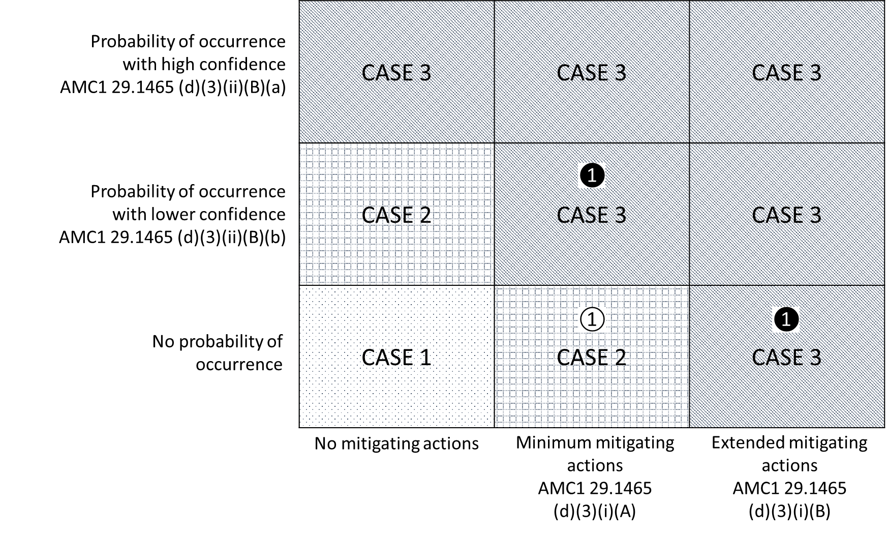
Figure 2: Quantitative safety objectives identified as a function of the severity of the undetected mechanical failure and the case from Example 1

Figure 3: Qualitative safety objectives identified as a function of the severity of the undetected mechanical failure and the case from Example 1

(2)Example 2
(i)A VHM application for credit monitoring a catastrophic failure with low probability of occurrence, which is demonstrated with lower confidence in accordance with AMC1 29.1465(d)(3)(ii)(B)(b). However, the low probability of occurrence does not reach the probability of 1E-05 per flight hour for catastrophic failures specified in AMC1 29.1465(d)(3)(ii). Instead, only 1E-04 per flight hour can be adequately demonstrated based on data from similar designs. As depicted below (see ②22in Figures 4, 5 and 6 below), such VHM application would correspond to:
—Case 1, since the conditions for Case 2 are not reached, and
—1E-09 per flight hour and DAL A as the quantitative and qualitative safety objectives are, respectively. Nevertheless, since some alleviating factors exist, exceeding what is needed for Case 1 but not reaching the Case 2 criteria, the applicant may propose commensurate quantitative safety objectives. This could correspond to 1E-08 per flight hour23 in this instance.
(ii)If this same VHM application relied on directly applicable data for the demonstration of the low probability of occurrence of any preceding degraded condition, resulting in high confidence; or if mitigating actions were also in place, the application (see ❷24 in Figures 4, 5 and 6 below) would correspond to:
—Case 2, since the conditions for Case 3 are not reached, and
—1E-07 per flight hour and DAL B as the quantitative and qualitative safety objectives, respectively. As above, since alleviating factors exist, exceeding what is needed for Case 2 but not reaching the Case 3 criteria, the applicant may propose further alleviation of the quantitative safety objectives. In this particular instance, these could correspond to 1E-06 per flight hour.
Figure 4: Identification of cases for alleviation of VHM system safety objectives for Example 2

Figure 5: Quantitative safety objectives identified as a function of the severity of the undetected mechanical failure and the case from Example 2

Figure 6: Qualitative safety objectives identified as a function of the severity of the undetected mechanical failure and the case from Example 2

(d)Alert generation and management
(1)The alerting criteria used on VHM systems may rely on:
(i)individual indicator thresholds, which may make use of:
(A)absolute threshold values set based on fleet experience or learnt for an individual rotorcraft. The basis of these alerting criteria is that an alert is triggered when the value of the indicator is computed above the threshold value;
(B)trend-based thresholds (trend monitoring), which typically involves looking at the behaviour of the indicator over a period of time. This may involve means to detect increasing indicator values over time, sudden jumps in the indicator value, or changes in scatter. The fundamental difference is that a trend alert will be determined through a function of indicator values at multiple points in time;
(ii)alerting algorithms that combine the computed value from a number of indicators or signals to determine any abnormal behaviour on the monitored component. These are sometimes referred to as advanced anomaly detection (AAD) or automated detection tools (ADT) techniques. They involve advanced analysis techniques to combine VHM data (raw or pre-processed indicators) in order to improve the fault detection capability of the system. The method of analysis typically involves determining models of normal behaviour, based on historical rotorcraft or fleet data, so that cases of significant abnormal behaviour can be identified which may relate to mechanical or VHM system faults. This process may utilise data mining, machine learning, multivariate analysis and automated diagnostic reasoning.
(A)The typical purposes of alerting criteria based on trend monitoring and AAD/ADT include:
—improvement of the prognostic capability and/or probability of detection;
—support in the identification of VHM false alerts;
—support in the identification of faults on the VHM system.
(B)Trend monitoring and AAD/ADT may be used by the applicant as part of the alerting criteria used in the applications of the VHM system for which approval is sought. If so, they must be subject to the same compliance demonstration as traditional alerting, as defined in AMC1 29.1465. In addition, since both traditional alerting as well as these alternative means of alerting may exist simultaneously, instructions should be provided regarding how to proceed for each possible combination of indications.
(C)If trend monitoring and/or AAD/ADT are not part of the performance validation performed in support of the compliance demonstration, they should be considered as a supplementary feature of the VHM system and, therefore, not required for airworthiness purposes. In this case, they should not be relied upon for VHM applications for credit, neither directly nor in combination with traditional condition indicators nor in support of alert management decisions.
(2)The applicant may rely on different priority levels for the alerts produced by the system in order to ensure that the intended functions from the system are fulfilled minimising the impact on operations and rotorcraft availability. The applicant may define the alert priority levels and associated display colours considered most appropriate. Nevertheless, the following approach is proposed for reference:
(i)Priority level 3 — advisory alerts: provided for information and maintenance planning purposes. These may be highlighted in any colour, provided it differs sufficiently from red, amber/yellow and green.
(ii)Priority level 2 — amber/yellow alerts: typically used to indicate the need for alert verification and subsequent further investigation or corrective action to be taken within a certain interval. Operations may be continued during this interval. A certain level of additional VHM data analysis may be required prior to continuing operations for the established interval.
(iii)Priority level 1 — red alert: typically provided to indicate the need for alert verification and corrective action to restore the monitored system to a serviceable condition before the next flight.
(3)To ensure that alerts are reviewed at adequate intervals and maximise the prognostic capability of the VHM system, the applicant may consider ensuring that the VHM data is reviewed at intervals not exceeding 15 flight hours. This is in line with industry best practices. Therefore, it is desirable that the VHM system design can support the storage and download needs to fulfil this objective.
(e)Probability of fault detection — Methodology example
(1)Assumptions considered within this example:
(i)The alerting criteria of the VHM application for credit rely on a single condition indicator with a fixed threshold.
(ii)The computed condition indicator values are consistent with the condition of the monitored component(s). Thus, as the damage or degradation progresses, the indicator values increase.
(iii)The variability of the condition indicator values throughout the failure progression is adequately understood based on data from tests and/or in-service events, including the point at which the degraded condition becomes detectable.
(iv)This variability can be correlated to variations in specific parameters. These parameters may include rotorcraft-to-rotorcraft, assembly, maintenance, and operating conditions.
(v)The condition indicator values corresponding to any specific point along the failure progression for any given set of parameters are subject to a certain level of scatter, which can be approximated to a normal distribution.
(vi)This scatter can be evaluated based on data from tests and/or in-service events.
(2)Evaluation of the probability of fault detection
As presented in Figure 7 below, in this case the demonstration of an adequate probability of fault detection may be achieved by justifying that a theoretical worst-case distribution at the point the degraded condition becomes detectable clearly exceeds the corresponding threshold.
Figure 7: Schematic presentation of how the fault detection probability may be demonstrated in accordance with the assumptions (i) to (vi) above

This theoretical worst-case distribution should consider:
(i)the most adverse combination of parameters affecting the variability of the condition indicator;
(ii)a conservative scatter, expected to cover the worst to be experienced in service considering the available data; and
(iii)safety factors that take into consideration the conclusions from the data gathered and the fact that the data used for this evaluation is limited.
(f)Considerations on the direct evidence for VHM applications for credit
(1)Number of direct evidence data points specified in Table 2 of AMC1 29.1465(g)(2)(v)
This number has been conceived considering certain assumptions. The applicant should consider these to determine whether adjustments to the number of direct evidence data points are needed either to include additional data points or to propose fewer relative to Table 2 of AMC1 29.1465(g)(2)(v). The assumptions to be considered include:
(i)The failure progression characteristics and VHM acquisition and processing allow for several opportunities of detection within each VHM data review interval.
(ii)The monitored vibration signal and the resulting indicator values indicate an increasingly differentiated behaviour of the degraded condition as the failure progresses, which should result in a relative improvement of the detection capabilities relative to the point at which the point becomes clearly detectable.
(iii)The data available clearly supports that the statistical distributions for healthy and degraded condition are clearly differentiated. However, the separation between these distributions does not preclude false alarms or missed detections.
(iv)The conclusions from the direct evidence data points in combination with the use of conservative testing conditions and additional safety factors ensure that a safe PI and likelihood of fault detection are determined.
(v)The VHM application does not involve novel VHM system characteristics or processing techniques for which no experience is available.
(vi)The applicant has a limited available understanding of the characteristics being evaluated before the activities performed for the development and certification of the VHM application for credit in question.
(vii)The variability of the failure progression characteristics and the likelihood of detection are affected by a number of parameters, of which only a limited set can be evaluated within one direct evidence data point.
In addition, the applicant should consider that the number of direct evidence data points required for the demonstration of performance is supported by the outcome of their evaluation. For example, the initial identification of the ‘complexity’ and ‘category’ of the VHM application (in accordance with AMC1 29.1465(g)(2)(iv)(A) and (B), respectively) should be revaluated following the evaluation of the conclusions from the tests and/or service experience. This may result in the need for additional data points when the initial assumptions are not supported by the conclusions drawn from the available direct evidence.
(2)Considerations on dedicated tests
(i)Individual tests combining the evaluation of both the characteristics of the failure progression and the likelihood of detection aspects may be performed but should be carefully considered. In general, this approach may result in limitations regarding the accuracy and representativeness of the results. For example, tests dedicated to the evaluation of the characteristics of the failure progression may rely on seeded components and conservative operating conditions to fulfil their purpose, which may significantly affect the vibration signals produced. This would typically compromise the validity of the results for the purpose of evaluating the likelihood of fault detection.
(ii)Each test should be performed on different tested parts. These tested parts should include, as a minimum, the monitored component(s) and any surrounding elements that, when replaced, may significantly influence the test results.
(iii)The set-up and installation should be adequate for the purpose of each test. The applicant should assess the overall testing plan and ensure that all the elements in each test adequately fulfil its purposes. In this respect, the applicant may choose to simplify the purposes of each test performed (i.e. simpler and cheaper tests) and extend the number of tests to ensure that the same level of information can be adequately derived. This may be used to minimise the number of tests performed in complex fully representative set-ups.
(iv)Typically, a fully representative environment from a vibration point of view is required to successfully complete the evaluation of performance of the VHM system. Therefore, the applicant should ensure that any test installation used is appropriate from this perspective. In addition, the applicant should consider performing verification on the rotorcraft. Alternatively, available service data may be justified to be applicable and adequate to fulfil this purpose.
(v)The applicant should consider that a test for the purpose of evaluating the characteristics of the failure progression or the likelihood of detection would typically not be considered successful or unsuccessful. It is understood that such tests would be defined to gather certain data representing specific parameters and conditions. As long as that data is gathered and considered valid, the test should not be considered unsuccessful. Some examples of tests that would be considered unsuccessful and would require to be repeated include:
(A)The mechanical system tested with a particular damage or degradation suffers unrepresentative deterioration in another area of the system that renders the vibration data not representative.
(B)An artificial damage is introduced to initiate certain damage or degradation, but this does not occur in test.
(C)In introducing a specific damage or degradation artificially, the component(s) involved are damaged in excess, making the evaluation of the characteristics of the failure progression not representative.
(g)Controlled service introduction (CSI) — Examples of KPIs and recommended targets
A list of KPIs and targets is provided in Table 2 below, for reference. The applicant should note that the list of KPIs and targets provided are only generic reference values and should be adapted, as needed, considering the characteristics and needs of each VHM system, the purpose and criticality of its applications, and the objectives of the CSI.
Table 2: CSI performance objectives and associated KPIs and targets
CSI objectives | CSI KPIs | CSI targets |
1. Acquisition | KPI-1.1: Number of events without a full VHM data set acquired within the interval corresponding to the minimum acquisition frequency | KPI-1.1 < 1E-03 per fleet flight hour |
KPI-1.2: Average number of complete data sets acquired per flight hour | KPI-1.2 > 1 per individual rotorcraft flight hour | |
2. Data availability | KPI-2: Number of events in which VHM data available for review was not enough for complete indicator condition evaluation and additional analysis | KPI-2.1 < 1E-03 per fleet flight hour |
3. Data review | KPI-3.1: Average VHM data review interval | KPI-3.1 < MIDR on all individual rotorcraft |
KPI-3.2: % of VHM data reviews with completely or partially unavailable data for review (e.g. unsuccessful downloads, storage exceeded, etc.) | KPI-3.2 < 0.1 % of VHM data reviews for the fleet | |
4. Fault detection performance (See note below) | KPI-4.1: % of in-service events involving monitored components whose damage/degradation has been identified by the VHM monitoring approach | KPI-4.1 = 100 % |
KPI-4.2: % of computed indicator values for healthy and degraded components exceeding expected values | KPI-4.2 < 0.1 % for each individual rotorcraft | |
5. VHM system ‘hardware’ reliability | KPI-5.1: VHM system faults leading to unavailability of system functions per flight hour, with identification of the affected element | KPI-5.1 < 1E-05 per fleet flight hour and < 1E-03 for each individual VHM system element |
KPI-5.2: VHM system faults leading to loss or erroneous data for more than one VHM data review interval per flight hour | KPI-5.2 < 1E-05 per fleet flight hour | |
6. Ground-based system software reliability | KPI-6.1: Number of ground-based system software errors identified affecting system functionality | KPI-6.1: Minimised, while ensuring that VHM system objectives are fulfilled |
KPI-6.2: Qualitative operator feedback on ground-based software reliability | KPI-6.2: Consistent positive feedback | |
7. Maintenance and troubleshooting burden | KPI-7.1: Rotorcraft unavailability (hour/flight hour) due to unscheduled action following VHM system alert that is then not confirmed as an alarm | KPI-7.1 < 0.1 hours per fleet flight hour |
KPI-7.2: Alarms/alerts ratio | KPI-7.2 > 0.2 | |
KPI-7.3: False alarms/flight hour | KPI-7.3 < 1E-03 per fleet flight hour and < 1E-02 per individual rotorcraft flight hour | |
8. VHM usability and maintainability | KPI-8: Qualitative feedback from operators on system usability and maintainability | KPI-8: Consistent positive feedback |
9. Effectiveness and completeness of the ICA | KPI-9.1: Alert management procedures, including maintenance tasks and instructions for fault isolation are considered complete and effective by operators | KPI-9.1: Agreed by all operators |
KPI-9.2: % of Alerts effectively addressed within defined alert management procedures | KPI-9.2 = 100 % |
Note: KPIs 4.1 and 4.2 address the detection of incipient failures on the VHM monitored components. These KPIs should only be computed in cases when such events take place during the CSI. In addition, in case an incipient failure occurs, the applicant should consider that it is acceptable for this condition to be identified by VHM indications and/or associated mitigating actions. For cases where no VHM indication is generated, the applicant should evaluate why and confirm there is no impact on the certification assumptions.
(h)Interface with the continuing airworthiness of the rotorcraft
The VHM system typically includes the VHM data and instructions, scheduled maintenance and VHM system built-in test data necessary for the continuing airworthiness of both the VHM system itself and the parts/assemblies subject to health monitoring. This typically includes the ability to view VHM indicators, trend data and detection criteria, including thresholds, for relevant VHM parameters from that rotorcraft. These capabilities are provided to the personnel involved in continuing airworthiness (e.g. maintenance staff for post-flight fault diagnosis, or personnel managing the rotorcraft continuing airworthiness for trend analysis) by means of the airborne or ground segment of the system.
(i)Fleet diagnostic support interface
Where an operator has multiple rotorcraft of the same type, VHM system facilities are typically made available to the operator to support the analysis of all data acquired by the VHM systems in the operator’s fleet. Remote, multi-user, and timely access to the data and the diagnostic processes may be considered for the operator and supporting parties in order to assist in determining the continuing airworthiness of their fleet.
(j)Training
Suitable training is typically developed and made available with respect to operation and maintenance of the VHM system. This training may be provided prior to the initial delivery of the VHM system. Training material and training courses may need to evolve to include lessons learnt from service experience and appropriate diagnostic case studies. Training material and training courses typically cover:
(1)installation of the VHM system;
(2)maintenance of the VHM system (including VHM system fault-finding and any calibration necessary);
(3)use of the VHM system during maintenance to monitor the rotorcraft, including the data transfer, interface with data analysis, response to alerts and alarm processing, rotorcraft fault-finding and other line diagnostic actions;
(4)use of the VHM system in support of managing the continuing airworthiness of the rotorcraft; including any VHM data analysis process, monitoring of the status of VHM system indications, and evolution and scheduling of activities;
(5)necessary system administration functions, covering operational procedures relating to data transfer and storage, recovery from failed downloads, and the introduction of hardware and software modifications; and
(6)any data analysis and reporting functions that are expected to be performed by the operator in support of a CSI.
(k)Product support — system data and diagnostic support
The product support is typically provided to operators to ensure that the VHM system remains effective and compliant with any applicable requirements throughout its service life. The support provided may cover both the VHM system itself (i.e. system support), and the data generated (data and diagnostic support).
The data and diagnostic support provided typically ensures that:
(1)the operator has timely access to approved external data interpretation and diagnostic advice. It is the responsibility of the approval holder to provide this information; however, this may also involve the rotorcraft type certificate holder or, through formal agreement, another suitably qualified organisation;
(2)there is a defined protocol for requesting and providing diagnostic support, including response times that meet VHM system operational requirements, with traceability of all communications;
(3)the organisation providing diagnostic support to an operator has a defined process for training all personnel providing that support;
(4)VHM performance is periodically assessed, with an evaluation of alerting criteria, and a controlled process for modifying those criteria if necessary; and
(5)sufficient historical VHM data is retained and collated to facilitate the identification of trends on in-service components, the characterisation of rotorcraft fleet behaviour, and VHM performance assessment.
[Amdt 29/12]
CS 29.1470 Emergency locator transmitter (ELT)
ED Decision 2018/007/R
Each emergency locator transmitter, including sensors and antennae, required by the applicable operating rule, must be installed so as to minimise damage that would prevent its functioning following an accident or incident.
[Amdt No: 29/5]
AMC 29.1470 Emergency locator transmitters (ELTs)
ED Decision 2018/007/R
(a) Explanation
The purpose of this AMC is to provide specific guidance for compliance with CS 29.1301, CS 29.1309, CS 29.1470, CS 29.1529 and CS 29.1581 regarding emergency locator transmitters (ELT) and their installation.
An ELT is considered to be a passive and dormant device whose status is unknown until it is required to perform its intended function. As such, its performance is highly dependent on proper installation and post-installation testing.
(b)References
Further guidance on this subject can be found in the following references:
(1)ETSO-C126b 406 and 121.5 MHZ Emergency Locator Transmitter;
(2) ETSO-C126b 406 MHz Emergency Locator Transmitter;
(3) FAA TSO-C126b 406 MHz Emergency Locator Transmitter (ELT);
(4)EUROCAE ED-62A MOPS for aircraft emergency locator transmitters (406 MHz and 121.5 MHz (optional 243 MHz));
(5) RTCA DO-182 Emergency Locator Transmitter (ELT) Equipment Installation and Performance; and
(6) RTCA DO-204A Minimum Operational Performance Standards for 406 MHz Emergency Locator Transmitters (ELTs).
(c) Definitions
(1)ELT (AF): an ELT (automatic fixed) is intended to be permanently attached to the rotorcraft before and after a crash, is automatically activated by the shock of the crash, and is designed to aid search and rescue (SAR) teams in locating a crash site.
(2) ELT (AP): an ELT (automatic portable) is intended to be rigidly attached to the rotorcraft before a crash and is automatically activated by the shock of the crash, but is readily removable from the rotorcraft after a crash. It functions as an ELT (AF) during the crash sequence. If the ELT does not employ an integral antenna, the rotorcraft-mounted antenna may be disconnected and an auxiliary antenna (stowed in the ELT case) connected in its place. The ELT can be tethered to a survivor or a life raft. This type of ELT is intended to assist SAR teams in locating the crash site or survivor(s).
(3) ELT (S): an ELT (survival) should survive the crash forces, be capable of transmitting a signal, and have an aural or visual indication (or both) that power is on. Activation of an ELT (S) usually occurs by manual means but automatic activation (e.g. activation by water) may also apply.
(i) ELT (S) Class A (buoyant): this type of ELT is intended to be removed from the rotorcraft, deployed and activated by survivors of a crash. It can be tethered to a life raft or a survivor. The equipment should be buoyant and it should be designed to operate when floating in fresh or salt water, and should be self-righting to establish the antenna in its nominal position in calm conditions.
(ii)ELT (S) Class B (non-buoyant): this type of ELT should be integral to a buoyant device in the rotorcraft, deployed and activated by the survivors of a crash.
(4) ELT (AD) or automatically deployable emergency locator transmitter (ADELT): this type of automatically deployable ELT is intended to be rigidly attached to the rotorcraft before a crash and automatically deployed after the crash sensor determines that a crash has occurred or after activation by a hydrostatic sensor. This type of ELT should float in water and is intended to aid SAR teams in locating the crash site.
(5)A crash acceleration sensor (CAS) is a device that detects an acceleration and initiates the transmission of emergency signals when the acceleration exceeds a predefined threshold (Gth). It is also often referred to as a ‘g switch’.
(d)Procedures
(1) Installation aspects of ELTs
The installation of the equipment should be designed in accordance with the ELT manufacturer’s instructions.
(i) Installation of the ELT transmitter unit and crash acceleration sensors
The location of the ELT should be chosen to minimise the potential for inadvertent activation or damage by impact, fire, or contact with passengers, baggage or cargo.
The ELT transmitter unit should ideally be mounted on primary rotorcraft load-carrying structures such as trusses, bulkheads, longerons, spars, or floor beams (not rotorcraft skin). Alternatively, the structure should meet the requirements of the test specified in 6.1.8 of ED-62A. For convenience, the requirements of this test are reproduced here, as follows:
‘The mounts shall have a maximum static local deflection no greater than 2.5 mm when a force of 450 Newtons (100 lbf) is applied to the mount in the most flexible direction. Deflection measurements shall be made with reference to another part of the airframe not less than 0.3 m or more than 1.0 m from the mounting location.’
However, this does not apply to an ELT (S), which should be installed or stowed in a location that is conspicuously marked and readily accessible, or should be integral to a buoyant device such as a life raft, depending on whether it is of Class A or B.
A poorly designed crash acceleration sensor installation can be a source of problems such as nuisance triggers, failures to trigger and failures to deploy.
Nuisance triggers can occur when the crash acceleration sensor does not work as expected or is installed in a way that exposes it to shocks or vibration levels outside those assumed during equipment qualification. This can also occur as a result of improper handling and installation practices.
A failure to trigger can occur when an operational ELT is installed such that the crash sensor is prevented from sensing the relevant crash accelerations.
Particular attention should be paid to the installation orientation of the crash acceleration sensor. If the equipment contains a crash sensor with particular installation orientation needs, the part of the equipment containing the crash sensor will be clearly marked by the ELT manufacturer to indicate the correct installation orientation(s).
The design of the installation should follow the instructions contained in the installation manual provided by the equipment manufacturer. In the absence of an installation manual, in general, in the case of a helicopter installation, if the equipment has been designed to be installed on fixed-wing aircraft, it may nevertheless be acceptable for a rotorcraft application. In such cases, guidance should be sought from the equipment manufacturer. This has typically resulted in a recommendation to install the ELT with a different orientation, e.g. of 45 degrees with respect to the main longitudinal axis (versus zero degrees for a fixed wing application). This may help the sensor to detect forces in directions other than the main longitudinal axis, since, during a helicopter crash, the direction of the impact may differ appreciably from the main aircraft axis. However, some ELTs are designed specifically for helicopters or designed to sense forces in several axes.
(ii) Use of hook and loop style fasteners
In several recent aircraft accidents, ELTs mounted with hook and loop style fasteners, commonly known by the brand name Velcro®, have detached from their aircraft mountings. The separation of the ELT from its mount could cause the antenna connection to be severed, rendering the ELT ineffective.
Inconsistent installation and reinstallation practices can lead to the hook and loop style fastener not having the necessary strength to perform its intended function. Furthermore, the retention capability of the hook and loop style fastener may degrade over time, due to wear and environmental factors such as vibration, temperature, or contamination. The safety concern about these attachments increases when the ELT manufacturer’s instructions for continued airworthiness (ICA) do not contain specific instructions for regularly inspecting the hook and loop style fasteners, or a replacement interval (e.g. Velcro life limit). This concern applies, regardless of how the hook and loop style fastener is installed in the aircraft.
Separation of ELTs has occurred, even though the associated hook and loop style fastener design was tested during initial European Technical Standard Order (ETSO) compliance verification against crash shock requirements.
Therefore, it is recommended that when designing an ELT installation, the ELT manufacturer’s ICA is reviewed and it is ensured that the ICA for the rotorcraft (or the modification, as applicable) appropriately addresses the in-service handling of hook and loop style fasteners.
It is to be noted that ETSO/TSO-C126b states that the use of hook and loop fasteners is not an acceptable means of attachment for automatic fixed (AF) and automatic portable (AP) ELTs.
(iii) ELT antenna installation
This section does not apply to the ELT (S) or ELT (AD) types of ELT.
The most recurrent issue found during accident investigations concerning ELTs is the detachment of the antenna (coaxial cable), causing the transmission of the ELT unit to be completely ineffective.
Chapter 6 of ED-62A addresses the installation of an external antenna and provides guidance, in particular, on:
(A)the location of the antenna;
(B) the position of the antenna relative to the ELT transmission unit;
(C)the characteristics of coaxial-cables; and
(D)the installation of coaxial-cables.
Any ELT antenna should be located away from other antennas to avoid disruption of the antenna radiation patterns. In any case, during installation of the antenna, it should be ensured that the antenna has a free line of sight to the orbiting COSPAS-SARSAT satellites at most times when the aircraft is in the normal flight attitude.
Ideally, for the 121.5 MHz ELT antenna, a separation of 2.5 metres from antennas receiving very high frequency (VHF) communications and navigation data is sufficient to minimise unwanted interference. The 406 MHz ELT antenna should be positioned at least 0.8 metres from antennas receiving VHF communications and navigation data to minimise interference.
External antennas which have been shown to be compatible with a particular ELT will either be part of the ETSO/TSO-approved ELT or will be identified in the ELT manufacturer’s installation instructions. Recommended methods for installing antennas are outlined in FAA AC 43.13-2B.
The antenna should be mounted as close to the respective ELT as practicable. Provision should be taken to protect coaxial cables from disconnection or from being cut. Therefore, installation of the external antenna close to the ELT unit is recommended. Coaxial cables connecting the antenna to the ELT unit should not cross rotorcraft production breaks.
In the case of an external antenna installation, ED-62A recommends that its mounting surface should be able to withstand a static load equal to 100 times the antenna’s weight applied at the antenna mounting base along the longitudinal axis of the rotorcraft. This strength can be substantiated by either test or conservative analysis.
If the antenna is installed within a fin cap, the fin cap should be made of an RF-transparent material that will not severely attenuate the radiated transmission or adversely affect the antenna radiation pattern shape.
In the case of an internal antenna location, the antenna should be installed as close to the ELT unit as practicable, insulated from metal window casings and restrained from movement within the cabin area. The antenna should be located such that its vertical extension is exposed to an RF-transparent window. The antenna’s proximity to the vertical sides of the window and to the window pane and casing as well as the minimum acceptable window dimensions should be in accordance with the equipment manufacturer’s instructions.
The voltage standing wave ratio (VSWR) of the installed external antenna should be checked at all working frequencies, according to the test equipment manufacturer’s recommendations, during the first certification exercise for installation on a particular rotorcraft type.
Coaxial cables between the antenna and the ELT unit should be provided on each end with an RF connector that is suitable for the vibration environment of the particular installation application. When the coaxial cable is installed and the connectors mated, each end should have some slack in the cable, and the cable should be secured to rotorcraft structures for support and protection.
In order to withstand exposure to fire or flames, the use of fire-resistant coaxial cables or the use of fire sleeves compliant to SAE AS1072 is recommended.
(2) Deployment aspects of ELTs
Automatically deployable emergency locator transmitters (ADELTs) have particularities in their designs and installations that need to be addressed independently of the general recommendations.
The location of an ADELT and its manner of installation should minimise the risk of injury to persons or damage to the rotorcraft in the event of its inadvertent deployment. The means to manually deploy the ADELT should be located in the cockpit, and be guarded, such that the risk of inadvertent manual deployment is minimised.
Automatically deployable ELTs should be located so as to minimise any damage to the structure and surfaces of the rotorcraft during their deployment. The deployment trajectory of the ELT should be demonstrated to be clear of interference from the airframe or any other parts of the rotorcraft, or from the rotor in the case of helicopters. The installation should not compromise the operation of emergency exits or of any other safety features.
In some helicopters, where an ADELT is installed aft of the transport joint in the tail boom, any disruption of the tail rotor drive shaft has the potential to disrupt or disconnect the ADELT wiring. From accident investigations, it can be seen that if a tail boom becomes detached, an ADELT that is installed there, aft of the transport joint, will also become detached before signals from sensors that trigger its deployment can be received.
Therefore, it is recommended to install the ADELT forward of the transport joint of the tail boom. Alternatively, it should be assured that ELT system operation will not be impacted by the detachment of the structural part on which it is installed.
The hydrostatic sensor used for automatic deployment should be installed in a location shown to be immersed in water within a short time following a ditching or water impact, but not subject to water exposure in the expected rotorcraft operations. This assessment should include the most probable rotorcraft attitude when crashed, i.e. its capability to keep an upright position after a ditching or a crash into water.
The installation supporting the deployment feature should be demonstrated to be robust to immersion. Assuming a crash over water or a ditching, water may immerse not only the beacon and the hydrostatic sensor, which is designed for this, but also any electronic component, wires and the source of power used for the deployment.
(3) Additional considerations
(i)Human factors (HF)
The ELT controls should be designed and installed so that they are not activated unintentionally. These considerations should address the control panel locations, which should be clear from normal flight crew movements when getting into and out of the cockpit and when operating the rotorcraft, and the control itself. The means for manually activating the ELT should be guarded in order to avoid unintentional activation.
(ii) The rotorcraft flight manual (RFM) should document the operation of the ELT, and in particular, any feature specific to the installed model.
(iii)Batteries
An ELT operates using its own power source. The ELT manufacturer indicates the useful life and expiration date of the batteries by means of a dedicated label. The installation of the ELT should be such that the label indicating the battery expiration date is clearly visible without requiring the removal of the ELT or other LRU from the rotorcraft.
(4) Maintenance and inspection aspects
This Chapter provides guidance for the applicant to produce ICA related to ELT systems. The guidance is based on Chapter 7 of ED-62A.
(i) The ICA should explicitly mention that:
(A) The self-test function should be performed according to the manufacturer’s recommendation but no less than once every 6 months. Regulation at the place of operation should be considered when performing self-tests, as national aviation authorities (NAAs) may have established specific procedures to perform self-tests.
(B) As a minimum, a periodic inspection should occur at every battery replacement unless an inspection is required more frequently by the airworthiness authorities or the manufacturer.
(ii) Each inspection should include:
(A) the removal of all interconnections to the ELT antenna, and inspection of the cables and terminals;
(B) the removal of the ELT unit, and inspection of the mounting;
(C) access to the battery to check that there is no corrosion;
(D) a check of all the sensors as recommended by Chapter 7.6 of ED-62A — Periodic inspection; and
(E) measurement of the transmission frequencies and the power output.
(5)Rotorcraft flight manual/flight manual supplement (RFM/RFMS)
The rotorcraft flight manual (RFM) or supplement (RFMS), as appropriate, should contain all the pertinent information related to the operation of the ELT, including the use of the remote control panel in the cockpit. If there are any limitations on its use, these should be declared in the ‘Limitations’ section.
Detailed instructions for pre-flight and post-flight checks should be provided. As a pre-flight check, the ELT remote control should be checked to ensure that it is in the armed position. Post-flight, the ELT should be checked to ensure that it does not transmit, by activating the indicator on the remote control or monitoring 121.5 MHz.
Information on the location and deactivation of ELTs should also be provided. Indeed, accident investigations have shown that following aircraft ground impact, the remote control switch on the instrument panel may become inoperative, and extensive fuselage disruption may render the localisation of, and the access to, the ELT unit difficult. As a consequence, in the absence of information available to the accident investigators and first responders, this has led to situations where the ELT transmitted for a long time before being shut down, thus blocking the SAR channel for an extended time period. It is therefore recommended that information explaining how to disarm or shut down the ELT after an accident, including when the remote control switch is inoperative, should be included.
[Amdt No: 29/5]