
APPENDIX A – ALTIMETRY SYSTEM ERROR COMPONENTS
ED Decision 2013/031/R
1 Introduction
The purpose of this appendix is to provide guidance to help ensure that all the potential error sources are identified and included in the Altimetry System Error budget.
2 Objective of ASE Budget
The purpose of the ASE budget is to demonstrate that the allocation of tolerances amongst the various parts of the altimetry system is consistent with the overall statistical ASE performance requirements. These individual tolerances within the ASE budget also form the basis of the procedures, defined in the airworthiness approval data package, which will be used to demonstrate that aircraft satisfy the RVSM criteria.
It is necessary to ensure that the budget takes account of all contributory components of ASE.
For group approval it is necessary to ensure either that the budget assesses the combined effect of the component errors in a way that is statistically realistic, or that the worst case specification values are used.
3 Altimetry System Error
3.1 Breakdown
Figure 1 shows the breakdown of total ASE into its main components, with each error block representing the error associated with one of the functions needed to generate a display of pressure altitude. This breakdown encompasses all altimetry system errors that can occur, although different system architectures may combine the components in slightly different ways.
(a) The 'Actual Altitude' is the pressure altitude corresponding to the undisturbed ambient pressure.
(b) The 'Static Source Error' is the difference between the undisturbed ambient pressure and the pressure within the static port, at the input end of the static pressure line.
(c) The 'Static Line Error' is the difference in pressure along the length of the line.
(d) The 'Pressure Measurement and Conversion Error' is the error associated with the processes of sensing the pneumatic input seen by the avionics, and converting the resulting pressure signal into altitude. As drawn, Figure 2-1 represents a self-sensing altimeter system in which the pressure measurement and altitude conversion functions would not normally be separable. In an air data computer system the two functions would be separate, and SSEC would probably then be applied before pressure altitude (Hp) was calculated.
(e) The 'Perfect SSEC' would be that correction that compensated exactly for the SSE actually present at any time. If such a correction could be applied, then the resulting value of Hp calculated by the system would differ from the actual altitude only by the static line error plus the pressure measurement and conversion error. In general this cannot be achieved, so although the 'Actual SSEC' can be expected to reduce the effect of SSE, it will do so imperfectly.
(f) The 'Residual Static Source Error' is applicable only in systems applying an avionic SSEC. It is the difference between the SSE and the correction actually applied. The corrected value of Hp will therefore differ from actual pressure altitude by the sum of static line error, pressure measurement and conversion error, and residual SSE.
(g) The error between Hp and displayed altitude is the sum of the baro-correction error and the display error. Figure 2-1 represents their sequence for a self-sensing altimeter system. Air data computer systems can implement baro-correction in a number of ways that would modify slightly this part of the block diagram, but the errors would still be associated with either the baro-correction function or the display function. The only exception is that those systems that can be switched to operate the display directly from the Hp signal can eliminate baro-correction error where standard ground pressure setting is used, as in RVSM operations.
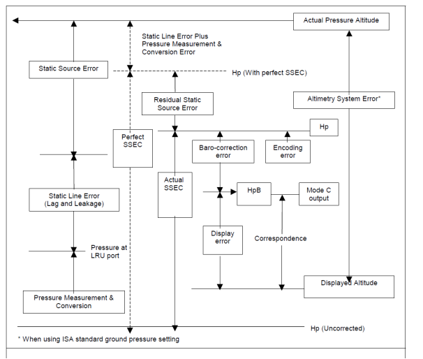
FIGURE 1 - Altimetry system errors
3.2 Components
Each of the system errors presented in Figure 1 and described in (c)(1) is discussed below in greater detail.
3.2.1 Static Source Error
The component parts of SSE are presented in Table 1, with the factors that control their magnitude.
(a) The reference SSE is the best estimate of actual SSE, for a single aircraft or an aircraft group, obtained from flight calibration measurements. It is variable with operating condition, characteristically reduced to a family of W/δ curves that are functions of Mach.
It includes the effect of any aerodynamic compensation that may have been incorporated in the design. Once determined, the reference SSE is fixed for the single aircraft or group, although it may be revised when considering subsequent data.
(b) The test techniques used to derive the reference SSE will have some measurement of uncertainty associated with them, even though known instrumentation errors will normally be eliminated from the data. For trailing-cone measurements the uncertainty arises from limitations on pressure measurement accuracy, calibration of the trailing-cone installation, and variability in installations where more than one are used. Once the reference SSE has been determined, the actual measurement error is fixed, but as it is unknown it can only be handled within the ASE budget as an estimated uncertainty.
(c) The airframe variability and probe/port variability components arise from differences between the individual airframe and probe/port, and the example(s) of airframe and probe port used to derive the reference SSE.
3.2.2 Residual Static Source Error
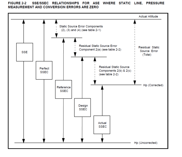
(a) The components and factors are presented in Table 1. Residual SSE is made up of those error components which make actual SSE different from the reference value, components 2, 3, and 4 from Table 1, plus the amount by which the actual SSEC differs from the value that would correct the reference value exactly, components 2(a), (b) and(c) from Table 2.
(b) There will generally be a difference between the SSEC that would exactly compensate the reference SSE, and the SSEC that the avionics is designed to apply. This arises from practical avionics design limitations. The resulting error component 2(a) will therefore be fixed, for a particular flight condition, for the single aircraft or group. Additional variable errors 2(b) and 2(c) arise from those factors that cause a particular set of avionics to apply an actual SSEC that differs from its design value.
(c) The relationship between perfect SSEC, reference SSEC, design SSEC and actual SSEC is illustrated in Figure 2, for the case where static line errors and pressure measurements and conversion errors are taken as zero.
(d) Factors that create variability of SSE relative to the reference characteristic should be accounted for twice. First, as noted for the SSE itself in Table 2, and secondly for its effect on the corruption of SSEC as in factor 2(a)(i) of Table 2. Similarly the static pressure measurement error should be accounted for in two separate ways. The main effect will be by way of the 'pressure measurement and conversion' component, but a secondary effect will be by way of factor 2(a)(ii) of Table 2.
|
Factors |
Error Components |
|
Airframe Effects |
|
|
Operating Condition (Speed, altitude, angle of attack, sideslip) |
1) |
|
Geometry: Size and shape of airframe; Location of static sources; Variations of surface contour near the sources; Variations in fit of nearby doors, skin panels or other items. |
2) Uncertainty of flight calibration measurements.
|
|
Probe/Port Effects |
3) Airframe to airframe variability. |
|
Operating Condition (Speed, altitude, angle of attack, sideslip) |
|
|
Geometry: Shape of probe/port; Manufacturing variations; Installation variations. |
4) Probe/port to probe/port variability. |
TABLE 1 - Static source error
(Cause: Aerodynamic Disturbance to Free-Stream Conditions)
|
Factors |
Error Components |
|
(1) As for Static Source Error PLUS |
1) Error Components (2), (3), and (4) from table 2-1 PLUS |
|
(2) Source of input data for SSEC function |
2(a) Approximation in fitting design SSEC to flight calibration reference SSE. |
|
(a) Where SSEC is a function of Mach: |
|
|
(i) PS sensing: difference in SSEC from reference SSE. (ii) PS measurement: pressure transduction error. (iii) PT errors: mainly pressure transduction error. |
2(b) Effect of production variability (sensors and avionics) on achieving design SSEC.
2(c) Effect of operating environment (sensors and avionics) on achieving design SSEC. |
|
(b) Where SSEC is a function of angle of attack: |
|
|
(i) geometric effects on alpha: - sensor tolerances; - installation tolerances; - local surface variations. (ii) measurement error: - angle transducer accuracy. |
|
|
(3) Implementation of SSEC function |
|
|
(a) Calculation of SSEC from input data; (b) Combination of SSEC with uncorrected height. |
|
TABLE 2 - Residual static source error: (aircraft with avionic SSEC)
(Cause: Difference between the SSEC actually applied and the actual SSE)
3.2.3 Static Line Error
Static line errors arise from leaks and pneumatic lags. In level cruise these can be made negligible for a system that is correctly designed and correctly installed.
3.2.4 Pressure Measurement and Conversion Error
(a) The functional elements are static pressure sensing, which may be mechanical, electromechanical or solid-state, and the conversion of pressure signal to pressure altitude.
(b) The error components are:
(i) calibration uncertainty;
(ii) nominal design performance;
(iii) unit to unit manufacturing variations; and
(iv) effect of operating environment.
(c) The equipment specification is normally taken to cover the combined effect of the error components. If the value of pressure measurements and conversion error used in the error budget is the worst case specification value, then it is not necessary to assess the above components separately. However, calibration uncertainty, nominal design performance and effect of operating environment can all contribute to bias errors within the equipment tolerance. Therefore, if it is desired to take statistical account of the likely spread of errors within the tolerance band, then it will be necessary to assess their likely interaction for the particular hardware design under consideration.
(d) It is particularly important to ensure that the specified environmental performance is adequate for the intended application.
3.2.5 Baro-Setting Error
This is the difference between the value displayed and the value applied within the system. For RVSM operation the value displayed should always be the International Standard Atmosphere ground pressure, but setting mistakes, although part of TVE, are not components of ASE.
(a) The components of Baro-Setting Error are:
(i) resolution of setting knob/display;
(ii) sensing of displayed value; and
(iii) application of sensed value.
(b) The applicability of these factors and the way that they combine depend on the particular system architecture.
(c) For systems in which the display is remote from the pressure measurement function there may be elements of the sensing and/or application or sensed value error components which arise from the need to transmit and receive the setting between the two locations.
3.2.6 Display Error
The cause is imperfect conversion from altitude signal to display.
The components are:
(a) conversion of display input signal;
(b) graticule/format accuracy, and
(c) readability.
Note: In self-sensing altimeters the first of these would normally be separate from the pressure measurement and conversion error.
Appendix B – Examples of methods to establish and monitor static‑source errors (group aircraft only)
ED Decision 2022/008/R
1 Introduction
Two examples showing the method establish and monitor static source errors are presented below.
2 Example 1
One process for showing compliance with RVSM criteria is shown in Figure 1. Figure 1 illustrates how those flight test calibrations and geometric inspections will be performed on a given number of aircraft. The flight calibrations and inspections will continue until a correlation between the two is established. Geometric tolerances and SSEC will be established to satisfy RVSM criteria. For aircraft being manufactured, every Nth aircraft will be inspected in detail and every Mth aircraft will be flight test calibrated, where 'N' and 'M' are determined by the aircraft constructor and agreed to by the competent authority.
The data generated by 'N' inspections and 'M' flight calibrations can be used to track the mean and three standard deviation values to ensure continued compliance of the model with the criteria of CS ACNS.E.RVSM.035.
As additional data are acquired, they should be reviewed to determine if it is appropriate to change the values of N and M as indicated by the quality of the results obtained.
There are various ways in which the flight test and inspection data might be used to establish the correlation. The example shown in Figure 2 is a process in which each of the error sources for several aeroplanes is evaluated based on bench tests, inspections and analysis. Correlation between these evaluations and the actual flight test results would be used to substantiate the method.
The method illustrated in Figures 1 and 2 is appropriate for new models since it does not rely on any pre-existing data base for the group.
3 Example 2
Figure 3 illustrates that flight test calibrations should be performed on a given number of aircraft and consistency rules for air data information between all concerned systems verified. Geometric tolerances and SSEC should be established to satisfy the criteria. A correlation should be established between the design tolerances and the consistency rules. For aircraft being manufactured, air data information for all aircraft should be checked for consistency in cruise conditions and every Mth aircraft should be calibrated, where M is determined by the manufacturer and agreed to by the responsible authority. The data generated by the M flight calibrations should be used to track the mean and three standard deviation values to ensure continued compliance of the group with the criteria of CS ACNS.E.RVSM.035.
 Figure 1 - Process for showing initial and continued compliance of airframe static pressure systems
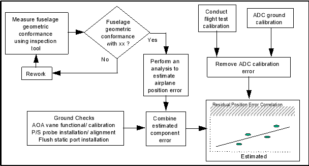 Figure 2 - Compliance demonstration ground - to flight test correlation process example
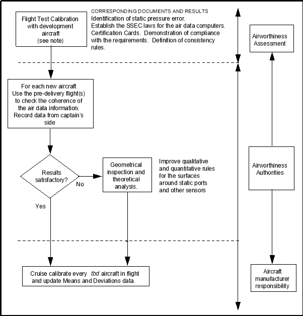 Figure 3 - Process for showing initial and continued compliance of airframe static pressure systems for new model aircraft.
Note: The flight test installation chosen to get the calibration data will need to have an accuracy compatible with the level of performance to be demonstrated and an analysis of this accuracy will need to be provided. Any possible degradation of this accuracy will need to be monitored and corrected during the flight test period.
[Issue: CS-ACNS/4]