
CS ACNS.C.PBN.101 Applicability
ED Decision 2019/011/R
(See AMC1 ACNS.C.PBN.101, GM1 ACNS.C.PBN.101 and GM2 ACNS.C.PBN.101)
(a) Table 1 indicates the applicable airworthiness requirements to be met by the airborne RNP system installation in order to obtain airworthiness approval for the RNP specifications addressed in this CS. Applicants should select the target PBN specification from the left column and then follow the respective row to the right.
(b) Subsection 2 provides also certification criteria for RNAV 10, RNAV 5, RNAV 2 and RNAV 1.
(c) The RNP 0.3 specification is applicable to helicopters.
Table 1: PBN specifications — Mandatory and optional airworthiness requirements
|
Basic criteria |
Supplementary criteria |
||||||||
|
PBN specification |
Subsections LNAV |
Subsection LNAV in final approach |
Subsection VNAV |
Subsection VNAV in final approach |
Subsection RNP AR |
Subsection Advanced-RNP |
Subsection RF |
Subsection FRT |
Subsection
Parallel |
|
RNP 4 |
Required |
|
|
|
|
|
|
Optional |
Required |
|
RNP 2 |
Required |
|
|
|
|
|
|
Optional |
Optional |
|
RNP 1 |
Required |
|
Optional |
|
|
|
Optional |
|
|
|
RNP 0.3 |
Required |
|
Optional |
|
|
|
Optional |
|
|
|
RNP APCH |
Required |
Required |
Optional |
Required |
|
|
Optional |
|
|
|
RNP AR |
Required |
Required |
Required |
Required |
Required |
|
Required |
|
|
|
A-RNP |
Required |
Required |
Optional |
Required |
|
Required |
Required |
Optional |
Required |
Subsection 1: General applicability for performance-based lateral navigation
Subsection 2: Generic specifications for performance-based lateral navigation
Subsection 3: Supplementary specifications for lateral navigation in final approach
Subsection 4: Supplementary specifications for vertical navigation
Subsection 5: Supplementary specifications for vertical navigation in final approach
Subsection 5 includes criteria for RNP APCH approaches to LNAV/VNAV minima, either supported by barometric VNAV or by SBAS VNAV, as well as for RNP APCH approaches to LPV minima, which are supported by SBAS VNAV only. An applicant may opt to apply for approval of the RNP system to conduct operations to LNAV/VNAV minima, LPV minima or both.
Subsection 6: Supplementary specifications for RNP authorisation required (AR)
Subsection 6 includes criteria for RNP AR APCH and RNP AR departures. An applicant may opt to only apply for approval for RNP AR APCH.
Subsection 7: Supplementary specifications for applications for advanced RNP (A-RNP)
Subsection 8: Supplementary specifications supporting radius to fix (RF)
Subsection 9: Supplementary specifications supporting fixed radius transition (FRT)
Subsection 10: Supplementary specifications supporting parallel offset
[Issue: CS-ACNS/2]
AMC1 ACNS.C.PBN.101 Applicability
ED Decision 2019/011/R
RNAV certification is granted as follows:
(a) Aircraft that comply with the requirements of Subsection 2 comply with all the criteria of the RNAV 1, RNAV 2, and RNAV 5 specifications.
(b) Aircraft equipped with dual multi-sensor RNP systems which integrate inertial position source(s) that meet the criteria of Appendix B and which conform to the requirements of Subsection 2 comply with the criteria of the RNAV 10 specification.
(c) Aircraft that are equipped with dual stand-alone RNP systems with integrated GNSS sensors that comply with the requirements of Subsection 2, comply with the criteria of the RNAV 10 specification if the AFM (or equivalent) contains a requirement stating that:
— an approved fault detection and exclusion (FDE) availability-prediction program is used, and;
— the maximum allowable time for which FDE capability is projected to be unavailable is 34 minutes for any one occasion.
[Issue: CS-ACNS/2]
GM1 ACNS.C.PBN.101 Applicability
ED Decision 2019/011/R
Subpart C of CS-ACNS provides certification criteria for performance-based navigation. EASA has considered the current and future aircraft equipment and has assumed that most, if not all, aircraft are equipped with one or more GNSS receivers. Subpart C, therefore, considers GNSS equipped aircraft and focuses on compliance with RNP navigation specifications. Compliance with Subsection 2, however, also assures compliance with the RNAV 10, RNAV 5, RNAV 2, and RNAV 1 navigation specifications.
Where the term ‘Required’ is used in Table 1, it refers to compliance with the navigation specification.
It should be noted that for multi-sensor RNP systems, loss of RNP capability does not imply loss of RNAV capability if an inertial or DME navigation source(s) is(are) still operable.
It should be noted that this Subpart does not address communication and surveillance considerations that are, in some cases, related to the implementation of a navigation specification (e.g. controller-pilot data link communications (CPDLC) and automatic dependent surveillance — contract (ADS-C) for RNP 4) within a particular airspace.
The ICAO PBN Manual (Doc 9613) contains 11 navigation specifications, each of them addressing specific operations by flight phase:
(a) RNAV 10, historically referred to as RNP 10, is applied for oceanic and remote continental navigation operations;
(b) RNAV 5, RNAV 2 and RNAV 1 are applied for continental en-route and terminal navigation operations;
(c) RNP 4 and RNP 2 and A-RNP are applied for oceanic and remote continental navigation operations;
(d) RNP 2 and A-RNP are applied for continental en-route navigation operations;
(e) RNP 1 and A-RNP are applied for terminal navigation operations;
(f) A-RNP, RNP APCH, and RNP AR APCH are applied for initial, intermediate, final, and missed approach navigation operations, and may include requirements for vertical navigation (VNAV);
(g) RNP 0.3 was specifically written to facilitate (low-level) en-route operations with rotorcraft.
Subpart C on performance-based navigation contains basic and supplemental certification criteria. The basic criteria must always be complied with, regardless of the navigation specification, and ensure compliance with the navigational requirements of the RNAV 10, RNAV 5, RNAV 2, RNAV 1, RNP 2, RNP 1 and RNP 0.3 criteria.
Some navigation specifications require compliance with supplemental criteria, e.g. compliance with Subsection 10 for parallel offsets for RNP 4.
The criteria for navigation specifications that include approach, i.e. A-RNP, RNP APCH and RNP AR, are more specific. Subsection 3 (‘LNAV in final approach’) and Subsection 5 (‘VNAV in final approach’) apply to these operations. In addition, both RNP AR and A-RNP have their own specific criteria that need to be met, as described in Subsection 6 for RNP AR and Subsection 7 for A-RNP.
Subsection 4 addresses vertical navigation (VNAV) outside the final approach part of the flight. It contains criteria for compliance with altitude constraints considered in Commission Implementing Regulation (EU) 2018/1048.
In addition to the criteria for RNP APCH approaches, Subsection 5 also contains optional requirements for advisory VNAV, which apply to the final approach segment (FAS) only.
Subsections 8, 9, and 10 contain criteria for specific functions. These functions (radius to fix, fixed radius transition, and parallel offset) are required for some applications and are optional for some others.
In some instances, the CS requirements deviate from the ICAO navigation specification, for example by requiring VNAV for RNP APCH. This is based on recent certification experience, the fact that CS-ACNS is a forward-looking document that is based on the latest ICAO and industry standards, and it is also a consequence of the way Section 1 has been structured. Where applicants intent to strictly apply the criteria of the ICAO navigation specification, they are invited to consult EASA (e.g. an applicant applying for RNP APCH without VNAV down to LNAV minima or LP minima only).
Applicants intending to apply strictly for RNAV navigation specifications predicated on conventional ground navigation aids, i.e. non-GNSS-based navigation, are also invited to consult EASA.
Example application of Table 1:
Question: An applicant wishes to apply for certification of an aircraft for RNP APCH. Which subsections of Subpart C should the applicant demonstrate compliance with?
Answer: Subsections 1 and 2, and the supplemental and the more stringent criteria provided in Subsections 3 and 5 for lateral and vertical navigation, respectively. The applicant may need to also demonstrate compliance with Subsection 8, which is optional, as the RF functionality could be used in the initial and intermediate approach segments, and in the final phase of the missed approach.
Additionally, Appendix C to Subpart C provides guidance material for the installation of equipment constituting the aircraft’s RNP system and for testing the aircraft’s RNP system.
[Issue: CS-ACNS/2]
GM2 ACNS.C.PBN.101 Applicability
ED Decision 2019/011/R
With the publication of CS-ACNS, AMC 20-4A, AMC 20-5, AMC 20-12, AMC 20-26, AMC 20-27A, AMC 20-28, JAA TGL-10 and CM-AS-002 Issue 2 have become obsolete. This, however, does not invalidate existing approvals to these references.
Changes to aircraft/systems that were approved to the above AMC-20 references or TGL will be handled as follows:
— Where the change remains within the original scope of the AMC or TGL, i.e. no new functionality is added, the applicant may continue to use the criteria of the AMC or TGL as the certification basis for the change.
— Where the change is outside the original scope of the AMC or TGL, i.e. a new functionality is added, the corresponding certification criteria in CS-ACNS are to be applied. Given the differences in the set‑up of the AMC/TGL compared to CS-ACNS, an applicant may, within reason, claim credit for items already demonstrated to an AMC or TGL that are similar to the requirements in CS‑ACNS.
Examples:
1) An aircraft has been approved to perform RNP AR operations to the criteria of AMC 20-26. The applicant is updating the software of the flight management system, but no additional functionality is being added. In that case, the criteria of AMC 20-26 continue to be applicable.
2) An aircraft has been approved to conduct RNP APCH operations to LNAV or LNAV/VNAV using barometric VNAV in accordance with AMC 20-27A. The applicant is replacing the GNSS receiver with one that can receive differential correction signals from a satellite based augmentation system (SBAS) and adds the capability to operate on RNP APCH approach procedures to LP or LPV minima. This capability was not within the original scope of AMC 20-27A. The applicant should, therefore, apply the criteria of the new CS-ACNS. Credit may be claimed for items already demonstrated as part of the compliance demonstration to AMC 20-27A, where these may be considered to be reasonably similar and applicable.
[Issue: CS-ACNS/2]
CS ACNS.C.PBN.201 Applicability
ED Decision 2019/011/R
Subsection 2 provides the functional and performance criteria that are common to all PBN specifications for lateral navigation.
[Issue: CS-ACNS/2]
SYSTEM QUALIFICATION CRITERIA
CS ACNS.C.PBN.205 RNP system approval
ED Decision 2019/011/R
(See AMC1 ACNS.C.PBN.205, AMC2 ACNS.C.PBN.205, GM1 ACNS.C.PBN.205, GM2 ACNS.C.PBN.205 and GM3 ACNS.C.PBN.205)
All equipment contributing to the area navigation function is approved.
[Issue: CS-ACNS/2]
AMC1 ACNS.C.PBN.205 RNP system approval
ED Decision 2019/011/R
For all navigation specifications except RNP 0.3:
(a) where the RNP system architecture is based on a stand-alone system, the RNP system should be granted a European Technical Standard Order (ETSO) authorisation against the following ETSO:
(1) ETSO-C146c (operational Class 3).
(2) ETSO-C190 active antenna.
(b) where the RNP system architecture is based on a flight management system (FMS) receiving input from various sources of position, the FMS should be granted an ETSO authorisation against ETSO-C115d and, depending on the type of sources to determine position, these should be granted an ETSO authorisation against the following ETSO or be compliant with the following standards:
(1) GNSS position source against ETSO-C196a or ETSO-C145c (operational Class 3);
(2) GNSS antenna against:
(i) ETSO-C144a passive antenna when an ETSO-C196a GNSS position source is installed, or;
(ii) ETSO-C190 active antenna when an ETSO-C196a or ETSO-C145c GNSS position source is installed.
(3) DME/DME horizontal position source based on a DME interrogator that has been granted an ETSO authorisation against ETSO-2C66b;
(4) barometric altimeter: ETSO-C106 Amendment 1.
(c) with reference to CS ACNS.A.GEN.020, any deviations from the ETSOs should be evaluated against the relevant sections of EUROCAE ED-75D Minimum Aviation System Performance Standard (MASPS).
(d) noting that there is no equipment standard for INS/IRU horizontal position source, this equipment should comply with the functionality and performance that is detailed in Appendix B.
[Issue: CS-ACNS/2]
AMC2 ACNS.C.PBN.205 RNP system approval
ED Decision 2019/011/R
For compliance with the RNP 0.3 navigation specification, the RNP system is supported by an SBAS capable GNSS position source, i.e. one that has been authorised against ETSO-C145c (operational Class 3) or ETSO‑C146c (operational Class 3).
[Issue: CS-ACNS/2]
AMC3 ACNS.C.PBN.205 RNP system approval
ED Decision 2019/011/R
Where AMC to Section 1 of Subpart C contain a reference to the criteria of EUROCAE Document ED-75D, these criteria are considered to be means to comply with the related CSs. Therefore, these criteria may be applied instead of installing ETSO-authorised equipment.
Where AMC to Section 1 of Subpart C contain a reference to a specific amendment to an ETSO, it indicates the minimum acceptable standard, so any subsequent amendments are also considered to be acceptable.
[Issue: CS-ACNS/2]
GM1 ACNS.C.PBN.205 RNP system approval
ED Decision 2019/011/R
Subpart C of CS-ACNS is based on EUROCAE ED-75D (RTCA DO-236C and Change 1), except for RNP AR, and on the ICAO PBN Manual (Doc 9613).
The AMC to Subpart C requirements encourage the installation of ETSO-authorised equipment, recognising the fact that many of the EUROCAE ED-75D requirements are covered through compliance with ETSO requirements. Recognition of ETSO authorisation generally limits the burden on the applicant that demonstrates compliance with the CS requirements.
[Issue: CS-ACNS/2]
GM2 ACNS.C.PBN.205 RNP system approval
ED Decision 2019/011/R
ETSO-C145c and ETSO-C146c (operational Class 3) support the following operations:
(a) oceanic/remote en route;
(b) continental en route;
(c) arrival;
(d) approach down to LNAV minima;
(e) approach down to LNAV/VNAV minima;
(f) approach down to LP minima;
(g) approach down to LPV minima; and
(h) departure;
ETSO-C146c (functional Class D, operational Class 4) only supports approach down to LP and LPV minima and is, therefore, only recognised as AMC for lateral navigation in final approach (see AMC1 ACNS.C.PBN.305).
The minimum system requirements may also depend on the intended airspace to be flown; hence, carriage of additional navigation systems could be required.
[Issue: CS-ACNS/2]
GM3 ACNS.C.PBN.205 RNP system approval
ED Decision 2019/011/R
Integrated GNSS/INS position solutions reduce the rate of degradation after loss of position updating. For ‘tightly coupled’ GNSS/IRUs, RTCA Document DO-229D, Appendix R, and RTCA Document DO-316, Appendix R, provide additional guidance on ‘tightly coupled’ GNSS/IRUs.
[Issue: CS-ACNS/2]
CS ACNS.C.PBN.210 Position source
ED Decision 2019/011/R
(See AMC1 ACNS.C.PBN.210)
The RNP system uses GNSS as the primary source of horizontal position.
[Issue: CS-ACNS/2]
AMC1 ACNS.C.PBN.210 Position source
ED Decision 2019/011/R
If other horizontal position sources are available, they may be used to complement the GNSS-computed position, provided that the output position continues to meet the required performance.
If the position is no longer available from a GNSS position source and if additional sources are available, the system should revert to the best available source (e.g. the source that can provide the best computed position in terms of accuracy and integrity).
Installation of equipment with an ETSO authorisation against ETSO-C115d satisfies the requirement.
[Reference: ED-75D § 3.7.3.1.2]
[Issue: CS-ACNS/2]
FUNCTIONAL CRITERIA
RNP system
CS ACNS.C.PBN.215 Position estimation
ED Decision 2019/011/R
(See AMC1 ACNS.C.PBN.215 and GM1 ACNS.C.PBN.215)
The RNP system continuously estimates:
(a) the present lateral position of the aircraft; and
(b) the accuracy and integrity of the lateral position, when supported by the navigation sensors.
[Issue: CS-ACNS/2]
AMC1 ACNS.C.PBN.215 Position estimation
ED Decision 2019/011/R
Installation of equipment with an ETSO authorisation against ETSO-C115d or ETSO-C146c (operational Class 3) satisfies the requirement.
[Reference: ED-75D § 3.1.1.1]
[Issue: CS-ACNS/2]
GM1 ACNS.C.PBN.215 Position estimation
ED Decision 2019/011/R
The estimated lateral position accuracy is a measure that is based on a defined scale, in nautical miles, which conveys the current position estimation performance. The lateral position accuracy can be related to the required navigation performance (RNP) value.
[Issue: CS-ACNS/2]
CS ACNS.C.PBN.220 Navigation source selection and reversion
ED Decision 2019/011/R
(See AMC1 ACNS.C.PBN.220)
When a multi-sensor RNP system is installed, it has the capability to automatically, or manually, select the best available navigation source(s).
[Issue: CS-ACNS/2]
AMC1 ACNS.C.PBN.220 Navigation source selection and reversion
ED Decision 2019/011/R
Installation of equipment with an ETSO authorisation against ETSO-C115d satisfies the requirement.
[Reference: ED-75D § 3.7.3.1]
[Issue: CS-ACNS/2]
CS ACNS.C.PBN.225 Reasonableness check of distance-measuring equipment (DME)
ED Decision 2019/011/R
(See AMC1 ACNS.C.PBN.225)
When the RNP system uses DME, it has the capability to perform a reasonableness check of the radio navigation data.
[Issue: CS-ACNS/2]
AMC1 ACNS.C.PBN.225 Reasonableness check of distance-measuring equipment (DME)
ED Decision 2019/011/R
Installation of equipment with an ETSO authorisation against ETSO-C115d satisfies the requirement.
[Reference: ED-75D § 3.7.3.1.1]
[Issue: CS-ACNS/2]
CS ACNS.C.PBN.230 Flight plan management
ED Decision 2019/011/R
(See AMC1 ACNS.C.PBN.230)
The RNP system provides flight crew with the capability to create, review, modify and activate a flight plan. Activation of any new flight plan or modification of an existing flight plan requires a positive action by the flight crew. Guidance output is not affected until the flight plan or its modification is activated. Once the plight plan is activated, the RNP system has the capacity to execute it.
[Issue: CS-ACNS/2]
AMC1 ACNS.C.PBN.230 Flight plan management
ED Decision 2019/011/R
(a) The RNP system should be capable of displaying:
(1) the along-track distance between any flight plan waypoints;
(2) the distance to go to any waypoint selected by the flight crew; and
(3) the actual waypoint and the data that defines it.
(b) The RNP system should enable modification of any flight plan, or flight plan segment, including procedures that were loaded from the on-board navigation database. However, FAS data blocks protected by a cyclic redundancy check (CRC) code can never be modified.
(c) The RNP system should allow the creation and insertion of pilot-defined fixes and related data.
Installation of equipment with an ETSO authorisation against ETSO-C115d is considered to meet the criteria of (b), and (c). It also supports item (a); however, the applicant should ensure the flight deck interface complies with this CS.
Installation of equipment with an ETSO authorisation against ETSO-C146c (operational Class 3) is considered to meet the criteria of (a) through (d).
[Reference: ED-75D § 3.7.2.1.1.1]
[Issue: CS-ACNS/2]
CS ACNS.C.PBN.235 Automatic leg sequencing
ED Decision 2019/011/R
(See AMC1 ACNS.C.PBN.235)
The RNP system has the capability to automatically sequence legs and display the sequencing to the flight crew in a readily visible manner.
[Issue: CS-ACNS/2]
AMC1 ACNS.C.PBN.235 Automatic leg sequencing
ED Decision 2019/011/R
Installation of equipment with an ETSO authorisation against ETSO-C115d and ETSO-C146c satisfies the requirement.
[Reference: ED-75D § 3.7.2.1.4]
[Issue: CS-ACNS/2]
CS ACNS.C.PBN.240 Route/procedure extraction and loading
ED Decision 2019/011/R
(See AMC1 ACNS.C.PBN.240)
The RNP system has the capability to extract routes/procedures from the on-board navigation database in their entirety, including all their characteristics, and to load them into the RNP system’s flight plan.
[Issue: CS-ACNS/2]
AMC1 ACNS.C.PBN.240 Route/procedure extraction and loading
ED Decision 2019/011/R
Installation of equipment with an ETSO authorisation against ETSO-C115d satisfies the requirement.
The installation of equipment with an ETSO authorisation against ETSO-C146c satisfies the CS requirement, provided that the applicant ensures that speed constraints are extracted from the database.
[Reference: ED-75D § 3.7.2.1.1.1]
[Issue: CS-ACNS/2]
CS ACNS.C.PBN.245 Path definition and leg transition
ED Decision 2019/011/R
(See AMC1 ACNS.C.PBN.245 and GM1 ACNS.C.PBN.245)
(a) The RNP system allows flight crew to define the flight path for the intended route.
(b) The RNP system has the capability to execute leg transitions and maintain tracks consistent with the following path terminators:
(1) direct to fix (DF), track to a fix (TF), initial fix (IF), fix to an altitude (FA), and course to a fix (CF);
(2) heading to an altitude (VA), heading to a manual termination (VM), and heading to an intercept (VI);
(3) course to an altitude (CA), and from a fix to a manual termination (FM).
(c) The RNP system has the capability to execute fly-by turns.
(d) Unless otherwise specified in the on-board navigation database, the RNP system constructs the flight path between waypoints in the same manner as a TF leg.
[Issue: CS-ACNS/2]
AMC1 ACNS.C.PBN.245 Path definition and leg transition
ED Decision 2019/011/R
Installation of equipment with an ETSO authorisation against ETSO-C115d satisfies the requirements.
Installation of equipment with an ETSO authorisation against ETSO-C146e satisfies the requirements.
Installation of equipment with an ETSO authorisation against ETSO-C146c satisfies the requirements of (a), (b)(1), (c) and (d).
Subject to EASA’s agreement, where the RNP system does not support the execution of VA, VM, and VI path terminators, the applicant may demonstrate that the aircraft and flight systems allow the flight crew to manually fly the aircraft on a heading to intercept a course or to go direct to another fix after reaching a procedure-specified altitude. The manual execution of VA, VM and VI terminators should be supported by a flight crew workload assessment.
Subject to EASA’s agreement, where the RNP system does not support the execution of CA and FM path terminators, the applicant may demonstrate that the RNP system allows the flight crew to readily designate a waypoint and select a desired course to or from a designated waypoint. The manual execution of CA and FM terminators should be supported by a flight crew workload assessment.
[References: ED-75D § 3.2.1.2 and ED-75D § 3.2.5.4]
[Issue: CS-ACNS/2]
GM1 ACNS.C.PBN.245 Path definition and leg transition
ED Decision 2019/011/R
(a) The intent of CS ACNS.C.PBN.245(d) is to ensure a smooth transition.
(b) Path terminators and leg transitions are defined in Aeronautical Radio, Inc. (ARINC) 424 documents, and their application is described in more detail in EUROCAE ED-75D, and ED-77 (RTCA documents DO‑236C Change 1, and DO-201A).
[Issue: CS-ACNS/2]
CS ACNS.C.PBN.250 ‘Direct-to’ function
ED Decision 2019/011/R
(See AMC1 ACNS.C.PBN.250)
The RNP system has the capability to generate and execute a geodesic path to any designated fix, at any time, without ‘S-turning’ and without undue delay, known as ‘direct-to’ function.
[Issue: CS-ACNS/2]
AMC1 ACNS.C.PBN.250 ‘Direct-to’ function
ED Decision 2019/011/R
Installation of equipment with an ETSO authorisation against ETSO-C115d or ETSO-C146c satisfies the requirement.
[Reference: ED-75D § 3.2.4.2]
[Issue: CS-ACNS/2]
CS ACNS.C.PBN.255 Magnetic variation
ED Decision 2022/008/R
(See AMC1 ACNS.C.PBN.255)
(a) The required navigation performance (RNP) system has the capability to assign a magnetic variation at any location within the region where flight operations are conducted, using the magnetic north as reference.
(b) For paths defined by a course, the RNP system uses the appropriate magnetic variation value available in the navigation database.
(c) The conditions under which the magnetic variation table (MAGVAR table), certified as part of the aircraft configuration, is updated are included in the aircraft’s instructions for continued airworthiness (ICAs).
[Issue: CS-ACNS/2]
[Issue: CS-ACNS/4]
AMC1 ACNS.C.PBN.255 Magnetic variation
ED Decision 2019/011/R
Installation of equipment with an ETSO authorisation against ETSO-C115d or ETSO-C146c satisfies the requirement of (a) and (b).
[Reference: ED-75D § 3.2.5.2]
[Issue: CS-ACNS/2]
CS ACNS.C.PBN.260 RNAV holding
ED Decision 2019/011/R
(See AMC1 ACNS.C.PBN.260 and GM1 ACNS.C.PBN.260)
(a) The RNP system has the capability to initiate, maintain and discontinue holding procedures at any point and at all altitudes. When a holding procedure is initiated, the RNP system:
(1) permits the flight crew to readily select a desired course to the holding waypoint;
(2) retains all subsequent waypoints in the active flight plan in the same sequence; and
(3) permits the flight crew to readily initiate the return to automatic waypoint sequencing at any time and continue with the existing flight plan.
(b) The RNP system allows for manual or automatic definition of the holding pattern.
[Issue: CS-ACNS/2]
AMC1 ACNS.C.PBN.260 RNAV holding
ED Decision 2019/011/R
Installation of equipment with an ETSO authorisation against ETSO-C115d satisfies the requirement, provided that the equipment meets the criteria defined in RTCA DO-283B § 2.2.1.2.6.
Installation of equipment with an ETSO authorisation against ETSO-C146c satisfies the requirement.
[Reference: ED-75D § 3.7.2.2.3.1]
[Issue: CS-ACNS/2]
GM1 ACNS.C.PBN.260 RNAV holding
ED Decision 2019/011/R
The intent of the CS is to require RNAV holding, not RNP holding.
[Issue: CS-ACNS/2]
CS ACNS.C.PBN.265 User-defined routes and fixes
ED Decision 2019/011/R
(See AMC1 ACNS.C.PBN.265 and GM1 ACNS.C.PBN.265)
The RNP system provides means for the flight crew to build a user-defined route by:
(a) entering unique waypoints extracted from the on-board navigation database; and
(b) manually creating user-defined fixes.
[Issue: CS-ACNS/2]
AMC1 ACNS.C.PBN.265 User-defined routes and fixes
ED Decision 2019/011/R
Installation of equipment with an ETSO authorisation against ETSO-C115d or ETSO-C146c satisfies the requirement.
[References: ED-75D § 3.7.2.1.2.1 & ED-75D § 3.7.2.1.2.2]
[Issue: CS-ACNS/2]
GM1 ACNS.C.PBN.265 User-defined routes and fixes
ED Decision 2019/011/R
User-defined fixes are usually defined via the entry of latitude/longitude, place/along-track, place/bearing-place/bearing, and place/bearing/distance.
[Issue: CS-ACNS/2]
CS ACNS.C.PBN.270 Navigation accuracy
ED Decision 2019/011/R
(See AMC1 ACNS.C.PBN.270)
(a) The RNP system is capable of acquiring and setting the RNP value for each segment of a route or procedure.
(b) When an aircraft flies an RNP route or procedure and the RNP value changes to a lower value, the RNP completes the change no later than reaching the leg with the lower RNP value.
[Issue: CS-ACNS/2]
AMC1 ACNS.C.PBN.270 Navigation accuracy
ED Decision 2019/011/R
(a) The RNP value associated with a leg or segment should be assigned in the following order of precedence:
(1) flight crew manually entered RNP value for the leg or segment;
(2) the RNP value coded in the on-board navigation database for the current leg or segment, if implemented;
(3) the RNP value coded in the on-board navigation database for the current area, if implemented; and last
(4) a system default RNP value, if provided by the RNP system.
(b) Installation of equipment with an ETSO authorisation against ETSO-C115d or ETSO-C146c satisfies the requirement.
[References: ED-75D § 3.7.2.1.3.1, ED-75D § 3.2.6, ED-75D § 3.2.6.2]
[Issue: CS-ACNS/2]
Display of navigation data
CS ACNS.C.PBN.275 Display and entry of navigation data — resolution
ED Decision 2019/011/R
(See AMC1 ACNS.C.PBN.275)
The RNP system displays and allows manual entry of navigation data with a resolution that supports the intended operation.
[Issue: CS-ACNS/2]
AMC1 ACNS.C.PBN.275 Display and entry of navigation data — resolution
ED Decision 2019/011/R
Installation of equipment with an ETSO authorisation against ETSO-C115d or ETSO-C146c satisfies the requirement.
[Reference: ED-75D § 3.6.2]
[Issue: CS-ACNS/2]
CS ACNS.C.PBN.280 Deviation display
ED Decision 2019/011/R
(See AMC1 ACNS.C.PBN.280, AMC2 ACNS.C.PBN.280 and AMC3 ACNS.C.PBN.280)
(a) For defined paths, the RNP system continuously displays, in each flight crew’s optimum field of view, the computed path and the deviation from that path.
(b) The lateral deviation display is automatically slaved to the RNP system’s computed path.
[Issue: CS-ACNS/2]
AMC1 ACNS.C.PBN.280 Deviation display
ED Decision 2019/011/R
An acceptable means of compliance is to provide a non-numeric deviation display. The full-scale deflection of the non-numeric lateral deviation display should be:
(a) comparable with the applicable RNP value; and
(b) made available to the flight crew.
Alternatively, subject to EASA’s agreement, a moving map display with appropriate map scales, and which provides a sufficiently equivalent functionality to a non-numeric lateral deviation display, may be accepted. EASA’s agreement will be based on a human factor and workload assessment performed by the applicant.
[Issue: CS-ACNS/2]
AMC2 ACNS.C.PBN.280 Deviation display
ED Decision 2019/011/R
When used to conduct a departure procedure off the runway, the RNP system should display lateral deviations not later than when reaching 50 feet above the departure runway. Installation of equipment with an ETSO authorisation against ETSO-C115d or ETSO-C146c supports this.
[Reference: ED-75D § 3.3.3.1]
[Issue: CS-ACNS/2]
AMC3 ACNS.C.PBN.280 Deviation display
ED Decision 2019/011/R
Subject to EASA’s agreement, a lateral deviation display not slaved to the RNP system associated with adequate operational procedures may be accepted for type-certification application against RNP 2, RNP 1 or RNP APCH. The applicant should provide a human factor and workload assessment in support of the application.
Note: The alleviation provided above is intended to address particular concerns on small CS-23, Level 1, 2, and 3 aircraft.
[Issue: CS-ACNS/2]
CS ACNS.C.PBN.285 Display of active waypoint
ED Decision 2019/011/R
(See AMC1 ACNS.C.PBN.285 and AMC2 ACNS.C.PBN.285)
The RNP system displays in the flight crew’s maximum field of view:
(a) the identification of the active (To) waypoint; and
(b) the distance, estimated time of arrival at, or time-to go to, and bearing to the active (To) waypoint.
[Issue: CS-ACNS/2]
AMC1 ACNS.C.PBN.285 Display of active waypoint
ED Decision 2019/011/R
The installation of equipment with an ETSO authorisation against ETSO-C146c satisfies the CS requirement, provided that the applicant ensures that both the distance to and the estimated time of arrival at the active waypoint are available to the flight crew.
[Issue: CS-ACNS/2]
AMC2 ACNS.C.PBN.285 Display of active waypoint
ED Decision 2019/011/R
Subject to EASA’s agreement, the display of the data on a page on a multifunction control and display unit (MCDU), readily accessible to the flight crew, may be accepted for type-certification application against RNP 4 or RNP 2. EASA’s agreement will be based on a human factor and workload assessment performed by the applicant.
[Issue: CS-ACNS/2]
CS ACNS.C.PBN.290 Display of ground speed
ED Decision 2019/011/R
(See AMC1 ACNS.C.PBN.290)
The RNP system displays the ground speed in the flight crew’s maximum field of view.
[Issue: CS-ACNS/2]
AMC1 ACNS.C.PBN.290 Display of ground speed
ED Decision 2019/011/R
The installation of equipment in the flight crew’s maximum field of view with an ETSO authorisation against ETSO-C146c satisfies the requirement.
Installation of equipment with an ETSO authorisation against ETSO-C115d supports the requirement, provided that the applicant ensures that the flight deck interface complies with this CS.
[Reference: ED-75D § 3.7.5.2.1]
[Issue: CS-ACNS/2]
CS ACNS.C.PBN.2105 Display of speed constraints
ED Decision 2019/011/R
(See AMC1 ACNS.C.PBN.2105)
The RNP system displays speed constraints to the flight crew in the maximum field of view.
[Issue: CS-ACNS/2]
AMC1 ACNS.C.PBN.2105 Display of speed constraints
ED Decision 2019/011/R
Subject to EASA’s agreement, a display of speed constraints outside the maximum field of view with adequate operational procedures may be accepted. The applicant should provide a human factor and workload assessment in support of the application.
[Issue: CS-ACNS/2]
CS ACNS.C.PBN.2110 Display of navigation aid frequencies and/or identifiers
ED Decision 2019/011/R
The RNP system has the capability to display the frequencies and/or identifiers of the ground positioning navigation aids selected on a page which is readily available to the flight crew.
[Issue: CS-ACNS/2]
Navigation database
CS ACNS.C.PBN.2115 Use of navigation database
ED Decision 2019/011/R
(See AMC1 ACNS.C.PBN.2115 and GM1 ACNS.C.PBN.2115)
The RNP system uses an on-board navigation database which:
(a) is protected against flight crew modification of the stored data; and
(b) has a capacity appropriate for the intended operation.
[Issue: CS-ACNS/2]
AMC1 ACNS.C.PBN.2115 Use of navigation database
ED Decision 2019/011/R
The installation of equipment with an ETSO authorisation against ETSO-C115d or ETSO-C146C satisfies the CS requirement, provided that the applicant ensures that the database capacity is appropriate for the intended operation.
[References: ED-75D § 3.8.1, ED -75D § 3.8.2]
[Issue: CS-ACNS/2]
GM1 ACNS.C.PBN.2115 Use of navigation database
ED Decision 2019/011/R
The storage capacity is consistent with the intended use of the aircraft. For example, the database of a regional aircraft may contain data for a given region only, whereas the database of a long-range aircraft may contain worldwide data.
[Issue: CS-ACNS/2]
CS ACNS.C.PBN.2120 Data quality requirements (DQRs)
ED Decision 2019/011/R
(See AMC1 ACNS.C.PBN.2120)
The applicant ensures that the DQRs associated with the navigation database have been defined and are compatible with the intended function through formal arrangements that are signed with the corresponding data services provider(s) (DAT provider).
[Issue: CS-ACNS/2]
AMC1 ACNS.C.PBN.2120 Data quality requirements (DQRs)
ED Decision 2019/011/R
Since database process assurance levels are normally addressed at equipment design level, the applicant should verify with the equipment manufacturer that the DQRs have been established and provided to the navigation database provider(s). Formal arrangements should also ensure that deficiencies and/or errors detected by the DAT provider can be reported to the applicant, whenever DQRs could be compromised.
Documentation that these data quality requirements are valid at aircraft level must be confirmed during the airworthiness approval.
[Issue: CS-ACNS/2]
CS ACNS.C.PBN.2125 Extraction and display of navigation data
ED Decision 2019/011/R
(See AMC1 ACNS.C.PBN.2125 and GM1 ACNS.C.PBN.2125)
The RNP system has the means to:
(a) process the data with the resolution provided by the database; and
(b) enable flight crew to:
(1) verify the validity period of the on-board navigation database; and
(2) load from the on-board navigation database, by its identifier(s), the procedure(s) to be flown.
[Issue: CS-ACNS/2]
AMC1 ACNS.C.PBN.2125 Extraction and display of navigation data
ED Decision 2019/011/R
The installation of equipment with an ETSO authorisation against ETSO-C115d or ETSO-C146c satisfies the requirement.
[Reference: ED-75D § 3.8.2]
[Issue: CS-ACNS/2]
GM1 ACNS.C.PBN.2125 Extraction and display of navigation data
ED Decision 2019/011/R
The intent of CS ACNS.C.PBN.2125(a) is not to prevent truncating resolution to optimise performance as long as the truncation is commensurate with the procedure. Rather, the intent is to ensure compatibility between the database and the RNP system.
[Issue: CS-ACNS/2]
Monitoring and alerting
CS ACNS.C.PBN.2130 Alerting associated with degradation of navigation
ED Decision 2019/011/R
(See AMC1 ACNS.C.PBN.2130)
When the RNP system is unable to meet the RNP value, the RNP system provides, without undue delay, an indication in the flight crew’s optimum field of view.
[Issue: CS-ACNS/2]
AMC1 ACNS.C.PBN.2130 Alerting associated with degradation of navigation
ED Decision 2019/011/R
The alerting requirement is satisfied by installation of equipment with an ETSO authorisation against ETSO-C115d or ETSO-C146c, provided that the applicant ensures that the alert is appropriately indicated in the flight crew’s optimum field of view, and assess any processing delays caused by the aircraft flight deck alerting system.
Subject to EASA’s agreement, display of the alert in the flight crew’s maximum field of view may be accepted. The applicant should support the deviation by providing a human factor and workload assessment.
Note: The alleviation provided above is intended to address particular concerns on smaller aircraft, for example, CS-23, Level 1, 2, and 3 aircraft.
[Reference: ED-75D § 3.7.6]
[Issue: CS-ACNS/2]
CS ACNS.C.PBN.2135 Navigation accuracy alerting
ED Decision 2019/011/R
(See AMC1 ACNS.C.PBN.2135)
The RNP system provides an annunciation if a manually entered RNP value is greater than the RNP value associated with the current routes and procedures as defined in the on-board navigation database. Any subsequent reduction of the latter RNP value reinstates this annunciation.
[Issue: CS-ACNS/2]
AMC1 ACNS.C.PBN.2135 Navigation accuracy alerting
ED Decision 2019/011/R
Installation of equipment with an ETSO authorisation against ETSO-C115d satisfies the CS criteria, provided that the applicant ensures that the flight deck interface complies with the CS.
This CS is typically not relevant for equipment with an ETSO authorisation against ETSO-C146c. If this equipment provides a facility to the flight crew to enter the RNP value, then this alerting mechanism should be implemented as well.
Note: This functionality is not part of the functionalities specified in RTCA Document DO-229D (MOPS).
[Reference: ED-75D § 3.7.6.1]
[Issue: CS-ACNS/2]
PERFORMANCE CRITERIA
Lateral performance
CS ACNS.C.PBN.2140 Lateral navigation accuracy
ED Decision 2019/011/R
(See AMC1 ACNS.C.PBN.2140)
The lateral navigation accuracy provided by the RNP system supports the intended operations.
[Issue: CS-ACNS/2]
AMC1 ACNS.C.PBN.2140 Lateral navigation accuracy
ED Decision 2019/011/R
Installation of equipment with an ETSO authorisation against ETSO-C115d and ETSO-C146c satisfies the requirement.
[References ED-75D §1.7.1, §1.7.2 and §2.1.1]
[Issue: CS-ACNS/2]
CS ACNS.C.PBN.2145 RNP system design — integrity
ED Decision 2019/011/R
(See AMC1 ACNS.C.PBN.2145)
The RNP system, including position sensors, displays, etc., is designed to provide a level of integrity that supports the intended operation.
[Issue: CS-ACNS/2]
AMC1 ACNS.C.PBN.2145 RNP system design — integrity
ED Decision 2019/011/R
Guidance on the integrity (provisioning of erroneous output or display of data) of the RNP system related to lateral position or guidance is provided in Appendix A to Subpart C.
[Issue: CS-ACNS/2]
CS ACNS.C.PBN.2150 RNP system design — continuity
ED Decision 2019/011/R
(See AMC1 ACNS.C.PBN.2150)
The RNP system, including position sensors, displays, etc., is designed to provide a level of continuity that supports the intended operation.
[Issue: CS-ACNS/2]
AMC1 ACNS.C.PBN.2150 RNP system design — continuity
ED Decision 2019/011/R
Guidance on the continuity (loss of the function) of the RNP system to provide lateral position or guidance is provided in Appendix A to Subpart C.
[Issue: CS-ACNS/2]
CS ACNS.C.PBN.301 Applicability
ED Decision 2019/011/R
(See GM1 ACNS.C.PBN.301)
Subsection 3 provides the supplementary functional and performance criteria that are applicable to the lateral navigation function for the final approach segment; these criteria are necessary to obtain certification against the RNP specifications that support approach operations (i.e. A-RNP, RNP APCH and RNP AR APCH).
[Issue: CS-ACNS/2]
GM1 ACNS.C.PBN.301 Applicability
ED Decision 2019/011/R
The lateral navigation capabilities of RNP systems that are required to support initial, intermediate, and missed approach segments of an approach procedure are described in Subsection 2.
[Issue: CS-ACNS/2]
SUPPLEMENTARY FUNCTIONAL CRITERIA
RNP system
CS ACNS.C.PBN.305 RNP system approval
ED Decision 2019/011/R
(See AMC1 ACNS.C.PBN.305)
All equipment contributing to the area navigation function is approved.
[Issue: CS-ACNS/2]
AMC 1 ACNS.C.PBN.305 RNP system approval
ED Decision 2019/011/R
In addition to the systems referenced in AMC1 ACNS.C.PBN.205, equipment authorised against ETSO-C146c functional Class Delta (operational Class 4) supports operations to LP and LPV minima.
[Issue: CS-ACNS/2]
CS ACNS.C.PBN.310 Final approach intercept
ED Decision 2019/011/R
(See AMC1 ACNS.C.PBN.310 and GM1 ACNS.C.PBN.310)
The RNP system has the capability to intercept the final approach course at or before the final approach fix or the final approach point.
[Issue: CS-ACNS/2]
AMC1 ACNS.C.PBN.310 Final approach intercept
ED Decision 2019/011/R
The installation of equipment with an ETSO authorisation against ETSO-C146c Class 3 or 4 and ETSO-C115d Class A satisfies the requirement.
[Reference: ED-75D § 3.2.8.4]
[Issue: CS-ACNS/2]
GM1 ACNS.C.PBN.310 Final approach intercept
ED Decision 2019/011/R
The capability to intercept the final approach provides the pilot with the ability to capture the published final approach segment following a period when the aircraft has been flown manually, or in autopilot/automatic flight control system heading mode, following ATC vectors to support final approach sequencing.
[Issue: CS-ACNS/2]
Display of navigation data
CS ACNS.C.PBN.320 Approach mode indication
ED Decision 2019/011/R
(See GM1 ACNS.C.PBN.320)
The RNP system provides unambiguous indications in the flight crew’s maximum field of view that enables the flight crew to readily identify:
(a) the type of approach that is being flown and the applicable line of minima; and
(b) whether the guidance is angular or linear.
[Issue: CS-ACNS/2]
GM1 ACNS.C.PBN.320 Approach mode indication
ED Decision 2019/011/R
The requirement is intended to avoid confusion with regard to the type of approach procedure that is being flown and the line of minima applicable to that approach procedure, e.g. down to LNAV/VNAV minima. It is not required to actually indicate the value associated with the applicable minima.
[Issue: CS-ACNS/2]
CS ACNS.C.PBN.325 Lateral deviation display
ED Decision 2019/011/R
(See AMC1 ACNS.C.PBN.325)
The RNP system continuously displays on a non-numeric lateral deviation display, in each flight crew’s optimum field of view, the deviation from the computed path.
[Issue: CS-ACNS/2]
AMC1 ACNS.C.PBN.325 Lateral deviation display
ED Decision 2019/011/R
The deviation indicators on the non-numerical lateral display should appear in a timely fashion to allow the flight crew to intercept the final approach segment.
[Issue: CS-ACNS/2]
CS ACNS.C.PBN.330 Non-numeric lateral deviation display scaling for approach
ED Decision 2019/011/R
(See AMC1 ACNS.C.PBN.330)
The full-scale deflection of the non-numeric lateral deviation display supports the applicable track-keeping accuracy that is required for the approach.
[Issue: CS-ACNS/2]
AMC1 ACNS.C.PBN.330 Non-numeric lateral deviation display scaling for approach
ED Decision 2019/011/R
(a) When linear lateral deviation is provided, the full-scale deflection of the non-numeric deviation display should not exceed two times the RNP value.
(b) When angular lateral deviation is provided:
(1) installation of equipment with an ETSO authorisation against ETSO-C146c operational Class 3 or 4 satisfies the requirement; or
(2) the full-scale deflection of the non-numeric deviation display should allow the aircraft to remain within the two times RNP value of (a) above
[Issue: CS-ACNS/2]
CS ACNS.C.PBN.335 Display of distance to threshold
ED Decision 2019/011/R
For approaches to LPV minima, the RNP system continuously displays in the flight crew’s maximum field of view the distance to the landing threshold point/fictitious threshold point (LTP/FTP) or missed approach point (MAPt) after passing the final approach fix/final approach point.
[Issue: CS-ACNS/2]
CS ACNS.C.PBN.401 Applicability
ED Decision 2019/011/R
(See GM1 ACNS.C.PBN.401)
Subsection 4 provides the supplementary requirements that support the use of vertical navigation outside the final approach segment.
[Issue: CS-ACNS/2]
GM1 ACNS.C.PBN.401 Applicability
ED Decision 2019/011/R
(See CS ACNS.C.PBN.401)
The criteria of Subsection 4 are based on the PBN Manual, Volume II, Attachment A, and are intended to support the definition of vertical paths in airspace where vertical navigation outside the approach is intended to be applied in environments with high traffic density, traffic complexity, or terrain features, as for example those defined in the Commission Implementing Regulation (EU) 2018/1048.
[Issue: CS-ACNS/2]
SUPPLEMENTARY FUNCTIONAL CRITERIA
RNP system
CS ACNS.C.PBN.405 Vertical path
ED Decision 2019/011/R
The RNP system has the capability to define a vertical path to a fix.
[Issue: CS-ACNS/2]
CS ACNS.C.PBN.410 Altitude constraints
ED Decision 2019/011/R
(See AMC1 ACNS.C.PBN.410)
Where barometric altimetry is used as the source for vertical guidance (BARO-VNAV), the RNP system has the capability to specify a vertical path between altitude constraints at two fixes in the flight plan.
[Issue: CS-ACNS/2]
AMC1 ACNS.C.PBN.410 Altitude constraints
ED Decision 2019/011/R
The altitude constraints should be defined as follows:
(a) an ‘AT or ABOVE’ altitude constraint;
(b) an ‘AT or BELOW’ altitude constraint;
(c) an ‘AT’ altitude constraint; or
(d) a ‘WINDOW’ altitude constraint.
The installation of equipment with an ETSO authorisation against ETSO-C115d satisfies the requirement.
[Reference: ED-75D § 3.2.8.1]
[Issue: CS-ACNS/2]
CS ACNS.C.PBN.420 Pressure settings
ED Decision 2019/011/R
(See GM1 ACNS.C.PBN.420)
Where barometric altimetry is used as the source for vertical guidance (BARO-VNAV), the RNP system uses the same pressure-setting input as the aircraft’s altimetry system.
[Issue: CS-ACNS/2]
GM1 ACNS.C.PBN.420 Pressure settings
ED Decision 2019/011/R
This requirement is intended to prevent potential flight crew errors due to different altimeter settings in the aircraft altimeter system and RNP system.
[Issue: CS-ACNS/2]
CS ACNS.C.PBN.501 Applicability
ED Decision 2019/011/R
(See GM1 ACNS.C.PBN.501)
Subsection 5 provides the supplementary functional and performance criteria that are applicable to vertical navigation function for final approach.
[Issue: CS-ACNS/2]
GM1 ACNS.C.PBN.501 Applicability
ED Decision 2022/008/R
Subsection 5 sets out the certification specifications for systems that use either a barometric VNAV (BARO-VNAV) or a GNSS space-based augmented source of vertical position (SBAS-VNAV) for procedures where vertical guidance is based on a published vertical path to LNAV/VNAV or Localizer Performance with Vertical guidance (LPV) minima respectively.
The vertical performance of systems that comply with CS ACNS.C.PBN.555 is not adequate to support required navigation performance (RNP) authorisation required approach (AR APCH) operations, but the requirements contained in CS ACNS.C.PBN.670 should be applied instead.
[Issue: CS-ACNS/2]
[Issue: CS-ACNS/4]
SUPPLEMENTARY FUNCTIONAL CRITERIA
RNP system
CS ACNS.C.PBN.505 Vertical approach path
ED Decision 2019/011/R
(See GM1 ACNS.C.PBN.5015)
The RNP system has the capability to define a vertical approach path.
[Issue: CS-ACNS/2]
AMC 1 ACNS.C.PBN.505 Vertical approach path
ED Decision 2019/011/R
The installation of equipment with an ETSO authorisation against ETSO-C115d or ETSO-C146c Class 3 or 4 satisfies the requirement.
[Reference: ED-75D § 3.2.8.4.3]
[Issue: CS-ACNS/2]
CS ACNS.C.PBN.515 Pressure settings
ED Decision 2019/011/R
(See GM1 ACNS.C.PBN.515)
Where barometric VNAV is provided, the RNP system uses the same pressure-setting input as the aircraft’s altimetry system.
[Issue: CS-ACNS/2]
GM1 ACNS.C.PBN.515 Pressure settings
ED Decision 2019/011/R
This requirement is intended to prevent potential flight crew errors due to different altimeter settings in the aircraft altimeter system and RNP system.
[Issue: CS-ACNS/2]
CS ACNS.C.PBN.520 Glide path intercept
ED Decision 2019/011/R
(See AMC1 ACNS.C.PBN.520)
The RNP system has the capability to automatically intercept the final approach glide path.
[Issue: CS-ACNS/2]
AMC1 ACNS.C.PBN.520 Glide path intercept
ED Decision 2019/011/R
The RNP system should allow the glide path to be intercepted at the final approach fix (FAF) using a fly-by technique with a normal acceleration factor of not less than 0.03 g.
The installation of equipment with an ETSO authorisation against ETSO-C115d or ETSO-C146c Class 3 or 4 satisfies the requirement.
[Reference: ED-75D § 3.2.8.5]
CS ACNS.C.PBN.525 Temperature compensation
ED Decision 2019/011/R
(See AMC1 ACNS.C.PBN.525)
(a) For operations below the promulgated temperature limits on RNP APCH procedures down to LNAV/VNAV minima, area navigation systems that provide barometric VNAV apply automatic temperature compensation along the final approach segment (FAS).
(b) If the automatic temperature compensation is also provided outside the FAS of the procedure, the function providing automatic temperature compensation is pilot-selectable.
(c) Systems supporting pilot-selectable automatic temperature compensation, either within or outside of the FAS, provide a clear and distinct indication when the function is activated.
[Issue: CS-ACNS/2]
AMC1 ACNS.C.PBN.525 Temperature compensation
ED Decision 2019/011/R
The RNP system providing temperature compensation capability for the vertical path should comply with EUROCAE ED-75D, Appendix H.2.
The capability to provide automatic temperature compensation is an optional function for ETSO authorisation against ETSO C115d. Consequently, the applicant should ensure that this function has been implemented into the RNP system.
[Issue: CS-ACNS/2]
Display of navigation data
CS ACNS.C.PBN.530 Vertical deviation display
ED Decision 2019/011/R
(See AMC1 ACNS.C.PBN.530 and AMC2 ACNS.C.PBN.530)
The RNP system continuously displays, on the non-numeric vertical deviation display located in the flight crew’s optimum field of view, the deviation from the defined vertical approach path, including the extended vertical approach path.
[Issue: CS-ACNS/2]
AMC1 ACNS.C.PBN.530 Vertical deviation display
ED Decision 2019/011/R
Deviations from the defined path should be displayed in a timely fashion to support the flight crew to intercept the extended vertical approach path.
[Issue: CS-ACNS/2]
AMC2 ACNS.C.PBN.530 Vertical deviation display
ED Decision 2019/011/R
Installation of equipment with an ETSO authorisation against ETSO-C115d or ETSO-C146c supports the requirement, provided that the applicant ensures the display characteristics comply with this CS.
[Reference: ED-75D § 3.7.5.1.2.1 and § 3.7.5.1.4]
[Issue: CS-ACNS/2]
CS ACNS.C.PBN.535 Resolution and full-scale deflection of the vertical deviation display
ED Decision 2019/011/R
(See AMC1 ACNS.C.PBN.535 and GM1 ACNS.C.PBN.535)
The vertical deviation display has a resolution and a full-scale deflection that suitably supports the monitoring and bounding of the vertical deviation.
[Issue: CS-ACNS/2]
AMC1 ACNS.C.PBN.535 Resolution and full-scale deflection of the vertical deviation display
ED Decision 2022/008/R
Compliance with CS ACNS.C.PBN.535 can be demonstrated with one of the following ways:
(1) Installation of equipment with an ETSO authorisation against ETSO-C115d or ETSO-C146c supports the requirement of the CS, provided that the applicant ensures that the display characteristics comply with the CS.
(2) Required navigation performance (RNP) systems that provide fixed vertical scaling should provide a non-numerical vertical deviation display with a full-scale deflection of ± 150 ft. In addition, the display should provide the flight crew with an easy way to readily identify a path deviation of 75 ft using the vertical deviation display alone, i.e. provide clear markings at + 75 ft and at – 75 ft.
Note: Subject to EASA’s agreement, the use of a scale of other than ± 150 ft may be accepted, provided that the scaling is suitable to control the aircraft on the intended path, and the 75-ft deviation can be easily identified by the flight crew. The applicant should provide a human factors and workload assessment, as well as relevant operating procedures that ensure that the aircraft’s deviation from the path can be monitored and bounded within the ± 75-ft interval, supporting this deviation.
(3) Systems that use a type of angular vertical scaling other than the scaling defined in RTCA DO‑229D should meet the following:
(a) The deviation scaling suitably supports the flight technical error (FTE) monitoring and bounding (± 75-ft deviation);
(b) The deviation limits are equivalent to the operational limits for glideslope deviations during an ILS approach.
To meet the primary safety objective of not exceeding an FTE of 75 ft below the path to maintain obstacle clearance, it may be required to put a limitation on the length of the approach that the RNP system is able to support.
A vertical situation display is not considered to satisfy the requirements.
[Issue: CS-ACNS/2]
[Issue: CS-ACNS/4]
GM1 ACNS.C.PBN.535 Resolution and full-scale deflection of the vertical deviation display
ED Decision 2019/011/R
Vertical deviation displays that rely on the flight crew to assess the deviation based on whether or not the pointer still touches a marker are not considered acceptable. Neither does EASA consider solutions requiring the flight crew to verify the vertical deviation on a (multifunction) control display unit ((M)CDU) acceptable.
[Issue: CS-ACNS/2]
CS ACNS.C.PBN.540 Barometric altitude
ED Decision 2019/011/R
When the approach is supported by barometric VNAV, the aircraft displays the barometric altitude from two independent altimetry sources:
(a) one in each of the flight crew’s optimum field of view, if the required minimum flight crew is two; or
(b) one in the flight crew’s optimum field of view and the other visible from the flight crew’s normal position, if the required minimum flight crew is one.
[Issue: CS-ACNS/2]
CS ACNS.C.PBN.545 Active approach mode display
ED Decision 2019/011/R
If the RNP system provides both barometric VNAV and SBAS/GNSS VNAV, an unambiguous indication is provided in the flight crew’s maximum field of view that enables the flight crew to identify the active source for the VNAV, barometric altitude or SBAS/GNSS geometric altitude.
[Issue: CS-ACNS/2]
Monitoring and alerting
CS ACNS.C.PBN.550 Glide path alerting
ED Decision 2019/011/R
(See AMC1 ACNS.C.PBN.550)
For approaches to LPV minima, aircraft equipped with a Class A TAWS provide an alert for excessive deviation below the glide path.
[Issue: CS-ACNS/2]
AMC1 ACNS.C.PBN.550 Glide path alerting
ED Decision 2019/011/R
The excessive-deviation-below-the-glide-path alert may be provided by another system other than the TAWS. If this is the case, the alert should have equivalent effect to the Mode 5 alert provided by a Class A TAWS system.
Note: Applicants are highly encouraged to install a similar glide path deviation alerting function for systems that support RNP APCH down to LNAV/VNAV minima.
[Issue: CS-ACNS/2]
SUPPLEMENTARY PERFORMANCE CRITERIA
Vertical performance
CS ACNS.C.PBN.555 Vertical accuracy when using barometric VNAV
ED Decision 2019/011/R
(See AMC1 ACNS.C.PBN.555)
The accuracy of the vertical position that is provided by the RNP system when providing barometric VNAV supports the intended operations.
[Issue: CS-ACNS/2]
AMC1 ACNS.C.PBN.555 Vertical accuracy when using barometric VNAV
ED Decision 2022/008/R
When supporting VNAV, the vertical total system error (TSEZ), taking into account all the errors in the aircraft processing chain of the vertical guidance, should be lower than or equal to the values specified in the table below.
|
Altitude bands |
Level flight segments & climb/descent intercept of clearance altitudes |
Flight along specified vertical descent profile |
|
At or below 5 000 ft MSL |
150 ft |
160 ft |
|
Above 5 000 to 29 000 ft MSL |
200 ft |
210 ft |
|
Above 29 000 to 41 000 ft MSL |
200 ft |
260 ft |
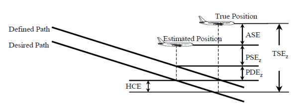
Maximum vertical total system error (TSEZ)
TSEZ should be calculated as the combination of the altimetry system error (ASE), the vertical path steering error (PSEZ), the vertical path definition error (PDEZ) and the horizontal coupling error (HCE) — see the figure below. Vertical navigation accuracy (TSEZ) is expected to be achieved for at least 99.7 % of the flight time. Assuming that these four errors are Gaussian and independent, the distribution of TSEz is also Gaussian with a standard deviation equal to the root sum square (RSS) of the standard deviations of the ASE, PSEZ, PDEZ, and HCE.
![]()
Vertical errors
(a) Altimetry system error (ASE)
Altimetry system performance is demonstrated separately from the VNAV certification through the static pressure system certification process (e.g. CS XX.1325). Altimetry systems that meet such a requirement satisfy the ASE requirements for VNAV operations. No further demonstration or compliance is necessary, and the following formula should be used to calculate the ASE (in ft) as a function of the aircraft altitude H (in ft), representing the maximum value which is expected to be achieved for at least 99.7 % of the flight time.
![]()
(b) Vertical path definition error (PDEZ)
VNAV path definition error is the error associated to the vertical path computation. It includes path definition error (PDE) and the approximation made by the VNAV equipment for the vertical path construction, if any. This is addressed through equipment approval (ETSO).
(c) Horizontal coupling error (HCE)
HCE (vertical error component of along-track positioning error) is a function of the horizontal NSE and is directly reflected in the along-track tolerance offset used in BARO-VNAV procedure design criteria. The HCE should only be taken into account in the final approach segment.
HCE is expected to be achieved for at least 99.7 % of the flight time and, in this context, may be assumed to be equal to 24 ft on a vertical path of 3 degrees°.
(d) Vertical path steering error (PSEZ)
The vertical path steering performance varies depending on how operations are conducted (manual, flight director or autopilot). The use of a flight director or autopilot may be required to support the PSEZ requirement in certain conditions. In this case, the required navigation performance (RNP) system coupling to the flight director and/or autopilot should be unambiguously displayed in the flight crew’s optimum field of view. This should also be documented in the AFM.
[Issue: CS-ACNS/2]
[Issue: CS-ACNS/4]
CS ACNS.C.PBN.560 Vertical accuracy when using SBAS/GNSS geometric altitude sources
ED Decision 2019/011/R
(See AMC1 ACNS.C.PBN.560 and GM1 ACNS.C.PBN.560)
When supporting approach operations down to LNAV/VNAV or LPV minima using SBAS/GNSS vertical position source, the accuracy of the RNP system is demonstrated to be suitable for the intended operation.
[Issue: CS-ACNS/2]
AMC1 ACNS.C.PBN.560 Vertical accuracy when using SBAS/GNSS geometric altitude sources
ED Decision 2019/011/R
The vertical total system error (TSEZ) is dependent on the navigation system error (NSE), the path definition error (PDEZ) and the flight technical error (FTEZ).
(a) Navigation system error (NSE)
The NSE should be within the accuracy requirements of ICAO Annex 10, Volume 1 to the Chicago Convention with respect to signal-in-space performance. These NSE requirements are considered to be fulfilled without any demonstration if the equipment has been granted an ETSO authorisation against ETSO-C145c, operational Class 3 or ETSO-C146c, operational Class 3 or 4.
(b) Flight technical error (FTEZ)
FTEZ is considered to be equivalent to the ILS approach if the angular deviations are displayed to the flight crew on the existing or comparable display, and the system meets the integration criteria of paragraph 7(a) of Appendix C to Subpart C of CS-ACNS and the SBAS/GNSS receiver has been granted an ETSO authorisation against ETSO-C145c, operational Class 3 or ETSO-C146c, operational Class 3 or 4.
For flight guidance systems, the FTEZ performance is considered acceptable if it meets the criteria of paragraph 7(a) of Appendix C to Subpart C of CS-ACNS and the SBAS/GNSS receiver has been granted an ETSO authorisation against ETSO-C145c, operational Class 3 or ETSO-C146c, operational Class 3 or 4.
(c) Path definition error (PDEZ)
For approaches to LPV minima, there are no performance or demonstration requirements for PDEZ. PDEZ is considered negligible based on the requirements for the FAS data block generation process.
For approaches to LNAV/VNAV minima, the applicant may assume that the PDEZ is negligible, provided that the RNP system’s internal resolution is equal to or better than the resolution provided for the path definition.
[Issue: CS-ACNS/2]
GM1 ACNS.C.PBN.560 Vertical accuracy when using SBAS/GNSS geometric altitude sources
ED Decision 2019/011/R
The lateral and vertical full-scale deflection requirements detailed in RTCA DO-229D, which is the basis for ETSO-C145c (operational Class 3) and ETSO-C146c (operational Class 3 or 4), ensure an ILS ‘lookalike’ presentation. The deflection may be fully angular with no limitation or angular but bounded at a certain value (e.g. bounded at ± 1 NM laterally and ± 150 m vertically).
[Issue: CS-ACNS/2]
ED Decision 2019/011/R
(See AMC1 ACNS.C.PBN.565)
RNP systems that provide both barometric VNAV and SBAS/GNSS VNAV perform smooth transitions from barometric VNAV to SBAS/GNSS VNAV and vice versa.
[Issue: CS-ACNS/2]
AMC 1 ACNS.C.PBN.565 Transitions
ED Decision 2019/011/R
Transitions from one source of VNAV to another should not cause discontinuities or transients that have the potential to destabilise the aircraft on final or missed approach. Aspects to consider when transitioning from one source to the other include:
(a) temperature errors, particularly if operating outside the allowable BARO-VNAV temperature range;
(b) MSL versus WGS-84 ellipsoid for path definition;
(c) curved BARO-VNAV path versus straight SBAS/GNSS path; and
(d) linear BARO-VNAV guidance versus angular SBAS/GNSS guidance.
[Issue: CS-ACNS/2]
CS ACNS.C.PBN.570 Advisory VNAV
ED Decision 2019/011/R
(See AMC1 ACNS.C.PBN.570 and GM1 ACNS.C.PBN.570)
(a) RNP systems that provide advisory VNAV comply with the criteria of this Subsection for barometric VNAV or SBAS/GNSS VNAV:
(1) Advisory VNAV provided within the FAS that is based on barometric altitude meets the intent of the temperature compensation function defined in CS ACNS.C.PBN.525.
(2) When Advisory VNAV is provided and the performance criteria of this Subsection for barometric VNAV or SBAS/GNSS VNAV cannot be met, a clear and unambiguous indication that the VNAV is advisory is provided.
(b) Advisory VNAV is based on a correct path definition:
(1) Either provided by the State’s AIP; or
(2) Through an alternative approved process.
[Issue: CS-ACNS/2]
AMC1 ACNS.C.PBN.570 Advisory VNAV
ED Decision 2019/011/R
Attachment 5 to ARINC 424 provides an acceptable method of origination of the data.
If the data does not originate from an authoritative source, the data should be validated in accordance with ED-76A, Section 2.4.1, item 6.
[Issue: CS-ACNS/2]
GM1 ACNS.C.PBN.570 Advisory VNAV
ED Decision 2019/011/R
With reference to (a)(2), the indication should be plain and easy to interpret to avoid confusion. The use of typographic characters (e.g. ‘+’ or ‘/’) as the only means to distinguish whether the vertical guidance is advisory or is referenced to a published procedure is not considered adequate.
The use of the function should be documented in AFM, pilot operating handbook (POH) or similar documents and supplements to these documents and should contain a statement to inform the flight crew that, when advisory VNAV is provided, the primary barometric altimeter should be used as the primary reference for compliance with all altitude restrictions that are associated with the instrument approach procedure, including compliance with step-down fixes.
[Issue: CS-ACNS/2]
CS ACNS.C.PBN.575 RNP system design — integrity in final approach
ED Decision 2019/011/R
(See AMC1 ACNS.C.PBN.575)
The integrity of the vertical guidance provided by the aircraft’s RNP system supports the intended operations.
[Issue: CS-ACNS/2]
AMC1 ACNS.C.PBN.575 RNP system design — integrity in final approach
ED Decision 2019/011/R
Guidance on the integrity (provisioning of erroneous output or display of data) by the RNP system related to vertical position or guidance is provided in Appendix A to Subpart C.
[Issue: CS-ACNS/2]
CS ACNS.C.PBN.580 RNP system design — continuity
ED Decision 2019/011/R
(See AMC1 ACNS.C.PBN.580)
The continuity of vertical guidance provided by the RNP system supports the intended operation.
[Issue: CS-ACNS/2]
AMC1 ACNS.C.PBN.580 RNP system design — continuity
ED Decision 2019/011/R
Guidance on the continuity (loss of the function) of the RNP system to provide vertical position or guidance is provided in Appendix A to Subpart C.
[Issue: CS-ACNS/2]
CS ACNS.C.PBN.601 Applicability
ED Decision 2019/011/R
Subsection 6 provides the supplementary functional and performance criteria that are applicable to obtain certification for RNP AR APCH. Criteria for RNP AR departures (RNP AR DP) are provided consistently with the draft ICAO Navigation Specification for RNP AR departures.
The criteria of Subsection 6 only apply to operations on RNP AR procedures designed in accordance with the requirements of ICAO Doc 9905 ‘Required Navigation Performance Authorization Required (RNP AR) Procedure Design Manual.
[Issue: CS-ACNS/2]
AMC1 ACNS.C.PBN.601 Applicability
ED Decision 2019/011/R
Compliance with the criteria of CS-ACNS for RNP AR operations ensure that the probability of the aircraft exiting the lateral or vertical extent of the obstacle clearance volume of the procedure (i.e. 2 x RNP and – 75 ft.) does not exceed 10-7 per procedure; in the case of RNP AR APCH, this includes the missed approach.
Applicants who deviate from the criteria in Subsection 6 should demonstrate that they meet the aforementioned objective.
[Issue: CS-ACNS/2]
GM1 ACNS.C.PBN.601 Applicability
ED Decision 2019/011/R
Compliance demonstration of aircraft eligibility for RNP AR approval is often a long and very demanding process. It requires full and unrestricted access to the aircraft’s safety (i.e. the data used to support compliance with CS XX.1309), aerodynamics and performance data. Furthermore, the applicant should have, as a minimum, access to a representative simulator for prolonged periods of time. Occasionally, access to the aircraft for flight testing will be required.
More stringent criteria may apply to aircraft that operate with special or proprietary procedures which are not designed to conform to ICAO Doc 9905.
Applicants who intend to apply for RNP AR approval are encouraged to contact EASA at the earliest opportunity to discuss the technical details of the compliance demonstration.
[Issue: CS-ACNS/2]
SUPPLEMENTARY SYSTEM QUALIFICATION
CS ACNS.C.PBN.605 System performance demonstration
ED Decision 2019/011/R
(See AMC1 ACNS.C.PBN.605 and GM1 ACNS.C.PBN.605)
The performance (including the RF function) of the aircraft’s system is demonstrated under a variety of operational, meteorological, and failure conditions, commensurate with the intended operation.
Criteria for assessing RNP significant failures under design limit performance conditions are the following:
(a) the lateral excursions observed as a result of probable failures are contained within a 1 × RNP corridor;
(b) the lateral excursions observed as a result of one-engine-inoperative (OEI) are contained within a 1 × RNP corridor;
(c) the lateral excursions observed as a result of remote failures are contained within a 2 × RNP corridor; and
(d) a demonstration is made that the aircraft remains manoeuvrable and a safe extraction can be flown for all extremely remote failures.
For criteria (a), (b), and (c) above, the vertical excursion does not exceed 75 feet below the desired path.
[Issue: CS-ACNS/2]
AMC1 ACNS.C.PBN.605 System performance demonstration
ED Decision 2019/011/R
The applicant should demonstrate the aircraft capability in terms of performance under design limit operational conditions (e.g. tailwinds and crosswinds, centre-of-gravity (CG) limits, temperature limits), and on representative procedures that include RF legs of varying radii. The applicant should also assess the effects of configuration changes (e.g. gear and flap extension and retraction).
The applicant should conduct a safety impact assessment based on the aircraft’s system safety assessments (SSAs) and identify any failure conditions that could potentially impact on performance. The functional hazard assessment (FHA) and SSA of all the aircraft’s systems that support RNP AR operations (RNAV systems, flight controls systems, flight guidance systems, displays, etc.) should, therefore, be revisited to identify these failures. System failures should include latent failures (‘integrity’) and detected failures (‘continuity’). For the detected failures, the monitor limit of the alert, the time to alert, the flight crew reaction time, and the aircraft response should all be taken into account and verified to ensure that the aircraft does not exit the obstacle clearance volume.
The intent of this requirement is to ensure robustness of the aircraft and its systems to failure conditions. Consequently, performing a safe extraction contingency procedure, i.e. initiating a missed approach, is not an acceptable means of demonstrating compliance against the criteria of CS ACNS.C.PBN.605(a), (b), and (c). These demonstrations may rely on crew action to intervene and place the aircraft back on the target track even if, in an operational environment, the crew is expected to initiate a missed approach procedure when the lateral or vertical criteria are exceeded. For compliance demonstration purposes, however, executing a safe extraction is not considered appropriate for demonstration of compliance with these criteria.
(a) With reference to CS ACNS.C.PBN.605(a), any failure that is classified as ‘probable’ and supports the RNP AR operation should be assessed. Those failures that would require the flight crew to act or intervene should be assessed in a representative environment and design limit operational conditions by the applicant’s flight test pilots. The impact of the failure and the flight crew intervention should be such that the aircraft can be maintained within the 1 × RNP value and within – 75 ft altitude deviation.
(b) With reference to CS ACNS.C.PBN.605(b), the same requirements apply for the case of an engine failure. If the engine failure would require the flight crew to act or intervene, then this should be assessed in a representative environment and design limit operational conditions by the applicant’s flight test pilots. The impact of the failure and the flight crew intervention should be such that the aircraft can be maintained within the 1 × RNP value and within – 75 ft altitude deviation.
(c) With reference to CS ACNS.C.PBN.605(c), the same requirements apply, except that, for the case of failures classified as ‘remote’ but not ‘extremely remote’, the impact of the failure and the flight crew intervention should be such that the aircraft can be maintained within the 2 × RNP value and within – 75 ft altitude deviation.
(d) With reference to CS ACNS.C.PBN.605(d), the applicant should demonstrate that no ‘extremely remote’ failure limits the flight crew’s ability to:
— intervene and place the aircraft back on the target track contained within the alert threshold; or
— safely extract the aircraft through manual intervention.
Safe extraction is defined as within 2 × RNP for the applicable approach and missed approach procedure, until such time that the aircraft is stabilised and reaches a safe altitude. The RNP for the missed approach procedure is usually higher than the RNP for the continued approach. For extremely remote navigational failure conditions (e.g. all flight management computers (FMCs) failed), the flight crew must be able to navigate the aircraft free of obstacles.
For departure procedures with close-in RF legs at or just beyond the departure end of the runway, and for missed approach procedures with close-in RF legs, the retraction of the landing gear and flaps and subsequent rapid acceleration may affect the RNP system’s ability to conduct accurate turn anticipation. An inaccurate turn anticipation calculation may result in an overshoot of a close-in RF turn. When this performance characteristic is present, the applicant should consider including a limiting airspeed for the initial phase of the departure or the missed approach in the AFM. The airspeed limit should not be lower than the best-climb airspeed with one-engine-inoperative.
The severity level of the above demonstrations (failure conditions in combination with the RNP approach containment requirements), as assessed by the test pilot, must still match the probability of the applicable failure condition (ref.: CS 25.1309).
Specific evaluations should be conducted to assess path excursions upon failures and the resulting RNP levels. Results should be documented in the AFM, AFM Supplement, or any appropriate aircraft operational support document which is approved by EASA and made available to the operator. In other words: If, for example, the worst-case result of the assessments that have been conducted to demonstrate compliance for ‘remote’ failures shows that the aeroplane diverts 0.40 NM from the published track, then the applicant should limit the authorised RNP to 0.20 NM.
[Issue: CS-ACNS/2]
GM1 ACNS.C.PBN.605 System performance demonstration
ED Decision 2019/011/R
As regards applications for RNP AR approval, the involvement of flight test pilots in this exercise has been shown to be crucial. Flight crew intervention is an essential aspect of these demonstrations and on occasion it has been proven difficult for flight crews to timely recognise the failure and intervene adequately. An appropriate level of specific training for RNP AR operations may be assumed.
[Issue: CS-ACNS/2]
CS ACNS.C.PBN.610 Source of horizontal position
ED Decision 2019/011/R
(See AMC1 ACNS.C.PBN.610 and GM1 ACNS.C.PBN.610)
(a) The RNP system utilises the global navigation satellite system (GNSS) as primary source of horizontal position and is backed by an inertial position source.
(b) The aircraft's RNP system does not use VOR-updating when conducting RNP AR APCH procedures.
[Issue: CS-ACNS/2]
AMC1 ACNS.C.PBN.610 Source of horizontal position
ED Decision 2019/011/R
As a minimum, the inertial positioning source needs to comply with the criteria of Appendix B. The applicant should, however, demonstrate that circular error of the inertial system supports a safe extraction, as defined in AMC1 ACNS.C.PBN.605 in case of loss of GNSS. This may imply that the design of the inertial position source needs to exceed the performance criteria described in Appendix B.
If the RNP system does not exclude VOR-updating automatically, the applicant should identify any pilot procedures for an aircraft to comply with this requirement.
[Issue: CS-ACNS/2]
GM1 ACNS.C.PBN.610 Source of horizontal position
ED Decision 2019/011/R
Integrated global navigation satellite system/inertial navigation system (GNSS/INS) or global navigation satellite system/inertial reference unit (GNSS/IRU) position solutions reduce the rate of degradation after loss of position updating. The use of a ‘tightly coupled’ GNSS/inertial system to support RNP AR operations is recommended. For ‘tightly coupled’ GNSS/inertial systems, RTCA/DO-229D Appendix R provides additional guidance.
INS or IRU are generally not considered suitable as a sole source of horizontal position for RNP AR applications described herein. However, it is recognised that many multi-sensor navigation systems utilise INS or IRU within their navigation calculations to provide continuity when the other higher accuracy sensor(s) is (are) momentarily unavailable.
Attitude and heading reference systems (AHRSs), including an AHRS with inputs from air-data computers, are generally not considered to provide a level of performance that would be adequate to support RNP AR operations, i.e. meet the criteria of Appendix B.
[Issue: CS-ACNS/2]
SUPPLEMENTARY FUNCTIONAL CRITERIA
RNP system
CS ACNS.C.PBN.615 Autopilot/Flight director
ED Decision 2022/008/R
(a) Means are provided to couple the required navigation performance (RNP) system with the autopilot or flight director.
(b) The RNP system, the flight director system and the autopilot must be capable of commanding a bank angle of up to 30 degrees above 121 m (400 ft) AGL and up to 8 degrees below 121 m (400 ft) AGL.
[Issue: CS-ACNS/2]
[Issue: CS-ACNS/4]
ED Decision 2019/011/R
(See GM1 ACNS.C.PBN.620)
When the RNP cannot be maintained during a radius to fix (RF) leg, the flight guidance mode remains in lateral navigation.
[Issue: CS-ACNS/2]
ED Decision 2019/011/R
This requirement is intended to support the flight crew in extracting the aircraft from the procedure.
[Issue: CS-ACNS/2]
CS ACNS.C.PBN.625 Go-around and missed approach
ED Decision 2019/011/R
(See GM1 ACNS.C.PBN.625)
Upon initiating a go-around or missed approach, both RNP system and the autopilot or flight director remain in lateral navigation guidance mode and continue to guide the aircraft along the lateral path of the procedure until completion of the approach and missed approach procedure.
[Issue: CS-ACNS/2]
GM1 ACNS.C.PBN.625 Go-around and missed approach
ED Decision 2019/011/R
Loss of the RNP capability is considered as a condition that would require the initiation of a missed approach.
[Issue: CS-ACNS/2]
CS ACNS.C.PBN.630 Radius to fix (RF) leg transition
ED Decision 2019/011/R
(See AMC1 ACNS.C.PBN.630)
The RNP system has the capability to execute the radius to fix (RF) leg transitions and to consistently maintain tracks, as specified in Subsection 8.
[Issue: CS-ACNS/2]
AMC1 ACNS.C.PBN.630 Radius to fix (RF) leg transition
ED Decision 2019/011/R
The demonstration of the RF capability should be undertaken considering:
(a) limit wind speed;
(b) turn radius;
(c) configuration changes;
(d) failure conditions.
With reference to failure conditions (d), the unique requirements on demonstration of performance under failure conditions of CS ACNS.C.PBN.605 apply.
[Issue: CS-ACNS/2]
CS ACNS.C.PBN.635 Navigation accuracy for RNP AR operations
ED Decision 2019/011/R
(See AMC1 ACNS.C.PBN.635)
The RNP system is capable of acquiring the RNP value associated with the intended operation.
[Issue: CS-ACNS/2]
AMC1 ACNS.C.PBN.635 Navigation accuracy for RNP AR operations
ED Decision 2019/011/R
If the RNP system offers multiple RNP values associated with lines of minima on an RNP AR approach procedure, the system should allow the flight crew to select the RNP values associated with the appropriate line of minima for use on the final approach segment. The system should then acquire the associated RNP value(s) for the procedure from the navigation database.
[Issue: CS-ACNS/2]
CS ACNS.C.PBN.640 RNP AR departures – Functional Requirements
ED Decision 2019/011/R
(See AMC1 ACNS.C.PBN.640 and GM1 ACNS.C.PBN.640)
The RNP system provides the following capabilities to support RNP AR departure procedures:
(a) The RNP system allows loading and execution of a flight plan where the initial fix of the RNP AR DP defined path is placed at or just beyond the approach end of the take-off runway.
(b) The RNP system provides lateral path guidance not later than when reaching 50 feet above the departure runway.
(c) The RNP system is capable of executing an RF leg where the first fix defining the RF leg begins at the departure end of the runway.
(d) The RNP system provides a means for the flight crew to confirm availability of GNSS for aircraft positioning immediately prior to take-off.
(e) The INS position is automatically updated upon pressing the take-off/go-around (TOGA) button or provide the ability to manually initiate a position update during ground operations immediately prior to take-off.
[Issue: CS-ACNS/2]
AMC1 ACNS.C.PBN.640 RNP AR departures
ED Decision 2019/011/R
With reference to (c), when the RNP AR DP requires a close-in turn at or just beyond the DER, retraction of the landing gear and flaps during the take-off sequence and subsequent rapid acceleration to en-route climb airspeed may compromise the RNP system’s ability to conduct accurate turn anticipation for the close-in turns, possibly resulting in the aircraft’s inability to comply with the defined turn (i.e. overshoot a close-in RF turn). Limiting the airspeed for the initial phase of the departure can help ensure the RNP system’s turn anticipation calculations are accurate.
With reference to (e), if the aircraft requires the flight crew to conduct a manual INS position update immediately prior to take-off, the applicant should provide procedures requiring the air crew to conduct the position update within 300 meter (1 000 ft) of the start point of the aircraft’s take-off roll.
[Issue: CS-ACNS/2]
GM1 ACNS.C.PBN.640 RNP AR departures
ED Decision 2019/011/R
With reference to (a), locating an initial fix of an RNP AR DP at or just beyond the approach end of the take-off runway is one acceptable means to facilitate executing an RF leg at the departure end of the runway (DER). The straight segment from the initial fix leading to the fix defining the beginning of the RF leg at the DER helps ensure the aircraft’s path is tangent to the RF leg in order to capture of the RF leg guidance.
[Issue: CS-ACNS/2]
CS ACNS.C.PBN.645 RNP AR departures – Take off performance Data
ED Decision 2019/011/R
In support of RNP AR departures, the applicant provides aircraft take off performance data, including performance on non-standard climb gradients, to the operator in a form acceptable to EASA.
[Issue: CS-ACNS/2]
Display of navigation data
CS ACNS.C.PBN.650 Display of aircraft track
ED Decision 2019/011/R
The RNP system displays the desired and current aircraft track on an electronic map display in the flight crew’s optimum field of view.
[Issue: CS-ACNS/2]
CS ACNS.C.PBN.655 Lateral deviation display
ED Decision 2019/011/R
(See AMC1 ACNS.C.PBN.655)
The full-scale deflection of the non-numeric lateral deviation display supports the intended operation.
[Issue: CS-ACNS/2]
AMC1 ACNS.C.PBN.655 Lateral deviation display
ED Decision 2019/011/R
The full-scale deflection of the non-numeric lateral deviation display should not be greater than two (2) times the applicable RNP.
[Issue: CS-ACNS/2]
Navigation database
CS ACNS.C.PBN.660 Use of a navigation database
ED Decision 2019/011/R
(See AMC1 ACNS.C.PBN.660)
The RNP system uses an on-board navigation database which provides sufficient data resolution to ensure that the RNP system achieves the required accuracy to support RNP AR operations.
[Issue: CS-ACNS/2]
AMC1 ACNS.C.PBN.660 Use of a navigation database
ED Decision 2019/011/R
Waypoint definition error should be less than or equal to 60 feet, including both the data storage resolution and the RNP system computational resolution used internally for the construction of flight plan waypoints.
The navigation database should contain vertical angles (glide path angles) stored to a resolution of hundredths of a degree, with equivalent computational resolution.
[Issue: CS-ACNS/2]
Vertical performance
CS ACNS.C.PBN.670 Vertical accuracy
ED Decision 2019/011/R
(See AMC1 ACNS.C.PBN.670 and AMC2 ACNS.C.PBN.670)
The vertical position accuracy supports the intended RNP AR operations.
[Issue: CS-ACNS/2]
AMC1 ACNS.C.PBN.670 Vertical accuracy
ED Decision 2019/011/R
When the vertical position is provided by BARO-VNAV and the aircraft performs stabilised constant descent path, the RNP system should ensure that 99.7 % of the system error in the vertical position is equal to or less than the vertical error budget (VEB) attributed to the aircraft, as defined by (in feet):
![]()
Where:
ANPE = actual navigation performance error which can be computed as follows:
![]()
WPR = waypoint precision error which can be computed as follows:
![]()
FTE = flight technical error which can be assumed to be 75 feet with autopilot or flight director coupled.
ASE = altimetry system error which can be computed as follows:
![]()
Using:
— — ‘θ’ as the vertical navigation (VNAV) path angle;
— — ‘h’ as the height in feet of the local altimetry reporting station; and
— — ‘Δh’ as the height in feet of the aircraft above the reporting station.
Note: VEBaircraft contains the elements out of the minimum obstacle clearance (MOC) equation in Appendix 1 to ICAO Document 9905 ‘Required Navigation Performance Authorization Required Procedure Design Manual’, which are attributed to the aircraft. The applicant should not apply the other elements of the MOC equation, i.e. body geometry (bg) error or international standard atmosphere temperature deviation (isad), in support of demonstration of vertical accuracy.
[Issue: CS-ACNS/2]
AMC2 ACNS.C.PBN.670 Vertical accuracy
ED Decision 2019/011/R
Where SBAS/GNSS geometric altitude is used, the installation of equipment that supports a 50-m vertical alert limit (VAL) satisfies the requirement for operations down to RNP 0.3 and the installation of equipment that supports a 35-m vertical alert limit (VAL) satisfies the requirement for operations down to RNP 0.1.
[Issue: CS-ACNS/2]
SUPPLEMENTARY PERFORMANCE CRITERIA
CS ACNS.C.PBN.675 RNP system design – RNP AR integrity
ED Decision 2022/008/R
(See AMC1 ACNS.C.PBN.675 and GM1 ACNS.C.PBN.675)
The integrity of the guidance provided by the aircraft required navigation performance (RNP) system supports the intended RNP AR operations.
[Issue: CS-ACNS/2]
[Issue: CS-ACNS/4]
AMC1 ACNS.C.PBN.675 RNP system design — RNP AR integrity
ED Decision 2019/011/R
Guidance on the integrity (provisioning of erroneous output or display of data) of the RNP system related to RNP AR operations is provided in Appendix A to Subpart C.
[Issue: CS-ACNS/2]
GM1 ACNS.C.PBN.675 RNP system design – RNP AR integrity
ED Decision 2022/008/R
The criterion of CS ACNS.C.PBN.675 applies to the integrity of the design of the system(s) that provide(s) guidance on lateral navigation (LNAV) and vertical navigation (VNAV), e.g. the design assurance level (DAL). It does not apply to the integrity of the VNAV performance.
[Issue: CS-ACNS/4]
CS ACNS.C.PBN.680 RNP system design – RNP AR continuity
ED Decision 2022/008/R
(See AMC1 ACNS.C.PBN.680 and GM1 ACNS.C.PBN.680)
The continuity of the guidance provided by the required navigation performance (RNP) system supports the intended RNP AR operations.
[Issue: CS-ACNS/2]
[Issue: CS-ACNS/4]
AMC1 ACNS.C.PBN.680 RNP system design — RNP AR continuity
ED Decision 2019/011/R
Guidance on the continuity (loss of the function) of the RNP system to provide lateral and vertical position or guidance is provided in Appendix A to Subpart C.
[Issue: CS-ACNS/2]
GM1 ACNS.C.PBN.680 RNP system design – RNP AR continuity
ED Decision 2022/008/R
The criterion of CS ACNS.C.PBN.680 applies to the continuity of the design of the required navigation performance (RNP) system(s) that provide(s) guidance on lateral navigation (LNAV) and vertical navigation (VNAV). It does not imply recognition of, or a step towards, vertical RNP or similar concepts.
[Issue: CS-ACNS/4]
CS ACNS.C.PBN.701 Applicability
ED Decision 2019/011/R
Subsection 7 provides the supplementary functional and performance criteria that are applicable to obtain certification for applications for advanced-RNP (A-RNP).
[Issue: CS-ACNS/2]
SUPPLEMENTARY FUNCTIONAL CRITERIA
RNP system
CS ACNS.C.PBN.705 Radius to Fix
ED Decision 2019/011/R
The RNP system has the capability to execute radius to Fix (RF) legs (as specified in Subsection 8).
[Issue: CS-ACNS/2]
CS ACNS.C.PBN.710 Parallel offset
ED Decision 2019/011/R
The RNP system has the capability to implement parallel offset (as specified in Subsection 10).
[Issue: CS-ACNS/2]
CS ACNS.C.PBN.715 RNP scalability
ED Decision 2019/011/R
The RNP system has the capability to operate with RNP values (ranging from 0.3 to 1.0 NM in tenth(s) of NM). The RNP value is either retrievable automatically from the on-board navigation database or manually adjustable by the flight crew.
[Issue: CS-ACNS/2]
AMC1 ACNS.C.PBN.715 RNP scalability
ED Decision 2019/011/R
Installation of equipment with an ETSO authorisation against ETSO-C115d satisfies the requirement.
[References: ED-75D § 3.7.2.1.3.1, ED-75D § 3.2.6, ED-75D § 3.2.6.2]
[Issue: CS-ACNS/2]
Display of navigation data
CS ACNS.C.PBN.725 Display of aircraft track
ED Decision 2019/011/R
The RNP system displays the current aircraft track (or track angle error) in the flight crew’s optimum field of view.
[Issue: CS-ACNS/2]
CS ACNS.C.PBN.801 Applicability
ED Decision 2019/011/R
Subsection 8 provides the supplementary functional and performance criteria that are applicable to obtain certification for the capability to execute radius to fix (RF) path terminators.
The RF functionality is mandatory to obtain A-RNP and RNP AR certification, and can be optionally associated with RNP 1, RNP 0.3 and RNP APCH.
[Issue: CS-ACNS/2]
SUPPLEMENTARY FUNCTIONAL CRITERIA
RNP system
CS ACNS.C.PBN.805 RF functional requirements
ED Decision 2019/011/R
(See AMC1 ACNS.C.PBN.805 and GM1 ACNS.C.PBN.805)
The RNP system coupled with an autopilot or a flight director is capable of:
(a) executing the radius to fix (RF) legs; and
(b) commanding and achieving a minimum bank angle of up to 30 degrees above 400 feet above ground level (AGL) and up to 8 degrees below 400 feet AGL.
[Issue: CS-ACNS/2]
AMC1 ACNS.C.PBN.805 RF functional requirements
ED Decision 2019/011/R
The applicant should perform an evaluation of the navigation system on a representative set of procedure designs under all foreseen operating conditions. The evaluation should address maximum assumed crosswind and maximum altitude with the aircraft operating in the range of expected airspeeds for the manoeuvre and operating gross weights and CG conditions (i.e. forward/aft). Procedure design constraints should include sequencing multiple, consecutive RF leg segments of varying turn radii, including consecutive RF leg segments reversing the direction of turn (i.e. reversing from a left-hand RF turn to a right-hand RF turn).
When evaluating flight technical error on RF legs, the effect of rolling into and out of the turn should be considered.
Within the demonstration, the applicant should be seeking to confirm that the FTE is commensurate with the RNP navigation accuracy.
Where applicable, the ability of the aircraft to maintain an appropriate FTE after a full or partial failure of the autopilot and/or flight director should also be demonstrated.
Any limitations identified during the compliance demonstration should be documented. Flight crew procedures should be assessed, including identification of any limitations which surround the use of pilot selectable or automatic bank angle limiting functions and confirmation of those related to go-around or missed approach from an RF leg segment.
Test procedures for aircraft capability to perform RF legs in approach and departure should make use of the RF leg demonstration templates described in Appendix D to Subpart C.
[Issue: CS-ACNS/2]
GM1 ACNS.C.PBN.805 RF functional requirements
ED Decision 2019/011/R
The test procedure is designed to provide 5 degrees of manoeuvrability margin to enable the aircraft to get back on the desired track after a slight overshoot at the start of the turn.
Industry standards for RF defined paths can be found in EUROCAE ED-75D (RTCA DO-236C Change 1).
ED Decision 2019/011/R
If the RNP cannot be achieved during a radius to fix (RF) leg, the flight guidance mode remains in lateral navigation.
[Issue: CS-ACNS/2]
CS ACNS.C.PBN.815 Autopilot/Flight director
ED Decision 2019/011/R
(See AMC1 ACNS.C.PBN.815)
The use of autopilot or flight director is required to execute radius to fix (RF) leg transitions, except for CS‑23 Level 1, 2, and 3 aircraft, for which no type rating is required, and that are performing RNP 1 and RNP APCH operations with an RNP value of not less than 1, and at speeds of 200 knots or less, provided that, in addition to the requirement stated in CS ACNS.C.PBN.820, the aircraft is equipped with an appropriately scaled course deviation indicator (CDI).
[Issue: CS-ACNS/2]
AMC1 ACNS.C.PBN.815 Autopilot/Flight director
ED Decision 2019/011/R
The applicant should perform an evaluation to demonstrate that the aircraft can be maintained on the desired path, without excessive deviations, under all foreseen operating conditions. The demonstrations should be performed on a representative set of procedure designs.
[Issue: CS-ACNS/2]
Display of navigation data
CS ACNS.C.PBN.820 Display of computed path
ED Decision 2019/011/R
The RNP system displays the intended path on an appropriately scaled moving map display in the flight crew’s maximum field of view.
[Issue: CS-ACNS/2]
CS ACNS.C.PBN.901 Applicability
ED Decision 2019/011/R
Subsection 9 provides the supplementary functional and performance criteria that are applicable to obtain FRT certification.
The FRT functionality can optionally be associated with RNP 2, RNP 4, and advanced RNP (A-RNP) specifications.
[Issue: CS-ACNS/2]
SUPPLEMENTARY FUNCTIONAL CRITERIA
RNP system
CS ACNS.C.PBN.905 Fixed radius transition (FRT) requirements
ED Decision 2019/011/R
(See AMC1 ACNS.C.PBN.905and GM1 ACNS.C.PBN.905)
The RNP system is capable of defining, executing and maintaining a track consistent with an FRT between flight path segments, using a 0.1-NM resolution for the radius value.
[Issue: CS-ACNS/2]
AMC1 ACNS.C.PBN.905 Fixed radius transition (FRT) requirements
ED Decision 2019/011/R
The installation of equipment with an ETSO authorisation against ETSO-C115d satisfies the requirement.
[Reference ED-75D § 3.2.5.4.2]
[Issue: CS-ACNS/2]
GM1 ACNS.C.PBN.905 Fixed radius transition (FRT) requirements
ED Decision 2019/011/R
FRT requirements are defined in Aeronautical Radio, Inc. (ARINC) 424, and their application is described in more detail in EUROCAE documents ED-75D (RTCA DO-236C Change 1).
[Issue: CS-ACNS/2]
Display of navigation data
CS ACNS.C.PBN.910 Display of the computed path
ED Decision 2019/011/R
The RNP system displays the computed curved path of the FRT on an appropriately scaled moving map display in the flight crew’s maximum field of view.
[Issue: CS-ACNS/2]
CS ACNS.C.PBN.1001 Applicability
ED Decision 2019/011/R
Subsection 10 provides supplementary functional and performance criteria that are applicable to obtain certification for parallel offset which enables the aircraft to fly a path parallel to, but offset left or right from, the original active route (parent route). Parallel offset is applicable only for en-route segments and is not foreseen to be applied on standard instrument departures (SIDs), standard instrument arrivals (STARs) or approach procedures.
The parallel offset functionality is mandatory to obtain RNP 4 and A-RNP certification, and can be optionally associated with RNP 2 specifications.
[Issue: CS-ACNS/2]
SUPPLEMENTARY FUNCTIONAL CRITERIA
RNP system
CS ACNS.C.PBN.1005 Parallel offset capabilities
ED Decision 2019/011/R
(See AMC1 ACNS.C.PBN.1005)
(a) The RNP system has the capability to:
(1) define a offset path from the parent track and transit to and from the offset track maintaining an intercept angle of 30 degrees;
(2) manually initiate and cease the parallel offset path;
(3) automatically cancel the offset path:
(i) following an amendment of the active flight plan by executing a ‘direct-to’;
(ii) approaching the first fix of an instrument approach procedure (initial approach fix (IAF), initial fix (IF), or final approach fix (FAF));
(iii) approaching the commencement of a segment which is not compatible with the offset.
An advance notice of the automatic cancellation is given to the flight crew and the RNP system allows sufficient time for the aircraft to return to the parent track before the commencement of the incompatible leg or the first fix of the instrument approach procedure.
(b) When executing a parallel offset, the RNP system applies to the offset route all performance requirements and constraints of the original route, as defined in the active flight plan.
[Issue: CS-ACNS/2]
AMC1 ACNS.C.PBN.1005 Parallel offset capabilities
ED Decision 2019/011/R
The installation of equipment with an ETSO authorisation against ETSO-C115d, Class A, satisfies the requirement.
For RNP systems that have not been granted an ETSO authorisation against ETSO-C115d, Class A, the requirements of ED-75D (RTCA DO-236C Change 1) Section 3.7.2.2.4 ‘Parallel Offsets’ apply, with the following additions:
(a) The RNP system should have the capability to define the offset path from the parent track using an increment of at least 1 NM, left or right and with a total offset of at least 20 NM. Where the RNP system supports the definition of a single, pre-planned parallel offset using specific start and end fixes, the RNP system should:
(1) provide automatic initiation and cessation of the offset at the start and end waypoint;
(2) begin transition to the offset path at the start waypoint on the original path to join the intercept path;
(3) begin the return to the original path so that the return transition ends at the end waypoint on the original path.
With reference to CS ACNS.C.PBN.1005(a) (3)(iii), cases which are not compatible with an offset are considered to be:
(i) arrival at a fix where a course change exceeds 120 degrees;
(ii) a route segment that ends at a hold fix.
(b) When executing a parallel offset, the RNP system computes the offset reference points using the same resolution that the parent route reference points have. Where FRTs are applied, the offset track should be flown with the same turn radius as the parent track.
[Issue: CS-ACNS/2]
Display of navigation data
CS ACNS.C.PBN.1010 Indication of parallel offset status
ED Decision 2019/011/R
When in offset mode, the RNP system provides:
(a) lateral guidance parameters relative to the offset path;
(b) distance and estimated time of arrival at, or time to go to, information relative to the offset reference points;
(c) a continuous indication of the parallel offset status in the flight crew’s maximum field of view; and
(d) the cross-track deviation indication during the operation of the offset relative to the offset track.
[Issue: CS-ACNS/2]
Appendix A — Guidance on classification of Failure Conditions.
ED Decision 2019/011/R
The following table provides guidance for the classification of failure conditions, based on a generic assessment of the risks related to the execution of the flight procedure as defined in the ICAO navigation specification.
As it is not possible for EASA to consider specific aspects of a particular design or particular mitigations, EASA will consider the outcome of a functional hazard assessment (FHA) applied to the specific design. If no FHA is provided, the higher of the classification is applied.
|
Type of operation |
Continuity / Integrity |
Classification of Failure Conditions |
|
RNP 11, RNP 2, RNP 4, RNP 0.3 |
Continuity (Loss) |
Major |
|
Integrity (Erroneous) |
Major |
|
|
Advanced RNP, RNP APCH |
Continuity (Loss) |
Major2,3 |
|
Integrity (Erroneous) |
Major/Hazardous2 |
|
|
RNP AR APCH, RNP AR DP (RNP ≥ 0.3 NM) |
Continuity (Loss) |
Major/Hazardous3 |
|
Integrity (Erroneous) |
Major/Hazardous |
|
|
RNP AR APCH (RNP < 0.3 NM) |
Continuity (Loss) |
Hazardous3 |
|
Integrity (Erroneous) |
Hazardous |
1 In the RNP 1 navigation specification of the PBN Manual, the loss of function is classified as ‘minor’. Due to EASA’s decision to group all the basic requirements for lateral navigation together in Subsection 2 and not to grant specific approval for each separate navigation specification, but for the entire bundle, the failure condition has been set to ‘major’. Applicants that intend to apply for RNP 1 approval only with an intended classification of the loss of function as ‘minor’ are encouraged to consult EASA as early in the process as possible to discuss the applicable certification criteria.
2 The loss of function during the missed approach may be classified as a ‘minor’ failure condition and the integrity may be ‘major’.
3 The loss of VNAV during the final approach may be classified as a ‘minor’ failure condition, provided that lateral navigation is not affected.
Appendix B — INS/IRU standard performance and functionality
ED Decision 2019/011/R
(1) Introduction
Appendix B provides the performance and functionality criteria that an airborne INS/IRU position source should meet to support PBN operations.
(2) INS/IRU position source standard performance and functionality
(a) The equipment should support an unambiguous indication when its outputs are invalid.
(b) The navigation function of the equipment should be designed commensurate with a ‘major’ failure condition.
(c) The alignment, updating, and navigation computer functions of the system must not be invalidated by normal aircraft power transients.
(d) The equipment should provide or support the following functions and displays:
(i) valid ground alignment capability at all latitudes appropriate for the intended use of the installation;
(ii) a display of alignment status; and
(iii) the present position of the aeroplane in suitable coordinates.
(e) The circular error of the equipment should be lower than or equal to 2 nautical miles per
flight hour on a 95-per-cent basis.
Appendix C — Installation and testing guidance
ED Decision 2019/011/R
(1) Introduction
(a) Appendix C provides guidance on the installation and testing of RNP Systems. Depending on the applicable airworthiness standards, the applicant should consider the following paragraphs as indicated below:
(i) Paragraphs (2), (3), and (4) of Appendix C should always be considered.
(ii) When Subsection 3 ‘Supplementary specifications for lateral navigation in final approach’ is applicable, paragraph (5) ‘Supplementary testing for lateral navigation in final approach’ of Appendix C should be considered.
(iii) When Subsection 4 ‘Supplementary specifications for vertical navigation’ is applicable, paragraph (6) ‘Supplementary testing for vertical navigation’ of Appendix C should be considered.
(iv) When Subsection 5 ‘Supplementary specifications for vertical navigation in final approach’ is applicable, paragraph (7) ‘Supplementary testing for vertical navigation in final approach’ of Appendix C should be considered.
(v) When Subsection 7 ‘Supplementary specifications for applications for advanced RNP’ is applicable, paragraph (8) ‘Supplementary testing for applications for advanced RNP’ of Appendix C, as well as Appendix D ‘RF leg demonstration templates’, should be considered.
(2) Equipment installation
(a) The applicant should can use equipment that has been granted ETSO authorisation and, in that case, should strictly follow the equipment manufacturer installation guide.
(b) For each of the equipment installed, the applicant should verify and assess all switching and transfer functions, including electrical bus switching and failure modes under partial or complete loss of electrical power, loss of signal reception, loss of equipment interfaced with the RNP system, etc. Under such failure conditions, the applicant should:
(i) evaluate the aircraft’s system response to ensure that the switch is accomplished as expected;
(ii) verify that the switch is clearly enunciated and that any warning associated with the loss of equipment is commensurate with the requirements of CS XX.1322; and
(iii) verify that the switching itself does not induce any inaccurate guidance and that the autopilot/flight director response is appropriate.
(c) For a multi-sensor installation, under sensor failure conditions, the applicant should verify the following:
(i) that the GNSS is used as a primary source of navigation;
(ii) the transfer to an alternative navigation sensor and the appropriate switching mode and annunciation are made;
(iii) that the switch is clearly enunciated and that any warning associated with the loss of equipment is commensurate with the requirements of CS XX.1322;
(iv) that the switching itself does not induce any inaccurate guidance and that the autopilot/flight director response is appropriate; and
(v) that the remaining navigation sensors are appropriately reflected in the positioning computation of the RNP system.
(d) During simulated loss of the GNSS signal-in-space, the applicant should verify that the criteria of point (2)(c)(ii) to (2)(c)(v) are met.
(e) Initial certification of systems, including multiple (scanning) DME sensors that have not been previously certified, must be based upon a demonstration of system accuracy by recording (at intervals not greater than 15 minutes) the DME/DME sensor position and comparing it to the actual position during evaluation flights. The latest revisions of FAA AC 25-7D and FAA AC 23‑8C provide guidance on test distances from VOR and DME navigation aids. Recorded data should include sufficient signal parameters and sensor performance data to provide a clear indication of satisfactory sensor performance. The applicant should select the particular flight paths based on an analysis of critical signal characteristics, station geometry, signal coverage (including limited station availability with acceptable range), aircraft movement, etc. The system should demonstrate its ability to detect poor signal conditions, inadequate navigation capability, recovery from in-flight power failure, etc. The applicant should review and test the auto-tune logic to verify that ground stations are identified and tuned correctly.
(f) Inertial systems that satisfy the criteria of Appendix B do not need further evaluation.
(g) With regard to GNSS sensors that have been granted an ETSO authorisation against ETSO‑C146 (Class Gamma equipment), it is stipulated that the equipment will support installations with the ability to compensate for the navigation centre to antenna offset. If applicable, the applicant should confirm that the antenna to aircraft centre of navigation offset is appropriate to the installation for GNSS SBAS equipment supporting RNP APCH to LPV and LNAV/VNAV minima.
Note: The fact that the GNSS antenna is top-mounted can result in several feet of vertical difference between the antenna and the aircraft centre of navigation, significantly greater than for ILS antennas. The centre-of-navigation to wheel-crossing height should be evaluated for each installation. For most installations, a fixed vertical offset is adequate.
(h) The applicant should evaluate the accessibility of all controls pertaining to the installation of the RNP System.
(i) The applicant should evaluate the visibility of display(s) and annunciator(s) pertaining to the installation of the RNP System during day and night lighting conditions. No distracting cockpit glare or reflections may be introduced.
(3) Sensor interference testing
(a) GNSS equipment is particularly susceptible to out-of-band SATCOM emissions and in-band inter-modulation between multiple channel SATCOM installations. The applicant should not install GNSS equipment on aircraft with SATCOM transceivers, unless absence of interference with the GNSS sensor is demonstrated.
(b) Improperly used or installed GNSS re-radiators can present misleading information to GNSS equipment. Equipment manufacturers may provide mitigation against the use of erroneous data for GNSS position and navigation solutions. Possible measures include: implementing or enabling cross-checks of GNSS sensor data against independent position sources and/or other detection monitors using GNSS signal metrics or data. It is left to the applicant to determine that the method chosen by the equipment manufacturer is adequate for the aircraft integration.
(c) The applicant should demonstrate the lack of interference from VHF radios on the completed installation of navigation sensors (GNSS, DME where applicable, etc.) by tuning each VHF transmitter to the frequencies listed below and transmitting for a period of 30 seconds while observing the signal status of each satellite being received. Degradation of individually received satellite signals below a point where the satellite is no longer available will require additional isolation measures to be taken:
(i) 121.150 MHz; 121.175 MHz; 121.200 MHz; 131.250 MHz; 131.275 MHz; and 131.300 MHz (for radios with 25-kHz channel spacing); and
(ii) 121.185 MHz; 121.190 MHz; 130.285 MHz and 131.290 MHz (for radios with 8.33-kHz channel spacing);
(d) For installations on rotorcraft, the applicant should ensure that the rotor blades do not interfere with the received signals. This problem has been experienced in some rotorcraft and varies with the rotation rate.
(4) Generic testing for performance-based lateral navigation
(a) The applicant should evaluate the navigation parameters displayed on cockpit instruments (such as HSI, CDI, distance display, electronic flight instrument system, moving maps, FMSs, etc.) against the relevant criteria. In particular, the parameters displayed should be consistent across the cockpit, especially the aircraft heading or track reference (magnetic or true), the aircraft altitude (feet or metres), and the aircraft speed (knots or km/h).
(b) The applicant should verify that the RNP system continuously provides to the flight crew:
(i) an estimation of the present position, the position accuracy and integrity;
(ii) the computed desired path and the deviation from that path; in particular, the applicant should:
(1) evaluate the sensitivity of the deviation display;
(2) verify that the full-scale setting is appropriate for the intended operation; and
(3) when applicable, verify that when the full-scale setting changes, the display of the updated deviation is appropriate;
(iii) the identification of the active TO waypoint;
(iv) the distance, bearing and time to the active TO waypoint; and
(v) the aircraft ground speed.
This behaviour should be evaluated for different flight phases, altitudes, and under various normal aircraft manoeuvres (e.g. bank angles of up to 30 degrees and pitch angles associated with take-off, departures, approaches, landing, and missed approaches, as applicable).
(c) The applicant should verify that the course selector and the RNP system are properly integrated. The behaviour of the system and the display of the aircraft heading and the selected course should be appropriate and consistent when the aircraft follows the RNP system’s flight plan but also when the aircraft is manually flown.
(d) The applicant should verify the automatic and manual selection/deselection of sensor types and positioning aids, in particular:
(i) The appropriate automatic sensor selection should be verified, and, where a multi-sensor system is installed, the applicant should check that the automatic selection is consistent with GNSS being the primary source of horizontal position;
(ii) Where a multi-sensor system is installed, the applicant should verify the appropriate automatic reversion when one or several sensors fail;
(iii) The applicant should verify the appropriate automatic selection and tuning of positioning navigation aids. Where DME is installed, the automatic selection and tuning should be evaluated where multiple DME can be received from the aircraft, for different flight phases and different altitudes. For each sensor, the applicant should verify the continuous aircraft position estimations for different flight phases, altitudes, and various normal aircraft manoeuvring (e.g. bank angles of up to 30 degrees and pitch angles associated with take-off, departures, approaches, landing and missed approaches as applicable);
(iv) The applicant should check the capability to manually override the selection or deselection of a positioning sensor type and positioning navigation aids.
(e) The applicant should verify the capability to create, review, modify and activate a flight plan. In particular, the applicant should verify the capability to extract and load procedures from the navigation database into the RNP system. During the extraction, all procedures’ characteristics (sequence of waypoints, speed and/or altitude constraint, etc.) should be loaded into the flight plan.
(f) The applicant should evaluate the following aspects when the RNP system is interfaced with an autopilot and/or a flight director. If some issues are raised, the RNP system may still be installed, but either should not be connected to the autopilot or have an appropriate aircraft flight manual supplement/rotorcraft flight manual supplement (AFMS/RFMS) limitation that mitigates the issue.
(i) The applicant should evaluate the steering response while the flight director and/or autopilot are/is coupled to the RNP system during a variety of different track and mode changes while operating at the maximum and minimum operating speeds. This evaluation should include, as applicable:
(1) transition from en route through the approach to missed approach modes and then back to en route;
(2) intercept and track to and from a waypoint on a selected course.
(ii) The applicant should evaluate:
(1) the steering response during the automatic sequencing of various flight plan legs and transition; and
(2) the appropriate display of this sequencing to the flight crew.
In particular, the capability to execute fly-by, fly-over, and RNAV holding should be evaluated for different altitudes, wind conditions, aircraft speeds, and configurations.
(iii) The applicant should verify that the lateral manoeuvre anticipation supplied by the RNP system is appropriate for the aircraft type. The applicant should verify that an appropriate annunciation of impending waypoint crossing is provided.
(iv) The applicant should verify that execution of the ‘direct-to’ and ‘direct-to’ with intercept function with a resultant aircraft heading change do not overshoot and do not cause ‘S‑turns’.
(v) The applicant should evaluate that the autopilot response to the RNP system fault by simulating a representative fault consistent with the equipment architecture (e.g. pulling the circuit breaker). This test should be done under various navigation modes.
(vi) The applicant should verify that modification of the flight plan does not impact on the aircraft guidance until the flight plan and its modification is activated. This behaviour should be evaluated for various kinds of flight plan modifications (lateral revision, constraint insertion/deletion, etc.) and for different procedure types (departure procedures, en route, manually inserted segment, arrival procedures, etc.).
(g) The applicant should verify that the flight technical error (FTE) does not exceed the FTE credits. This test may not be necessary if the FTE has been previously established for the aircraft concerned. One acceptable way of assessing FTE is to monitor the measured cross-track deviation while either flying under autopilot control or flying manually using the navigation display provided.
(h) Tests should verify proper operation of caution indications and lateral navigation interface.
(i) Normal flight manoeuvres should not cause loss-of-system sensor inputs and the system dynamic response should be confirmed.
(j) The applicant should validate the navigational accuracy of multi-sensor equipment in each operating mode. In addition to overall system navigation performance, particular test requirements for navigational accuracy will vary depending on the particular sensors integrated in the multi-sensor equipment and whether sensor accuracy performance data has previously been obtained. The performance of each navigation sensor should be evaluated separately and in combination with other sensors as applicable.
(5) Supplementary testing for lateral navigation in final approach
(a) For installations where the autopilot has not been modified and the RNP system provides ILS-like deviations, the applicant should conduct several approaches:
(i) while flying raw data, flight director, and coupled to the autopilot, as applicable;
(ii) while intercepting before and after the final approach fix (FAF),
and check that the autopilot response is appropriate and that the displays are appropriate and consistent within the cockpit.
The objective of this test is not to verify approach performance but to ensure that the RNP system interfaces are compatible with the aircraft. In addition, the autopilot approach functionality should be evaluated to ensure compatibility with the ‘gain scheduling’ employed by some autopilots during approaches.
(b) For installations where the autopilot has been modified, the autopilot lateral control channel performance has not been assessed, or non-standard deviations are provided (not ILS-like), the approach performance will need to be evaluated by the applicant as per the latest revision of, AMC1 to CS 25.1329, FAA AC 23-17C or FAA AC 29-2C.
(c) For manual control to the approach flight path, the applicant should demonstrate that the appropriate flight display(s) provide(s) sufficient information to maintain the approach path and align with the runway or go-around without excessive reference to other cockpit displays.
(d) In order to ensure the system operates properly, the applicant should evaluate the lateral full-scale deflection while on approach.
(e) The applicant should evaluate how distance to go, course, bearing, etc., are displayed on all flight deck presentations during approach procedures when step-down fixes are included in the navigation database.
(6) Supplementary testing for vertical navigation
(a) The applicant should evaluate the autopilot response to the insertion of various altitude constraints into the RNP system’s flight plan:
(i) ‘AT or BELOW’ altitude constraint;
(ii) ‘AT or ABOVE’ altitude constraint;
(iii) ‘AT’ altitude constraint;
(iv) ‘WINDOW’ altitude constraint.
The autopilot response should be evaluated under various conditions (different aircraft configurations and speeds, different lateral paths, and transitions at the altitude constraint, etc.).
(7) Supplementary testing for vertical navigation in final approach
(a) For installations where the autopilot has not been modified and the RNP System provides ILS-like deviations, the applicant should conduct several approaches:
(i) while flying raw data, flight director and coupled to the autopilot, as applicable;
(ii) while intercepting before and after the final approach fix (FAF),
and check that the autopilot response is appropriate and that the displays are appropriate and consistent within the cockpit.
The objective of this test is not to verify approach performance, but to ensure that the RNP system interfaces are compatible with the aircraft. In addition, the autopilot approach functionality should be evaluated to ensure compatibility with the ‘gain scheduling’ employed by some autopilots during approaches. For example, some autopilots depend upon a radio altimeter or middle marker beacon passage inputs to enable a ‘glideslope extension’ function to reduce oscillating or aerodynamic instability when coupled to a glideslope signal during the final approach phase. As PBN approaches do not have middle marker beacons, the autopilot response needs to be evaluated when incorporating the PBN capability.
(b) For installations where the autopilot has been modified, the autopilot lateral control channel performance has not been assessed, or non-standard deviations are provided (not ILS-like), then the approach performance will need to be evaluated by the applicant as per the latest revision of AMC1 to CS 25.1329, Appendix B of CS-29, FAA AC 23-17b or equivalent means.
(c) For manual control to the approach flight path, the applicant should demonstrate that the appropriate flight display(s) provide(s) sufficient information to maintain the approach path and align with the runway or go-around without excessive reference to other cockpit displays.
(d) In order to ensure that the system operates properly, the applicant should evaluate the vertical full-scale deflection while on approach.
(e) A flight crew workload analysis when operating the RNP system in association with other piloting requirements should be conducted by the applicant during all phases of flight and found to be acceptable, including those non-normal procedures that can be evaluated in flight.
(f) Where the RNP System is capable of automatically intercepting a vertical path, the vertical fly-by and the autopilot response (if applicable) should be evaluated under different configurations and winds.
(g) If the equipment uses barometric input, the applicant should verify that the equipment properly interprets the barometer reading. Special consideration should be given to manually entering barometric corrections.
(h) The initial certification of each BARO-VNAV system to be used for IFR approach operations should be based on a system-performance demonstration by recording the BARO-VNAV equipment vertical guidance and comparing it to the actual aircraft position along a pre-established vertical flight path. This evaluation can be made by using the actual coded path and appropriate path definition.
(i) Data should be gathered using a variety of descent rates, angles, and lateral navigation source inputs available to the BARO-VNAV system.
Note: GNSS SBAS LNAV/VNAV most closely emulates BARO-VNAV performance.
(j) When a Class A TAWS is installed and LPV minima are foreseen to be used, the applicant should verify the interface between the TAWS and the RNP system by checking the excessive downward deviation from the glide path.
(k) When temperature compensation is enabled, the applicant should ensure that the display of corrected altitude(s) is consistent on all displays in the cockpit.
(l) Where the RNP system provides both Barometric VNAV and SBAS/GNSS VNAV, the applicant should ensure that transitions from one source to the other do not result in transients or jumps that would cause either a sudden change in aircraft position on the flight path or in commands that could contribute to destabilisation of the aircraft.
(8) Supplementary testing for applications for advanced RNP
(a) The applicant should evaluate the aircraft response to the insertion of a hold to a manual termination. This evaluation should be performed at different altitudes, under different wind conditions, and for different aircraft operating speeds.
(b) RF legs should be evaluated as detailed in Appendix D.
(c) The use of different navigation accuracies (RNP values) between 0.3 and 1 NM should be evaluated. The applicant should particularly evaluate the aircraft response to navigation accuracy changes and should check that:
(i) the display update following the navigation accuracy change is appropriate;
(ii) the display of the updated navigation accuracy is consistent with all displays in the cockpit; and
(iii) the steering response while the flight director and/or autopilot are/is coupled to the RNP system during the navigation accuracy change is appropriate.
Appendix D — RF leg demonstration templates
ED Decision 2019/011/R
(1) Applicants must demonstrate the aircraft’s capability to perform all types of RF legs that can be published on instrument procedures as per the procedure design criteria. Appendix D provides templates that are an acceptable method to demonstrate an aircraft’s capability to perform RF legs. Applicants may use engineering simulations and/or aircraft for the flight test demonstrations. The templates depict the various RF legs that procedure designers may use when constructing actual initial, intermediate, missed approach, or final approach segments for RNP approaches along with SIDs and STARs. Applicants may use the templates to create one or more approach procedures at the desired aerodrome for flight test demonstration purposes in visual meteorological conditions only. The intent of such demonstrations is to streamline the airworthiness approval for conducting RF legs.
(2) The demonstration procedures need to include the depicted RF leg types shown in AppD-2. To increase flight test efficiency, it is acceptable for applicants to link the individual RF legs that are depicted in the figures by using straight segments to create ‘mega procedures’ for demonstrating the aircraft’s capability. However, the reflex curve legs (‘S-turns’) and decreasing radius turns must not have a straight segment between the path terminators (see Figure 1 below for an example). The point is to demonstrate that the aircraft is capable of flying the various types of turns including turns of minimum radius.
Note: Figure 1 is only an example and is not intended as the only possible combination for creating efficient flight profiles.
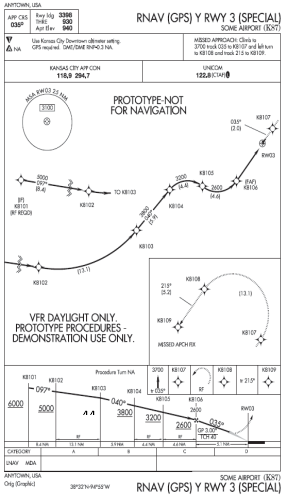
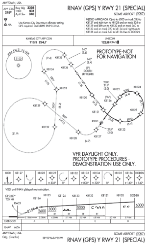

Figure 1: Example procedure profiles
(4) AppD-2 provides a basic description, illustration, and waypoint information for the RF legs.
A ‘test guide’ in AppD-3 lists a recommended testing regimen and considerations for test conduct, but the applicant can tailor the test regimen as needed.
AppD-2 — Description of test procedures
Each of the procedures is described in this section along with an image for illustration.
AppD-2.1 — Departures
(1) Design criteria for departures are currently being developed. Subsequently, two procedures were designed using known criteria in addition to criteria features that are likely to be incorporated. One of the procedures mimics a conventional design at Boston Logan International Airport that has proven difficult for some high-performance aircraft to use. Due to environmental restrictions on the ground track, the previous conventional procedure incorporates a series of short track-to-fix (TF) legs that, when viewed from a larger perspective, ‘looks’ like a series of RF legs when considering that each of the waypoints are ‘fly-by’. However, in the conventional format, some FMSs have difficulty with the short leg segments and, therefore, annunciate an inability to capture a subsequent leg. The resolution to this issue is the RF leg or a series of RF legs that ensure conformance to the desired ground path. The ‘Alpha departure’ shown in Figure 2 incorporates an RF leg shortly after take-off followed by a straight climbing segment to a series of two back-to-back RF legs with reducing radii. Waypoint information is shown in Table 1.
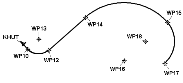
Figure 2: Alpha departure
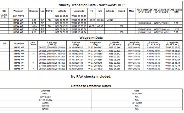
Table 1: Alpha departure waypoints
(2) The ‘Bravo departure’ shown in Figure 3 consists of an RF leg shortly after take-off followed by a brief straight segment, then two back-to-back RF legs with a turn direction reversal. The turn radii also vary as the aircraft climbs and increases performance. Waypoint information is shown in Table 2.
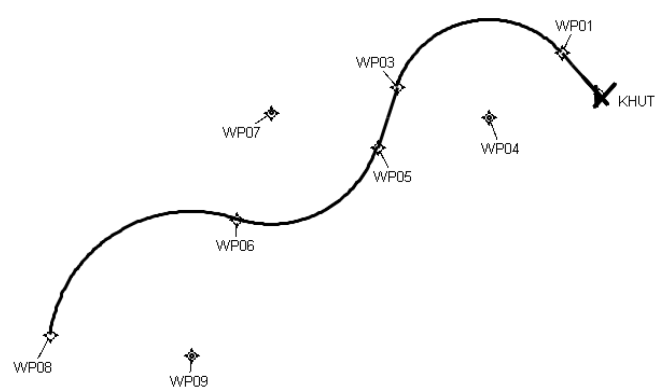
Figure 3: Bravo departure
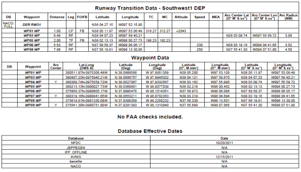
Table 2: Bravo departure waypoints
AppD-2.2 — Arrival
(1) A single arrival was designed which is similar to a previously studied design at Fargo, North Dakota, USA. As the aircraft descends and decelerates, it follows a path that consists of a series of RF legs with a reversal of the turn direction after the first turn. The second directional turn consists of two back-to-back RF legs with decreasing radii. The arrival is shown in Figure 4 and waypoint information is shown in Table 3.
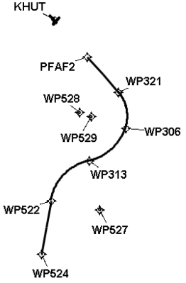
Figure 4: Arrival
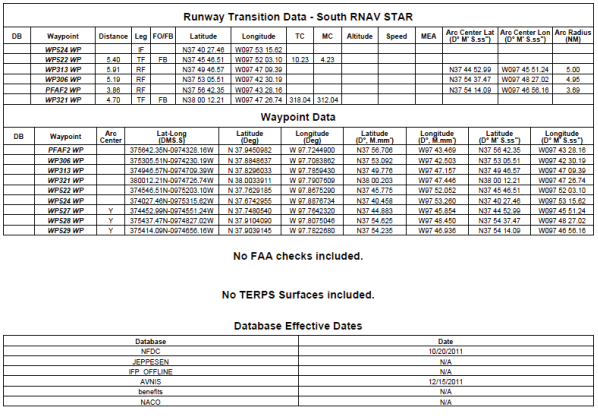
Table 3: Arrival waypoints
AppC-2.3 — Approaches
(1) Three approaches are provided to assess avionics guidance capability through a series of RF leg approach designs. These templates are acceptable for demonstrating the aircraft’s capability to perform both RNP AR and standard RNP APCH approach procedures.
(2) As shown in Figure 5, Approach 1 is a teardrop procedure that incorporates a descending RF right turn to final, rolling out at the final approach fix. Note that there is no straight segment 2 NM prior to the final approach fix which will be stressing for RNP APCH final approach guidance due to the reduced scaling transition from terminal mode to approach mode. This path requires the aircraft to descend, decelerate, and then configure for landing all during the RF leg. The missed approach also contains an RF leg en route to the missed approach hold. Waypoint information is shown in Table 4 and vertical error budget information is shown in Table 5.
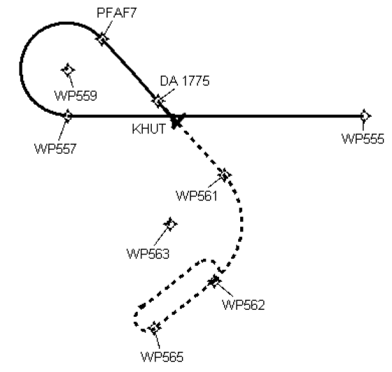
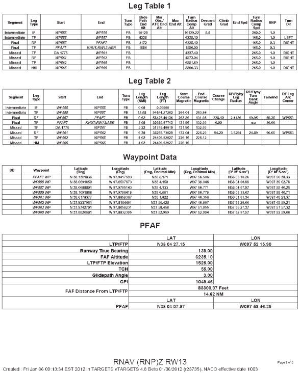
Table 4: Approach 1 waypoint information

Table 5: Approach 1 vertical error budget (VEB)
(3) Approach 2, as shown in Figure 6, is also a descending right turn to final but has a series of four RF legs with differing radii. Similar to Approach 1 in Figure 5, this path will require the aircraft to descend and decelerate during the RF leg. Waypoint information is shown in Table 6 and vertical error budget information is included in Table 7.
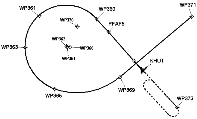
Figure 6: Approach 2
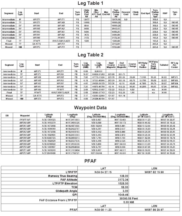

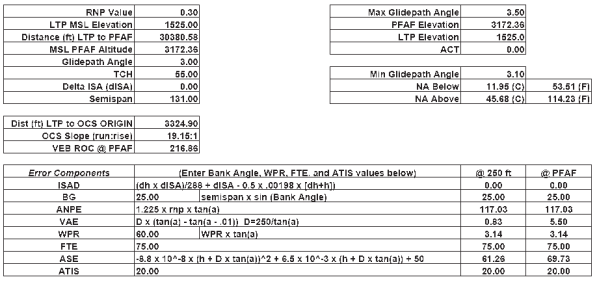
Table 7: Approach 2 vertical error budget (VEB)
(4) Approach 3 is shown in Figure 7. This procedure uses an RF leg early in the procedure followed by a brief straight segment, then two back-to-back RF legs with a turn direction reversal. The second RF leg terminates at the final approach fix. As on the other approaches, the aircraft will be required to descend, decelerate, and configure for landing during the series of RF legs. The missed approach also includes an RF leg to the missed approach hold. Waypoint information is shown in Table 8 and vertical error budget information is included in Table 9.
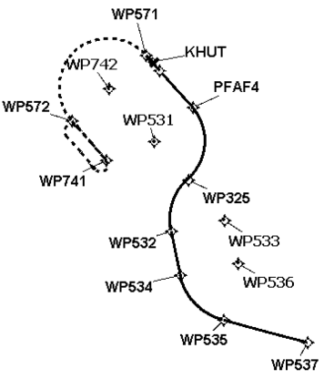
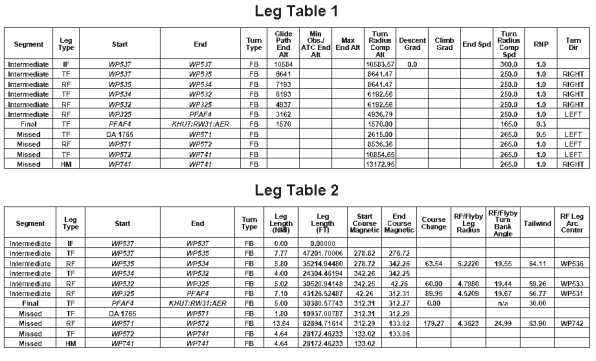
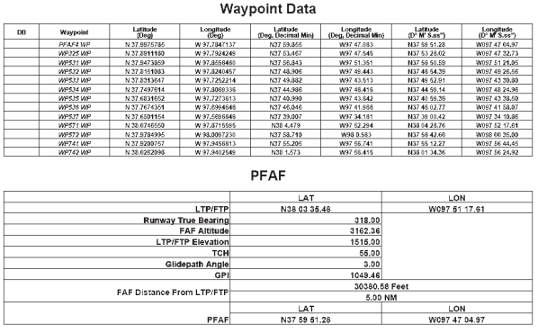
Table 8: Approach 3 waypoints
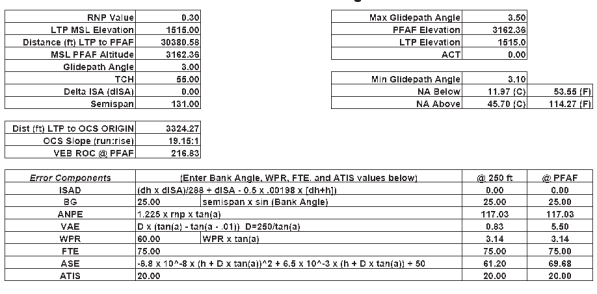
Table 9: Approach 3 vertical error budget (VEB)
(1) AppD-3 provides guidance that may be used to conduct development and/or airworthiness RF leg testing for new equipment hardware/software, or updates to existing equipment hardware/software. The guidance is designed to be used together with the templates described in AppD-2 to create .‘FOR TEST ONLY’ terminal area instrument procedures (departures, arrivals, and approaches). The intent of this regimen is to provide a set of rigorous instrument procedures that the applicant can use to demonstrate that the RF leg airworthiness approval criteria are met.
(2) The test instrument procedures are designed and located at an aerodrome with an elevation of approximately 1 500-ft MSL. The waypoint and navigation leg data is provided so that the procedures can be ‘translated’ to another location suitable to the applicant. However, the new aerodrome elevation should be within the range of 1 000–2 000-ft MSL to ensure that the designed turn radii and bank angles do not change significantly (see AppD-1). The applicant will be required to obtain a navigation database for their respective navigation system that contains the test procedures.
(3) The information in the following paragraphs describes test conditions such as generic aircraft performance parameters, desired atmospheric conditions, and considerations to assist the applicant with creating a detailed test plan. Applicants are encouraged to use these recommended guidelines. However, amendments may be made as required to accommodate unique equipment designs, test environment, testing methods, or other considerations.
AppD-3.1 — Initial set-up
(1) Configure the aircraft for individual trials using two gross weight conditions:
(a) nominal heavy weight resulting in lower accelerations to climb speed and higher speeds on approach;
(b) nominal light weight resulting in higher accelerations to climb speed and lower speeds on approach.
(2) The test should be performed in representative operational conditions in terms of speeds, flap, and gear settings, etc.
(3) Verify that a navigation database with the ‘FOR TEST ONLY’ terminal procedures is loaded in the RNP system.
(4) Verify that desired data parameters will be recorded (if data recording capability is available).
Note: In addition to the desired data parameters, the lateral path definition (desired path) and lateral path ‘cross-track error’ (distance from the path’s centre line) should be included in the recorded data parameters to monitor/review path maintenance performance.
(5) Configure the simulation, if practical, for trials using two atmospheric conditions:
(a) standard day, with standard lapse rate;
(b) 35 °C outside air temperature, with standard lapse rate.
(6) If practical, simulated wind direction should be set to a tailwind for each turn entry. Below 2 000-ft AGL, the wind velocity should be fixed at 30 kt. At 2 000-ft AGL and above, the wind velocity in knots (VKTW) should be calculated as a function of the altitude in feet (A) in accordance with the formula:
![]()
If impractical (i.e. when the simulator cannot model variable winds and various levels), select the wind direction and velocity that most effectively simulates the worst-case tailwind for the procedure.
AppD-3.2 — Airborne test conditions
(1) Record aircraft configuration:
(a) verify that the simulation is ‘conformed’ with correct avionics hardware and software;
(b) record aircraft performance parameters (gross weight, etc.);
(c) record aircraft configuration and changes to the configuration (flap, gear, and thrust setting, etc.).
(2) Select the procedure to be tested, load the procedure into the route of flight, and verify the procedure is in the active route.
(3) Ensure the correct RNP values correspond to the appropriate value for the respective route/procedure segment.
(4) Engage lateral and vertical path guidance where applicable.
(5) Engage autopilot/flight director (as soon as practical after take-off) and verify the autopilot/flight director is providing guidance to the lateral path.
(6) Fly the programmed route and observe that the lateral cross-track deviation does not exceed the FTE for the respective RNP level as follows:
|
RNP |
FTE |
|
1.0 |
0.5 NM |
|
0.3 |
0.25 NM with flight director / 0.125 NM with autopilot |
|
< 0.3 |
Agreed allowable FTE value to achieve TSE ≤ 1 × RNP value |
Table 10: FTE value versus RNP value
(7) Perform steps (1) through (6) for each appropriate aircraft gross weight configuration and for each test procedure.