
VTOL.2100 Mass and centre of gravity
n/a
(a) The applicant must determine limits for mass and centre of gravity that provide for the safe operation of the aircraft.
(b) The applicant’s design must comply with each requirement of this Subpart at critical combinations of mass and centre of gravity within the aircraft’s range of loading conditions using acceptable tolerances.
(c) The condition of the aircraft at the time of determining its empty mass and centre of gravity must be well defined and easily repeatable.
n/a
(a) Unless otherwise prescribed, an aircraft must meet the performance requirements of this Subpart in:
(1) still air and standard atmospheric conditions at sea level for all aircraft; and
(2) ambient atmospheric conditions within the operational flight envelope for:
(i) reserved.
(ii) Category Enhanced.
(b) Unless otherwise prescribed, the applicant must develop the performance data required by this Subpart for the following conditions:
(1) vertiport altitudes from sea level to the maximum altitude for which certification is being sought; and
(2) temperatures above and below standard day temperature that are within the range of operating limitations if those temperatures could have a negative effect on performance.
(c) The procedures used for determining take-off and landing area must be executable consistently by flight crew of average skill in atmospheric conditions expected to be encountered in service.
(d) Performance data determined in accordance with VTOL.2105(b) must account for losses due to atmospheric conditions, cooling needs, installation, downwash considerations, and other demands on power sources.
n/a
The applicant must determine the normal, operational and limit flight envelope for each flight configuration used in operations. The flight envelopes determination must account for the most adverse conditions for each flight configuration.
VTOL.2115 Take-off performance
n/a
(a) The applicant must determine take-off performance accounting for:
(1) operational flight envelope;
(2) reserved; and
(3) obstacle safety margins.
(b) Reserved.
(c) Reserved.
MOC VTOL.2115 Take-off performance
n/a
Testing of the take-off and landing procedures should take into consideration the “flight crew with average skills” and not be performed in particularly favourable atmospheric conditions. This implies that the performance associated with these procedures should not be determined through a single test, but rather be the result of multiple tests and take into account the normal variability of the results.
1. Introduction to take-off paths:
(a) Helicopter Category A foresees two possible take-off paths, one for Conventional Take-Off (ConvTO) and another for Elevated ConvTO (EConvTO) (Figure 1). The EConvTO differs from the ConvTO operation in that a dropdown below the surface level is allowed provided obstacle clearances (15ft of edge clearance) are maintained until reaching the take-off safety speed VTOSS (defined below). These two take-off paths are applicable to the VTOL capable aircraft with some adaptations for the VTOL flight mechanics.
(b) A third take-off path, Vertical Take-Off (VTO) (Figure 1), is also proposed with the objective of providing an adapted take-off path for VTOL urban environment operations from vertiports (see “Vertical take-off and landing procedure” in section 13):
(1) Obstacle clearance is established from the height h2, which is set at the top of the vertical climb.
(2) The protection surfaces are established at the height h2, since the minimum gradients should be determined and demonstrated after reaching VTOSS.
(3) During the vertical segment, it should be possible to perform a Rejected Take-Off (RTO) before reaching the Take-off Decision Point (TDP). Visual or synthetic cues can be used. Examples of synthetic cues include cameras and other trajectory guidance systems. The intended function of the synthetic cues should be clear, and their reliability should meet the safety objectives.
(4) After the TDP it should be possible to perform a Continued Take-off (CTO). The applicant may choose to have a pure vertical or a backup (rearward) take-off trajectory. The maximum deviations from the nominal trajectories should be determined and agreed with the Agency.
(5) The TDP can be placed at any point along the trajectory. Some applicants might elect to have a TDP lower than the top of the vertical segment, if the RTO cannot be performed safely from a given height upwards while meeting the Certified Minimum Performance (CMP) following a Critical Failure for Performance (CFP). Others may set the TDP at the bottom of the vertical segment because the RTO is not a foreseen option.
(c) The differences between the three profiles lie only at the initial portion of the take-off trajectory and acceleration to forward flight, until VTOSS and a positive rate of climb (RoC) are achieved. The trajectories on Figure 1 are depicted considering that a CFP occurs soon after the TDP. A common minimum take-off path definition after VTOSS is possible (Figure 2).
(d) The engine power settings considered are not those already used for conventional turbine engines. For VTOL capable aircraft with electric propulsion, there are at the moment no specific ratings such as the 10 minutes take-off AEO rating, the 30 sec or 2 min. rating, the 2,5 min OEI rating, etc. The power ratings will be defined at project level, as they will depend on the overall configuration (rotor-borne or wing-borne), number of engines, and also failure cases (number of acceptable engine losses). Figure 2 depicts the trajectories and the engine power settings while considering the most critical condition: a Critical Failure for Performance (CFP) during the take-off phase at TDP.


Figure 1: Possible take-off paths

Figure 2: Take-off path segments definitions, after VTOSS is achieved following a CFP at TDP
2. Approved take-off paths
(a) The take-off path extends from the take-off point to a point at which the aircraft is 305 m (1 000 ft) above the take-off elevation at the final take-off configuration.
Note A: The altitudes of 61 m (200 ft) and 305 m (1 000 ft) are proposed in the development of the take-off flight path as currently used for Category A helicopters. Different take-off heights can be considered if compatible with the departure and en-route profile.
(b) The aircraft should be accelerated to VTOSS while clearing any surface by 4.6 m (15 ft).
(c) The aircraft should reach VTOSS and should continue at speeds not less than VTOSS, until it is 61 m (200 ft) above the take-off elevation, with a minimum gradient of climb at each point. The minimum gradients, derived from CS-27 and CS-29, are 4.5 % for the first segment and 2.5 % for the second segment.
(d) For ConvTO, VTOSS should be reached at or before 10.7 m (35 ft) above the take-off elevation. In the dropdown segment, in normal and CFP, not less than 4.6 m (15 ft) clearance to the take-off elevation is allowed.
(e) For the EConvTO, the aircraft may descend below the level of the take-off surface if, in so doing and when clearing the elevated vertiport edge, in normal and CFP, every part of the aircraft clears all obstacles by at least 4.6m (15 ft). The vertical magnitude of any descent below the take-off surface should be determined and published.
(f) For the VTO, VTOSS should be reached at or before 10.7 m (35 ft) above h2. The Vertical take-off and landing procedure is described in section 13 of this MOC.
(g) The aircraft configuration (e.g. tilt wings/thrust units, flaps, gear) and power settings (contingency/take-off and maximum continuous power) may automatically change along the take-off path. Configuration changes requiring action by the crew are allowed only after the aircraft reaches VTOSS.
(h) Starting at the point at which the aircraft reaches 61 m (200 ft) above the take-off elevation (or above h2), the aircraft should be accelerated to the Final Take-off Speed (VFTO) and should then be capable of a directional trajectory change with at least 3°/s:
(1) When reaching VFTO while changing directional trajectory, the aircraft should be capable of maintaining at least level flight (no descent).
(2) If the applicant elects to show compliance to the Handling Qualities requirements using the Modified Handling Qualities Rating (MHQRM), specific manoeuvres to replicate this condition should be proposed.
(3) The effect of turn rates on the minimum climb gradients, including a standard turn rate of 3°/s, should be demonstrated and published.
(4) The corresponding maximum turn radius should be measured and published.
(5) The applicant can choose to demonstrate that the aircraft can follow curved approach and take-off climb surfaces as per ICAO Annex 14, volume 2, chapter 4 or better. The effect on the minimum climb gradients should then be demonstrated and published.
3. Take-off Decision Point (TDP)
(a) The TDP is the first point defined by a combination of speed and height from which CTO is demonstrated meeting the CMP, and is the last point in the take-off path from which an RTO is assured.
(b) The Pilot’s Intervention Time after a failure, including CFP for take-off, should be set not less than 1 second, and the Pilot’s Recognition Time not less than 0.5 second, for a Pilot’s Reaction Time after the CFP of not less than 1.5 second. The pilot input, and the decision to CTO or RTO, is expected to happen after the Reaction Time is elapsed. Depending on the aircraft characteristics, cockpit and physical information, the Pilot’s Recognition Time and/or the Pilot’s Intervention Time might be longer, and therefore need to be evaluated.
Note: The take-off performance should be determined for all associated mass, atmospheric and wind conditions (see MOC VTOL.2105) so that, in case of the occurrence of the CFP event at any time after the start of take-off, the aircraft can either return to, and stop safely on the take-off area, or continue the take-off and climb out.
Note: The Pilot’s Reaction time is the sum of the Pilot’s Recognition time plus the Pilot’s Intervention time. The Pilot’s Recognition time is the time counted from the onset of the failure until the pilot is made aware of it. The Pilot’s Intervention time is the time elapsed from the moment the pilot is made aware of the failure until an input to the flight controls is made.
4. Take-off Safety Speed (VTOSS)
(a) Only primary control inceptors should be used while attaining VTOSS and while establishing the required climb gradient.
(b) VTOSS should be reached without requiring configuration changes commanded by the crew.
(c) VTOSS should be demonstrated for each weight, most critical centre of gravity position, altitude, and temperature for which take-off data are to be determined. It should also include sufficient margin for the limiting (negative) vertical wind velocity and turbulences.
(d) Flying at VTOSS should provide a steady gradient of climb of at least 4.5 % at the power rate setting declared by the applicant for the first take-off segment.
5. Final Take-off Speed (VFTO)
(a) Any control can be used while attaining VFTO and while establishing the required climb gradient, however this should not be done before an appropriate pilot’s reaction time when considering a CFP condition.
(b) VFTO can be reached and maintained requiring configuration changes, including landing gear retraction, commanded by the flight crew.
(c) VFTO should be determined for each weight, most critical centre of gravity position, altitude, and temperature for which take-off data are to be determined.
(d) Flying at VFTO should provide a steady gradient of climb of at least 2.5 % at maximum continuous power and a manoeuvring capability of not less than 3°/s of turn rate while not descending.
6. Dimension “D”
(a) The diameter ‘D’ is the diameter of the smallest circle enclosing the VTOL capable aircraft projection on a horizontal plane, while the aircraft is in the take-off or landing configuration, with rotor(s) turning if applicable (Figure 3).
(b) The diameter D should be published in metres and feet, rounded up to the next tenth.
(c) If the VTOL capable aircraft changes its dimensions during taxi or parking (e.g. folding wings), a corresponding Dtaxi and Dparking should also be provided.
(a) The heights h1 and h2 for VTOLs are the equivalent of In Ground Effect (IGE) and Out of Ground Effect (OGE) hover for rotorcraft. Because there could be no actual beneficial “ground effect” on performance of hovering close to the ground for all VTOL designs, the conventional IGE and OGE terms have been considered to be no longer applicable. Applicants may decide to establish h1 and h2 values based on other considerations, such as handling qualities or ground clearance following failure conditions. See also Section 13 “Vertical take-off and landing procedure” in this MOC.
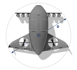
Figure 3: Centre and diameter ‘D’ of the smallest enclosing circle
8. Centre of the smallest enclosing circle
(a) The location (e.g. STA and BL) of the centre of the smallest enclosing circle used to determine D should be established and published (Figure 3).
(b) If the VTOL capable aircraft changes its dimensions during taxi or parking (e.g. folding wings) and the positions of the centre of the smallest enclosing circle varies, the corresponding locations should also be provided.
9. FATO width required
(a) ‘Final approach and take-off area’ (FATO) means a defined area over which the final phase of the approach manoeuvre to hover or land is completed and from which the take-off manoeuvre is commenced.
(b) The FATO includes the rejected take-off area.
(c) The FATO width required should be established and published in metres and feet, rounded up to the next tenth.
10. Take-off distance required (TODRV)
(a) ‘Take-off distance’ (TOD) means the projected horizontal distance from the start of a take-off procedure to:
(1) For ConvTO: the point where the aircraft reaches 10.7 m (35 ft) above the take-off surface with the minimum climb gradient of 4.5 %; or
(2) For EConvTO: after the dropdown segment, the point where the aircraft reaches 10.7 m (35 ft) above the take-off surface with the minimum climb gradient of 4.5%; or
(3) For VTO: the point where the aircraft reaches 10.7 m (35 ft) above h2 (defined in section 13 of this MOC) with the minimum climb gradient of 4.5 %.
(b) The TOD required for VTOL capable aircraft (TODRV) that provides safe obstacle clearance following a CFP being recognized at TDP should be established and published in metres and feet, rounded up to the next tenth.
11. Rejected take-off distance required (RTODRV)
(a) ‘Rejected take-off distance’ (RTOD) means the length of the FATO required by the VTOL capable aircraft to complete a rejected take-off in accordance with the Category in which it is operated, Enhanced or Basic. This value is provided in the AFM for comparison with the RTOD available for the FATO.
(b) The RTOD required for VTOL capable aircraft (RTODRV) that provides safe containment following a CFP being recognized at TDP should be established and published in metres and feet, rounded up to the next tenth.
12. TLOF size required
(a) ‘Touchdown and lift-off area’ (TLOF) means an area on which a VTOL capable aircraft may touch down or lift off.
(b) The TLOF size (length and width) required for approved procedures should be established and published in metres and feet, rounded up to the next tenth.
(c) The minimum dimensions should be the larger of:
(1) the minimum size of the surface to contain the undercarriage;
(2) the aircraft performance scatter during a landing after a Critical Failure for Performance (CFP) to a specific reference point; and
(3) the surface required to provide the minimum suitable visual cues for a landing after a CFP.
13. Vertical take-off and landing procedure
(a) The applicant may provide a procedure for a vertical take-off and landing, with a vertical segment from the ground facilitating clearance of obstacles, for example in the urban environment (Figure 4 and Figure 5).
(b) The AFM should then include the following values:
|
Parameter |
Short description |
Minimum/maximum1 |
Reference volume Type 12 |
|
h1 |
Low hover height |
- |
3 m (10 ft) |
|
h2 |
High hover height |
≥ h1 |
30.5 m (100 ft) |
|
TOwidth |
Width at h2 |
≤ 5 D |
2 D |
|
TOfront |
Front distance at h2 |
≤ 5 D |
1.5 D |
|
TOback |
Back distance at h2 |
≤ 5 D |
1.5 D |
|
FATOwidth |
Width of the FATO |
≥ 1.5 D |
1.5 D |
|
FATOfront |
Front distance on FATO |
≥ 0.75 D |
0.75 D |
|
FATOback |
Back distance on FATO |
≥ 0.75 D |
0.75 D |
|
θapp |
Slope of approach surface |
≥ 4.5% |
12.5 % |
|
θdep |
Slope of departure surface |
≥ 4.5% |
12.5 % |
Note 1: “Minimum/maximum” corresponds to the minimum or maximum values acceptable for certification.
Note 2: See (f)
(c) The published values should represent trajectories obtained with procedures demonstrated to be consistently executable without requiring exceptional piloting skill, alertness, or strength in atmospheric conditions expected to be encountered in service, as required by VTOL.2105(c).
(d) FATOfront and FATOback are referenced to the aircraft centre of the smallest enclosing circle (see section 8. of this MOC). TOfront and TOback are measured from a vertical line passing through the same point. The values published should ensure the containment of the aircraft during the procedure, for example TOback will be larger for a back-up take-off procedure and FATOfront should consider the Rejected take-off distance (RTOD).
(e) The rest of the take-off procedure (e.g. take-off decision point, drop down, climb segments) should be designed with respect to the horizontal plane at h2
(f) The applicant may develop one or multiple procedures within the maximum/minimum values provided in (b). A specific volume, called “Reference volume Type 1”, can also be proposed with standardised values that can be useful for vertiport design in an obstacle rich environment (Figure 6 and Figure 7). Demonstrating during certification that the aircraft can reliably conduct take-off and landings in this volume is offered as a possibility to the applicant to facilitate the integration in corresponding vertiports.
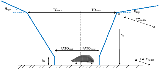
Figure 4: Generic vertical take-off and landing procedure parameters, side view

Figure 5: Generic vertical take-off and landing procedure parameters, perspective view

Figure 6: “Reference volume Type 1” vertical take-off and landing procedure parameters, side view
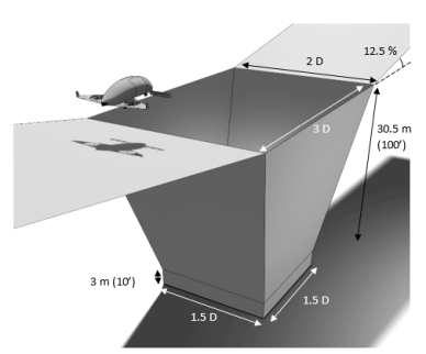
Figure 7: “Reference volume Type 1” vertical take-off and landing procedure parameters, perspective view
14. Overall width
(a) ‘Overall width’ means the widest lateral width of the VTOL capable aircraft projection on a horizontal plane, while the aircraft is in the take-off or landing configuration, with rotor(s) turning if applicable.
(b) The overall width should be established and published in metres and feet, rounded up to the next tenth.
(c) If the VTOL capable aircraft lateral width changes during taxi or parking (e.g. folding wings), a corresponding overall width during taxi or parking should also be provided.
15. Overall length
(a) ‘Overall length’ means the longest longitudinal length of the VTOL capable aircraft projection on a horizontal plane, while the aircraft is in the take-off or landing configuration, with rotor(s) turning if applicable.
(b) The overall length should be established and published in metres and feet, rounded up to the next tenth.
(c) If the VTOL capable aircraft length changes during taxi or parking (e.g. retracting tail), a corresponding overall length during taxi or parking should also be provided.
16. Undercarriage width (UCW)
(a) ‘Undercarriage width’ (UCW) means the width of the undercarriage/landing gear projection on a horizontal plane (Figure 8).
(b) The undercarriage width should be established and published in metres and feet, rounded up to the next tenth.
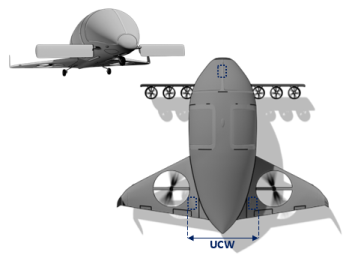
Figure 8: Undercarriage width
17. Undercarriage footprint
(a) ‘Undercarriage’ footprint means the diameter of the circle containing the landing gear contact area while the aircraft is in the take-off or landing configuration (Figure 9). The undercarriage footprint can be used for the determination of the undercarriage containment area and TLOF (touchdown and lift-off area).
(b) The undercarriage footprint should be established and published in metres and feet, rounded up to the next tenth.

Figure 9: Undercarriage footprint
18. Hover and ground (if applicable) turn diameter required
The diameters of the containment area required to perform a 360-degree turn in a normal operation hover and ground-taxi (if applicable) should be established and published in metres and feet, rounded up to the next tenth.
19. Aircraft Flight Manual Data:
The following data, defined in the previous sections of this MOC, should be included in the AFM:
(a) Approved take-off paths
(b) Take-off decision point
(c) Take-off Safety Speed (VTOSS)
(d) Final Take-off Speed (VFTO)
(e) Dimension “D”
(f) Hover heights h1 and h2 (if applicable)
(g) Centre of the smallest enclosing circle
(h) FATO width required
(i) Take-off distance required for VTOL capable aircraft (TODRV)
(j) Rejected take-off distance required for VTOL capable aircraft (RTODRV)
(k) TLOF size required
(l) Vertical take-off and landing procedure (if applicable)
(m) Overall width
(n) Overall length
(o) Undercarriage width (UCW)
(p) Undercarriage footprint
(q) Hover and ground (if applicable) turn diameter required
n/a
The design must comply with minimum climb performance out of ground effect:
(a) in the normal flight envelope.
(b) for Category Enhanced:
(1) in the operational envelope;
(2) reserved.
(c) reserved.
MOC VTOL.2120 Climb requirements
n/a
(a) For Category Enhanced, the climb gradient without ground effect, at 305 m (1 000 ft) above the take-off surface, should be at least 2.5 %, for each combination of weight and CG, altitude, and temperature for which take-off data are to be determined, and for the duration of the flight:
(1) following a critical failure for performance (CFP) and with the remaining lift/thrust engines at maximum continuous power, if approved, or at take-off power for aircraft for which certification for use of take-off power is requested; and
(2) with the landing gear retracted (if applicable) and the aircraft in cruise configuration; and
(3) at the speed selected by the applicant.
Note: The altitude of 305m (1 000 ft) is proposed as currently used for Category A helicopters. Different cruise altitudes can be considered if compatible with the departure and en-route profile.
See MOC VTOL.2115 and 2130 for specific climb requirements for take-off and balked landing.
(b) For Category Basic, the climb gradient without ground effect, at 305 m (1 000 ft) above the take-off surface, should be at least 2.5 %, for each combination of weight and CG, in nominal conditions (no failure conditions), at ISA SL and for the duration of the flight.
n/a
(a) The applicant must determine, as applicable, climb and/or descent performance:
(1) in the normal flight envelope;
(2) for Category Enhanced, in the operational envelope;
(3) reserved.
(b) The VTOL ceiling in and out of ground effect, if applicable, must be determined within the operational flight envelope.
n/a
The applicant must determine the following, at critical combinations of flight parameters within the operational limits:
(a) the area required to land and come to a stop, assuming approach paths applicable to the aircraft; and
(b) the approach and landing speeds, configurations, and procedures, which allow a flight crew of average skill to land within the published landing area consistently and without causing damage or injury, and which allow for a safe transition to the balked-landing conditions.
n/a
This MOC does not cover the approach before the landing and starts from a point at which the decision to land, from an operational point of view, has been taken.
1. Landing procedures
(a) The landing can be of two main types: a Conventional Landing (ConvL) or a Vertical Landing (VL):
(1) A ConvL path starts at a Landing Decision Point (LDP, see below) and ends at the point where the aircraft reaches a stop at the FATO on the ground (after which it may taxi). The trajectory may have the most appropriate glide path foreseen by the applicant.
(2) A VL might be required to comply with obstacle separation when landing on a Vertiport in an Urban Air Mobility (UAM) environment. The applicant may choose to have, from a point along the approach after the LDP, a pure vertical trajectory.
(b) The landing procedures should be demonstrated to be consistently executable by flight crew of average skill, as required by VTOL.2105(c).
(c) The landing distance scatter and the maximum deviations from a nominal trajectory should be determined by the applicant.
2. Landing decision point (LDP)
(a) The characteristic point along the landing flight path is the Landing Decision Point (LDP), which is defined as the last point from which a balked landing can be performed. After LDP a balked landing is not assured.
(b) If the aircraft is required to show continued safe flight and landing, then a landing should be possible following a CFP before or after the LDP.
(c) LDP should be identified with a combination of height, vertical speed and airspeed and/or ground speed.
(d) LDP should be reached at a speed equal or lower to VREF.
3. Landing reference Speed (VREF)
The landing reference speed is the speed determined at the flight Glide Path Angle (GPA) for which certification is sought and with all lift/thrust systems operative that:
(a) allows for speed variations during a landing in expected turbulence and all reasonably expected environmental conditions; and
(b) provides enough manoeuvring capability; and
(c) is the initial speed that should be used to determine the area required to land and come to a stop.
4. Landing distance required (LDRV) and touchdown and lift-off area (TLOF) required
(a) The landing distance required is the horizontal distance required to land and come to a stop from a point 15 m (50 ft) above the landing surface (Figure 1). The touchdown and lift-off area (TLOF) required is defined in MOC VTOL.2115 section (12).
(b) The landing distance required for VTOL capable aircraft (LDRV) that provides safe containment following a CFP being recognized at LDP should be established and published in metres, rounded up to the next tenth.
(a) The aircraft should be capable of a balked landing following a CFP event without requiring configuration changes commanded by the flight crew until regaining VTOSS. Reaching VTOSS could require continuing the descent, but the minimum height of 35 ft above the vertiport elevation or above h2, depending on the landing procedure, based on which the take-off distances are calculated, should be respected to ensure obstacle clearance.
(b) Once VTOSS has been regained, configuration changes are permitted, and the minimum climb gradients for the 1st and 2nd segment of the take-off path should be guaranteed (see MOC VTOL.2115).
(c) A representative time to perform a go-around from LDP back to LDP should be provided for the determination of the energy reserve.
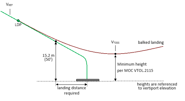
Figure 1: Landing path
6. Aircraft Flight Manual Data:
The AFM should include the following data, defined in the previous sections of this MOC:
(a) Landing procedures
(b) Landing decision point (LDP)
(c) Landing reference Speed (VREF)
(d) Landing distance required (LDRH)
(e) Balked landing procedure
n/a
(a) The aircraft must be controllable and manoeuvrable, without requiring exceptional piloting skills, alertness, or strength, within the operational flight envelope and must be controllable and manoeuvrable within the limit flight envelope:
(1) at all loading conditions for which certification is requested;
(2) during all phases of ground or flight operations;
(3) reserved;
(4) during configuration changes;
(5) in all degraded flight control system operating modes; and
(6) the applicant must demonstrate controllability in wind from zero to a wind limit appropriate for the aircraft type.
(b) Reserved.
(c) Reserved.
(d) It must be possible to make a smooth transition from one flight condition to another without danger of exceeding the limit flight envelope.
MOC VTOL.2135 Minimum Acceptable Handling Qualities Rating
n/a
1. Background and Introduction
The aircraft needs to be controllable and manoeuvrable to cope with adverse weather conditions and to avoid late detected obstacles or traffic appropriate to the type. The control and manoeuvring of the aircraft requires a certain amount of physical and/or mental workload from the crew. Satisfactory Handling Qualities (HQ) give the opportunity for the crew to better manage high workload situations, and allow them to operate safely for longer periods, and to be able to deal with aircraft system failures and contingencies. Degraded HQ lead to an increased crew attentional demand for aircraft control, hence reduced high workload capacity for other tasks and for Situational Awareness.
The following is a method of determining and evaluating, for compliance demonstration, the HQ for VTOLs in the Category Enhanced in normal and abnormal/emergency conditions. The Category Basic VTOLs may also elect to use this method; however, the Minimum Acceptable Handling Qualities Rating section 4 will need to be adapted. The focus is on the crew task of flight path/trajectory control. All the other characteristics of the flight controls such as number of inceptors, size and mechanical forces (friction, breakout etc.) are out of scope of this MOC. These other characteristics however will influence the achievable HQ, so they will be indirectly assessed.
This method is different from CS-23 and CS-27, since in those certification specifications, the HQ of an aircraft are suitably assessed on the addition of the compliance to static or dynamic stability requirements along with other requirements for controllability and average piloting skills. HQ are evaluated without any specific generally recognised method, and are mainly evaluated to measure the workload to determine the minimum crew in respect to the kind of operations. Usually the Cooper Harper Handling Qualities Rating Scale (CHR) is used to measure the Handling Qualities, while the Bedford rating scale (or NASA Task Load Index as alternative) is used to measure the workload. However, each applicant can choose the methodology to determine the HQ and/or workload.
This Modified Handling Qualities Rating Method (MHQRM) is an accepted means of compliance with VTOL.2135, and can also be used to assess compliance, fully or in part, with the following SC VTOL requirements that require a determination of HQ: VTOL.2110 Flight Envelopes, VTOL.2115 Take-off performance, VTOL.2130 Landing, VTOL.2135 Controllability, VTOL.2140 Control forces, VTOL.2145 Flying qualities, VTOL.2150 Stall characteristics and stall warning, VTOL.2160 Vibration, VTOL.2300 Flight control systems and VTOL.2305 Landing gear systems.
This method should not be considered to be the only method. Applicants may propose alternative methods or deviations based on the characteristics of their design, or on their compliance determination strategy. Unless otherwise specified in a special condition, the HQRM does not replace or override any of the systems and equipment requirements of §§ VTOL.2500, VTOL.2505 and VTOL.2510.
2. List of Acronyms
AD Atmospheric Disturbance
ADQ Adequate
AFM Aircraft Flight Manual
CHR Cooper Harper Rating Scale
CON Controllable
CONOPS Concept of Operations
EFCS Electronic Flight Control System
FC Failure Conditions
FE Flight Envelope
FEP Flight Envelope Protection
FHA Functional Hazard Assessment
FltC Flight Condition
GNSS Global Navigation Satellite System
HQ Handling Qualities
HQR Handling Qualities Rating
HQRM Handling Qualities Rating Method
IMC Instrument Meteorological Conditions
LFE Limit Flight Envelope
MHQRM Modified Handling Qualities Rating Method
MTE Mission Task Elements
NFE Normal Flight Envelope
NVIS Night Vision Imaging System
OFE Operational Flight Envelope
SAT Satisfactory
SC Special Condition
TBD To be determined
VFR Visual Flight Rules
VisC Visual cues
VTOL Vertical Take Off and Landing
3. MHQRM Process
The overall process is derived from the FAA Advisory Circular 25-7D Appendix E, which was intended mainly to define a method for evaluating Failure Conditions (FCs). In particular, the principle of determining the minimum HQR based on the probability of being in a given Flight Condition (FltC) was adopted. The “tool” to evaluate and show compliance with the minimum acceptable HQR will be derived from ADS-33E. The Mission Task Elements (MTE) manoeuvres of this military standard will be adapted to the SC VTOL based on the Concept of Operations (CONOPS) for VTOL that is being produced by industry. There will be also provisions on the competences of the test pilots (fixed wing or rotary wing background) and on the minimum number of evaluators. This tool is being developed together with industry and research centres, and will be published at a second stage.
This MHQRM starts by determining the minimum acceptable HQR for each phase of the flight and for a given FltC, defined as a combination of the Flight Envelope (FE) and the level of Atmospheric Disturbance (AD), relative to the Nominal State of the aircraft systems, or the probability of the FC being evaluated. A pre-requisite to start the MHQRM process is thus to have Functional Hazard Assessment (FHA) available and have preliminary quantitative assessments for the FCs to be analysed in the MHQRM. If this MHQRM process is intended for validating FC classification in the Aircraft FHA, early coordination with the Agency is advised.
The methodology developed in this MOC is aimed at identifying which FCs need to be considered in the handling quality assessment. One possible outcome of the HQ assessment is that the failure condition classification of a given FC needs to be increased.
To limit the risk of iterations of the FHA content and the subsequent side effects on the MHQRM, early coordination with the Agency on the safety assessment outputs (FHAs, preliminary quantitative analysis) is also advised.
The visual environment, or the quality of the Visual Cues (VisC), is not defined, and the assumption is that the VisC, in terms of external visual environment and displays/sensors feedback, are sufficient to allow the crew to perform their tasks and be able to achieve and assess Desired and Adequate HQ performance criteria. The most conservative external visual environment (Day, Night, IMC, NVIS) should be used for each phase of flight for which certification is requested. For example, if the aircraft is intended to be certified for flight in Night VFR, the climb, cruise, descent and approach phases of flight should be evaluated by using an appropriate external visual environment, while the take-off and landing phase may use a better external visual environment. The VisC will be defined in the evaluation document and should be agreed with the Agency on a case by case basis.
To apply this method it is first necessary to divide the profile of the aircraft into different phases of flight, e.g. taxi (if applicable), take-off (including rejected take-off), climb, cruise, descent, approach and landing (including landing following a failure condition and balked landing). The classification for each phase of flight is done because there could be failure conditions at aircraft level that affect HQs only in one particular phase of flight, as for example the loss of Global Navigation Satellite System (GNSS) could result in a reduced accuracy in the Translational Rate Command FCS mode in low airspeed, or a failure condition (i.e. multiple electric engine failures) could result in less precise turn coordination in cruise.
For each phase of flight, the different FltCs that have a probability of being encountered of greater than 10-9 per hour are then identified. Special care should be given also to the transition between different phases of flight and aircraft configuration changes (if any). The FltCs probability is given by combining (multiplying) the probability of the aircraft being in a specific FE, the probability of the aircraft having a FC that affects HQ (not only flight control system failures, but any other, including lift/thrust system failures) and the probability of an AD being experienced.
When there is an interrelationship between the different probabilities, the FE probability will be adjusted to take this into account. For each FltC, the minimum HQR level is assigned based on the requirements derived from SC VTOL. The applicant should then show compliance by using an approved rating tool in actual flight test, or in a simulator that has been validated and shown to be representative for the test.
4. Minimum ACCEPTABLE HQR
Table 1 describes the different Handling Qualities Rating (HQR) levels and compares them to the System Failure Classification that is contained in MOC VTOL.2510, and to the Cooper Harper Rating Scale.
Exceptional piloting skills should not be required for the achievement of any HQ performance criteria. The evaluation should assess whether Desired or Adequate criteria are met, and the associated workload in terms of physical and/or mental compensation required by the crew.
Table 1: Handling Qualities Ratings definition (Example for Cruise)
|
Handling Qualities Rating (HQR) |
Description |
MOC VTOL.2510 Failure Conditions Classifications |
Cooper Harper Rating Scale (CHR) |
|
Satisfactory (SAT) |
Handling Qualities allow achievement of desired performance criteria without exceptional piloting skills and with no or minimal pilot compensation. |
Up to Minor |
1-3 |
|
Adequate (ADQ) |
Handling Qualities allow achievement of desired performance criteria or adequate performance criteria without exceptional piloting skills and with moderate to extensive pilot compensation. |
Major |
4-6 |
|
Controllable (CON) |
Handling Qualities DO NOT allow achievement of adequate performance criteria WITHOUT exceptional piloting skills. Allows however continued safe flight and landing, without exceptional piloting skills, after a transient condition or reconfiguration to retain control, if necessary. |
Hazardous |
7-9 |
The different FE are (Table 3): Normal Flight Envelope (NFE), Operational Flight Envelope (OFE) and Limit Flight Envelope (LFE).
The AD level (Table 4) can be Light, Moderate or Severe.
The FC probabilities (Table 5) are in accordance with the aircraft level MOC VTOL.2510 quantitative probability values. Probability values for Probable up to Remote Failure Conditions have been grouped together for table readability reasons, as the minimum HQR would be the same.
It is important to highlight that NOT every combination of AD, FC and FE should be tested.
Table 2 Minimum Acceptable Handling Qualities Rating
|
FltC XFE * XFC * XAD |
Atmospheric Disturbance (AD) |
||||||||
|
Light |
Moderate |
Severe |
|||||||
|
Flight Envelope (FE) |
|||||||||
|
Failure Condition (FC) |
NFE |
OFE |
LFE |
NFE |
OFE |
LFE |
NFE |
OFE |
LFE |
|
Nominal Condition |
SAT |
SAT |
CON |
SAT |
SAT |
CON NOTE 1 |
SAT |
ADQ NOTE 1 |
CON NOTE 1 |
|
Probable up to Remote Failure Conditions: |
SAT |
ADQ |
CON |
SAT |
ADQ NOTE 1 |
CON NOTE 1 |
ADQ |
CON NOTE 1 |
CON NOTE 1 |
|
Extremely Remote Failure Conditions: |
ADQ |
ADQ |
CON |
ADQ |
CON NOTE 1 |
NOTE 2 |
CON |
NOTE 2 |
NOTE 2 |
|
NOTE 1:. This is considered to be a transient condition, and it is expected that better HQR will be achieved when the AD level is decreased. Likewise it should be demonstrated that better HQRs are achieved in the more favourable Flight Envelopes: such transition should be relatively quick and without requiring exceptional piloting skills. |
|||||||||
|
NOTE 2: This FC is shaded in red as it could possibly have a related probability lower than Extremely Improbable, and should not be considered. If the FC probability is greater than Extremely Improbable, then the minimum HQR should be CON. |
|||||||||
The probabilities in Tables 3, 4 and 5 apply when they are considered separately. When obvious interrelationships exist due to the design or the intended or expected operation of the aircraft, the way to address this within MHQRM is to modify the FE probability value. For example, for FltCs with Moderate and Severe AD levels in CRUISE and APPROACH, an atmospheric (windshear) event may require an escape operational procedure that results into entry in the LFE, resulting in a LFE probability of 100 (i.e. 1 or certain). Similarly, an aircraft flying at the boundaries of the NFE, may experience overspeed due to a gust and fall into the OFE, hence the modified FE would be 100 (i.e. 1 or certain). This probability adjustment concept would also apply to FCs where, for example, a loss of warnings or a loss of envelope protection might contribute to excursions outside the NFE or OFE, in which case the flight envelope probability should be increased appropriately. In this latter case, the change of probability will be evaluated case by case and should be agreed with the Agency.
5. Probability definitions and determination
(f) Flight Envelope (FE)
The flight envelope probabilities will depend on the aircraft architecture. The automatic envelope protection provisions (if available) and the cues to the crew will be the determining factors.
The flight crew should operate the aircraft by definition in the NFE. Excursions into the OFE and LFE are determined by AD, by transient conditions due to failures (that can have different probabilities based on the design), or by expected human errors.
These probabilities should be adjusted to account for the interrelationship between AD and FC events (section 4).
Applicants should provide probabilities based on the evidence that they have available to substantiate them, and based on their aircraft characteristics.
Visual and aural warnings, or specific aircraft characteristics at the boundaries of the envelopes (vibrations, noise) could grant credits for increasing the probability of remaining within a given FE.
Table 3: Probability of Occurrence of the Flight Envelope (FE)
|
Flight Envelope |
Notes |
Probability XFE |
|
Normal Flight Envelope (NFE) |
Generally associated with routine operational and/or prescribed conditions. At the boundaries of this envelope there could be means to raise the awareness of the crew (cautions). |
100 |
|
Operational Flight Envelope (OFE) |
The crew should be aware that the operation occurs outside the NFE. At the boundaries of the OFE, warnings and/or EFCS envelope protection means could be present. The Aircraft Flight Manual (AFM) limitations should be consistent with the boundaries of the OFE. When considering airspeed to define the envelope, the high speed boundaries of the OFE would be the current VNE. |
TBD |
|
Limit Flight Envelope (LFE) |
The crew should never operate in this envelope; a return should be made at least to the OFE. This is the maximum extent in terms of envelope that needs to be investigated from a HQ point of view but should not be included in the AFM. The boundaries of the LFE are associated with aircraft limits. |
TBD |
(g) Atmospheric Disturbance (AD)
The atmospheric disturbance level ranges from the complete absence of any disturbance up to the atmospheric disturbance level (gusts) that are considered for the structural limits of the aircraft. The AD considered could be different depending on which phase of flight is being evaluated.
Additional steady state relative winds values, for the most critical azimuth, are established to show compliance with the applicable requirements when the aircraft is operating based on ground references (e.g. Take-off, Hover, Landing).
The amplitude of the gusts to be considered for the structural design will be defined in MOC VTOL.2215 “Flight Load Conditions”. Non-symmetric gust cases should be considered when evaluating HQ. The shapes of the gusts may also be a critical factor for HQ and should be evaluated.
The steady state relative wind values are derived from the experience from CS-27, and have been identified as being 17 kt. This value is the minimum to be used for airworthiness approval; applicants may choose higher steady wind values based on market requirements.
The steady wind value should be evaluated only in the phases of flight that are close to the ground. The controllability in steady winds should be demonstrated for all FC in Light AD level (without gusts and turbulence).
The exact values of the gusts are currently not defined for each AD level. Even the related probabilities (XAD), which are modified in respect to Appendix E to AC25-7D to account for the Urban Environment, will need to be verified by recorded data which are currently not available.
Table 4: Probability of Occurrence Guidelines of Atmospheric Disturbance (AD)
|
Atmospheric Disturbance |
Notes |
Probability XAD |
|
Light: |
No appreciable turbulence and steady state winds less than 3 kt with no appreciable gusts. |
100 |
|
Moderate: |
Light to moderate turbulence. Changes in altitude and/or attitude occur. Usually causes variations in indicated airspeed. |
TBD |
|
Severe: |
Turbulence that causes large, abrupt deviations in altitude and/or attitude. Usually causes large variations in indicated airspeeds. |
TBD |
(h) Aircraft or System Failure Condition affecting HQ (FC)
The Failure Condition probabilities (XFC) relate to the probability of encountering a Failure Condition which affects HQs. This may include, but is not limited to, the FCS or lift/thrust system. The MHQRM should be linked to the Safety Assessment Process at aircraft level. Feedback should be provided into the different Safety Assessment Elements, such as the Functional Hazard Assessment (FHA), Preliminary System Safety Assessment (PSSA), Fault Tree Analysis (FTA), System Safety Assessment (SSA) or Failure Mode and Effect Analysis (FMEA), and vice versa to check if the assumptions of these Safety Assessment Elements in terms of effect (when the driving factor are HQ) are confirmed by the MHQRM evaluation.
Table 5: Probability of Occurrence Guidelines of Failure Condition affecting HQ (FC)
|
Failure Condition |
Notes |
Probability XFC |
|
Nominal Operation: |
No failures |
100 |
|
Up to Major Failure conditions: |
Failures with an effect on HQR not more severe than MAJOR. |
NOTE 3 |
|
Hazardous Failure conditions: |
Failures with a HAZARDOUS effect on HQR. |
≤10-7 NOTE 3 |
|
NOTE 3: The applicant may use any value derived from the safety assessment process, provided it meets the safety objectives. Allowable quantitative probabilities for “probable”, “remote” and “extremely remote” are defined in MOC VTOL.2510 §8 |
||
n/a
(a) Reserved.
(b) Reserved.
(c) Residual control forces must not fatigue or distract the flight crew during normal operations of the aircraft and likely abnormal or emergency operations. The trim control, if installed, must not introduce any undesirable discontinuities in control force gradients.
n/a
(a) Within its flight envelopes, the aircraft must show suitable stability and control feel, in all axes.
(b) Within its flight envelopes, no aircraft may exhibit any divergent stability characteristic, so as to require exceptional piloting skills, alertness, or strength or otherwise endanger the aircraft and its occupants.
VTOL.2150 Stall characteristics and stall warning
n/a
(a) If part of the lift is generated by a wing, the aircraft must have controllable stall characteristics in straight flight, turning flight, and accelerated turning flight with a clear and distinctive stall warning that provides sufficient margin to prevent inadvertent stalling.
(b) Reserved.
(c) Reserved.
(d) Reserved.
(e) Reserved.
n/a
(a) Each part of the aircraft must be free from excessive vibration throughout the limit flight envelope.
(b) Reserved.
(c) Reserved.
(d) Reserved.
VTOL.2165 Flight in icing conditions
n/a
(a) An applicant who requests certification for flight in icing conditions must demonstrate that the aircraft can be safely operated in the icing conditions for which certification is requested.
(b) The applicant must provide a means to detect any icing conditions for which the aircraft is not certified to operate and demonstrate the aircraft’s ability to avoid or exit those conditions.
(c) The applicant must develop an operating limitation to prohibit intentional flight, including take-off and landing, into icing conditions for which the aircraft is not certified to operate.